TWI697693B - Multibeam element-based near-eye display, system, and method - Google Patents
Multibeam element-based near-eye display, system, and method Download PDFInfo
- Publication number
- TWI697693B TWI697693B TW107145455A TW107145455A TWI697693B TW I697693 B TWI697693 B TW I697693B TW 107145455 A TW107145455 A TW 107145455A TW 107145455 A TW107145455 A TW 107145455A TW I697693 B TWI697693 B TW I697693B
- Authority
- TW
- Taiwan
- Prior art keywords
- light
- beam element
- display
- eye
- different
- Prior art date
Links
Images


Classifications
-
- G—PHYSICS
- G02—OPTICS
- G02B—OPTICAL ELEMENTS, SYSTEMS OR APPARATUS
- G02B27/00—Optical systems or apparatus not provided for by any of the groups G02B1/00 - G02B26/00, G02B30/00
- G02B27/01—Head-up displays
- G02B27/017—Head mounted
- G02B27/0172—Head mounted characterised by optical features
-
- G—PHYSICS
- G02—OPTICS
- G02B—OPTICAL ELEMENTS, SYSTEMS OR APPARATUS
- G02B27/00—Optical systems or apparatus not provided for by any of the groups G02B1/00 - G02B26/00, G02B30/00
- G02B27/10—Beam splitting or combining systems
- G02B27/106—Beam splitting or combining systems for splitting or combining a plurality of identical beams or images, e.g. image replication
-
- G—PHYSICS
- G02—OPTICS
- G02B—OPTICAL ELEMENTS, SYSTEMS OR APPARATUS
- G02B30/00—Optical systems or apparatus for producing three-dimensional [3D] effects, e.g. stereoscopic images
- G02B30/20—Optical systems or apparatus for producing three-dimensional [3D] effects, e.g. stereoscopic images by providing first and second parallax images to an observer's left and right eyes
- G02B30/26—Optical systems or apparatus for producing three-dimensional [3D] effects, e.g. stereoscopic images by providing first and second parallax images to an observer's left and right eyes of the autostereoscopic type
- G02B30/33—Optical systems or apparatus for producing three-dimensional [3D] effects, e.g. stereoscopic images by providing first and second parallax images to an observer's left and right eyes of the autostereoscopic type involving directional light or back-light sources
-
- G—PHYSICS
- G02—OPTICS
- G02B—OPTICAL ELEMENTS, SYSTEMS OR APPARATUS
- G02B6/00—Light guides; Structural details of arrangements comprising light guides and other optical elements, e.g. couplings
- G02B6/0001—Light guides; Structural details of arrangements comprising light guides and other optical elements, e.g. couplings specially adapted for lighting devices or systems
- G02B6/0011—Light guides; Structural details of arrangements comprising light guides and other optical elements, e.g. couplings specially adapted for lighting devices or systems the light guides being planar or of plate-like form
- G02B6/0033—Means for improving the coupling-out of light from the light guide
- G02B6/0035—Means for improving the coupling-out of light from the light guide provided on the surface of the light guide or in the bulk of it
-
- G—PHYSICS
- G02—OPTICS
- G02B—OPTICAL ELEMENTS, SYSTEMS OR APPARATUS
- G02B6/00—Light guides; Structural details of arrangements comprising light guides and other optical elements, e.g. couplings
- G02B6/0001—Light guides; Structural details of arrangements comprising light guides and other optical elements, e.g. couplings specially adapted for lighting devices or systems
- G02B6/0011—Light guides; Structural details of arrangements comprising light guides and other optical elements, e.g. couplings specially adapted for lighting devices or systems the light guides being planar or of plate-like form
- G02B6/0033—Means for improving the coupling-out of light from the light guide
- G02B6/005—Means for improving the coupling-out of light from the light guide provided by one optical element, or plurality thereof, placed on the light output side of the light guide
- G02B6/0051—Diffusing sheet or layer
-
- G—PHYSICS
- G02—OPTICS
- G02B—OPTICAL ELEMENTS, SYSTEMS OR APPARATUS
- G02B6/00—Light guides; Structural details of arrangements comprising light guides and other optical elements, e.g. couplings
- G02B6/0001—Light guides; Structural details of arrangements comprising light guides and other optical elements, e.g. couplings specially adapted for lighting devices or systems
- G02B6/0011—Light guides; Structural details of arrangements comprising light guides and other optical elements, e.g. couplings specially adapted for lighting devices or systems the light guides being planar or of plate-like form
- G02B6/0033—Means for improving the coupling-out of light from the light guide
- G02B6/005—Means for improving the coupling-out of light from the light guide provided by one optical element, or plurality thereof, placed on the light output side of the light guide
- G02B6/0055—Reflecting element, sheet or layer
-
- G—PHYSICS
- G02—OPTICS
- G02B—OPTICAL ELEMENTS, SYSTEMS OR APPARATUS
- G02B27/00—Optical systems or apparatus not provided for by any of the groups G02B1/00 - G02B26/00, G02B30/00
- G02B27/01—Head-up displays
- G02B27/0101—Head-up displays characterised by optical features
- G02B2027/0127—Head-up displays characterised by optical features comprising devices increasing the depth of field
-
- G—PHYSICS
- G02—OPTICS
- G02B—OPTICAL ELEMENTS, SYSTEMS OR APPARATUS
- G02B27/00—Optical systems or apparatus not provided for by any of the groups G02B1/00 - G02B26/00, G02B30/00
- G02B27/01—Head-up displays
- G02B27/0101—Head-up displays characterised by optical features
- G02B2027/0132—Head-up displays characterised by optical features comprising binocular systems
- G02B2027/0134—Head-up displays characterised by optical features comprising binocular systems of stereoscopic type
Landscapes
- Physics & Mathematics (AREA)
- General Physics & Mathematics (AREA)
- Optics & Photonics (AREA)
- Testing, Inspecting, Measuring Of Stereoscopic Televisions And Televisions (AREA)
- Diffracting Gratings Or Hologram Optical Elements (AREA)
Abstract
Description
本發明係關於一種顯示器;特別是關於一種多光束元件式近眼顯示器、系統、與方法。The present invention relates to a display; in particular, it relates to a multi-beam element type near-eye display, system, and method.
對於種類廣泛的裝置及產品的使用者而言,電子顯示器是一個幾乎無處不在的媒介,用於傳遞資訊給使用者。其中最常見的電子顯示器包含陰極射線管(cathode ray tube, CRT)、電漿顯示面板(plasma display panels, PDP)、液晶顯示器(liquid crystal displays, LCD)、電致發光顯示器(electroluminescent displays, EL)、有機發光二極體(organic light emitting diode, OLED)、和主動式矩陣有機發光二極體(active matrix OLEDs, AMOLED)顯示器、電泳顯示器(electrophoretic displays, EP),以及各種採用機電或電流體光調變(例如,數位微鏡裝置、電潤濕顯示器等等)的顯示器。在一般情況下,電子顯示器可以分為主動顯示器(即,會發光的顯示器)或被動顯示器(即,調變由另一個光源提供的光的顯示器)的其中一者。在主動顯示器的分類中,最明顯的示例是CRTs、PDPs、及OLEDs/AMOLEDs。在以射出光進行考量的情況下,LCDs及EP顯示器一般是被歸類在被動顯示器中。被動顯示器雖然經常表現出包含但不限於如固有的低功率消耗等具有吸引力的性能特徵,但由於其缺乏發光的能力,在許多實際應用中被動顯示器可能有使用上的限制。For users of a wide range of devices and products, electronic displays are an almost ubiquitous medium for transmitting information to users. The most common electronic displays include cathode ray tube (CRT), plasma display panels (PDP), liquid crystal displays (LCD), and electroluminescent displays (EL) , Organic light emitting diode (organic light emitting diode, OLED), and active matrix organic light emitting diode (active matrix OLEDs, AMOLED) displays, electrophoretic displays (EP), and various electromechanical or electrofluidic light Modulation (for example, digital micromirror devices, electrowetting displays, etc.) displays. In general, an electronic display can be classified into one of an active display (ie, a display that emits light) or a passive display (ie, a display that modulates the light provided by another light source). In the classification of active displays, the most obvious examples are CRTs, PDPs, and OLEDs/AMOLEDs. When considering emitted light, LCDs and EP displays are generally classified as passive displays. Although passive displays often exhibit attractive performance characteristics including but not limited to inherent low power consumption, but due to their lack of light-emitting capabilities, passive displays may have limited use in many practical applications.
除了以主動式或被動式來進行分類以外,也可以根據電子顯示器的預期觀看距離來對判斷電子顯示器的特徵。舉例來說,大多數的電子顯示器的設計是必須放置在與人眼具有一定距離的正常或「自然」的調視範圍(accommodation range)中。因此,該種電子顯示器可以在不需要額外的光學元件的情況下供使用者直接且自然地觀看。另一方面,一些顯示器是特別設計成需擺放在比正常調視範圍更靠近人眼的位置。這些電子顯示器經常被稱為「近眼」顯示器,且通常係包含某種形式的光學元件以利於使用者觀看。舉例來說,該光學元件可以提供位於正常調視範圍內的實體電子顯示器的虛像,如此一來,縱使無法直接觀看到實體電子顯示器其本身,使用者仍然可以舒服的進行觀看。使用近眼顯示器之應用的示例包含了頭戴式顯示器(Head Mounted Display, HMD)、類似的穿戴式顯示器,以及一些抬頭式顯示器;但近眼顯示器的示例並不受限於此。由於近眼顯示器相對於傳統的顯示器來說可以提供使用者更為身歷其境的體驗,各種虛擬實境(virtual reality, VR)系統以及擴增實境(augmented reality, AR)系統經常也會包含有近眼顯示器。In addition to the active or passive classification, the characteristics of the electronic display can also be judged according to the expected viewing distance of the electronic display. For example, most electronic display designs must be placed in a normal or "natural" accommodation range with a certain distance from the human eye. Therefore, this kind of electronic display can be viewed directly and naturally by the user without additional optical components. On the other hand, some displays are specifically designed to be placed closer to the human eye than the normal adjustment range. These electronic displays are often referred to as "near-eye" displays, and usually contain some form of optical elements to facilitate viewing by users. For example, the optical element can provide a virtual image of the physical electronic display within the normal adjustment range. In this way, even if the physical electronic display itself cannot be viewed directly, the user can still watch comfortably. Examples of applications using near-eye displays include head-mounted displays (Head Mounted Display, HMD), similar wearable displays, and some head-up displays; however, examples of near-eye displays are not limited to this. Since near-eye displays can provide users with a more immersive experience than traditional displays, various virtual reality (VR) systems and augmented reality (AR) systems often include Near-eye display.
為了實現這些與其他優點並且根據本發明的目的,如本文所體現和廣泛描述的,提供有一種近眼顯示器,包括:一多光束元件式顯示器,被配置以提供一多視像影像之複數個不同視像,該多光束元件式顯示器包括一多光束元件陣列和一光閥陣列,該多光束元件陣列被配置以提供複數條方向性光束,該複數條方向性光束具有對應該複數個不同視像之分別的視像方向的方向,而該光閥陣列被配置以調變該複數條方向性光束以提供該多視像影像;以及一光學系統,被配置以轉送該多視像影像之該複數個不同視像至在該近眼顯示器之一輸出部處之一眼動範圍內的對應的複數個不同位置。In order to achieve these and other advantages and in accordance with the purpose of the present invention, as embodied and broadly described herein, there is provided a near-eye display including: a multi-beam element type display configured to provide a plurality of different multi-view images Video, the multi-beam element type display includes a multi-beam element array and a light valve array, the multi-beam element array is configured to provide a plurality of directional light beams, the plurality of directional light beams have a corresponding plurality of different visual images The respective viewing directions, and the light valve array is configured to modulate the plurality of directional light beams to provide the multi-view image; and an optical system is configured to transfer the plurality of the multi-view image Different visual images to corresponding plural different positions within an eye movement range at an output part of the near-eye display.
根據本發明一實施例,該眼動範圍內的該對應的複數個不同位置被配置以傳達焦距深度提示至該近眼顯示器之一使用者,而且其中,該複數個不同視像中的不同視像代表該多視像影像之不同視角的視像。According to an embodiment of the present invention, the corresponding plurality of different positions within the eye movement range are configured to convey focal depth prompts to a user of the near-eye display, and wherein, different views of the plurality of different views Represents the images of different perspectives of the multi-view image.
根據本發明一實施例,該多視像影像之該複數個不同視像係包含至少四個不同視像。According to an embodiment of the present invention, the plurality of different visual systems of the multi-view image includes at least four different visual images.
根據本發明一實施例,該複數個不同視像具有一完全角度範圍,而且該光學系統具有一輸入孔,該完全角度範圍被配置以對應該輸入孔之一尺寸。According to an embodiment of the present invention, the plurality of different views have a full angle range, and the optical system has an input hole, and the full angle range is configured to correspond to a size of the input hole.
根據本發明一實施例,該光學系統包括一簡易放大鏡,被配置以在與該眼動範圍相隔的一距離處提供該多視像影像之一虛像,該距離對應一使用者之一眼睛之一正常調視範圍。According to an embodiment of the present invention, the optical system includes a simple magnifying glass configured to provide a virtual image of the multi-view image at a distance from the eye movement range, the distance corresponding to one of the eyes of a user Normal adjustment range.
根據本發明一實施例,該多光束元件式顯示器和該光學系統皆位在一使用者之一視野中以阻擋該視野之一部分,該近眼顯示器係一虛擬實境顯示器,被配置以透過被阻擋的該視野之該部分中的該多視像影像取代一實體環境之一視像。According to an embodiment of the present invention, the multi-beam element display and the optical system are both located in a field of view of a user to block a part of the field of view, and the near-eye display is a virtual reality display configured to be blocked through The multi-view image in the part of the field of view replaces a view of a physical environment.
根據本發明一實施例,該多光束元件式顯示器位在一使用者之一視野以外,該光學系統位在該視野中,該近眼顯示器係一擴增實境顯示器,被配置以透過該多視像影像擴增該視野中的一實體環境之一視像。According to an embodiment of the present invention, the multi-beam element type display is located outside a field of view of a user, the optical system is located in the field of view, and the near-eye display is an augmented reality display configured to pass through the multi-view The image image augments a visual image of a physical environment in the field of view.
根據本發明一實施例,該光學系統包括一自由曲面稜鏡。According to an embodiment of the present invention, the optical system includes a free-form curved surface.
根據本發明一實施例,該光學系統進一步包括一自由曲面補償透鏡。According to an embodiment of the present invention, the optical system further includes a free-form surface compensation lens.
根據本發明一實施例,該多光束元件式顯示器進一步包括一導光體,該導光體被配置以沿著該導光體之一長度引導光作為一被引導的光,該多光束元件陣列中的一多光束元件被配置以從該導光體散射出該被引導的光之一部分作為該複數條方向性光束中的方向性光束。According to an embodiment of the present invention, the multi-beam element type display further includes a light guide body configured to guide light as a guided light along a length of the light guide body, and the multi-beam element array A multi-beam element is configured to scatter a part of the guided light from the light guide as a directional light beam in the plurality of directional light beams.
根據本發明一實施例,該多光束元件包括一繞射光柵,該繞射光柵被配置以繞射地散射出該被引導的光之該部分。According to an embodiment of the present invention, the multi-beam element includes a diffraction grating configured to diffractically scatter the portion of the guided light.
根據本發明一實施例,該多光束元件包括一微反射元件和一微折射元件之其中一者或二者,該微反射元件被配置以反射地散射出該被引導的光之該部分,該微折射元件被配置以折射地散射出該被引導的光之該部分。According to an embodiment of the present invention, the multi-beam element includes one or both of a micro-reflective element and a micro-refractive element, the micro-reflective element is configured to reflectively scatter out the portion of the guided light, the The micro-refractive element is configured to refractically scatter the portion of the guided light.
根據本發明一實施例,該多光束元件式顯示器進一步包括一光源,光學地耦合至該導光體之一輸入端,該光源被配置以提供將要被引導的光作為具有一非零值傳導角度的該被引導的光和依據一預定準直因子被準直的該被引導的光之其中一者或二者。According to an embodiment of the present invention, the multi-beam element display further includes a light source optically coupled to an input end of the light guide, and the light source is configured to provide light to be guided as having a non-zero conduction angle One or both of the guided light and the guided light collimated according to a predetermined collimation factor.
在本發明之另一態樣中,提供有一種近眼雙目顯示系統,包括一對如本發明之前述態樣中所述之近眼顯示器,其中,該對近眼顯示器中的一第一近眼顯示器被配置以提供一第一多視像影像之複數個不同第一視像至一第一眼動範圍,該對近眼顯示器中的一第二近眼顯示器被配置以提供一第二多視像影像之複數個不同第二視像至一第二眼動範圍,該第二眼動範圍係自該第一眼動範圍作橫向偏置,該第一多視像影像和該第二多視像影像代表一對立體影像。In another aspect of the present invention, there is provided a near-eye binocular display system, including a pair of near-eye displays as described in the previous aspect of the present invention, wherein a first near-eye display of the pair of near-eye displays is Is configured to provide a plurality of different first images of a first multi-view image to a first eye movement range, and a second near-eye display of the pair of near-eye displays is configured to provide a plurality of second multi-view images A different second vision to a second eye movement range, the second eye movement range is laterally offset from the first eye movement range, the first multi-view image and the second multi-view image represent a For stereo images.
在本發明之另一態樣中,提供有一種近眼雙目顯示系統,包括:一對多光束元件式顯示器,該對多光束元件式顯示器中的每一個被配置以提供代表一三維(3D)景象的一對立體影像中的一不同多視像影像;以及一雙目光學系統,被配置以分開地轉送該對立體影像中的該等不同多視像影像至對應的一對眼動範圍,該些眼動範圍互相作橫向偏置,其中,該對顯示器中的一多光束元件式顯示器包括:一導光體,被配置以將光引導作為一被引導的光;以及一多光束元件陣列,被配置以將該被引導的光之一部分散射作為複數條方向性光束,該複數條方向性光束具有對應該等不同多視像影像之視像方向之主要角度方向。In another aspect of the present invention, there is provided a near-eye binocular display system, including: a pair of multi-beam element type displays, each of the pair of multi-beam element type displays is configured to provide a representation of a three-dimensional (3D) A different multi-view image in a pair of stereo images of the scene; and a binocular optical system configured to separately transfer the different multi-view images in the pair of stereo images to the corresponding pair of eye movement ranges, The eye movement ranges are laterally offset from each other, wherein a multi-beam element type display of the pair of displays includes: a light guide body configured to guide light as a guided light; and a multi-beam element array , Is configured to scatter part of the guided light as a plurality of directional light beams, and the plurality of directional light beams have main angle directions corresponding to the viewing directions of the different multi-view images.
根據本發明一實施例,該多光束元件陣列的一多光束元件包括一繞射光柵、一微反射元件、及一微折射元件之其中之一者或多者,光學地連接至該導光體以散射出該被引導的光之該部分。According to an embodiment of the present invention, a multi-beam element of the multi-beam element array includes one or more of a diffraction grating, a micro-reflective element, and a micro-refractive element, and is optically connected to the light guide To scatter out the part of the guided light.
根據本發明一實施例,該多光束元件式顯示器進一步包括一光閥陣列,該光閥陣列被配置以選擇性地調變該複數條方向性光束中的方向性光束,該選擇性地調變的方向性光束代表所提供的該多視像影像之該等不同視像,而且其中,該被引導的光具有一預定的準直因子,該多光束元件陣列中的一多光束元件位於鄰接該導光體之一表面處,並且具有一尺寸,相當於該多光束元件式顯示器之該光閥陣列中的一光閥之一尺寸。According to an embodiment of the present invention, the multi-beam element display further includes a light valve array configured to selectively modulate the directional light beams of the plurality of directional light beams, and the selectively modulates The directional light beams represent the different views of the provided multi-view image, and the guided light has a predetermined collimation factor, and a multi-beam element in the multi-beam element array is located adjacent to the A surface of the light guide has a size equivalent to a size of a light valve in the light valve array of the multi-beam element type display.
根據本發明一實施例,該雙目光學系統被配置以轉送各該多視像影像之複數個不同視像至該等眼動範圍中的對應的複數個不同位置,該等眼動範圍中的該等不同視像之該等不同位置被配置以提供焦距深度提示至該近眼雙目顯示系統之一使用者,該等焦距深度提示對應該對立體影像之該等不同影像之間的雙目像差。According to an embodiment of the present invention, the binocular optical system is configured to transfer a plurality of different views of each of the multi-view images to corresponding plural different positions in the eye movement ranges. The different positions of the different images are configured to provide focal depth prompts to a user of the near-eye binocular display system, and the focal depth prompts correspond to the binocular images between the different images of the stereo image difference.
根據本發明一實施例,該雙目光學系統包括一第一自由曲面稜鏡和一第二自由曲面稜鏡,該第一自由曲面稜鏡被配置以轉送該對多光束元件式顯示器中的一第一多光束元件式顯示器所提供的一第一多視像影像至該對眼動範圍中的一第一眼動範圍,該第二自由曲面稜鏡被配置以轉送該對多光束元件式顯示器中的一第二多光束元件式顯示器所提供的一第二多視像影像至該對眼動範圍中的一第二眼動範圍。According to an embodiment of the present invention, the binocular optical system includes a first free-form surface beam and a second free-form surface beam, and the first free-form surface beam is configured to transfer one of the pair of multi-beam element type displays A first multi-view image provided by the first multi-beam element display to a first eye movement range in the pair of eye movement ranges, and the second free-form surface frame is configured to transfer the pair of multi-beam element display A second multi-view image provided by a second multi-beam element type display in a second eye movement range of the pair of eye movement ranges.
根據本發明一實施例,該雙目光學系統進一步包括一對自由曲面補償透鏡,被配置以提供一實體環境之不同影像至該對眼動範圍,該近眼雙目顯示系統係一擴增實境顯示系統。According to an embodiment of the present invention, the binocular optical system further includes a pair of free-form surface compensation lenses configured to provide different images of a physical environment to the pair of eye movement ranges, and the near-eye binocular display system is an augmented reality display system.
根據本發明一實施例,所提供的該對立體影像之該等不同多視像影像被配置以取代該等眼動範圍中的一實體環境的一雙目視像,該近眼雙目顯示系統被配置為一虛擬實境顯示系統。According to an embodiment of the present invention, the different multi-view images of the provided pair of stereo images are configured to replace a binocular view of a physical environment in the eye movement range, and the near-eye binocular display system is Configured as a virtual reality display system.
在本發明之另一態樣中,提供有一種近眼顯示器之操作方法,包括:使用一多光束元件式多視像顯示器提供具有複數個不同視像的一多視像影像,該多光束元件式多視像顯示器包括一多光束元件陣列和一光閥陣列,該多光束元件陣列提供複數條方向性光束,該複數條方向性光束具有對應該複數個不同視像之分別的視像方向的方向,而且該光閥陣列調變該複數條方向性光束作為該多視像影像;以及利用一光學系統轉送該多視像影像之該複數個不同視像至一眼動範圍,其中,該多光束元件陣列中的一多光束元件之一尺寸相當於該光閥陣列中的一光閥之一尺寸。In another aspect of the present invention, there is provided an operating method of a near-eye display, including: using a multi-beam element type multi-view display to provide a multi-view image with a plurality of different views, the multi-beam element type The multi-view display includes a multi-beam element array and a light valve array, the multi-beam element array provides a plurality of directional light beams, the plurality of directional light beams have directions corresponding to respective viewing directions of a plurality of different views , And the light valve array modulates the plurality of directional light beams as the multi-view image; and uses an optical system to transfer the plurality of different views of the multi-view image to an eye movement range, wherein the multi-beam element A size of a multi-beam element in the array is equivalent to a size of a light valve in the light valve array.
根據本發明一實施例,該多光束元件陣列藉由散射出來自一導光體的被引導的光之一部分提供該複數條方向性光束,該導光體使用該多光束元件陣列以產生具有不同的主要角度方向的該複數條方向性光束。According to an embodiment of the present invention, the multi-beam element array provides the plurality of directional light beams by scattering a part of the guided light from a light guide, and the light guide uses the multi-beam element array to generate different The plural directional light beams in the main angular direction.
根據本發明一實施例,所述散射出被引導的光之一部分之步驟係包括下列步驟之一者或多者:使用包括一繞射光柵的該多光束元件陣列中的一多光束元件,以繞射地散射出該被引導的光之該部分;使用包括一微反射元件的該多光束元件陣列中的一多光束元件,以反射地散射出該被引導的光之該部分;以及使用包括一微折射元件的該多光束元件陣列中的一多光束元件,以折射地散射出該被引導的光之該部分。According to an embodiment of the present invention, the step of scattering a part of the guided light includes one or more of the following steps: using a multi-beam element in the multi-beam element array including a diffraction grating to Diffractively scattering the part of the guided light; using a multi-beam element in the multi-beam element array including a micro-reflective element to reflectively scatter the part of the guided light; and using A multi-beam element in the multi-beam element array of a micro-refractive element to refractically scatter the portion of the guided light.
根據本發明一實施例,所述轉送該複數個不同視像之步驟係轉送該複數個不同視像中的不同視像至該眼動範圍中的不同位置,該複數個不同視像之該等不同位置提供焦距深度提示至觀看該眼動範圍中的該多視像影像的一使用者。According to an embodiment of the present invention, the step of transferring the plurality of different images is to transfer different images of the plurality of different images to different positions in the eye movement range, and the plurality of different images of the Different positions provide focal depth prompts to a user who views the multi-view image in the eye movement range.
根據本發明一實施例,所述轉送該多視像影像之該複數個不同視像之步驟提供顯示該多視像影像的一擴增實境顯示器和一虛擬實境顯示器之其中之一者或二者。According to an embodiment of the present invention, the step of transferring the plurality of different videos of the multi-view image provides one of an augmented reality display and a virtual reality display for displaying the multi-view image or both.
下文的實施例與示例係依據本發明的原理,提供了一種能夠提供調視支援功能(accommodation support)的近眼影像顯示器。尤其,根據本說明書中所描述原理的各種實施例,本發明係提供了一種採用多視像顯示器的近眼顯示器,以產生影像的複數個不同視像。複數個不同視像被投射或被排列到眼動範圍(eye box)中的不同位置,近眼多視像影像在所述的眼動範圍被觀看。根據各種實施例,位於不同位置的不同視像可以支援相對於多視像影像的調視功能(即,幫助眼睛聚焦於一物體上)。The following embodiments and examples are based on the principles of the present invention and provide a near-eye image display capable of providing accommodation support. In particular, according to various embodiments of the principles described in this specification, the present invention provides a near-eye display using a multi-view display to generate a plurality of different views of an image. A plurality of different visual images are projected or arranged to different positions in an eye box, and near-eye multi-vision images are viewed in the eye box. According to various embodiments, different videos located at different positions can support a visual adjustment function relative to a multi-view image (ie, help the eyes to focus on an object).
在本文中,「二維顯示器」或「2D顯示器」定義為用以提供影像的一顯示器,該影像的視像不管觀看影像的方向都大致上是相同的(即,在預定視角內或2D顯示範圍)。智慧型手機和電腦螢幕中可能會有的液晶顯示器(LCD)是2D顯示器的示例。與此相反,「多視像顯示器」定義為配置以在不同視像方向(view direction)上或從不同視像方向提供多視像影像(multiview image)的不同視像(different views)的電子顯示器或顯示系統。具體來說,不同視像可以表示多視像影像的景象或物體的不同透視圖。在一些情況下,多視像顯示器也可以稱為三維(3D)顯示器,例如,在同時觀看多視像影像的兩個不同視像時,提供觀看三維影像的感覺。In this article, "two-dimensional display" or "2D display" is defined as a display used to provide an image whose visual image is roughly the same regardless of the direction in which the image is viewed (ie, within a predetermined viewing angle or 2D display range). The liquid crystal display (LCD) that may be found in smartphones and computer screens is an example of a 2D display. In contrast, a "multi-view display" is defined as an electronic display configured to provide different views of multiview images in different view directions or from different directions. Or display system. Specifically, different views can represent different perspective views of scenes or objects in multi-view images. In some cases, the multi-view display may also be referred to as a three-dimensional (3D) display, for example, when viewing two different views of a multi-view image at the same time, it provides the feeling of viewing a three-dimensional image.
圖1A係根據與在此描述的原理一致的一實施例,說明在一示例中的多視像顯示器10的透視圖。如圖1A中所示的,多視像顯示器10包括螢幕12,其用於顯示或提供要被觀看的多視像影像。多視像顯示器10在相對於螢幕12的的不同視像方向16上提供多視像影像的不同視像14。視像方向16如箭頭所示,從螢幕12以各種不同的主要角度方向延伸。不同視像14在箭頭(亦即,表示視像方向16)的終點處被顯示為陰影多邊形框,並且僅示出了四個視像14和四個視像方向16,這全都是作為示例而非限制。所需注意者,雖然圖1A中不同視像14被繪示為在螢幕上方,但是當多視像影像被顯示在多視像顯示器10上,視像14實際上出現在螢幕上或螢幕附近。在螢幕12上方描繪視像14僅是為了簡化說明,並且意圖表示從對應於特定視像14的相應的一個視像方向16觀看多視像顯示器10。FIG. 1A is a perspective view of a
根據本文的定義,視像方向或等效地具有與多視像顯示器的視像方向對應方向的光束,通常具有由角度分量{θ, ϕ}給出的主要角度方向。角度分量θ在本文被稱為光束的「仰角分量」或「仰角」。角度分量ϕ被稱為光束的「方位角分量」或「方位角」。根據定義,仰角θ是垂直平面中的角度(例如,垂直於多視像顯示器的螢幕平面),而方位角是水平平面內的角度(例如,平行於多視像顯示器的螢幕平面)。According to the definition in this article, the viewing direction or equivalently a light beam with a direction corresponding to the viewing direction of the multi-view display usually has the main angular direction given by the angular component {θ, ϕ}. The angle component θ is referred to herein as the "elevation angle component" or "elevation angle" of the beam. The angle component ϕ is called the "azimuth component" or "azimuth angle" of the beam. By definition, the elevation angle θ is the angle in the vertical plane (for example, perpendicular to the screen plane of the multi-view display), and the azimuth angle is the angle in the horizontal plane (for example, parallel to the screen plane of the multi-view display).
圖1B係根據與本發明所描述的原理一致的一實施例,說明在一示例中的具有與多視像顯示器的視像方向(例如,圖1A中的視像方向16)相對應的特定主要角度方向或簡稱為「方向」的光束20的角度分量{θ, ϕ}的示意圖。此外,根據本文的定義,光束20從特定點被發射或發出。也就是說,根據定義,光束20具有與多視像顯示器內的特定原點相關聯的中心射線。圖1B還顯示了原點O的光束(或視像方向)。FIG. 1B is based on an embodiment consistent with the principles described in the present invention, and illustrates that in an example, there are specific main features corresponding to the viewing direction of a multi-view display (for example, the
此外在本文中,在術語「多視像影像」和「多視像顯示器」中使用的「多視像(multiview)」一詞定義為在複數個視像(view)之中的視像之間表示不同視角或包含角度差異的複數個視像。另外,按照本文定義,本文中術語「多視像」明確地包含多於兩個不同視像(亦即,最少三個視像並且通常多於三個視像)。如此,本文中所使用的「多視像顯示器」一詞明確地與僅包含表示景象或影像的兩個不同視像的立體顯示器區分開。惟需注意者,雖然多視像影像和多視像顯示器可以包含多於兩個視像,但是根據本文的定義,每次可以透過僅選擇多視像中的兩個視像來在多視像顯示器上觀看多視像影像作為立體影像對(例如,每隻眼睛一個視像)。In addition, in this article, the term "multiview" used in the terms "multi-view image" and "multi-view display" is defined as between the images in a plurality of views Represents multiple images with different viewing angles or including angle differences. In addition, according to the definition herein, the term "multi-view" in this document explicitly includes more than two different views (that is, at least three views and usually more than three views). As such, the term "multi-view display" used in this article is clearly distinguished from a stereoscopic display that only contains two different views representing a scene or image. It should be noted that although multi-view images and multi-view displays can contain more than two views, according to the definition of this article, you can select only two of the Multi-view images are viewed on the monitor as stereoscopic image pairs (for example, one view for each eye).
根據本發明的定義,「多視像像素」一詞係定義為在多視像顯示器的類似的複數個不同視像中的每一個中的一組子像素或一組「視像」像素。具體來說,多視像像素可具有對應或表示多視像影像中的該些不同視像的每一個中的視像像素的個別視像像素。此外,根據本文的定義,多視像像素的視像像素是所謂的「方向性(directional)像素」,因為每個視像像素與不同視像中相應的一個的預定視像方向相關聯。此外,根據各種示例和實施例,多視像像素的不同視像像素可以在每個不同視像中具有等同的或至少基本相似的位置或座標。舉例而言,第一多視像像素可以具有個別視像像素,其位於多視像影像的每個不同視像中的{x 1 ,y 1 }處;而第二多視像像素可以具有個別視像像素,其位於多視像影像的每個不同視像中的{x 2 ,y 2 }處,依此類推。According to the definition of the present invention, the term "multi-view pixel" is defined as a group of sub-pixels or a group of "view" pixels in each of similar plural different views of a multi-view display. Specifically, the multi-view pixels may have individual visual pixels corresponding to or representing the visual pixels in each of the different views in the multi-view image. In addition, according to the definition herein, the visual pixels of the multi-view pixels are so-called “directional pixels” because each visual pixel is associated with a predetermined viewing direction of a corresponding one of different views. In addition, according to various examples and embodiments, the different view pixels of the multi-view pixels may have identical or at least substantially similar positions or coordinates in each different view. For example, the first multi-view pixel may have individual video pixels, which are located at { x 1 , y 1 } in each of the different views of the multi-view image; and the second multi-view pixel may have individual The video pixel is located at { x 2 , y 2 } in each different view of the multi-view image, and so on.
在一些實施例中,多視像像素中的視像像素的數量可以等於多視像顯示器的不同視像的數量。舉例而言,該多視像像素可提供六十四(64)個視像像素,六十四(64)個視像像素係關聯於具有六十四(64)個不同視像的一多視像顯示器。在另一示例中,該多視像顯示器可提供一八乘四的視像陣列(即,32個視像),且該多視像像素可包含32個視像像素(即,為每一個視像提供一個)。此外,舉例而言,不同視像像素的每一個可包括一關聯方向(例如,光束方向),其對應與64個不同視像對應的複數視像方向中的不同視像方向。進一步地,根據一些實施例,多視像顯示器的多視像像素的數量可以大致上同等於多視像顯示器的像素(即,構成所選的視像的像素)的數量。例如,如果一視像包含六百四十乘四百八十的視像像素(即,640 x 480的視像解析度),則多視像顯示器可以具有三萬零七千二百(307,200)個多視像像素。在另一示例中,當視像包含一百乘一百的像素,多視像顯示器可包含總數為一萬(即,100 x 100=10,000)的多視像像素。In some embodiments, the number of visual pixels in the multi-view pixel may be equal to the number of different views of the multi-view display. For example, the multi-view pixel can provide sixty-four (64) visual pixels, and sixty-four (64) visual pixels are associated with a multi-view with sixty-four (64) different views. Like a display. In another example, the multi-view display may provide an eight by four view array (ie, 32 views), and the multi-view pixel may include 32 view pixels (ie, for each view Like providing one). In addition, for example, each of the different view pixels may include an associated direction (for example, a beam direction), which corresponds to a different view direction among the plurality of view directions corresponding to 64 different views. Further, according to some embodiments, the number of multi-view pixels of the multi-view display may be substantially the same as the number of pixels of the multi-view display (ie, the pixels constituting the selected view). For example, if a video contains six hundred forty by four hundred and eighty video pixels (ie, a 640 x 480 video resolution), the multi-view display can have thirty seven thousand two hundred (307,200) Multiple video pixels. In another example, when the video includes one hundred by one hundred pixels, the multi-view display may include a total of ten thousand (ie, 100 x 100=10,000) multi-view pixels.
本文中,「導光體」被定義為使用全內反射(total internal reflection, TIR)在結構內引導光的結構。具體地,導光體可以包含在導光體的工作波長處基本上透明的核心。在各種示例中,「導光體」一詞一般指的是介電質的光波導,其係利用全內反射在導光體的介電材料的物質和圍繞導光體的物質或介質之間的界面引導光。根據定義,全內反射的條件是導光體的折射係數大於與導光體材料的表面鄰接的周圍介質的折射係數。在一些實施例中,導光體可以在利用上述的折射係數差之外另外包含一塗層,或者利用塗層取代前述的折射係數差,藉此進一步促成全內反射。例如,塗層可以是反射塗層。導光體可以是數種導光體中的任何一種,包含但不限於平板(plate)或厚平板(slab)導光體和條狀導光體中的一個或兩個。In this article, "light guide" is defined as a structure that uses total internal reflection (TIR) to guide light within the structure. Specifically, the light guide may include a core that is substantially transparent at the working wavelength of the light guide. In various examples, the term "light guide" generally refers to a dielectric optical waveguide, which uses total internal reflection between the dielectric material of the light guide and the material or medium surrounding the light guide The interface guides the light. According to the definition, the condition of total internal reflection is that the refractive index of the light guide is greater than the refractive index of the surrounding medium adjacent to the surface of the light guide material. In some embodiments, the light guide may include a coating in addition to the aforementioned difference in refractive index, or use a coating to replace the aforementioned difference in refractive index, thereby further promoting total internal reflection. For example, the coating may be a reflective coating. The light guide can be any one of several light guides, including but not limited to one or two of a plate or slab light guide and a strip light guide.
此外,在本發明中,術語「平板」在應用於導光體時如「平板導光體」被定義為片段線性的或微分地平面(differentially planar)的層或片,其有時被稱為「厚平板」導光體。具體地,平板導光體被定義為導光體,該導光體被配置在由導光體的頂部表面和底部表面(亦即,相對的表面)局限的兩個基本正交的方向上引導光。此外,根據本文的定義,頂部表面和底部表面都是彼此分離的,並且可以至少在微分的意義上基本上相互平行。也就是說,在平板導光體的任何微分地小的部分內,頂部表面和底部表面大致上為平行或共平面的。In addition, in the present invention, the term "flat plate" when applied to a light guide, such as a "flat light guide" is defined as a segmented linear or differentially planar layer or sheet, which is sometimes called "Thick plate" light guide. Specifically, a flat light guide is defined as a light guide that is configured to guide in two substantially orthogonal directions limited by the top surface and bottom surface (ie, opposite surfaces) of the light guide Light. Furthermore, according to the definition herein, both the top surface and the bottom surface are separated from each other, and may be substantially parallel to each other, at least in a differential sense. That is, in any differentially small portion of the flat light guide, the top surface and the bottom surface are substantially parallel or coplanar.
在一些實施例中,平板導光體可以是基本上平坦的(亦即,局限為平面),並且因此平板導光體是平面導光體。在其他實施例中,平板導光體可以在一個或兩個正交維度上彎曲。例如,平板導光體可以以單個維度彎曲以形成圓柱型的平板導光體。然而,任何曲率都具有足夠大的曲率半徑以確保在板型導光體內保持全內反射以引導光。In some embodiments, the flat light guide may be substantially flat (ie, limited to a plane), and therefore the flat light guide is a flat light guide. In other embodiments, the flat light guide may be curved in one or two orthogonal dimensions. For example, the flat light guide may be bent in a single dimension to form a cylindrical flat light guide. However, any curvature has a radius of curvature large enough to ensure that total internal reflection is maintained within the plate-type light guide to guide light.
本文中,「角度保持散射特徵」或等同的「角度保持散射器」係被配置為以一種方式散射光的任一特徵或散射器,所述的方式在散射光中基本上保留入射在特徵或散射體上的光的角展度 (angular spread)。更具體來說,根據定義,藉由角度保持散射特徵散射的光的角展度σs 是入射光的角展度σ的函數(即σs = f (σ))。在一些實施例中,散射光的角展度σs 是入射光的角展度或準直因子σ的線性函數(例如,σs = a·σ,其中a是整數)。也就是,藉由角度保持散射特徵散射的光的角展度σs ,可以基本上與入射光的角展度或準直因子σ成比例。例如,散射光的角展度σs 可以基本上等於入射光的角展度σ (例如,σs ≈ σ )。均勻繞射光柵(即,具有大致均勻或恆定的繞射特徵間距或光柵間距的繞射光柵)是角度保持散射特徵的一個示例。相反地,根據本文的定義,朗伯散射器(Lambertian scatterer)或朗伯反射器(Lambertian reflector)以及一般擴散器(例如,具有或接近朗伯散射)不是保持角度的散射體。As used herein, the "angle-maintaining scattering feature" or equivalent "angle-maintaining diffuser" is configured to scatter any feature or diffuser that scatters light in a manner that basically retains the scattered light incident on the feature or The angular spread of the light on the scatterer. More specifically, according to the definition, the angular spread σ s of light scattered by the angle-maintained scattering feature is a function of the angular spread σ of the incident light (ie, σ s = f (σ)). In some embodiments, the angular spread σ s of the scattered light is a linear function of the angular spread or collimation factor σ of the incident light (for example, σ s = a·σ, where a is an integer). That is, the angular spread σ s of light scattered by the angle-maintained scattering feature may be substantially proportional to the angular spread or collimation factor σ of the incident light. For example, the angular spread σ s of scattered light may be substantially equal to the angular spread σ of incident light (for example, σ s ≈ σ ). A uniform diffraction grating (ie, a diffraction grating having a substantially uniform or constant diffraction feature pitch or grating pitch) is an example of an angle-preserving scattering feature. On the contrary, according to the definition herein, Lambertian scatterer or Lambertian reflector and general diffuser (for example, having or close to Lambertian scattering) are not scatterers that maintain an angle.
在本文中,「偏振保持散射特徵」或等同的「偏振保持散射器」係配置為以一種方式散射光的任一特徵或任一散射器,所述的方式在散射光中基本上保留入射在特徵或散射體上的光的偏振或至少一偏振度。因此,「偏振保持散射特徵」是任一特徵或任一散射體,其中,入射在特徵或散射體上的光的偏振度大致上等同於該散射光的該偏振度。此外,根據定義,「偏振保持散射」是一種保持或基本上保持被散射的光的預定偏振的散射(例如,被引導的光的散射)。舉例而言,被散射的光可以是由偏振光源提供的偏振光。In this context, the "polarization maintaining scattering feature" or equivalent "polarization maintaining diffuser" is configured to scatter any feature or any diffuser in a manner that basically retains the scattered light incident on The polarization or at least one degree of polarization of the light on the feature or scatterer. Therefore, the "polarization maintaining scattering feature" is any feature or any scatterer, wherein the polarization degree of the light incident on the feature or the scatterer is substantially equal to the polarization degree of the scattered light. In addition, by definition, "polarization maintaining scattering" is a type of scattering that maintains or substantially maintains the predetermined polarization of scattered light (for example, the scattering of guided light). For example, the scattered light may be polarized light provided by a polarized light source.
在本文中,「繞射光柵」通常被定義為設置成提供入射在繞射光柵上的光的繞射的複數個特徵(即,繞射特徵)。在一些示例中,複數個特徵可以以週期性或準週期性的方式設置。舉例而言,繞射光柵可以包含佈置在一維(one-dimensional, 1D)陣列中之複數特徵(例如,在材料表面中的複數凹槽或脊部)。在其他示例中,繞射光柵可以是二維(2D)陣列的特徵。例如,繞射光柵可以是材料表面上的凸部或材料表面中的孔洞的二維陣列。In this article, "diffraction grating" is generally defined as a plurality of features (ie, diffraction features) arranged to provide diffraction of light incident on the diffraction grating. In some examples, the plurality of characteristics may be set in a periodic or quasi-periodic manner. For example, the diffraction grating may include multiple features (for example, multiple grooves or ridges in the surface of the material) arranged in a one-dimensional (1D) array. In other examples, the diffraction grating may be a feature of a two-dimensional (2D) array. For example, the diffraction grating may be a two-dimensional array of protrusions on the surface of the material or holes in the surface of the material.
如此,根據本文的定義,「繞射光柵」是提供入射在繞射光柵上的光的繞射的結構。如果光從導光體入射在繞射光柵上,則所提供的繞射或繞射地散射可以導致並且因此被稱為「繞射地耦合」,因為繞射光柵可以透過繞射將光耦合出導光體。繞射光柵還藉由繞射(亦即,以繞射角)重定向或改變光的角度。特別地,由於繞射,離開繞射光柵的光通常具有與入射在繞射光柵上的光(亦即,入射光)的傳導方向不同的傳導方向。藉由繞射的光的傳導方向的變化在這裡被稱為「繞射重定向」。因此,繞射光柵可被理解為包含繞射特徵的結構,其經由繞射方式將入射在繞射光柵上的光重新定向,以及,如果光是由導光體射出,繞射光柵也可將來自導光體的光繞射地耦合出。Thus, according to the definition in this article, a "diffraction grating" is a structure that provides diffraction of light incident on the diffraction grating. If light is incident on the diffraction grating from the light guide, the provided diffraction or diffractive scattering can cause and is therefore called "diffractive coupling" because the diffraction grating can couple light out through diffraction Light guide. Diffraction gratings also redirect or change the angle of light by diffraction (that is, at the angle of diffraction). In particular, due to diffraction, the light leaving the diffraction grating generally has a different conduction direction from the conduction direction of the light incident on the diffraction grating (ie, incident light). The change in the transmission direction of the diffracted light is referred to herein as "diffraction redirection". Therefore, a diffraction grating can be understood as a structure containing diffraction characteristics, which redirects the light incident on the diffraction grating through a diffraction method, and if the light is emitted from the light guide, the diffraction grating can also The light from the light guide is coupled out diffractively.
此外,根據本文的定義,繞射光柵的特徵被稱為「繞射特徵」,並且可以是在材料表面(亦即,兩種材料之間的邊界)處、之中、和之上的其中一者或多者。例如,所述表面可以是導光體的表面。繞射特徵可以包含繞射光的各種結構中的任何一種,包含但不限於在表面處、表面中、或表面上的凹槽、脊部、孔洞、和凸部中的一者或多者。例如,繞射光柵可以在材料表面中包含複數個基本上平行的凹槽。在另一個示例中,繞射光柵可以包含從材料表面上突出的複數個平行的脊部。繞射特徵(例如:凹槽、脊部、孔洞、凸部等等)可以具有提供繞射的各種橫截面形狀或輪廓中的任何一種,包含但不限於正弦曲線輪廓、矩形輪廓(例如,二元繞射光柵)、三角形輪廓、和鋸齒輪廓(例如,炫耀光柵(blazed grating))。In addition, according to the definition herein, the feature of a diffraction grating is called a "diffraction feature", and can be one of at, in, and on the surface of the material (that is, the boundary between two materials) Or more. For example, the surface may be the surface of the light guide. The diffractive features may include any of various structures that diffract light, including but not limited to one or more of grooves, ridges, holes, and protrusions at, in, or on the surface. For example, the diffraction grating may include a plurality of substantially parallel grooves in the surface of the material. In another example, the diffraction grating may include a plurality of parallel ridges protruding from the surface of the material. Diffraction features (for example: grooves, ridges, holes, protrusions, etc.) can have any of various cross-sectional shapes or profiles that provide diffraction, including but not limited to sinusoidal profiles, rectangular profiles (for example, two Element diffraction grating), triangular profile, and sawtooth profile (for example, blazed grating).
根據本文所述的各種示例,可以採用繞射光柵(例如,如下所述的多光束元件的繞射光柵)來將光從導光體(例如,平板導光體)繞射地散射出或耦合出以作為光束。特別是,局部週期性繞射光柵的繞射角θm
或由局部週期性繞射光柵提供的繞射角θm
可藉由方程式(1)給定如:
圖2係根據與本發明所描述的原理一致的一實施例,說明在一示例中的繞射光柵30的剖面圖。舉例而言,繞射光柵30可以位於導光體40的表面上。另外,圖2示出了以入射角θi
入射在繞射光柵30上的入射光束50。入射光束50可以是導光體40內的一束被引導的光(即,被引導的光束)。圖2中還示出了由於入射光束50的繞射,繞射光柵30繞射地產生並耦合出方向性光束60。方向性光束60具有如方程式(1)所示的繞射角θm
(或者,在在本文中,「主要角度方向」)。繞射角θm
可以對應於繞射光柵30的繞射階數「m」,例如,繞射階數m = 1(即,第一繞射階數)。FIG. 2 is a cross-sectional view of a
根據本文的定義,「多光束元件」一詞係為產生包含複數光束的光的背光板或顯示器的結構或元件。在一些實施例中,多光束元件可光學地耦合至背光板的導光體,以藉由耦合出或散射出在導光體中被引導的光的一部分來提供複數條光束。進一步地,根據本文的定義,由一多光束元件所產生的複數條光束中的光束具有彼此不同的複數個主要角度方向。具體來說,根據定義,複數條光束中的一光束具有與所述的複數條光束中的另一光束不同的預定主要角度方向。因此,根據本文的定義,光束被稱為「方向性光束」,並且複數條光束可以稱為複數條方向性光束。According to the definition herein, the term "multi-beam element" refers to a structure or element of a backlight panel or a display that generates light containing multiple light beams. In some embodiments, the multi-beam element may be optically coupled to the light guide body of the backlight plate to provide a plurality of light beams by coupling out or scattering out part of the light guided in the light guide body. Further, according to the definition herein, the light beams in the plurality of light beams generated by a multi-beam element have a plurality of main angle directions that are different from each other. Specifically, according to the definition, one of the plurality of light beams has a predetermined main angle direction different from the other of the plurality of light beams. Therefore, according to the definition herein, the light beam is called a "directional light beam", and a plurality of light beams can be called a plurality of directional light beams.
再者,複數條方向性光束可以表示光場。例如,複數條方向性光束可被限制在基本上為圓錐形的空間區域中,或者具有包含複數條光束中的光束的不同主要角度方向的預定角展度。因此,該些光束的預定角展度的組合(即,所述的複數條光束)可表示光場。Furthermore, a plurality of directional light beams can represent light fields. For example, the plurality of directional light beams may be confined in a substantially conical spatial region, or have a predetermined angular spread including different main angular directions of the light beams in the plurality of light beams. Therefore, the combination of the predetermined angular spread of the light beams (ie, the plurality of light beams) can represent the light field.
根據各種實施例,該複數條方向性光束中的各種方向性光束的不同主要角度方向係根據特性,可包含但不限於,多光束元件的尺寸(例如,長度、寬度、面積等)來決定。在一些實施例中,根據本文的定義,多光束元件可被視為一「擴展點光源」,即,複數點光源分佈在多光束元件的範圍內。此外,由多光束元件產生的方向性光束具有由角度分量{θ, ϕ}給出的主要角度方向,如本文所定義,並且如上文關於圖1B所述。According to various embodiments, the different main angular directions of the various directional light beams in the plurality of directional light beams are determined according to characteristics, which may include, but are not limited to, the size (eg, length, width, area, etc.) of the multi-beam element. In some embodiments, according to the definition herein, the multi-beam element can be regarded as an "extended point light source", that is, a plurality of point light sources are distributed within the range of the multi-beam element. In addition, the directional light beam generated by the multi-beam element has a main angular direction given by the angular components {θ, ϕ}, as defined herein, and as described above with respect to FIG. 1B.
在本文中,「準直器」係被定義為基本上任何用於準直光的光學元件或裝置。舉例來說,準直器可以包含但不限於,準直鏡或反射器、準直透鏡、繞射光柵、錐形導光體、以及上述各種準直器的組合。根據各種實施例,由準直器提供的一準直量可以從一個實施例到另一個實施例以預定的角度或數量做變化。進一步地,準直器可用以在兩個正交方向(例如,垂直方向以及水平方向)中的一個或兩個方向上提供準直。換言之,根據本發明的一些實施例,準直器可包含用於提供光準直的兩個正交方向中的一個或兩個的形狀或類似的準直特徵。In this context, "collimator" is defined as basically any optical element or device used to collimate light. For example, the collimator may include, but is not limited to, a collimator lens or reflector, a collimator lens, a diffraction grating, a tapered light guide, and a combination of the foregoing various collimators. According to various embodiments, the amount of collimation provided by the collimator may vary from one embodiment to another by a predetermined angle or amount. Further, the collimator can be used to provide collimation in one or both of two orthogonal directions (for example, the vertical direction and the horizontal direction). In other words, according to some embodiments of the present invention, the collimator may include the shape of one or both of the two orthogonal directions for providing light collimation or similar collimation features.
在本文中,「準直因子」被定義為光被準直的程度。更詳細地說,準直因子定義準直光束中的光線的角展度。例如,準直因子σ可以指定一束準直光中的大部分光線在特定的角展度內(例如,相對於準直光束的中心或主要角度方向的+/- σ度)。根據一些示例,準直光束的光線可以在角度方面具有高斯分佈(Gaussian distribution),並且角展度可以是由準直光束的峰值強度的一半所確定的角度。In this article, "collimation factor" is defined as the degree to which light is collimated. In more detail, the collimation factor defines the angular spread of the rays in the collimated beam. For example, the collimation factor σ can specify that most of the rays in a beam of collimated light are within a certain angular spread (for example, +/- σ degrees relative to the center or main angular direction of the collimated beam). According to some examples, the rays of the collimated beam may have a Gaussian distribution in angle, and the angular spread may be an angle determined by half of the peak intensity of the collimated beam.
在本文中,「光源」被定義為發出光的源頭(例如,用以產生光和發射光的光學發射器)。例如,光源可以包括光學發射器,例如,發光二極體(LED),其在被啟動或開啟時發光。更具體來說,在本文中光源基本上可為任何一種來源的光或光學發射器,其包含但不限於,一個或多個LED、雷射、有機發光二極體(organic light emitting diode, OLED)、聚合物發光二極體、電漿光學發射器、日光燈、白熾燈,以及任何其他視覺可見的燈光來源。由光源所產生的光線可以具有一顏色(即,可包含一特定波長的光),或可為一定範圍的波長(例如,白光)。在一些實施例中,光源可以包括複數個光學發射器。例如,光源可以包含一組或一群光學發射器,其中至少一個光學發射器產生具有一顏色或等同的一波長的光,所述顏色或波長不同於由該組或該群的至少一個其它光學發射器產生的光所具有的一顏色或一波長。不同顏色可以包含例如原色(例如,紅色、綠色、藍色)。「偏振」光源在本文中定義為,產生或提供具有預定偏振的光的基本上任何光源。舉例而言,偏振光源可以包括在光源的光學發射器的輸出處的偏光板。In this article, "light source" is defined as a source of light (for example, an optical transmitter used to generate and emit light). For example, the light source may include an optical emitter, such as a light emitting diode (LED), which emits light when activated or turned on. More specifically, the light source herein can basically be any source of light or optical emitter, which includes, but is not limited to, one or more LEDs, lasers, and organic light emitting diodes (OLEDs). ), polymer light-emitting diodes, plasma optical transmitters, fluorescent lamps, incandescent lamps, and any other visually visible light sources. The light generated by the light source may have a color (that is, may include light of a specific wavelength), or may be a certain range of wavelengths (for example, white light). In some embodiments, the light source may include a plurality of optical emitters. For example, the light source may comprise a group or group of optical emitters, wherein at least one optical emitter produces light having a color or equivalent wavelength, which is different from the group or group of at least one other optical emission. The color or wavelength of the light generated by the detector. The different colors may include, for example, primary colors (for example, red, green, blue). A "polarized" light source is defined herein as essentially any light source that produces or provides light with a predetermined polarization. For example, the polarized light source may include a polarizing plate at the output of the optical emitter of the light source.
在本說明書使用的「調視(accommodation)」一詞,係指藉由改變眼睛的光學能量來聚焦在物體或影像元件上的過程。換言之,調視係指眼睛聚焦的能力。在本文中,「調視範圍」或等同的「調視距離」係被定義為與眼睛相距一距離的範圍,在其中聚焦可以實現。雖然每個個體的調視範圍可能會有所不同,舉例而言,作為簡化而非限制的,將最小的「正常」調視距離設定為大約等於25公分。因此,當物體在所謂的「正常調視範圍」中時,一般應理解為該物體位在距離眼睛超過25公分以外的位置。The term "accommodation" used in this manual refers to the process of focusing on an object or image element by changing the optical energy of the eye. In other words, gaze adjustment refers to the ability of the eye to focus. In this article, "adjustment range" or equivalent "adjustment distance" is defined as the range of a distance from the eye, in which focusing can be achieved. Although the adjustment range of each individual may be different, for example, as a simplification rather than a limitation, the minimum "normal" adjustment distance is set to approximately equal to 25 cm. Therefore, when an object is in the so-called "normal adjustment range", it should generally be understood that the object is located more than 25 cm away from the eye.
在本文中,「眼動範圍(eye box)」係指使用者可以觀看顯示器或其他光學系統(例如,透鏡系統)所形成的影像的區域或空間。換言之,眼動範圍界定了為了觀看由顯示系統所產生的影像,使用者的眼睛在空間中適合放置的位置。在一些實施例中,眼動範圍代表了二維的空間區域(例如,具有長度與寬度但沒有實際深度的區域),然而在其他實施例中,眼動範圍可以包含三維的空間區域(例如,具有長度、寬度、以及深度的區域)。此外,當在本文中提到「區(box)」時,眼動範圍並不受限於矩形的區域。舉例來說,在一些實施例中,眼動範圍可以是圓柱形的空間區域。In this article, "eye box" refers to the area or space where the user can view the image formed by the display or other optical systems (for example, lens systems). In other words, the eye movement range defines the position where the user's eyes fit in space in order to view the image generated by the display system. In some embodiments, the eye movement range represents a two-dimensional spatial area (for example, an area with length and width but no actual depth). However, in other embodiments, the eye movement range may include a three-dimensional spatial area (for example, Areas with length, width, and depth). In addition, when referring to "boxes" in this article, the eye movement range is not limited to rectangular areas. For example, in some embodiments, the eye movement range may be a cylindrical spatial area.
此外,如本文所使用的,冠詞「一」旨在具有其在專利領域中的通常含義,亦即「一個或複數個」。例如,「一多光束元件」指一個或多個多光束元件,更確切來說,「多光束元件」於此意指「該(等)多光束元件」。此外,本文中對「頂部」、「底部」、「上」、「下」、「向上」、「向下」、「前」、「後」、「第一」、「第二」、「左」、或「右」並不意味著在作為限制。本文中,當應用到一個值時,除非有另外特別說明,「大約」一詞在應用於某個值時通常意味著在用於產生該值的設備的公差範圍內,或者可以表示加減10%、或加減5%、或加減1%。此外,本文使用的術語「基本上」是指大部分、或幾乎全部、或全部、或在約51%至約100%的範圍內的量。而且,這裡的示例僅僅是說明性的,並且是為了討論的目的而不是為了限制。In addition, as used herein, the article "a" is intended to have its usual meaning in the patent field, that is, "one or plural". For example, "a multi-beam element" refers to one or more multi-beam elements. More specifically, "multi-beam element" means "the (e.g.) multi-beam element" here. In addition, in this article, "top", "bottom", "up", "down", "up", "down", "front", "back", "first", "second", "left ", or "right" does not mean to act as a restriction. In this article, when applied to a value, unless otherwise specified, the word "approximately" when applied to a value usually means within the tolerance range of the equipment used to generate the value, or can mean plus or minus 10% , Or plus or minus 5%, or plus or minus 1%. In addition, the term "substantially" used herein refers to most, or almost all, or all, or an amount in the range of about 51% to about 100%. Moreover, the examples here are merely illustrative, and are for discussion purposes and not for limitation.
根據與本說明書中所描述的原理一致的一些實施例,本發明係提供一種近眼顯示器。圖3係根據與本發明所描述的原理一致的一實施例,說明在一示例中的近眼顯示器100的方塊圖。近眼顯示器100用以在近眼顯示器100的眼動範圍102提供多視像影像。更具體來說,近眼顯示器100可以用以提供多視像影像的複數個不同視像104。此外,可以在眼動範圍102內的不同位置處提供不同視像104。根據各種實施例,提供在眼動範圍102中的不同位置的不同視像104,係被配置以將焦距深度提示(focus depth cues)提供給近眼顯示器100的使用者。舉例來說,焦距深度提示可以讓使用者能夠基於焦距深度提示察覺出多視像影像的深度或距離。由近眼顯示器100所提供給使用者的焦距深度提示可以包含調視與視網膜模糊(retinal blurring)等提示,但其並不受限於此。According to some embodiments consistent with the principles described in this specification, the present invention provides a near-eye display. FIG. 3 is a block diagram illustrating a near-
如圖3所示,近眼顯示器100包括一多光束元件式顯示器110。多光束元件式顯示器110用於提供多視像影像的複數個不同視像104。根據各種實施例,基本上可以提供任何數量的視像作為該些不同視像104。舉例來說,多視像影像的複數個不同視像104的數量,可以包含兩個、三個、四個、五個、六個、七個、八個、或更多個的不同視像。在其他示例中,多視像影像的複數個不同視像104包含相對大的數量的不同視像,其數量可以包含十六(16)個、三十二(32)個、六十四(64)個、一百二十八(128)個或兩百五十六(256)個不同視像,但所述的不同視像的數量並不受限於此。在一些實施例中,複數個不同視像104包含至少四個不同視像。As shown in FIG. 3, the near-
在一些示例中,由近眼顯示器100提供或顯示的多視像影像僅包括三維(3D)資訊或內容(例如,表示3D物體或景象的3D影像)。因此,多視像影像可以稱為「完全」多視像或3D影像。在其他示例中,多視像影像可以包含提供3D內容的部分以及包含二維(2D)資訊或內容(例如,2D影像部分)的部分。當多視像影像包括3D內容或等同的「3D影像」時,所述的複數個不同視像104可以表示3D影像的不同透視圖。根據本文所述的原理,舉例而言,不同視像可以透過調視或視網膜模糊中一者或兩者的方式,增進使用者在所顯示的影像中對於景深的感知。在一些示例中(例如,在近眼雙目顯示系統中,如下文所述),調視功能可以減緩3D影像和特定3D顯示器中常常發生所謂的調視-收斂差異所造成的效果。In some examples, the multi-view image provided or displayed by the near-
圖3中所示的近眼顯示器100進一步包括光學系統120。根據各種實施例,光學系統120係用於將多視像影像轉送(relay)至近眼顯示器100的眼動範圍102。具體來說,根據各種實施例,光學系統120係用於將多視像影像的該些不同視像104轉送至眼動範圍102中對應的不同位置。根據各種實施例,將不同視像104轉送至眼動範圍102中不同位置的過程,係用於將焦距深度提示提供給近眼顯示器100的使用者。舉例來說,多視像影像的第一視像可以藉由光學系統120轉送至第一位置,而第二視像可以由光學系統120轉送至眼動範圍102中與該第一位置分離的一第二位置。舉例而言,第一位置與第二位置可以與彼此橫向分離。透過第一視像與第二視像在對應的第一位置與第二位置的分離,可以允許使用者在多視像影像中相對於該些位置的兩個視像不同地調視。The near-
根據本發明的一些實施例,由多光束元件式顯示器110在光學系統120的輸入孔所提供的複數個不同視像104的完全角度範圍,其配置為對應於輸入孔的尺寸。具體來說,複數個不同視像104的組合對向(subtended的)的一角度被配置,使得所述的不同視像104的任何部分沒有位於輸入孔外或超出輸入孔。換言之,根據本發明的一些實施例,幾乎所有多光束元件式顯示器110的與不同視像104相關聯的輸出光束,皆是配置為在光學系統120的輸入孔中被接收。在一些示例中,複數個不同視像104的完全角度範圍(即,對向角(subtended angle))係被配置以下列兩種方式的其中之一或同時以下列兩種方式大致對應於輸入孔尺寸:以多光束元件式顯示器110與光學系統輸入孔之間的一預定距離,以及,以多光束元件式顯示器110所提供的不同視像104的預定角展度。According to some embodiments of the present invention, the full angle range of the plurality of different
根據本發明的一些實施例,光學系統120係包括放大鏡。在一些實施例中,放大鏡包括一簡易放大鏡。簡易放大鏡係用於提供位在與眼動範圍102具有一距離的多視像影像的虛像,該距離係對應於使用者的眼睛的一正常調視範圍。此外,根據各種實施例,由簡易放大鏡所提供的虛像係包含多視像影像的該些不同視像104。在其他的實施例中,放大鏡可以是複雜放大鏡(例如,用於提供放大功能的複數個透鏡)。According to some embodiments of the present invention, the
在本文中,「簡易放大鏡」一詞係定義為能夠形成小型物體或影像的放大虛像的透鏡或相似的光學裝置(即,簡易放大鏡能夠提供角放大率(angular magnification))。由簡易放大鏡所形成的虛像,可以形成在簡易放大鏡的輸出部、等同的輸出孔、或者簡易放大鏡的光圈(例如,在眼動範圍102處)。此外,根據本文中的定義,簡易放大鏡可以在大於物體的實際距離之視距(apparent distance)或虛擬距離處形成放大虛像。因此,當物體的位置與使用者的眼睛之間的距離小於正常調視範圍或距離時,簡易放大鏡可以用來提供使用者或「觀看者」聚焦於物體的能力。在本文中,根據本發明的一些實施例,「正常調視」一般可以在與使用者的眼睛之間的距離大於二十五公分(25 cm)時達成,因此在本文中係將其距離定義為此。因此,雖然提供多視像影像的多光束元件式顯示器110與使用者的眼睛(即,或等同於近眼顯示器100的眼動範圍102)之間的距離係小於正常調視距離(即,小於25公分),光學系統120的簡易放大鏡可以允許使用者舒服地觀看聚焦的多視像影像(即,「物體」)的複數個不同視像104。In this article, the term "simple magnifying glass" is defined as a lens or similar optical device that can form a magnified virtual image of a small object or image (ie, a simple magnifying glass can provide angular magnification). The virtual image formed by the simple magnifying glass can be formed on the output part of the simple magnifying glass, the equivalent output hole, or the aperture of the simple magnifying glass (for example, at the eye movement range 102). In addition, according to the definition in this article, a simple magnifying glass can form a magnified virtual image at an apparent distance or a virtual distance greater than the actual distance of the object. Therefore, when the distance between the position of the object and the user's eyes is less than the normal adjustment range or distance, a simple magnifying glass can be used to provide the user or "viewer" with the ability to focus on the object. In this article, according to some embodiments of the present invention, "normal adjustment" can generally be achieved when the distance from the user's eyes is greater than twenty-five centimeters (25 cm), so the distance is defined in this article to this end. Therefore, although the distance between the
圖4係根據與本發明所描述的原理一致的一實施例,說明在一示例中的近眼顯示器100的光學元件的示意圖。如圖所示,光學系統120包括具有焦距f的簡易放大鏡122。作為示例而非限制,圖4中的簡易放大鏡122繪示為雙凸透鏡。簡易放大鏡122的位置與眼動範圍102之間的距離可以對應於簡易放大鏡122的焦距f(例如,如圖4所示)。此外,簡易放大鏡122是位在多光束元件式顯示器110以及眼動範圍102之間。簡易放大鏡122用以提供多光束元件式顯示器110的複數個不同視像(例如,圖3中的不同視像104)(即,當透過簡易放大鏡122於眼動範圍102看到的視像)所形成的多視像影像的虛像106。由於放大效果是由簡易放大鏡122所提供,虛像106與眼動範圍102之間的距離係大於(或者至少看起來大於)由多光束元件式顯示器110所產生的實像(即,顯示影像)與眼動範圍102之間的實際距離。具體來說,根據一些實施例,當從眼動範圍102觀看時,虛像106可以位於人眼的一正常調視範圍或正常調視距離da
中,而多光束元件式顯示器110(或等同的,多光束繞射元件式顯示器110所產生或所顯示的影像)與眼動範圍102之間的距離可以小於正常調視範圍。因此,舉例而言,簡易放大鏡122可利於使用者在眼動範圍102中更舒服的觀看多光束元件式顯示器110(或者,等同的多光束繞射元件式顯示器110的輸出或虛像106)。FIG. 4 is a schematic diagram illustrating the optical elements of the near-
如下文所述,由多光束元件式顯示器110所發散出的光線108,在圖4中係進一步以實線與虛線顯示。實線係代表與多光束元件式顯示器110所提供的多視像影像的不同視像104相關聯的實際的光線108,而虛線係代表對應於虛像106的光線的投射。舉例而言,如下文中所述,圖4中所顯示的光線108可以對應於多光束元件式顯示器110所產生的各種方向性光束(即,光線)。此外,如圖所示,在眼動範圍102中於不同點收斂的光線108係代表了轉送至眼動範圍102中的不同位置後的多光束元件式顯示器110提供的多視像影像的不同視像。As described below, the light 108 emitted by the
根據本發明的一些實施例,多光束元件式顯示器110以及光學系統120係位在使用者的視野(Field-of-view, FOV)中,並且大致阻擋使用者的視野的一部分。在這些實施例中,近眼顯示器100可以是虛擬實境顯示器。具體來說,近眼顯示器100可配置為,藉由在被阻擋的部分視野中的近眼顯示影像以取代或至少大致取代實體環境的視像(即,現實世界的視像)。換句話說,近眼顯示影像可以大致替換被阻擋的部分視野中的實體環境視像。根據各種實施例,阻擋的視野部分可以包含使用者的一些視野或使用者的全部視野。藉由取代實體環境景象,使用者會得到由近眼顯示影像提供的虛擬實境視像(以及相關的複數個視像),而不是實體環境視像。According to some embodiments of the present invention, the
在本文中,「實體環境的視像」或「實體環境視像」係被定義為使用者在沒有近眼顯示器100時會看到的視像。相同的,根據本說明書中的定義,實體環境係指近眼顯示器100以外使用者可以看見的所有事物,且實體環境「視像」係指位於使用者的視野中的任何事物,但不包括近眼顯示器100對使用者的景象所造成的任何效果。In this article, "visual of the physical environment" or "visual of the physical environment" is defined as the visual that the user would see without the near-
在其他的實施例中,多光束元件式顯示器110係位在使用者的視野外,而光學系統120或光學系統120的一部分則是位於所述的視野中。在這些實施例中,近眼顯示器100可以為擴增實境顯示器。具體來說,近眼顯示器100可用以藉由近眼顯示影像(以及相關聯的複數個不同視像104)以擴增實體環境的視像。此外,作為擴增實境顯示器,近眼顯示器100配置用以將近眼顯示影像與近眼顯示器100以外的實體環境景象的重疊或組合作為視像提供給使用者。In other embodiments, the
在一些實施例中,近眼顯示器100的光學系統120配置為具有自由曲面稜鏡(freeform prism)的擴增實境顯示器。自由曲面稜鏡係用於將包含該些不同視像104的多視像影像從多光束元件式顯示器110轉送至眼動範圍102,以供使用者觀看。此外,自由曲面稜鏡用於轉送位於使用者的視野以外或外側的多光束元件式顯示器110的多視像影像。根據各種實施例,自由曲面稜鏡係利用自由曲面稜鏡的兩個表面(例如,前表面與後表面)之間的全內反射來轉送多視像影像。在一些實施例中,自由曲面稜鏡是簡易放大鏡或者可以作為簡易放大鏡(例如,簡易放大鏡122)。In some embodiments, the
在一些實施例中,配置為擴增實境顯示器的光學系統120係進一步包括自由曲面補償透鏡。自由曲面補償透鏡又可以稱為自由曲面校正器。具體來說,自由曲面補償透鏡用於補償或校正自由曲面透鏡對從光學系統120以外的實體環境通過光學系統120到眼動範圍102的光所造成的效果。亦即,根據各種實施例,自由曲面補償透鏡讓使用者可以接收到實體環境的完整景象(即,使用者的視野中),並且不會受到自由曲面稜鏡所造成的明顯變形的影響。In some embodiments, the
圖5係根據與本發明所描述的原理一致的一實施例,說明一示例中的具有光學系統120的近眼顯示器100的剖面圖,所述的光學系統包含自由曲面稜鏡124。如圖5所示,光學系統120的自由曲面稜鏡124的位置是設置在多光束元件式顯示器110以及近眼顯示器100的眼動範圍102(即,出射瞳)之間。代表由多光束元件式顯示器110所提供之包含該些不同視像104的多視像影像的光,是由自由曲面稜鏡124從其輸入孔轉送至眼動範圍102。在圖5中,來自多光束元件式顯示器110的光係顯示為光線108。根據各種實施例,將光線108從自由曲面稜鏡124的輸入部轉送至其輸出部的過程,可以由自由曲面稜鏡124中的全內反射所提供。FIG. 5 illustrates a cross-sectional view of a near-
圖5中也顯示了使用者的視野。虛像106位於視野中,以提供虛像106與視野中的實體環境的景象的疊加。此外,如圖5所示,多光束元件式顯示器110係位在視野外。因此,作為本發明的示例,圖5中顯示了近眼顯示器100的擴增實境顯示器的實施例。Figure 5 also shows the user's field of vision. The
圖5中顯示的光學系統120進一步包括了自由曲面補償透鏡126。根據各種實施例,自由曲面補償透鏡126可以設置在實體環境(例如,供使用者觀看的實體環境)與眼動範圍102之間的光學路徑中。具體來說,如圖中所示,自由曲面補償透鏡126相鄰於自由曲面稜鏡124,並且位於實體環境與自由曲面稜鏡124之間。自由曲面補償透鏡126係用於校正自由曲面稜鏡124的效果,使得來自實體環境中的物體的光線(未顯示於圖中)係根據一大致直線的路徑(即,光線基本上未失真)通過至眼動範圍102。在一些實施例中(如圖所示),部分反射器或部分反射表面128可以設置在自由曲面補償透鏡126以及自由曲面稜鏡124之間。部分反射表面128係用於反射從自由曲面稜鏡124中入射在部分反射表面128上的光,並且配置為允許來自實體環境的光通過部分反射表面128。The
請再次參考圖3,在一些實施例中,多光束元件式顯示器110包括導光體,其用於以非零值傳導角度引導準直光束。在一些實施例中,多光束元件式顯示器110係進一步包括位於或者相鄰於導光體的表面的多光束元件陣列。根據各種實施例,多光束元件式陣列係用於將經引導的準直光束的一部分繞射地耦合出成為具有不同主要角度方向的複數條耦合出的光束,其中,該些不同主要角度方向係對應於多視像影像的不同視像104的不同視像方向。Please refer to FIG. 3 again. In some embodiments, the
根據各種實施例,近眼顯示器100的多光束元件式顯示器110包括多光束元件陣列。多光束元件陣列用以提供複數條方向性光束,其具有與多視像影像的複數個不同視像的各種視像方向對應的方向。根據各種實施例,近眼顯示器100的多光束元件式顯示器110進一步包括光閥陣列,其用以調變複數條方向性光束以提供多視像影像。According to various embodiments, the multi-beam
圖6A係根據與本發明所描述的原理一致的一實施例,說明一示例中的多光束元件式顯示器110的剖面圖。圖6B係根據與本發明所描述的原理一致的一實施例,說明一示例中的多光束元件式顯示器110的平面圖。圖6C係根據與本發明所描述的原理一致的一實施例,說明一示例中的多光束元件式顯示器110的透視圖。圖6C中的透視圖被繪示為部分切除,以僅便於在本文中討論。FIG. 6A is a cross-sectional view of a
圖6A至圖6C示出的多光束元件式顯示器110用以提供具有彼此不同的主要角度方向的複數條方向性光束111(例如,成為一光場)。具體來說,根據各種實施例,所提供的複數條方向性光束111在與複數個不同視像104的各種視像方向對應的不同主要角度方向上遠離多光束元件式顯示器110。此外,方向性光束111被調變(例如,如下文所述,使用光閥)以提供或顯示多視像影像。在一些實施例中,多視像影像可以包含3D內容(例如,虛擬物體以不同的透視圖以表示,在使用者觀看時,所述的不同的透視圖會呈現3D物體)。The
如圖6A至圖6C所示,多光束元件式顯示器110包括導光體112。根據一些實施例,導光體112可以為平板導光體。導光體112配置以沿著導光體112的長度引導光作為被引導的光113。例如,導光體112可以包含配置為光波導的介電材料。介電材料可以具有比圍繞介電質的光波導的介質的第二折射係數大的第一折射係數。例如,根據導光體112的一個或多個引導模式,折射係數的差異被配置以促成被引導的光113的全內反射。As shown in FIGS. 6A to 6C, the
具體來說,導光體112可以是厚板或平板光波導,其包括延伸的、基本上平坦的光學透明介電材料片。所述之大致為平面薄板狀的介電材料,係透過全內反射來引導被引導的光113。根據各種示例,導光體112中的光學透明材料可包含各種任何的介電材料,其可包含但不限於,各種形式的玻璃中的一種或多種(例如,石英玻璃(silica glass),鹼-鋁矽酸鹽玻璃(alkali-aluminosilicate glass),硼矽酸鹽玻璃(borosilicate glass)等等)以及基本上光學透明的塑料或聚合物(例如,聚(甲基丙烯酸甲酯)(poly(methyl methacrylate))或「丙烯酸玻璃(acrylic glass)」,聚碳酸酯(polycarbonate)等等)。在一些示例中,導光體112還可以在導光體112的表面(例如,頂部表面和底部表面中的一個或兩個)的至少一部分上包含包覆層(圖中未顯示)。根據一些示例,包覆層可以用於進一步促成全內反射。Specifically, the
此外,根據一些實施例,導光體112配置以根據在導光體112的第一表面112’(例如,「前」表面或側面)和第二表面112”(例如,「後」表面或側面)之間在非零值傳導角度上的全內反射來引導被引導的光113。具體來說,被引導的光113通過以非零值傳導角度在導光體112的第一表面112’和第二表面112”之間反射或「跳動」而傳導。在一些實施例中,被引導的光113包括複數個不同光色的被引導的光束。複數個被引導的光束中的光束,可於不同顏色特定的非零值傳導角度中相應的一個上被導光體112引導。應注意的是,為了簡化說明,非零值傳導角度並未示出。然而,描繪傳導方向115的粗箭頭示出了被引導的光113的總體傳導方向,其沿著圖6A中的導光體的長度。In addition, according to some embodiments, the
如本文所定義,「非零值傳導角度」是相對於導光體112的表面(例如,第一表面112’或第二表面112”)的角度。此外,根據各種實施例,非零值傳導角度均大於零且小於導光體112內的全內反射的臨界角度。例如,被引導的光113的非零值傳導角度可以在大約十(10)度和大約五十(50)度之間,或者在一些示例中,在大約二十(20)度和大約四十(40)度之間,或者約二十五(25)度和約三十五(35)度之間。例如,非零值傳導角度可以是大約三十(30)度。在其他示例中,非零值傳導角度可以是大約20度、或者大約25度、或者大約35度。此外,對於特定的實施,可以選擇(例如任意)特定的非零值傳導角度,只要特定的非零值傳導角度被選擇為小於導光體112內的全內反射的臨界角度即可。As defined herein, the "non-zero conduction angle" is the angle relative to the surface of the light guide 112 (for example, the first surface 112' or the
導光體112中的被引導的光113可以非零值傳導角度被引入或被耦合到導光體112中(例如,大約30~35度)。舉例而言,一個或多個透鏡、鏡子、或類似的反射器(例如,一傾斜的準直反射器)、繞射光柵、以及稜鏡(圖中未顯示)可以促使光以非零值傳導角度耦合進入導光體112的輸入端以成為被引導的光113。一旦耦合進入導光體112,被引導的光113以可以一般遠離該輸入端的方向沿著導光體112傳導(例如,圖6A中以指向x軸的粗箭頭示出)。The guided light 113 in the
進一步地,根據各種實施例,藉由將光耦合至導光體112中所產生的被引導的光113或等效於被引導的光束113者可為準直光束。在本發明中,「準直光」或「準直光束」通常定義為一束光,其中,數道光束在光束內(例如,被引導的光113內)基本上互相平行。此外,根據本文的定義,從準直光束發散或散射的光線不被認為是準直光束的一部分。在一些實施例中,多光束元件式顯示器110可以包含準直器,例如但不限於透鏡、反射器或鏡子、繞射光柵、或錐形導光體,其用以準直光,例如準直來自光源的光。在一些實施例中,光源包括準直器。提供給導光體112的準直光是準直被引導的光113。在各種實施例中,被引導的光113可以根據準直因子σ以準直,或者被引導的光113俱有準直因子σ。Further, according to various embodiments, the guided light 113 or the equivalent of the guided
在一些實施例中,導光體112可用以「回收」被引導的光113。具體來說,沿著導光體長度引導的被引導的光113,可以沿著與傳導方向115不同的另一傳導方向115’重新引導回來。舉例而言,導光體112可以包含反射器(圖中未顯示),其位於導光體112的一端部,所述的端部相對於與光源相鄰的輸入端。反射器可用以將被引導的光113反射回輸入端以作為回收的被引導的光。以此方式回收被引導的光113,藉由使被引導的光不只一次的提供,例如,至多光束元件,來增加多光束元件式顯示器110的亮度(例如,方向性光束111的強度),如下文所述。In some embodiments, the
在圖6A中,顯示回收的被引導的光的傳導方向115’的粗箭頭(例如,指向負x
方向),示出了在導光體112內的回收的被引導的光的一般傳導方向。替代地(例如,與回收被引導的光相反),可以藉由以另一傳導方向115’將光引入導光體112中來提供在另一傳導方向115’上傳導的被引導的光113(例如,除了具有傳播方向115的被引導的光113之外)。In FIG. 6A, a thick arrow showing the
如圖6A至圖6C所示,多光束元件式顯示器110進一步包括沿著導光體110長度彼此間隔開來的複數個多光束元件114或多光束元件114的陣列。具體來說,多光束元件114的陣列(或多光束元件陣列)中的多光束元件114通過有限空間彼此分開,並且沿著導光體長度表示單獨的、不同的元件。因此,根據本文的定義,多光束元件陣列中的多光束元件114根據有限(即,非零值)的元件間的距離(例如,有限的中心至中心的距離)以互相隔開。此外,根據一些實施例,多光束元件陣列中的多光束元件114通常不相交、重疊、或互相接觸。因此,多光束元件陣列中的每一個多光束元件114通常是不同的且與複數個多光束元件114中的其他多光束元件114分離。As shown in FIGS. 6A to 6C, the
根據一些實施例,多光束元件陣列的多光束元件114可以排列成一維(one-dimensional, 1D)陣列或二維(two-dimensional, 2D)陣列。舉例而言,多光束元件114的陣列可以排列成線性1D陣列。在另一示例中,多光束元件114的陣列可以排列成矩形2D陣列或圓形2D陣列。進一步地,在一些示例中,陣列(即,1D或2D陣列)可以是常規或統一的陣列。具體來說,複數個多光束元件114之間的元件間的距離(例如,中心至中心的距離或間距)可以在整個陣列上基本均勻或恆定。在其他示例中,複數個多光束元件114之間的元件間的距離可以變化為橫跨陣列與沿著導光體112的長度的其中一者或二者。According to some embodiments, the
根據各種實施例,多光束元件陣列中的多光束元件114用以將被引導的光113的一部分耦合為或散射為複數條方向性光束111。具體來說,圖6A和圖6C將方向性光束111繪示為複數個發散箭頭,其被描繪為從導光體112的第一表面(或前表面)112’被定向離開。此外,根據各種實施例,多光束元件114的尺寸與多光束元件式顯示器110的多視像像素中的視像像素的尺寸(或等效地,如下所述的光閥116的尺寸)相當(comparable)。According to various embodiments, the
在本文中,該「尺寸」可以以包含但不限於,長度、寬度、或面積的各種方式中的任何一種來定義。舉例而言,視像像素的尺寸可以是其長度,並且多光束元件114的可比較的尺寸也可以是多光束元件114的長度。在另一示例中,尺寸可以指的是區域,使得多光束元件114的區域可以與視像像素的區域相當。In this context, the “size” can be defined in any of various ways including, but not limited to, length, width, or area. For example, the size of the video pixel may be its length, and the comparable size of the
在一些實施例中,多光束元件114的尺寸可以與視像像素的尺寸相當,且多光束元件的尺寸係介於視像像素的尺寸的百分之五十(50%)至百分之兩百(200%)之間。例如,如果多光束元件的尺寸係標示為「s」及視像像素的尺寸係標示為「S」(如圖6A中所示),那麼多光束元件的尺寸s可用方程式(2)來給定,方程式(2)為: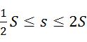
在其他示例中,多光束元件的尺寸係大於視像像素的尺寸的約百分之六十(60%),或約百分之七十(70%),或大於視像像素的尺寸的約百分之八十(80%),或大於視像像素的尺寸的約百分之九十(90%),且多光束元件係小於視像像素的尺寸的約百分之一百八十(180%),或小於視像像素的尺寸的約百分之一百六十(160%),或小於視像像素的尺寸的約百分之一百四十(140%),或小於視像像素的尺寸的約百分之一百二十(114%)。例如,藉由「可比較的尺寸」,多光束元件的尺寸可在視像像素的尺寸的約百分之七十五(75%)及約百分之一百五十(150%)之間。在另一示例中,多光束元件114在尺寸上可以與視像像素相當,其中,多光束元件的尺寸係在視像像素的尺寸的約百分之一百二十五(125%)至百分之八十五(85%)之間。根據一些實施例,可以將減少或者在一些示例中將多視像影像的視像之間的暗區域最小化為目的,來選擇多光束元件114及視像像素(或光閥116)的可比較尺寸,同時,可以減少多視像顯示器的不同視像之間的重疊,或在一些示例中將其最小化。In other examples, the size of the multi-beam element is greater than about sixty percent (60%) of the size of the video pixel, or about seventy percent (70%), or more than about the size of the video pixel. Eighty percent (80%), or greater than about ninety percent (90%) of the size of the video pixel, and the multi-beam element is smaller than about one hundred and eighty percent of the size of the video pixel ( 180%), or less than about one hundred and sixty percent (160%) of the size of the video pixel, or less than about one hundred and forty percent (140%) of the size of the video pixel, or less than the video About one hundred and twenty percent (114%) of the pixel size. For example, with "comparable size", the size of the multi-beam element can be between about seventy-five percent (75%) and about one hundred fifty percent (150%) of the size of the video pixel . In another example, the size of the
如圖6A至圖6C所示,多光束元件式顯示器110進一步包括光閥116的陣列(或光閥陣列)。光閥116的陣列用以調變複數條方向性光束中的方向性光束111。具體來說,光閥陣列可用以將方向性光束111調變為由多光束元件式顯示器110顯示的影像,例如多視像影像。在圖6C中,光閥116的陣列被部分地切除以允許導光體112與光閥陣列下方的多光束元件114的可視化。As shown in FIGS. 6A to 6C, the
具有不同主要角度方向的方向性光束111中的不同方向性光束,配置為穿過光閥陣列中的不同光閥116,並因此被不同光閥116調變。此外,如圖中所示,陣列中的光閥116對與視像像素對應,而光閥陣列中的一組光閥116與多光束元件式顯示器110的多視像像素對應。具體來說,光閥陣列中一組不同的光閥116用以接收並調變來自不同的複數個多光束元件114中的不同的多光束元件的方向性光束111。因此,如圖所示,每個多光束元件114有一組獨特的光閥116。在各種實施例中,不同種類的光閥中的任何一種可被用作該光閥陣列的複數個光閥116,其種類包含但不限於,複數個液晶光閥、複數個電泳光閥、以及基於或使用電潤濕的複數個光閥中的其中一者或多者。The different directional light beams among the directional
如圖所示,圖6A示出了第一光閥組116-1,配置為從第一多光束元件114-1接收並調變方向性光束111,而第二光閥組116-2配置為從第二多光束元件114-2接收並調變方向性光束111。因此,如圖6A中所示,光閥陣列中的複數個光閥組的每一組(例如,第一光閥組116-1及第二光閥組116-2)分別對應於不同的多視像像素,其中,複數個光閥組中的單獨光閥116與相應多視像像素的視像像素對應。As shown in the figure, FIG. 6A shows the first light valve group 116-1, which is configured to receive and modulate the directional
應注意的是,在圖6A中,視像像素的尺寸可對應於光閥陣列中的光閥116的實際尺寸。在其他示例中,視像像素的尺寸或等效的光閥尺寸可被定義為光閥陣列中相鄰的複數個光閥116之間的一距離(例如,中心至中心的距離)。舉例而言,光閥116可小於光閥陣列中複數個光閥116之間的中心至中心的距離。舉例而言,視像像素的尺寸或光閥尺寸可定義為光閥116的尺寸或對應於複數個光閥116之間的中心至中心的距離的尺寸。It should be noted that in FIG. 6A, the size of the video pixel may correspond to the actual size of the
在一些實施例中,多光束元件陣列中的多光束元件114與對應的多視像像素(例如,複數組光閥116)之間的關係可以是一對一的關係。亦即,可以存在相同數量的多視像像素和多光束元件114。圖6B通過示例的方式明確地示出了一對一關係,其中,包括不同組的光閥116的每個多視像像素,皆以虛線圍繞來描繪。在其他實施例中(圖中未顯示),多視像像素與複數個多光束元件114的數量可以彼此不同。In some embodiments, the relationship between the
在一些實施例中,多光束元件陣列中的多光束元件114中相鄰的一對多光束元件之間的元件間的距離(例如,中心至中心的距離),可等於對應之複數多視像像素中相鄰的一對多視像像素之間的像素間的距離(例如,中心至中心的距離),例如,由複數個光閥組來表示。舉例而言,如圖所示,在圖6A至圖6B中,第一多光束元件114-1和第二多光束元件114-2之間的中心至中心的距離d基本上等於第一光閥組116-1與第二光閥組116-2之間的中心至中心的距離D。在另一實施例中(圖中未顯示),該對多光束元件114及對應光閥組的相對中心至中心的距離可不同,例如,多光束元件114可具有大於或小於表示多視像像素的複數個光閥組之間的間距(例如,中心至中心的距離D)的元件間的間距(即,中心至中心的距離d)。In some embodiments, the inter-element distance (for example, the center-to-center distance) between adjacent pairs of
在一些實施例中,多光束元件114的形狀可以類似於多視像像素的形狀,或者等效地,對應於多視像像素的一組光閥116(或「子陣列」)的形狀。舉例而言,多光束元件114可以具有正方形的形狀,並且多視像像素(或對應的一組光閥116的佈置)可以基本上是方形的。在另一示例中,多光束元件114可具有長方形的形狀,即,可具有大於一寬度或橫向尺寸的一長度或縱向尺寸。在此示例中,對應多光束元件114的多視像像素(或等效於該複數組光閥116的排列)可具有類似矩形的形狀。圖6B顯示正方形多光束元件114和對應的正方形多視像像素的俯視圖或平面圖,該多視像像素包括正方形的複數組光閥116。在進一步的其他示例中(圖中未顯示)中,多光束元件114和對應的多視像像素具有各種形狀,包含或至少近似,但不限於,三角形、六角形、和圓形。In some embodiments, the shape of the
此外(例如,如圖6A中所示的),根據一些實施例,每一個多光束元件114用以將方向性光束111提供至一個且只有一個多視像像素。特定來說,對於給定的一個多光束元件114,具有與多視像影像的不同視像104對應的不同主要角度方向的方向性光束111,其基本上限於單個對應的多視像像素及其視像像素,即,對應於多光束元件114的一單組光閥116(例如,如圖6A所示)。因此,多光束元件式顯示器110的每一個多光束元件114提供具有對應於多視像影像的不同視像104的一組不同主要角度方向的對應的一組方向性光束111(即,該組方向性光束111包含具有對應於每一個不同視像方向的一方向的光束)。In addition (for example, as shown in FIG. 6A), according to some embodiments, each
根據各種實施例,多光束元件114可包括用以耦合出被引導的光113的一部分的複數個不同結構中的任何一種。舉例而言,不同結構可以包含但不限於繞射光柵、微反射元件、微折射元件、或其各種組合。在一些實施例中,多光束元件114包括繞射光柵,其用以繞射地耦合出被引導的光的一部分以成為具有不同主要角度方向的複數條方向性光束111。在其他實施例中,多光束元件114包括微反射元件,其用以反射地耦合出部分被引導的光的以成為複數條方向性光束111,或者多光束元件114包括微折射元件,其用以藉由或利用折射以耦合出被引導的光的一部分以成為複數條方向性光束111 (即,折射地耦合出部分被引導的光)。According to various embodiments, the
圖7A係根據與本發明所描述的原理一致的一實施例說明在一示例中的包含多光束元件114的多光束元件式顯示器110的一部分的剖面圖。圖7B係根據與本發明所描述的原理一致的一實施例,說明在一例中的包含多光束元件114的多光束元件式顯示器110的一部分的剖面圖。具體來說,圖7A至圖7B示出了包括繞射光柵114a的多光束元件式顯示器110的多光束元件114。繞射光柵114a用以將被引導的光113的一部分繞射地耦合為複數條方向性光束111。繞射光柵114a包括複數個繞射特徵,其藉由繞射特徵間距、或繞射特徵、或光柵間距彼此隔開,該繞射特徵用以提供繞射地耦合出的部分被引導的光。根據各種實施例,繞射光柵114a中的繞射特徵的間距或光柵間距可為次波長 (即,小於被引導的光的波長)。FIG. 7A is a cross-sectional view illustrating a part of a multi-beam
在一些實施例中,多光束元件114的繞射光柵114a可以位在導光體112的表面,或者可以相鄰於導光體112的表面。舉例而言,繞射光柵114a可以位於導光體112的第一表面112’處或導光體112的第一表面112’的附近,如圖7A所示。位在導光體第一表面112’的繞射光柵114a可以是透射模式繞射光柵,其用以將部分被引導的光通過第一表面112’繞射地耦合為方向性光束111。在另一個示例中,如圖7B所示,繞射光柵114a可以位於導光體112的第二表面112”處或導光體112的第二表面112”附近。當位於第二表面112”時,繞射光柵114a可以是反射模式繞射光柵。作為反射模式繞射光柵,繞射光柵114a用以繞射部分被引導的光並且反射部分被引導的光,使其朝向第一表面112’以通過第一表面112’離開作為繞射的方向性光束111。在其他實施例中(圖中未顯示),繞射光柵可以位於導光體112的表面之間,例如作為透射模式繞射光柵和反射模式繞射光柵中的其中之一或二者。應注意,在本文描述的一些實施例中,方向性光束111的主要角度方向可以包含由於方向性光束111在導光體表面處離開導光體112而產生的折射效應。舉例而言,作為示例而非限制,圖7B示出了當方向性光束111穿過第一表面112’時由於折射係數的變化而導致方向性光束111的折射(即,彎曲)。亦參見圖10A及圖10B,如下文所描述的。In some embodiments, the
根據一些實施例,繞射光柵114a的繞射特徵可以包括彼此間隔的凹槽和脊部中的一者或兩者。凹槽或脊部可以包括導光體112的材料,例如,可以形成在導光體112的表面中。在另一個示例中,凹槽或脊部可以由除了導光材料以外的材料形成,例如在導光體112的表面上的另一種材料的膜或層。According to some embodiments, the diffraction characteristic of the
在一些實施例中,多光束元件114的繞射光柵114a是均勻繞射光柵,其中,繞射特徵間距在整個繞射光柵114a中是大致恆定或不變的。在其他實施例中,繞射光柵114a可以是啁啾式(chirped)繞射光柵。根據定義,「啁啾式」繞射光柵是一種繞射光柵,其表現或具有在啁啾式繞射光柵的範圍或長度上變化的繞射特徵的繞射間隔(亦即,光閘間距)。在一些實施例中,啁啾式繞射光柵可以具有或表現出隨距離線性變化的繞射特徵間隔的「啁啾」或變化。因此,根據定義,啁啾式繞射光柵為「線性啁啾式」繞射光柵。在其他實施例中,多光束元件114的啁啾式繞射光柵可表現出繞射特徵間距的非線性啁啾。可以使用各種非線性啁啾,包含但不限於指數啁啾、對數啁啾、或基本上不均勻或隨機但仍然單調的方式變化的啁啾。也可以使用非單調的啁啾,例如但不限於正弦啁啾、或三角形、或鋸齒啁啾。任何這些類型的啁啾的組合也可以被使用。In some embodiments, the
在一些實施例中,繞射光柵114a可包括複數個繞射光柵或等效的複數個子光柵。圖8A係根據與本發明所描述的原理一致的一實施例,說明在一示例中的包括複數個子光柵的繞射光柵114a的剖面圖。圖8B係根據與本發明所描述的原理一致的一實施例,說明在一示例中的圖8A的繞射光柵114a的平面圖;圖8A中的剖面圖可以表示例如從圖8B中所示的繞射光柵114a的子光柵的底列從左到右截取的剖面。如圖8A與圖8B所示,複數個子光柵包括在導光體112的表面上(例如,如圖所示的第二表面112”)的多光束元件114的繞射光柵114a內的第一子光柵114a-1和第二子光柵114a-2。多光束元件114的尺寸s在圖8A與圖8B示出,而多光束元件114的邊界在圖8B中用虛線以示出。In some embodiments, the
根據一些實施例,在複數個多光束元中的不同多光束元件114之間的繞射光柵114a內的子光柵的差異密度,可以用以控制由相應的不同多光束元件114繞射地散射出的複數條方向性光束111的相對強度。換言之,繞射多光束元件114可以在其中具有不同密度的繞射光柵114a,且不同密度(即,子光柵的差異密度)可以用於控制複數條方向性光束111的相對強度。具體來說,在繞射光柵114a中,具有較少子光柵的多光束元件114可以產生複數條方向性光束111,其具有比具有相對更多子光柵的另一個多光束元件114更低的強度(或光束密度)。舉例而言,可以利用多光束元件114中的位置來提供子光柵的差異密度,例如圖8B中所示之缺少或沒有設置子光柵的位置114a’。According to some embodiments, the differential density of the sub-gratings in the
圖9係根據與本發明所描述的原理一致的一實施例,說明在一示例中的一對多光束元件114的平面圖。如圖所示,該對多光束元件114中的第一多光束元件114-1在繞射光柵114a內具有比在該對多光束元件114中的第二多光束元件114-2中存在的密度更高的子光柵。具體來說,第二多光束元件114-2具有繞射光柵114a,其具有比第一多光束元件114-1更少的子光柵和更多的沒有子光柵的位置114a’。在一些實施例中,第一多光束元件114-1中的較高密度的子光柵可以提供複數條方向性光束,其具有比由第二多光束元件114-2提供的複數條方向性光束的強度更高的強度。根據一些實施例,由圖9中所示的差異子光柵密度提供的相應的複數條方向性光束的較高強度和較低強度,可以用來補償被引導的光的光強度,其在導光體內隨傳導距離而變化。作為示例而非限制,圖9還示出了具有子光柵的繞射光柵114a,所述的子光柵具有彎曲繞射特徵。FIG. 9 is a plan view illustrating a pair of
圖10A係根據與本發明所描述的原理一致的另一實施例,說明在一示例中的包含多光束元件114的多光束式顯示器110的一部分的剖面圖。圖10B係根據與本發明所描述的原理一致的一實施例,說明在一示例中的包含多光束元件114的多光束元件式顯示器110的一部分的剖面圖。具體來說,圖10A及圖10B示出包括微反射元件的多光束元件114的各種實施例。用作或在多光束元件114中的複數個微反射元件可包含但不限於,採用一反射材料或其膜的反射器(例如,反射金屬)或基於全內反射(total internal reflection, TIR)的反射器。根據一些實施例(例如,如圖10A至圖10B所示),包括微反射元件的多光束元件114可以位於導光體112的表面(例如,第二表面112”)或位於導光體112的附近。在其他的實施例中(圖中未顯示),微反射元件可以在導光體112中位於第一表面112與第二表面112之間的位置。FIG. 10A is a cross-sectional view of a part of a
舉例而言,圖10A示出了包括微反射元件114b的多光束元件114,微反射元件114b具有位於導光體112的第二表面112”附近的反射多面結構(facets)(例如,「稜鏡式(prismatic)」微反射元件)。稜鏡式微反射元件114b的多面結構用以將被引導的光113的一部分反射(即,反射地散射)出導光體112之外以作為方向性光束111。舉例而言,多面結構可以相對於被引導的光113的傳導方向傾斜或偏斜(即,具有傾斜角),以將部分被引導的光反射出導光體112。根據各種實施例,多面結構可以利用導光體112內的反射材料(例如,如圖10A所示)而形成,或者可以是第二表面112’’中的稜柱形空腔的複數個表面。在一些實施例中,當採用稜柱形空腔時,空腔表面處的折射係數變化可以提供反射(例如,TIR反射),或者形成多面結構的空腔表面可以被反射材料塗覆以提供反射。For example, FIG. 10A shows a
在另一示例中,圖10B示出了包括微反射元件114b的多光束元件114,微反射元件114b具有大致光滑的彎曲表面,例如但不限於半球形微反射元件114b。舉例而言,微反射元件114b的特定表面曲線可以用以在不同方向上反射部分被引導的光,其根據與被引導的光113接觸的彎曲表面上的入射點。如圖10A及圖10B中所示出的,作為示例而非限制,從導光體112反射地散射出來的部分被引導的光係從第一表面112’射出或離開。如同圖10A中的稜鏡式微反射元件114b,圖10B中的微反射元件114b可以是導光體112內的反射材料或形成在第二表面112’’中的空腔(例如,一半圓形空腔),如同圖10B中作為示例而非限制所示出的。做為示例而非限制的,圖10A及圖10B亦示出具有二個傳導方向115、115’的被引導的光113(即,由粗箭頭示出)。例如,利用二個傳導方向115、115’可助於對複數條方向性光束111提供對稱的主要角度方向。In another example, FIG. 10B shows a
圖11係根據與本發明所描述的原理一致的另一實施例,說明在一示例中的包含多光束元件114的多光束式顯示器110的一部分的剖面圖。具體來說,圖11示出了包括微折射元件114c的多光束元件114。根據各種實施例,微折射元件114c用以將來自導光體112的被引導的光113的一部分折射地耦合出或散射出。亦即,如圖11所示,微折射元件114c用以使用折射(例如,與繞射或反射相對的折射耦合)以將來自導光體112的部分被引導的光耦合為或散射為方向性光束111。微折射元件114c可以具有各種形狀,其包含半球形、矩形、稜柱形(即,具有斜度的多面結構)、和反向稜柱形(例如,如圖所示圖11),但不限於此。根據各種實施例,微折射元件114c可從導光體112的一表面(例如,第一表面112’)延伸或突出,如圖所示,或可為表面中的一空腔(圖中未顯示)。此外,在一些實施例中,微折射元件114c可包括導光體112的材料。在其他實施例中,微折射元件114c可包括相鄰於導光體表面的另一材料,以及在一些示例中,微折射元件114c可包括與導光體表面接觸的另一材料。FIG. 11 is a cross-sectional view of a part of a
再次參考圖6A,多光束元件式顯示器110可進一步包括光源118。根據各種實施例,光源118用以提供在導光體112內被引導的光。尤其,光源118可以位在相鄰於導光體112的入口表面或入口端(輸入端)。在本發明的各種實施例中,光源118可以包含大致任何種類的光源(例如,光學發射器),該些光源係包含一個以上的發光二極體(light emitting diodes, LEDs)或雷射(例如,雷射二極體),但其並不受限於此。在一些實施例中,光源118可以包括光學發射器,用於產生代表特定顏色之具有窄頻光譜的基本上為單色的光。具體來說,該單色光的顏色可為特定顏色空間或特定顏色模型的原色(例如,紅-綠-藍(red-green-blue, RGB)顏色模型)。在其他示例中,光源118可以是用以提供基本上寬帶或多色光的基本寬頻帶光源。例如,光源118可提供白光。在一些實施例中,光源118可以包括複數個不同的光學發射器,用於提供不同顏色的光。不同的光學發射器可以用以提供具有與不同光色中的每一個相對應的被引導的光的不同的、顏色特定的、非零值傳導角度的光。Referring again to FIG. 6A, the
在一些實施例中,光源118可進一步包括準直器(圖中未顯示)。準直器可以用於接收來自光源118的一個以上的光學發射器的大致非準直光。準直器係進一步用於將大致非準直光轉換為準直光。具體來說,根據一些實施例,準直器可提供具有非零值傳導角度並且依據預定準直因子而被準直的準直光。而且,當採用不同顏色的光學發射器時,準直器可用以提供具有不同的、顏色特定的非零值傳導角以及不同顏色特定的準直因子中的一者或兩者的準直光。準直器進一步用以將準直光束傳送到導光體112,以將其傳導為被引導的光113,如上文所述。In some embodiments, the
根據與本文所述的原理一致的一些實施例,本發明提供了近眼雙目顯示系統。圖12係根據與本發明所描述的原理一致的一實施例,說明在一示例中的近眼雙目顯示系統200的方塊圖。近眼雙目顯示系統200用以提供多視像影像202作為表示三維景象(3D)的一對立體影像,並將一對立體影像對轉送到對應的一對眼動範圍204以供用戶觀看。根據各種實施例,該對眼動範圍204彼此橫向偏移,以對應於使用者的眼睛的位置。具體來說,使用者可以在該對橫向偏移的眼動範圍204中舒服且自然的觀看多視像影像202的該對立體影像。此外,根據本發明的一些實施例,該對立體影像的多視像影像202皆可以提供3D體驗,並且可以同時解決經常與近眼立體顯示器相關聯的各種收斂-調視(convergence-accommodation)的問題。According to some embodiments consistent with the principles described herein, the present invention provides a near-eye binocular display system. FIG. 12 is a block diagram illustrating a near-eye
如圖12所示,近眼雙目顯示系統200包括一對多光束元件式顯示器210。根據各種實施例,多光束元件式顯示器210皆用以提供表示3D景象的該對立體影像的不同多視像影像202。在一些實施例中,該對多光束元件式顯示器210中的多光束元件式顯示器210之其中一者或兩者,可以大致相似於上文中針對近眼顯示器100所描述的多光束元件式顯示器110。As shown in FIG. 12, the near-eye
具體來說,如圖所示,多光束元件式顯示器210皆包括導光體212和多光束元件陣列214(例如,如圖所示)。導光體212用以將光引導為被引導的光。多光束元件陣列214用以將被引導的光的一部分散射為複數條方向性光束,其具有與不同多視像影像的視像方向對應的主要角度方向。在一些實施例中,導光體212可以大致相似於多光束元件式顯示器110的導光體112,而多光束繞射光柵214的陣列可以大致相似於多光束元件式顯示器110的多光束繞射光柵114的陣列。具體來說,多光束元件陣列214的多光束元件可以位在導光體212的表面,或者可以相鄰於導光體212的表面。此外,在一些實施例中,多光束元件陣列214中的多光束元件可以包括光學地連接至導光體以散射出被引導的光的該部分的繞射光柵、微反射元件、與微折射元件的其中一者或多者。Specifically, as shown in the figure, the
圖12中所示的多光束元件式顯示器210進一步包括光閥陣列216。光閥陣列216用以選擇性地調變複數條方向性光束中的方向性光束。根據各種實施例,選擇性調變的方向性光束可以表示所提供的多視像影像的不同視像。在一些實施例中,光閥陣列216可以大致與上述的多光束元件式顯示器110的光閥116的陣列相似。舉例而言,光閥陣列216中的光閥可包括液晶光閥。在其他的實施例中,作為示例,光閥陣列216可以包含其他種類的光閥,該些光閥可以包含電潤濕光閥、電泳光閥、上述光閥的組合、或者液晶光閥其他種類的光閥的組合,但光閥的種類並不受限於此。在一些實施例中,多光束元件陣列214的多光束元件的尺寸與多光束元件式顯示器210的光閥陣列216中的光閥的尺寸相當。The
根據一些實施例,由該對多光束元件式顯示器210所提供的該對立體影像的各種多視像影像202係包括該三維景象的複數個不同視像。作為示例,不同視像係代表了三維景象的不同視像。此外,在各種實施例中,複數條方向性光束中的方向性光束可以具有與多視像影像的視像方向對應的不同的主要角度方向。According to some embodiments, the various
圖12中所示的近眼雙目顯示系統200進一步包括雙目光學系統220。雙目光學系統220係將該對多光束元件式顯示器210所提供的該對立體影像的不同多視像影像202分別轉送至該對眼動範圍204中的對應一者處。根據各種實施例,該對眼動範圍204係彼此橫向偏移。如上文所註解,舉例而言,眼動範圍204的橫向偏移可利於使用者觀看。圖12中的垂直虛線係表示眼動範圍204之間的橫向偏移。The near-eye
在一些實施例中,儘管是以雙目的形式配置,雙目光學系統220可以大致相似於近眼顯示器100的光學系統120。尤其,雙目光學系統220係用於將該些不同視像轉送至眼動範圍204中的對應的不同位置。此外,眼動範圍204中的不同位置用以將焦距深度提示提供給近眼雙目顯示系統200的使用者。具體來說,根據的各種實施例,焦距深度提示可以對應於該對立體影像所提供的多視像影像202之間的雙目像差。In some embodiments, although configured in a binocular form, the binocular
此外,根據一些實施例,雙目光學系統220可以包括第一自由曲面稜鏡與第二自由曲面稜鏡(圖12中未顯示)。第一自由曲面稜鏡可用以將由該對多光束元件式顯示器中的第一多光束元件式顯示器210所提供的第一多視像影像202轉送到該對眼動範圍中的第一眼動範圍204。類似地,第二自由曲面稜鏡可用以將該對多光束元件式顯示器中的第二多光束元件式顯示器210所提供的第二多視像影像202轉送至該對眼動範圍中的第二眼動範圍204。在其他的實施例中(圖中未顯示),雙目光學系統220可以包括一對放大鏡(例如,與上文中所述的簡易放大鏡122相似的一對簡易放大鏡)。In addition, according to some embodiments, the binocular
在一些實施例中,近眼雙目顯示系統200配置為虛擬實境顯示系統。更具體來說,該對立體影像所提供的不同多視像影像202可以至少在眼動範圍204中用於替換實體環境中的雙目視像。在其他的實施例中,圖12中顯示的近眼雙目顯示系統200可以配置為擴增實境顯示系統。舉例而言,當用於擴增實境顯示系統時,該對立體影像所提供的不同多視像影像202可以擴增眼動範圍204中的實體環境景象,但一般來說不會取代實體環境景象。換言之,配置為擴增實境顯示系統的近眼雙目顯示系統200係將實體環境的景象與該對立體影像的光學疊加提供給使用者。此外,當配置為擴增實境顯示器時,雙目光學系統220可以進一步包括一對自由曲面補償透鏡。根據各種實施例,自由曲面補償透鏡可以用於將實體環境的影像提供至該對眼動範圍204。In some embodiments, the near-eye
根據一些實施例,如圖12所示,多光束元件式顯示器210可進一步包括光源218。光源218係用於將光提供至導光體212。在一些實施例中,光源218可包含光學準直器,其用以準直由光源218提供的光。在一些實施例中,由光源218提供的被引導的光具有預定的準直因子。根據一些實施例,光源218可以大致相似於上文中針對近眼顯示器100所描述的多光束元件式顯示器110的光源118。According to some embodiments, as shown in FIG. 12, the
根據與本說明書中所述原理一致的其他實施例,本發明係提供一種近眼顯示器的操作方法。圖13係根據與本發明所描述的原理一致的一實施例,說明在一示例中的近眼顯示器的操作方法300的流程圖。如圖13中所示,近眼顯示器的操作方法300包括步驟310,其為使用多光束元件式顯示器以提供具有複數個不同視像的多視像影像。在一些實施例中,步驟310中,用於提供多視像影像的多光束元件式顯示器可以基本上類似於上文關於近眼顯示器100所描述的多光束元件式顯示器110。According to other embodiments consistent with the principles described in this specification, the present invention provides an operating method of a near-eye display. FIG. 13 is a flowchart illustrating an
具體來說,根據各種實施例,多光束元件式顯示器包括多光束元件陣列和光閥陣列。多光束元件陣列提供複數條方向性光束,其具有與複數個不同視像的各種視像方向對應的方向。此外,光閥陣列將複數條方向性光束調變為多視像影像。Specifically, according to various embodiments, a multi-beam element type display includes a multi-beam element array and a light valve array. The multi-beam element array provides a plurality of directional light beams having directions corresponding to various viewing directions of a plurality of different views. In addition, the light valve array modulates multiple directional beams into multi-view images.
在一些實施例中,多光束元件陣列藉由使用多光束元件陣列散射出來自導光體的被引導的光的一部分以提供複數條方向性光束,以產生具有不同的主要角度方向的複數條方向性光束。在一些實施例中,使被引導的光的該部分散射的過程包括,使用包括繞射光柵的多光束元件陣列的多光束元件,以繞射地散射出被引導的光的該部分。在一些實施例中,使被引導的光的該部分散射的過程包括,使用包括微反射元件的多光束元件陣列的多光束元件,以反射地散射出被引導的光的該部分。在一些實施例中,使被引導的光的該部分散射的過程包括,使用包括微折射元件的多光束元件陣列的多光束元件,以折射地散射出被引導的光的該部分。In some embodiments, the multi-beam element array uses the multi-beam element array to scatter a part of the guided light from the light guide to provide a plurality of directional beams, so as to generate a plurality of directions with different main angle directions. Sexual beam. In some embodiments, the process of scattering the part of the guided light includes using a multi-beam element including a multi-beam element array of diffraction gratings to diffractically scatter the part of the guided light. In some embodiments, the process of scattering the portion of the guided light includes using a multi-beam element including a multi-beam element array of micro-reflective elements to reflectively scatter the portion of the guided light. In some embodiments, the process of scattering the portion of the guided light includes using a multi-beam element including a multi-beam element array of micro-refractive elements to refractically scatter the portion of the guided light.
如圖13中所示,近眼顯示器的操作方法300進一步包括步驟320,其為使用光學系統將多視像影像的該些不同視像轉送至眼動範圍。在一些實施例中,光學系統可以大致相似於上文所述的近眼顯示器100的光學系統120。具體來說,根據一些實施例,在步驟320中,將影像的不同視像轉送的步驟,係將不同視像中的不同者轉送到眼動範圍中的不同位置處,藉此將焦距深度提示提供給在觀看眼動範圍中的影像的使用者。舉例而言,焦距深度提示可以利於使用者的眼睛進行影像調視。As shown in FIG. 13, the
在一些實施例中,轉送的多視像影像可以包括三維影像,且不同視像的不同視像可以代表三維影像的不同立體視像。在一些實施例中,被轉送的影像是該對立體影像的多視像影像。此外,在一些示例中,該影像的複數個不同視像可以包含至少四個不同的視像。在一些實施例中,轉送該影像的複數個不同視像的步驟320,包括將影像放大以提供與眼動範圍相距一距離之位置的虛像,其中,該距離係對應於使用者的眼睛的正常調視範圍。在一些實施例中,將複數個不同視像轉送的步驟320提供了擴增實境顯示器及虛擬實境顯示器的其中一者或兩者的多視像影像。In some embodiments, the transmitted multi-view image may include a three-dimensional image, and different images of different views may represent different stereoscopic images of the three-dimensional image. In some embodiments, the image to be transferred is a multi-view image of the pair of stereo images. In addition, in some examples, the plurality of different views of the image may include at least four different views. In some embodiments, the
因此,本文中描述了近眼顯示器、近眼雙目顯示系統、以及近眼顯示器的操作方法的示例與實施例,其採用多光束元件式顯示器來提供影像的複數個不同視像。應該理解的是,上述示例僅僅是說明代表本文所描述的原理的許多具體示例中的一些示例。顯然,所屬技術領域中具有通常知識者可以很容易地設計出許多其他的配置,而不偏離本發明的申請專利範圍所界定的範疇。Therefore, examples and embodiments of the near-eye display, the near-eye binocular display system, and the near-eye display's operating method are described herein, which use a multi-beam element type display to provide a plurality of different views of the image. It should be understood that the foregoing examples are merely illustrative of some of the many specific examples representing the principles described herein. Obviously, those with ordinary knowledge in the technical field can easily design many other configurations without departing from the scope defined by the patent application scope of the present invention.
本申請案主張於2017年12月18日提交的第 PCT/US2017/067131號國際專利申請的優先權,其全部內容通過引用併入本文。This application claims the priority of the International Patent Application No. PCT/US2017/067131 filed on December 18, 2017, the entire content of which is incorporated herein by reference.
10‧‧‧多視像顯示器 12‧‧‧螢幕 14‧‧‧不同視像 16‧‧‧觀看方向 20‧‧‧光束 30‧‧‧繞射光柵 40‧‧‧導光體 50‧‧‧入射光束 60‧‧‧方向性光束 100‧‧‧近眼顯示器 102‧‧‧眼動範圍 104‧‧‧不同視像 106‧‧‧虛像 108‧‧‧光線 110‧‧‧多光束元件式顯示器 111‧‧‧方向性光束 112‧‧‧導光體 112’‧‧‧第一表面 112”‧‧‧第二表面 113‧‧‧被引導的光 114‧‧‧多光束元件 114-1‧‧‧第一多光束元件 114-2‧‧‧第二多光束元件 114a‧‧‧繞射光柵 114a’‧‧‧位置 114a-1‧‧‧第一子光柵 114a-2‧‧‧第二子光柵 114b‧‧‧微反射元件 114c‧‧‧微折射元件 115‧‧‧傳導方向 115’‧‧‧另一傳導方向 116‧‧‧光閥 116-1‧‧‧第一光閥組 116-2‧‧‧第二光閥組 118‧‧‧光源 120‧‧‧光學系統 122‧‧‧簡易放大鏡 124‧‧‧自由曲面稜鏡 126‧‧‧自由曲面補償透鏡 128‧‧‧部分反射器、部分反射表面 200‧‧‧近眼雙目顯示系統 202‧‧‧多視像影像 204‧‧‧眼動範圍 210‧‧‧多光束元件式顯示器 212‧‧‧導光體 214‧‧‧多光束元件、多光束元件陣列 216‧‧‧光閥、光閥陣列 218‧‧‧光源 220‧‧‧雙目光學系統 D‧‧‧中心至中心的距離 d‧‧‧中心至中心的距離 da‧‧‧正常調視範圍、正常調視距離 f‧‧‧焦距 O‧‧‧原點 S‧‧‧視像像素的尺寸 s‧‧‧多光束元件的尺寸 θ‧‧‧角度分量、仰角分量、仰角 ϕ‧‧‧角度分量、方位角分量、方位角 θi‧‧‧入射角 θm‧‧‧繞射角 σ‧‧‧角展度、準直因子 σs‧‧‧角展度10‧‧‧Multi-vision display 12‧‧‧Screen 14‧‧‧Different vision 16‧‧‧Viewing direction 20‧‧‧Beam 30‧‧‧Diffraction grating 40‧‧‧Light guide 50‧‧‧ incident Beam 60 ‧ ‧ Directional beam 100 ‧ ‧ Near-eye monitor 102 ‧ ‧ Eye movement range 104 ‧ ‧ Different vision 106 ‧ ‧ Virtual image 108 ‧ ‧ Light 110 ‧ ‧ Multi-beam element display 111 ‧ ‧Directive beam 112‧‧‧Light guide 112'‧‧‧First surface 112"‧‧‧Second surface 113‧‧‧Guide light 114‧‧‧Multi-beam element 114-1‧‧‧First Multi-beam element 114-2‧‧‧Second multi-beam element 114a‧‧‧Diffraction grating 114a'‧‧‧Position 114a-1‧‧‧First sub-grating 114a-2‧‧‧Second sub-grating 114b‧‧ ‧Micro-reflective element 114c‧‧‧Micro-refracting element 115‧‧‧Conduction direction 115'‧‧‧Another transmission direction 116‧‧‧Light valve 116-1‧‧‧First light valve group 116-2‧‧‧Second Two light valve group 118‧‧‧Light source 120‧‧‧Optical system 122‧‧‧Simple magnifying glass 124‧‧‧Free-form surface lens 126‧‧‧Free-form surface compensation lens 128‧‧‧Partial reflector, partly reflective surface 200‧ ‧‧Near-eye binocular display system 202‧‧‧Multi-view image 204‧‧‧Eye movement range 210‧‧‧Multi-beam element display 212‧‧‧Light guide 214‧‧‧Multi-beam element, multi-beam element array 216‧‧‧Light valve, light valve array 218‧‧‧Light source 220‧‧‧Binocular optical system D‧‧‧Center to center distance d‧‧‧Center to center distance da‧‧‧Normal adjustment range, Normal adjustment distance f‧‧‧focal length O‧‧‧origin S‧‧‧view pixel size s‧‧‧multi-beam element size θ‧‧‧angle component, elevation component, elevation angle ϕ‧‧‧angle component , Azimuth component, azimuth angle θi‧‧‧ incident angle θm‧‧‧ angle of diffraction σ‧‧‧ angular spread, collimation factor σ s ‧‧‧ angular spread
根據在此描述的原理的示例和實施例的各種特徵可以參考以下結合附圖的詳細描述而更容易地理解,其中相同的附圖標記表示相同的結構元件,並且其中: 圖1A係根據與在此所描述的原理一致的一實施例,說明在一示例中的多視像顯示器的透視圖。 圖1B係根據與本發明所描述的原理一致的一實施例,說明在一示例中的多視像顯示器的具有主要角度方向的光束的角度分量的示意圖。 圖2係根據與本發明所描述的原理一致的一實施例,說明在一示例中的繞射光柵的剖面圖。 圖3係根據與本發明所描述的原理一致的實施例,說明在一示例中的近眼顯示器的示例的方塊圖。 圖4係根據與本發明所描述的原理一致的實施例,說明在一示例中的近眼顯示器的光學元件的示例的示意圖。 圖5係根據與本發明所描述的原理一致的實施例,說明在一示例中的具有光學系統的近眼顯示器的示例的剖面圖,所述的光學系統包含自由曲面稜鏡。 圖6A係根據與本發明所描述的原理一致的實施例,說明在一示例中的多光束元件式顯示器的示例的剖面圖。 圖6B係根據與本發明所描述的原理一致的一實施例,說明在一示例中的多光束元件式顯示器的平面圖。 圖6C係根據與本發明所描述的原理一致的一實施例,說明在一示例中的多光束元件式顯示器的透視圖。 圖7A係根據與本發明所描述的原理一致的一實施例,說明在一示例中的包含多光束元件的多光束元件式顯示器的一部分的剖面圖。 圖7B係根據與本發明所描述的原理一致的一實施例,說明在一示例中的包含多光束元件的多光束元件式顯示器的一部分的剖面圖。 圖8A係根據與本發明所描述的原理一致的一實施例,說明在一示例中的包括複數個子光柵的繞射光柵的剖面圖。 圖8B係根據與本發明所描述的原理一致的一實施例,說明在一示例中的圖8A的繞射光柵的平面圖。 圖9係根據與本發明所描述的原理一致的一實施例,說明在一示例中的一對多光束元件的平面圖。 圖10A係根據與本發明所描述的原理一致的另一實施例,說明在一示例中的包含多光束元件的多光束式顯示器的一部分的剖面圖。 圖10B係根據與本發明所描述的原理一致的一實施例,說明在一示例中的包含多光束元件的多光束元件式顯示器的一部分的剖面圖。 圖11係根據與本發明所描述的原理一致的一實施例,說明在一示例中的包含多光束元件的多視像背光板的一部分的剖面圖。 圖12係根據與本發明所描述的原理一致的一實施例,說明在一示例中的近眼雙目顯示系統的方塊圖。 圖13係根據與本發明所描述的原理一致的一實施例,說明在一示例中的近眼顯示器的操作方法的流程圖。 一些示例和實施例具有除了上述參考附圖中所示的特徵之外的其他特徵,或代替以上參考附圖中所示的特徵的其他特徵。下面將參考上述附圖詳細描述這些和其他特徵。Various features of the examples and embodiments according to the principles described herein can be more easily understood with reference to the following detailed description in conjunction with the accompanying drawings, in which the same reference numerals denote the same structural elements, and in which: FIG. 1A is a perspective view of a multi-view display in an example according to an embodiment consistent with the principles described herein. FIG. 1B is a schematic diagram illustrating the angular components of light beams with main angular directions of a multi-view display in an example according to an embodiment consistent with the principles described in the present invention. FIG. 2 is a cross-sectional view of a diffraction grating in an example according to an embodiment consistent with the principle described in the present invention. FIG. 3 is a block diagram illustrating an example of a near-eye display in an example according to an embodiment consistent with the principles described in the present invention. FIG. 4 is a schematic diagram illustrating an example of an optical element of a near-eye display in an example according to an embodiment consistent with the principle described in the present invention. FIG. 5 is a cross-sectional view illustrating an example of a near-eye display with an optical system in an example according to an embodiment consistent with the principles described in the present invention, and the optical system includes a free-form surface ridge. 6A is a cross-sectional view illustrating an example of a multi-beam element type display in an example according to an embodiment consistent with the principles described in the present invention. 6B is a plan view illustrating a multi-beam element type display in an example according to an embodiment consistent with the principles described in the present invention. FIG. 6C is a perspective view illustrating a multi-beam element type display in an example according to an embodiment consistent with the principles described in the present invention. FIG. 7A is a cross-sectional view illustrating a part of a multi-beam element type display including a multi-beam element in an example according to an embodiment consistent with the principles described in the present invention. FIG. 7B is a cross-sectional view of a part of a multi-beam element type display including a multi-beam element according to an embodiment consistent with the principle described in the present invention. FIG. 8A illustrates a cross-sectional view of a diffraction grating including a plurality of sub-gratings in an example according to an embodiment consistent with the principle described in the present invention. FIG. 8B illustrates a plan view of the diffraction grating of FIG. 8A in an example according to an embodiment consistent with the principles described in the present invention. FIG. 9 is a plan view illustrating a pair of multi-beam elements in an example according to an embodiment consistent with the principles described in the present invention. FIG. 10A is a cross-sectional view of a part of a multi-beam display including a multi-beam element in an example according to another embodiment consistent with the principles described in the present invention. FIG. 10B is a cross-sectional view of a part of a multi-beam element type display including a multi-beam element in an example according to an embodiment consistent with the principles described in the present invention. FIG. 11 is a cross-sectional view illustrating a part of a multi-view backlight plate including multi-beam elements in an example according to an embodiment consistent with the principles described in the present invention. FIG. 12 is a block diagram illustrating a near-eye binocular display system in an example according to an embodiment consistent with the principles described in the present invention. FIG. 13 is a flowchart illustrating an operation method of a near-eye display in an example according to an embodiment consistent with the principles described in the present invention. Some examples and embodiments have other features in addition to, or in place of, the features shown in the above referenced drawings. These and other features will be described in detail below with reference to the aforementioned drawings.
100‧‧‧近眼顯示器 100‧‧‧Near Eye Display
102‧‧‧眼動範圍 102‧‧‧Eye movement range
104‧‧‧不同視像 104‧‧‧Different video
110‧‧‧多光束元件式顯示器 110‧‧‧Multi-beam element display
120‧‧‧光學系統 120‧‧‧Optical system
Claims (26)
Applications Claiming Priority (3)
| Application Number | Priority Date | Filing Date | Title |
|---|---|---|---|
| ??PCT/US17/67131 | 2017-12-18 | ||
| WOPCT/US17/67131 | 2017-12-18 | ||
| PCT/US2017/067131 WO2019125394A1 (en) | 2017-12-18 | 2017-12-18 | Multibeam element-based near-eye display, system, and method |
Publications (2)
| Publication Number | Publication Date |
|---|---|
| TW201937230A TW201937230A (en) | 2019-09-16 |
| TWI697693B true TWI697693B (en) | 2020-07-01 |
Family
ID=66992801
Family Applications (1)
| Application Number | Title | Priority Date | Filing Date |
|---|---|---|---|
| TW107145455A TWI697693B (en) | 2017-12-18 | 2018-12-17 | Multibeam element-based near-eye display, system, and method |
Country Status (8)
| Country | Link |
|---|---|
| US (1) | US20200310135A1 (en) |
| EP (1) | EP3729168A4 (en) |
| JP (1) | JP2021507320A (en) |
| KR (1) | KR20200081512A (en) |
| CN (1) | CN111556979B (en) |
| CA (1) | CA3084249C (en) |
| TW (1) | TWI697693B (en) |
| WO (1) | WO2019125394A1 (en) |
Families Citing this family (17)
| Publication number | Priority date | Publication date | Assignee | Title |
|---|---|---|---|---|
| EP3899648A4 (en) | 2018-12-20 | 2022-11-30 | LEIA Inc. | Multiview display, system, and method having shiftable convergence plane |
| EP3903147A4 (en) | 2018-12-27 | 2022-08-24 | LEIA Inc. | Multiview display, system, and method having dynamic color sub-pixels remapping |
| EP3914859A4 (en) | 2019-01-25 | 2022-11-02 | LEIA Inc. | Multi-directional backlight, multi-user multiview display, and method |
| KR102586389B1 (en) | 2019-03-14 | 2023-10-10 | 레이아 인코포레이티드 | Mode switchable backlight, privacy display and method using emitter arrays |
| CN113614446A (en) | 2019-03-17 | 2021-11-05 | 镭亚股份有限公司 | Dual viewing area backlight, dual mode display and method employing directional emitter |
| KR102586392B1 (en) | 2019-04-02 | 2023-10-10 | 레이아 인코포레이티드 | Multi-view display alignment method and system |
| WO2021006915A1 (en) * | 2019-07-11 | 2021-01-14 | Leia Inc. | Multiview backlight, display, and method having a multibeam element within a light guide |
| CA3146357A1 (en) | 2019-08-01 | 2021-02-04 | Leia Inc. | Collimated backlight, electronic display, and method employing an absorption collimator |
| JP2022553178A (en) | 2019-10-15 | 2022-12-22 | レイア、インコーポレイテッド | Privacy Mode Backlight, Privacy Display, and Method |
| CN113219656B (en) * | 2020-01-21 | 2022-12-02 | 未来(北京)黑科技有限公司 | Vehicle-mounted head-up display system |
| BR102020008029A2 (en) * | 2020-04-22 | 2021-11-03 | Furukawa Electric Latam S.A. | IDENTIFYING DEVICE FOR CONNECTION CABLES FOR TELECOMMUNICATION NETWORK CONNECTION PANELS |
| CA3198841A1 (en) | 2020-11-09 | 2022-05-12 | Leia Inc. | Horizontal parallax multiview backlight, display, and method |
| CN112987302B (en) * | 2021-02-05 | 2022-10-18 | 业成科技(成都)有限公司 | Head-mounted display device and display system thereof |
| WO2023021273A1 (en) * | 2021-08-16 | 2023-02-23 | Bae Systems Plc | Prismatic collimating device |
| EP4137862A1 (en) * | 2021-08-16 | 2023-02-22 | BAE SYSTEMS plc | Collimating device |
| CN118043727A (en) * | 2021-09-25 | 2024-05-14 | 镭亚股份有限公司 | Static color multiview display and method |
| CN114035325B (en) * | 2021-11-10 | 2023-09-01 | 西安邮电大学 | Augmented reality method and device based on diffraction beam splitter, electronic equipment and medium |
Citations (3)
| Publication number | Priority date | Publication date | Assignee | Title |
|---|---|---|---|---|
| US9639985B2 (en) * | 2013-06-24 | 2017-05-02 | Microsoft Technology Licensing, Llc | Active binocular alignment for near eye displays |
| US9753286B2 (en) * | 2010-12-24 | 2017-09-05 | Magic Leap, Inc. | Ergonomic head mounted display device and optical system |
| TW201732370A (en) * | 2016-01-16 | 2017-09-16 | 雷亞有限公司 | Multibeam diffraction grating-based head-up display |
Family Cites Families (14)
| Publication number | Priority date | Publication date | Assignee | Title |
|---|---|---|---|---|
| GB0412651D0 (en) * | 2004-06-07 | 2004-07-07 | Microsharp Corp Ltd | Autostereoscopic rear projection screen and associated display system |
| US10156722B2 (en) * | 2010-12-24 | 2018-12-18 | Magic Leap, Inc. | Methods and systems for displaying stereoscopy with a freeform optical system with addressable focus for virtual and augmented reality |
| JP5674023B2 (en) * | 2011-01-27 | 2015-02-18 | ソニー株式会社 | Light source device and display device |
| US9250445B2 (en) * | 2012-08-08 | 2016-02-02 | Carol Ann Tosaya | Multiple-pixel-beam retinal displays |
| WO2014120160A1 (en) * | 2013-01-30 | 2014-08-07 | Hewlett-Packard Development Company, L.P. | Directional grating-based backlighting |
| EP3114526B1 (en) * | 2014-03-05 | 2021-10-20 | Arizona Board of Regents on Behalf of the University of Arizona | Wearable 3d augmented reality display |
| CN104460115B (en) * | 2014-12-31 | 2017-09-01 | 苏州大学 | A kind of various visual angles pixel directing backlight module and bore hole 3D display device |
| KR102221449B1 (en) * | 2015-09-05 | 2021-02-26 | 레이아 인코포레이티드 | Multi-view display with head tracking |
| KR102274753B1 (en) * | 2015-09-05 | 2021-07-08 | 레이아 인코포레이티드 | Condensing backlight and near-eye display using same |
| CN108028917B (en) * | 2015-10-16 | 2021-06-29 | 镭亚股份有限公司 | Near-to-eye display based on multibeam diffraction grating |
| CN108604019A (en) * | 2016-01-30 | 2018-09-28 | 镭亚股份有限公司 | Backlight based on multi-beam element and the display using the backlight |
| JP2017203908A (en) * | 2016-05-12 | 2017-11-16 | コニカミノルタ株式会社 | Holographic optical element and method for producing the same |
| CA3021958C (en) * | 2016-05-23 | 2021-11-16 | Leia Inc. | Diffractive multibeam element-based backlighting |
| JP7165051B2 (en) * | 2016-06-08 | 2022-11-02 | レイア、インコーポレイテッド | Angular Subpixel Rendering Multiview Display Using Shifted Multibeam Elements |
-
2017
- 2017-12-18 EP EP17935061.6A patent/EP3729168A4/en active Pending
- 2017-12-18 CA CA3084249A patent/CA3084249C/en active Active
- 2017-12-18 WO PCT/US2017/067131 patent/WO2019125394A1/en unknown
- 2017-12-18 JP JP2020552667A patent/JP2021507320A/en not_active Withdrawn
- 2017-12-18 KR KR1020207018594A patent/KR20200081512A/en not_active Application Discontinuation
- 2017-12-18 CN CN201780097832.1A patent/CN111556979B/en active Active
-
2018
- 2018-12-17 TW TW107145455A patent/TWI697693B/en active
-
2020
- 2020-06-15 US US16/901,971 patent/US20200310135A1/en not_active Abandoned
Patent Citations (3)
| Publication number | Priority date | Publication date | Assignee | Title |
|---|---|---|---|---|
| US9753286B2 (en) * | 2010-12-24 | 2017-09-05 | Magic Leap, Inc. | Ergonomic head mounted display device and optical system |
| US9639985B2 (en) * | 2013-06-24 | 2017-05-02 | Microsoft Technology Licensing, Llc | Active binocular alignment for near eye displays |
| TW201732370A (en) * | 2016-01-16 | 2017-09-16 | 雷亞有限公司 | Multibeam diffraction grating-based head-up display |
Also Published As
| Publication number | Publication date |
|---|---|
| US20200310135A1 (en) | 2020-10-01 |
| KR20200081512A (en) | 2020-07-07 |
| TW201937230A (en) | 2019-09-16 |
| CN111556979A (en) | 2020-08-18 |
| WO2019125394A1 (en) | 2019-06-27 |
| JP2021507320A (en) | 2021-02-22 |
| CA3084249A1 (en) | 2019-06-27 |
| CA3084249C (en) | 2024-02-06 |
| EP3729168A4 (en) | 2021-07-28 |
| EP3729168A1 (en) | 2020-10-28 |
| CN111556979B (en) | 2022-06-24 |
Similar Documents
| Publication | Publication Date | Title |
|---|---|---|
| TWI697693B (en) | Multibeam element-based near-eye display, system, and method | |
| US10728533B2 (en) | Multibeam diffraction grating-based near-eye display | |
| TWI639854B (en) | Multiview display, system, and method with head tracking | |
| TWI656384B (en) | Transparent display and its operation method | |
| TWI699557B (en) | Multibeam element-based head-up display, system, and method | |
| TW201908787A (en) | Multi-beam component based backlight with microlens, multi-view display, and method of operation thereof | |
| TWI721519B (en) | Multiview display, system, and method with user tracking | |
| TW202034043A (en) | Multi-directional backlight, multi-user multiview display, and method | |
| TWI747368B (en) | Multiview backlight, display, and method having a multibeam element within a light guide | |
| TWI833750B (en) | Multiview display and method with dynamically reconfigurable multiview pixels |