TWI683280B - Method and apparatus for generating three-dimensional panoramic video - Google Patents

Method and apparatus for generating three-dimensional panoramic video Download PDF

Info

Publication number
TWI683280B
TWI683280B TW107100258A TW107100258A TWI683280B TW I683280 B TWI683280 B TW I683280B TW 107100258 A TW107100258 A TW 107100258A TW 107100258 A TW107100258 A TW 107100258A TW I683280 B TWI683280 B TW I683280B
Authority
TW
Taiwan
Prior art keywords
pixels
picture
movement
amount
pixel
Prior art date
Application number
TW107100258A
Other languages
Chinese (zh)
Other versions
TW201911239A (en
Inventor
鄭廷威
Original Assignee
威盛電子股份有限公司
Priority date (The priority date is an assumption and is not a legal conclusion. Google has not performed a legal analysis and makes no representation as to the accuracy of the date listed.)
Filing date
Publication date
Application filed by 威盛電子股份有限公司 filed Critical 威盛電子股份有限公司
Priority to CN201810306333.5A priority Critical patent/CN108520232B/en
Priority to US16/006,874 priority patent/US10643302B2/en
Publication of TW201911239A publication Critical patent/TW201911239A/en
Application granted granted Critical
Publication of TWI683280B publication Critical patent/TWI683280B/en

Links

Images

Abstract

A method and an apparatus for generating a three-dimensional (3D) panoramic video are provided. In the method, plural frames are captured from a panoramic video. Each frame is transformed into a polyhedral mapping projection comprising plural side planes, a top plane and a bottom plane. Displacements of plural pixels in the side planes are calculated by using the plural side planes of each frame, and displacements of plural pixels in the top plane and the bottom plane are calculated by using the displacements of the side planes. Then, the pixels in the side planes, the top plane and the bottom plane of each frame are shifted according the displacements of the polyhedral mapping projection to generate a shifted polyhedral mapping projection. The shifted polyhedral mapping projection is transformed into a shifted frame in a two-dimensional (2D) space. The shifted frames and corresponding frames form 3D images and the 3D images are encoded into a 3D panoramic video.

Description

立體環景影片產生方法及裝置Method and device for generating stereoscopic surrounding film

本發明是有關於一種影片產生方法及裝置,且特別是有關於一種立體環景影片產生方法及裝置。The invention relates to a method and device for generating a film, and in particular to a method and device for generating a stereoscopic surrounding film.

球面環景相機系統中主要是利用一個或多個相機拍攝沿著水平軸的360度視野(field of view,FOV)和沿著垂直軸的180度視野的球面環景影片。如此,可以捕捉到相機系統(或者預期的觀看者)周圍各個方向上的整體環境,以用於例如虛擬實境(Virtual reality,VR)應用。近年來,技術已經發展到可以將球面環景相機系統所擷取的影片在顯示設備上以立體的方式呈現。The spherical panoramic camera system mainly uses one or more cameras to shoot a 360-degree field of view (FOV) along the horizontal axis and a 180-degree spherical field of view movie along the vertical axis. In this way, the overall environment in various directions around the camera system (or the intended viewer) can be captured for use in, for example, virtual reality (Virtual Reality, VR) applications. In recent years, technology has been developed so that the film captured by the spherical surround camera system can be presented in a stereoscopic manner on the display device.

然而,大部分的球面環景影片內容僅用於二維顯示,因此,存在著將以二維球面環景影片呈現的數位內容轉換為以立體球面環景影片呈現的需求。However, most of the spherical surround video content is only used for two-dimensional display. Therefore, there is a need to convert the digital content presented in the two-dimensional spherical surround video into the three-dimensional spherical surround video.

本發明提供一種立體環景影片產生方法及裝置,其係將環景影片的圖幀投影到多面體上並計算各投影中像素的移動量,用以對像素進行平移以獲得具視差的圖幀,而可與原始圖幀結合以產生立體環景影片。The invention provides a method and a device for generating a stereoscopic surrounding film, which projects a frame of a surrounding film onto a polyhedron and calculates the amount of movement of pixels in each projection to translate the pixels to obtain a frame with parallax, It can be combined with the original frame to produce a stereoscopic surround-view movie.

本發明的立體環景影片產生方法適用於具有處理器的電子裝置,此方法是擷取環景影片中多個圖幀,並將各圖幀轉換為多面體映射投影,其中多面體映射投影包括多個側面圖、上圖及下圖。接著依據各圖幀轉換後的多面體映射投影的側面圖計算側面圖中多個像素的移動量,並依據側面圖的移動量計算多面體映射投影的上圖與下圖中多個像素的移動量。然後依據所計算的多面體映射投影的移動量,將各圖幀轉換後的多面體映射投影的側面圖、上圖及下圖中的像素平移,以生成平移多面體映射投影。最後將平移多面體映射投影轉換為具有二維空間格式的平移圖幀,並將平移圖幀與對應的圖幀組成立體影像以編碼成立體環景影片。The method for generating a three-dimensional surrounding film of the present invention is suitable for an electronic device with a processor. This method is to capture multiple frames in a surrounding film and convert each frame to a polyhedral mapping projection, wherein the polyhedral mapping projection includes multiple Side view, upper picture and lower picture. Then calculate the movement amount of multiple pixels in the side view according to the converted side view of the polyhedral map projection of each frame, and calculate the movement amount of the plurality of pixels in the upper and lower figures of the polyhedron map projection according to the movement amount of the side view. Then, according to the calculated movement amount of the polyhedral mapping projection, the pixels in the side view, upper picture and lower picture of the converted polyhedron mapping projection of each frame are translated to generate a translational polyhedron mapping projection. Finally, the translation polyhedron mapping projection is converted into a translation picture frame with a two-dimensional space format, and the translation picture frame and the corresponding picture frame are formed into a stereoscopic image to encode into a stereoscopic surrounding film.

本發明的立體環景影片產生裝置包括連接裝置、儲存裝置及處理器。其中,連接裝置連接影像來源裝置,用以自影像來源裝置接收環景影片。儲存裝置是用以儲存多個模組。處理器耦接連接裝置及儲存裝置,用以載入並執行儲存裝置中的模組,這些模組包括圖幀擷取模組、映射模組、視差計算模組、像素平移模組、轉換模組及影片編碼模組。圖幀擷取模組擷取環景影片中多個圖幀;映射模組將各圖幀轉換為多面體映射投影,其中多面體映射投影包括多個側面圖、上圖及下圖;視差計算模組取各圖幀轉換後的多面體映射投影的側面圖計算側面圖中多個像素的移動量,並依據側面圖的移動量計算多面體映射投影的上圖與下圖中多個像素的移動量;像素平移模組依據所計算的多面體映射投影的移動量,將各圖幀轉換後的多面體映射投影的側面圖、上圖及下圖中的像素平移,以生成平移多面體映射投影;轉換模組將平移多面體映射投影轉換為具有二維空間格式的平移圖幀;影片編碼模組將平移圖幀與對應的圖幀組成立體影像以編碼成立體環景影片。The stereoscopic surrounding film production device of the present invention includes a connection device, a storage device, and a processor. Wherein, the connection device is connected to the image source device to receive the surround view video from the image source device. The storage device is used to store multiple modules. The processor is coupled to the connection device and the storage device to load and execute the modules in the storage device. These modules include a frame acquisition module, a mapping module, a parallax calculation module, a pixel translation module, and a conversion module Group and video encoding module. The frame capture module captures multiple frames in the surround view film; the mapping module converts each frame into a polyhedral mapping projection, where the polyhedral mapping projection includes multiple side views, upper and lower views; parallax calculation module Take the side view of the converted polyhedron map projection of each frame to calculate the movement amount of multiple pixels in the side view, and calculate the movement amount of the multiple pixels in the upper and lower images of the polyhedron map projection according to the movement amount of the side view; pixels The translation module translates the pixels in the side view, upper picture and lower picture of the converted polyhedron mapping projection of each frame according to the calculated movement amount of the polyhedron mapping projection to generate the translational polyhedron mapping projection; the conversion module will translate The projection projection of the polyhedron is converted into a translation image frame with a two-dimensional space format; the video encoding module forms a stereoscopic image with the translation image frame and the corresponding image frame to encode into a stereoscopic surrounding film.

基於上述,本發明的立體環景影片產生方法及裝置藉由將具有二維空間格式的球面環景影片的各圖幀轉換為三維空間中多面體的映射投影,並計算該映射投影每一面像素的移動量,據以對像素進行平移,將平移後的圖幀轉回二維空間格式,藉此使平移後的圖幀與相對應的原始圖幀可組成立體環景影像而用以編碼成立體環景影片。Based on the above, the method and device for generating a three-dimensional surrounding film of the present invention converts each frame of a spherical surrounding film with a two-dimensional space format into a mapping projection of a polyhedron in three-dimensional space, and calculates the mapping projection The amount of movement, according to which the pixels are translated, and the translated picture frames are converted back to the two-dimensional space format, so that the translated picture frames and the corresponding original picture frames can form a stereoscopic surrounding image and used to encode the stereo body Surrounding video.

為讓本發明的上述特徵和優點能更明顯易懂,下文特舉實施例,並配合所附圖式作詳細說明如下。In order to make the above-mentioned features and advantages of the present invention more obvious and understandable, the embodiments are specifically described below in conjunction with the accompanying drawings for detailed description as follows.

為了將二維的球面環景影片以立體的方式呈現,本發明的裝置除了將球面環景影片中各圖幀轉換為三維空間中多面體(polyhedron)的映射投影,並計算各圖幀的側面圖中各像素的移動量外,還依據側面圖邊緣的移動量進行上圖與下圖中各像素的移動量的推算。依據上述計算或推算出來的移動量,平移各圖幀中轉換後的映射投影的側面圖、上圖及下圖中的各像素,從而獲得平移映射投影。接著,將平移映射投影轉換回具有二維空間格式的平移圖幀,並且分別將平移圖幀與相對應的原始圖幀配置於左右眼而獲得立體影像。最後,將所獲得的立體影像編碼,即可產生具立體效果的環景影片。In order to present the two-dimensional spherical surrounding film in a three-dimensional manner, the device of the present invention converts each frame in the spherical surrounding film into a mapping projection of a polyhedron in three-dimensional space, and calculates the side view of each frame In addition to the movement amount of each pixel in the figure, the movement amount of each pixel in the upper and lower pictures is also calculated based on the movement amount of the edge of the side view. According to the above-mentioned calculated or calculated movement amount, the pixels in the side view, upper picture and lower picture of the converted mapping projection in each picture frame are translated to obtain a translation mapping projection. Next, the translation map projection is converted back to a translation image frame having a two-dimensional space format, and the translation image frame and the corresponding original image frame are respectively disposed in the left and right eyes to obtain a stereoscopic image. Finally, the obtained stereoscopic image is coded to produce a surround-view movie with a stereoscopic effect.

圖1是依照本發明一實施例所繪示之立體環景影片產生裝置的方塊圖。本實施例的立體環景影片產生裝置是以圖1中的電子裝置10為例,其例如是具備運算功能的相機、攝影機、手機、個人電腦、VR頭盔(headset)、雲端伺服器或其他裝置,其中至少包括連接裝置12、儲存裝置14及處理器16,其功能分述如下:FIG. 1 is a block diagram of a three-dimensional surround-view film generating device according to an embodiment of the invention. The three-dimensional surround video production device of this embodiment takes the electronic device 10 in FIG. 1 as an example, which is, for example, a camera, camera, mobile phone, personal computer, VR headset (headset), cloud server, or other device with a computing function , Including at least the connection device 12, the storage device 14 and the processor 16, the functions are described as follows:

連接裝置12例如是通用序列匯流排(Universal Serial Bus,USB)、RS232、藍芽、無線相容認證(Wireless fidelity,Wi-Fi)等有線或無線的傳輸介面,其可用以連接影像來源裝置,從而自影像來源裝置接收影片。所述的影像來源裝置例如是可拍攝環景影片的環景相機、儲存有環景影片的硬碟或記憶卡、或是位於遠端用以儲存環景影片的伺服器,在此不設限。The connection device 12 is, for example, a universal serial bus (Universal Serial Bus, USB), RS232, Bluetooth, wireless fidelity (Wireless fidelity, Wi-Fi) and other wired or wireless transmission interfaces, which can be used to connect an image source device, Thus, the video is received from the video source device. The image source device is, for example, a surround camera capable of shooting a surround view video, a hard disk or a memory card storing the surround view video, or a server at a remote location for storing the surround view video, which is not limited here .

儲存裝置14例如是任何型態的固定式或可移動式隨機存取記憶體(random access memory,RAM)、唯讀記憶體(read-only memory,ROM)、快閃記憶體(flash memory)或類似元件或上述元件的組合。在本實施例中,儲存裝置14用以記錄圖幀擷取模組141、映射模組142、視差計算模組143、像素平移模組144、轉換模組145及影片編碼模組146。The storage device 14 is, for example, any type of fixed or removable random access memory (RAM), read-only memory (ROM), flash memory (flash memory), or Similar elements or combinations of the above elements. In this embodiment, the storage device 14 is used to record the frame capture module 141, the mapping module 142, the parallax calculation module 143, the pixel translation module 144, the conversion module 145, and the video encoding module 146.

處理器16例如是中央處理單元(Central Processing Unit,CPU),或是其他可程式化之一般用途或特殊用途的微處理器(Microprocessor)、數位訊號處理器(Digital Signal Processor,DSP)、可程式化控制器、特殊應用積體電路(Application Specific Integrated Circuits,ASIC)、可程式化邏輯裝置(Programmable Logic Device,PLD)或其他類似裝置或這些裝置的組合,其與連接裝置12及儲存裝置14連接。The processor 16 is, for example, a central processing unit (Central Processing Unit, CPU), or other programmable general-purpose or special-purpose microprocessor (Microprocessor), digital signal processor (DSP), programmable Controller, Application Specific Integrated Circuits (ASIC), Programmable Logic Device (PLD) or other similar devices or a combination of these devices, which are connected to the connection device 12 and the storage device 14 .

在本實施例中,儲存在儲存裝置14中的模組例如是電腦程式,而可由處理器16載入,據以執行本實施例的立體環景影片產生的方法。以下即舉實施例說明此方法的詳細步驟。In this embodiment, the module stored in the storage device 14 is, for example, a computer program, which can be loaded by the processor 16 to execute the method of generating the stereoscopic surroundings video of this embodiment. The following examples illustrate the detailed steps of this method.

圖2是依照本發明一實施例所繪示之立體環景影片產生方法的流程圖。請同時參照圖1及圖2,本實施例的方法適用於上述圖1的電子裝置10,以下即搭配圖1中電子裝置10的各項裝置,說明本實施例立體環景影片產生方法的詳細步驟:FIG. 2 is a flowchart of a method for generating a stereoscopic surrounding film according to an embodiment of the invention. Please refer to FIG. 1 and FIG. 2 at the same time. The method of this embodiment is applicable to the electronic device 10 of FIG. 1 described below. step:

首先,由圖幀擷取模組141從連接裝置12所接收的影片中擷取多個圖幀(步驟S202)。其中,所述圖幀可以具有二維空間格式,但本發明不限於此。其中,所述的影片例如是電子裝置10自影像來源裝置接收的環景影片,所述的影像來源裝置可以是配置於電子裝置上的多個相機,用以拍攝電子裝置前方、後方等視野的影片,並將多個視野影片中相對應的圖幀拼接成例如是二維空間格式的球面環景圖幀,以完成球面環景影片。影像來源裝置也可以是電子裝置本身的儲存裝置14,用以儲存已拍攝的球面環景影片,但不限於此。First, the frame capturing module 141 extracts multiple frames from the video received by the connection device 12 (step S202). Wherein, the picture frame may have a two-dimensional space format, but the present invention is not limited to this. The video is, for example, a surround view video received by the electronic device 10 from an image source device. The image source device may be a plurality of cameras arranged on the electronic device, which are used to capture the front and rear views of the electronic device. Film, and stitch the corresponding picture frames in the multiple-view movie into spherical surrounding picture frames in a two-dimensional space format, for example, to complete the spherical surrounding movie. The image source device may also be the storage device 14 of the electronic device itself, which is used to store the shot spherical panoramic video, but it is not limited thereto.

需說明的是,在本實施例中,用以拍攝影片的多個相機例如是魚眼相機,其具有接近180度的視角,而多個視野影片可拍攝涵蓋部分重疊的影像以便拼接。在其他實施例中,相機也可以是除魚眼相機之外的相機,並且多個相機中相對應的各視野影片之間也可以是不重疊的。It should be noted that in this embodiment, the multiple cameras used to shoot the movie are, for example, fisheye cameras, which have a viewing angle close to 180 degrees, and the multiple-view movies can shoot partially overlapping images for stitching. In other embodiments, the camera may also be a camera other than a fish-eye camera, and the corresponding visual field films in multiple cameras may not overlap.

此外,在本實施例中,球面環景影片中的各圖幀是以等矩長方投影(Equirectangular projection)的格式來表示,其中等矩長方投影是將經度映射到恆定間距的垂直直線,以及緯度映射到恆定間距的水平直線。在其他實施例中,除了等矩長方投影之外,也可以是米勒圓柱投影(Miller cylindrical projection)、卡西尼投影(Cassini projection)等投影,用於表示球面環景影片中的各圖幀。In addition, in this embodiment, each frame in the spherical surround movie is expressed in the format of an equirectangular projection, where the equirectangular projection is a vertical straight line that maps longitude to a constant pitch, And the latitude is mapped to a horizontal line with constant spacing. In other embodiments, in addition to the equirectangular projection, Miller cylindrical projection, Cassini projection, and other projections may be used to represent the images in the spherical surround movie frame.

回到圖2的流程,在擷取多個圖幀後,映射模組142將球面環景影片中各圖幀轉換為多面體映射投影(步驟S204)。在一實施例中,映射模組142例如會利用立方體映射投影(Cube map),將球面環景影片中各圖幀投影到三維空間中立方體的六個方形面,並將所述投影以六個方形紋理(texture)或展開為具有六個區域的單一紋理的方式儲存。舉例來說,圖3是依照本發明一實施例所繪示之圖幀的等距長方投影對應於立方體映射投影的示意圖。請參照圖3,本實施例各圖幀的等距長方投影圖30中包含對應立方體映射投影的多個側面圖32、上圖34及下圖36的影像部分。其中,上述的多個側面圖32包括左圖322、前圖324、右圖326及後圖328。在其他實施例中,映射模組142也可以使用除了立方體之外的多面體,例如三角棱柱、六角棱柱等,以用於球面環景影片中各圖幀的環境映射投影。一般而言,球面環景影片中各圖幀可投影到包括上面、下面及多個側面的多面體上,而生成上圖、下圖及多個側面圖,其中上圖及下圖各自具有多個邊緣,且上圖/下圖的每個邊緣均對應於其中一個側面圖的上部/下部邊緣。例如,在立方體映射投影的情況下,側面圖的數量為四個,上圖及下圖的邊緣的數量皆為四個,而分別與四個側面圖的邊緣相對應。Returning to the flow of FIG. 2, after capturing multiple frames, the mapping module 142 converts each frame in the spherical surround movie into a polyhedral mapping projection (step S204 ). In an embodiment, the mapping module 142 uses, for example, a cube map projection (Cube map) to project each frame in the spherical surround movie to the six square faces of the cube in the three-dimensional space, and the projection is divided into six The square texture (texture) or expanded into a single texture with six areas is stored. For example, FIG. 3 is a schematic diagram of an equidistant rectangular projection of a frame according to an embodiment of the present invention corresponding to a cube mapping projection. Referring to FIG. 3, the equidistant rectangular projection of each frame of this embodiment in FIG. 30 includes a plurality of side view images 32, upper image 34, and lower image 36 corresponding to the cube map projection. Among them, the above-mentioned multiple side views 32 include a left picture 322, a front picture 324, a right picture 326, and a rear picture 328. In other embodiments, the mapping module 142 can also use polyhedrons other than cubes, such as triangular prisms, hexagonal prisms, etc., for the environmental mapping projection of each frame in the spherical surround movie. Generally speaking, each frame in a spherical surround movie can be projected onto a polyhedron including upper, lower, and multiple sides to generate an upper image, a lower image, and multiple side images, where the upper image and the lower image each have multiple Edge, and each edge of the upper/lower image corresponds to the upper/lower edge of one of the side views. For example, in the case of a cube map projection, the number of side images is four, and the number of edges in the upper and lower images is four, respectively corresponding to the edges of the four side images.

舉例來說,圖4A、圖4B是依照本發明一實施例所繪示之立方體映射投影的示意圖。請同時參照圖3、圖4A及圖4B,其中圖4B是立方體40的展開圖。在本實施例中,球面環景影片中各圖幀的等矩長方投影通過使用立方體40的六個面作為映射形狀的立方體映射來進行映射投影。也就是說,球面環景影片中各圖幀的等距長方投影圖30中對應的左圖322、前圖324、右圖326、後圖328、上圖34及下圖36的影像部分分別被映射投影至立方體40的六個面而生成左圖422、前圖424、右圖426、後圖428、上圖44及下圖46,並儲存為六個正方形。其中,用於實現等矩長方投影與立方體映射投影之間的轉換方法為本領域技術人員所熟知,在此不再贅述。For example, FIGS. 4A and 4B are schematic diagrams of cube mapping projections according to an embodiment of the invention. Please refer to FIG. 3, FIG. 4A and FIG. 4B at the same time, wherein FIG. 4B is an expanded view of the cube 40. In this embodiment, the equirectangular projection of each picture frame in the spherical surround movie is mapped and projected by the cube mapping using the six faces of the cube 40 as the mapped shape. That is to say, the equidistant rectangular projection of each frame in the spherical surround film is corresponding to the left image 322, the front image 324, the right image 326, the rear image 328, the upper image 34 and the lower image 36 in FIG. 30 respectively. The six planes of the cube 40 are mapped and projected to generate the left image 422, the front image 424, the right image 426, the rear image 428, the upper image 44 and the lower image 46, and stored as six squares. Among them, the method for realizing the conversion between the equirectangular projection and the cube-mapped projection is well known to those skilled in the art, and will not be repeated here.

值得注意的是,由於立方體映射是從代表每個立方體面的90度視錐體(view frustum)所定義的視點繪製景物六次而產生,因此與其他類型的映射投影相比,其像素計算可以以更線性的方式進行。另外,當要使用虛擬實境設備顯示球面環景影片時,採用立方體映射投影格式的影片可更加受到立體圖形硬體加速的支援。此外,在一實施例中,映射投影中的左圖422、前圖424、右圖426、後圖428、上圖44及下圖46是具有相同寬度(以像素為單位)的正方形。在另一實施例中,左圖422、前圖424、右圖426及後圖428的寬度W(以像素為單位)也可以是以等矩長方投影表示的球面環景影片中各圖幀的水平解析度(以像素為單位)的四分之一。然而,本發明並不限於此。在其他實施例中,其他的四邊形(tetragon)、高度或寬度也可以用於上述的左圖422、前圖424、右圖426、後圖428、上圖44及下圖46。It is worth noting that since the cube mapping is generated by drawing the scene six times from the viewpoint defined by the 90 degree view frustum representing each cube face, compared to other types of mapping projections, its pixel calculation can be Do it in a more linear way. In addition, when a virtual reality device is used to display a spherical surround view video, the video using the cube mapping projection format can be more supported by the acceleration of the solid graphics hardware. In addition, in one embodiment, the left image 422, the front image 424, the right image 426, the rear image 428, the upper image 44 and the lower image 46 in the mapping projection are squares with the same width (in pixels). In another embodiment, the width W (in pixels) of the left image 422, the front image 424, the right image 426, and the rear image 428 may also be each frame in a spherical surround movie represented by an isometric rectangular projection A quarter of the horizontal resolution (in pixels). However, the present invention is not limited to this. In other embodiments, other quadrilaterals (tetragons), heights or widths may also be used for the above-mentioned left image 422, front image 424, right image 426, rear image 428, upper image 44 and lower image 46.

回到圖2的流程,在獲得轉換後的多面體映射投影後,視差計算模組143會取各圖幀轉換後的映射投影的多個側面圖來計算側面圖中多個像素的移動量,並依據側面圖的移動量來計算映射投影的上圖與下圖中多個像素的移動量(步驟S206)。需注意的是,由於深度感知是由眼睛的水平分離視差所引起的,因此上圖和下圖(其大致與眼睛分離所在的水平面平行)的移動量應當與多個側面圖(其大致與眼睛分離所在的水平面正交)的移動量以不同方法進行計算。Returning to the process of FIG. 2, after obtaining the converted polyhedral map projection, the parallax calculation module 143 will take multiple side views of the converted map projection of each frame to calculate the movement amount of multiple pixels in the side view, and The amount of movement of the pixels in the upper and lower maps of the map projection is calculated according to the amount of movement in the side view (step S206). It should be noted that because depth perception is caused by the horizontal separation of the eyes, the amount of movement in the upper and lower pictures (which are roughly parallel to the horizontal plane where the eyes are separated) should be consistent with multiple side views (which are roughly the same as the eyes). The horizontal movement of the separation is orthogonal) and the amount of movement is calculated in different ways.

在一實施例中,為了取得球面環景影片中各圖幀每個像素的移動量,可以對球面環景影片中各圖幀轉換後的映射投影的多個側面圖進行已知的深度估計技術,例如利用相對模糊(Relative blurriness)、基於區塊匹配(Block-based matching)或光流(Optical flow)等方法,來計算側面圖中各像素的初始移動量。In one embodiment, in order to obtain the amount of movement of each pixel of each frame in the spherical surround film, a known depth estimation technique can be performed on the multiple side views of the map projection after the conversion of each frame in the spherical surround film For example, using relative blur (Relative blurriness), block-based matching (Block-based matching) or optical flow (Optical flow) and other methods to calculate the initial movement of each pixel in the side view.

在上述深度估計技術中,相對模糊法是從相機焦點的角度來看,距相機較遠的物體比較接近相機的物體模糊,因此,該方法是基於圖幀中各像素的模糊程度來計算每個像素的移動量。In the above depth estimation technique, the relative blur method refers to the object farther away from the camera from the camera focus point of view, and the object closer to the camera is blurred. Therefore, this method is based on the blur degree of each pixel in the frame to calculate each The amount of pixel movement.

在基於區塊匹配方法中,影片的一個或多個圖幀被分割成多個區塊,當前圖幀的各區塊可以與大小相同但在參考圖幀中移位的區塊進行比較。其中與最小匹配成本相關聯的確定位移可以被識別為所述區塊中的所有像素的估計移動幅度,且上述移動幅度可用來計算一個或多個圖幀中像素的移動量。例如,移動幅度較大的像素可被認定為更靠近相機。In the block-based matching method, one or more frames of the movie are divided into multiple blocks, and each block of the current frame can be compared with a block of the same size but shifted in the reference frame. The determined displacement associated with the minimum matching cost can be identified as the estimated movement amplitude of all pixels in the block, and the above movement amplitude can be used to calculate the movement amount of pixels in one or more picture frames. For example, pixels that move more can be considered closer to the camera.

另一方面,光流法可以識別物體亮度模式的移動,例如,影片中各圖幀的光流可被認為是移動場,其中每個點被指定有描述其移動的速度向量。光流技術可以包括經由亮度常數方程式(brightness constancy equation)將物件速度與基於像素梯度的亮度變化相關聯,其可以使用全面或局部的優化技術來計算一個或多個圖幀中像素的光流移動向量。合適的已知光流方法可以包括Farneback方法、Lucas-Kanade方法、主成份分析(principal component analysis,PCA)方法等。在一些實施例中,可以使用任意的光流法來計算側面圖的初始移動量。On the other hand, the optical flow method can recognize the movement of the object brightness mode. For example, the optical flow of each frame in the movie can be regarded as a moving field, where each point is assigned a velocity vector that describes its movement. Optical flow techniques can include associating object velocity with brightness changes based on pixel gradients via a brightness constancy equation, which can use comprehensive or local optimization techniques to calculate the optical flow movement of pixels in one or more frames vector. Suitable known optical flow methods may include Farneback method, Lucas-Kanade method, principal component analysis (PCA) method, and the like. In some embodiments, any optical flow method may be used to calculate the initial movement of the side view.

在本實施例中,側面圖中多個像素的移動量的計算是先計算各圖幀轉換後的映射投影的側面圖之間的光流場,其中上述的光流場表示為各圖幀轉換後的映射投影的側面圖中各像素在多個軸向上的初始移動量。接著,可選地,對初始移動量進行高斯平滑化計算而計算出平滑移動量;在一實施例中,上述的高斯平滑化計算可包括時間軸上的高斯平滑化計算或空間上的高斯平滑化計算。In this embodiment, the calculation of the amount of movement of multiple pixels in the side view is to first calculate the optical flow field between the side views of the map projection after the conversion of each frame, where the above optical flow field is expressed as the conversion of each frame The initial amount of movement of each pixel in multiple axial directions in the side view of the rear projection projection. Then, optionally, perform Gaussian smoothing calculation on the initial movement amount to calculate the smooth movement amount; in an embodiment, the above-mentioned Gaussian smoothing calculation may include Gaussian smoothing calculation on the time axis or Gaussian smoothing on space化算。 Computing.

舉例來說,圖5A及圖5B是依照本發明一實施例所繪示之球面環景影片中圖幀轉換後的映射投影的側面圖的範例。請同時參照圖5A及圖5B,圖幀50a為影片中時間T的圖幀,圖幀50b為影片中時間T+1的圖幀。在本實施例中,影片中圖幀50a的各像素與圖幀T+1的各像素之間的移動的畫素數量代表側面圖中各像素的初始移動量。其中,距離觀看者較遠的物件的像素具有較小的初始移動量,相反地,距離觀看者較近的物件的像素具有較大的初始移動量。For example, FIG. 5A and FIG. 5B are examples of side views of the mapping projection after the frame conversion in the spherical surround film according to an embodiment of the invention. Please refer to FIGS. 5A and 5B at the same time. Picture frame 50a is a picture frame at time T in the movie, and picture frame 50b is a picture frame at time T+1 in the movie. In this embodiment, the number of pixels moved between each pixel of the frame 50a and each pixel of the frame T+1 in the movie represents the initial amount of movement of each pixel in the side view. Among them, pixels of objects farther away from the viewer have a smaller initial movement amount; conversely, pixels of objects closer to the viewer have a larger initial movement amount.

詳細來說,影片中圖幀50a的每個像素(i,j)的初始移動量

Figure 02_image001
可包括歐幾里德坐標(Euclidian coordinates)中的水平移動量(
Figure 02_image003
)和垂直移動量(
Figure 02_image005
):
Figure 02_image007
In detail, the initial movement of each pixel (i, j) in the frame 50a of the movie
Figure 02_image001
It can include the amount of horizontal movement in Euclidian coordinates (Euclidian coordinates) (
Figure 02_image003
) And vertical movement (
Figure 02_image005
):
Figure 02_image007

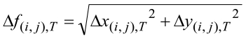
可選地,可以進一步使用高斯濾波器對初始移動量進行時間平滑化以產生平滑移動量

Figure 02_image011
,例如:
Figure 02_image013
Optionally, a Gaussian filter may be further used to perform time smoothing on the initial movement amount to generate a smooth movement amount
Figure 02_image011
,E.g:
Figure 02_image013

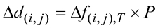
為了使像素移動量的幅度適用於不同顯示器的影像解析度,可以將初始移動量(或平滑移動量)乘以正規化(normalization)因子P,其中正規化因子P與球面環景影片中各圖幀轉換後的映射投影的側面圖的寬度W(以像素為單位)的解析度成比例,而這亦可以與如上所述的一些實施例中以等矩長方投影格式表示的球面環景影片中各圖幀的水平解析度(以像素為單位)成比例,從而得到每個像素的最終移動量

Figure 02_image017
:In order to make the magnitude of pixel movement suitable for the image resolution of different monitors, the initial movement (or smooth movement) can be multiplied by the normalization factor P, where the normalization factor P and each picture in the spherical surround movie The resolution of the width W (in pixels) of the side view of the map projection after the frame conversion is proportional to the resolution of the spherical surround view in the form of an isometric rectangular projection in some embodiments as described above The horizontal resolution (in pixels) of each frame in the image is proportional to the final movement of each pixel
Figure 02_image017
:

Figure 02_image019
Figure 02_image019

雖然最終移動量

Figure 02_image017
在下標中省略了時間T的標示,但本領域人員應當理解最終移動量也是針對各時間T進行計算。在另一實施例中,若顯示器的影像解析度剛好可配合球面環景影片中各圖幀的水平解析度,則正規化因子P可以是1,亦即最終移動量等於初始移動量。可選地,可以進一步使用例如高斯模糊濾波器對初始移動量進行空間平滑化以得到更平滑的最終移動量。且本領域技術人員應可理解,可以根據不同的情況改變執行正規化、時間平滑化及空間平滑化的順序以得到最終移動量。此外,還可以調整在時間平滑化及空間平滑化中使用的參數和/或濾波器。Although the final movement
Figure 02_image017
The indication of the time T is omitted in the subscript, but those skilled in the art should understand that the final movement amount is also calculated for each time T. In another embodiment, if the image resolution of the display just matches the horizontal resolution of each frame in the spherical surround movie, the normalization factor P may be 1, that is, the final movement amount is equal to the initial movement amount. Alternatively, a Gaussian blur filter may be further used to spatially smooth the initial movement amount to obtain a smoother final movement amount. And it should be understood by those skilled in the art that the order of performing normalization, temporal smoothing, and spatial smoothing can be changed according to different situations to obtain the final movement amount. In addition, parameters and/or filters used in temporal smoothing and spatial smoothing can also be adjusted.

舉例來說,圖6A至圖6C是依照本發明一實施例所繪示之計算移動量的範例。請參考圖6A至圖6C,影像60a是圖幀轉換後的映射投影的側面圖的光流場圖,影像60b呈現圖幀轉換後的映射投影的側面圖的初始移動量,影像60c呈現圖幀轉換後的映射投影的側面圖套用高斯模糊後的平滑移動量。For example, FIGS. 6A to 6C are examples of calculating the amount of movement according to an embodiment of the invention. Please refer to FIGS. 6A to 6C, the image 60a is the optical flow field diagram of the side view of the map projection after the frame conversion, the image 60b shows the initial movement of the side view of the map projection after the frame conversion, and the image 60c shows the frame The side map of the converted map projection applies the smooth moving amount after Gaussian blur.

視差計算模組143在計算各側面圖中每個像素的最終移動量後,取各側面圖中位於與上圖及下圖的邊界的多個邊緣像素的最終移動量計算上圖及下圖的多個邊緣像素的移動量,以及以邊緣像素的移動量作為初始值,計算上圖及下圖內其他像素的移動量。詳細來說,上圖的邊緣及下圖的邊緣(即,上圖/下圖中像素的最外側的一行)的每一行像素被指定有移動量(例如,最終移動量Δd(i,j) ),上述被指定的移動量是根據側面圖的上部和下部邊緣(即,側面圖中像素的最上面/最下面的一行)中每個相對應上圖及下圖的邊緣像素的最終移動量來計算。After calculating the final movement amount of each pixel in each side view, the parallax calculation module 143 calculates the final movement amount of a plurality of edge pixels located on the boundary with the upper and lower pictures in each side view The amount of movement of multiple edge pixels, and the amount of movement of edge pixels as the initial value, calculate the amount of movement of other pixels in the upper and lower pictures. In detail, each row of pixels of the edge of the upper picture and the edge of the lower picture (that is, the outermost row of pixels in the upper picture/lower picture) is assigned a movement amount (for example, the final movement amount Δd (i,j) ), the amount of movement specified above is based on the final amount of movement of the edge pixels in the upper and lower edges of the upper and lower edges of the side view (ie, the top/bottom row of pixels in the side view) To calculate.

舉例來說,圖7是依照本發明一實施例所繪示之圖幀的立方體映射投影。請參照圖7,本實施例立方體映射投影70是由左圖722、前圖724、右圖726、後圖728、上圖74及下圖76六個正方形所構成。在本實施例中,上圖74包括四個邊緣74a、74b、74c及74d,左圖722包括有與上圖74對應的邊緣72a及與下圖76對應的邊緣72a’,前圖724包括有與上圖74對應的邊緣72b及與下圖76對應的邊緣72b’,右圖726包括有與上圖74對應的邊緣72c及與下圖76對應的邊緣72c’,後圖728包括有與上圖74對應的邊緣72d及與下圖76對應的邊緣72d’。下圖76包括四個邊緣76a、76b、76c及76d。For example, FIG. 7 is a cube mapping projection of a picture frame according to an embodiment of the invention. Please refer to FIG. 7. In this embodiment, the cube map projection 70 is composed of six squares: a left image 722, a front image 724, a right image 726, a rear image 728, an upper image 74, and a lower image 76. In this embodiment, the upper image 74 includes four edges 74a, 74b, 74c and 74d, the left image 722 includes an edge 72a corresponding to the upper image 74 and an edge 72a' corresponding to the lower image 76, and the front image 724 includes The edge 72b corresponding to the upper image 74 and the edge 72b' corresponding to the lower image 76, the right image 726 includes the edge 72c corresponding to the upper image 74 and the edge 72c' corresponding to the lower image 76, and the rear image 728 includes the upper edge The edge 72d corresponding to FIG. 74 and the edge 72d' corresponding to the following FIG. 76. The following figure 76 includes four edges 76a, 76b, 76c, and 76d.

具體而言,在一實施例中,上圖74的邊緣74a、邊緣74b、邊緣74c及邊緣74d各像素的移動量計算方法如下所述。將左面722的邊緣72a各像素的最終移動量指定至對應的邊緣74a,以成為邊緣74a各像素的移動量;將前圖724的邊緣72b各像素的最終移動量指定至對應的邊緣,以成為邊緣74b各像素的移動量;將右圖726的邊緣72c的最終移動量指定至對應的邊緣74c,以成為邊緣74c各像素的移動量;將後圖728的邊緣72d的最終移動量指定至對應的邊緣74d,以成為邊緣74d各像素的移動量。其中,由於上圖74的四個角上的四個像素可以分別對應於兩個相鄰圖的兩個最上端頂角的像素,因此可以將兩個相鄰圖的兩個最上端頂角像素的最終移動量中任一個或者兩個最上端頂角像素的最終移動量的平均值分別指定至上述四個像素的移動量。下圖76邊緣像素的計算方法與上述上圖74類似,因此不再贅述。Specifically, in an embodiment, the method of calculating the amount of movement of each pixel of edge 74a, edge 74b, edge 74c, and edge 74d in FIG. 74 is as follows. The final movement amount of each pixel of the edge 72a of the left side 722 is assigned to the corresponding edge 74a to become the movement amount of each pixel of the edge 74a; the final movement amount of each pixel of the edge 72b of the previous figure 724 is designated to the corresponding edge to become The amount of movement of each pixel of the edge 74b; the final amount of movement of the edge 72c of the right image 726 is assigned to the corresponding edge 74c to become the amount of movement of each pixel of the edge 74c; the final amount of movement of the edge 72d of the subsequent image 728 is assigned to the corresponding The edge 74d becomes the amount of movement of each pixel in the edge 74d. Among them, since the four pixels on the four corners of the above figure 74 can correspond to the pixels of the two uppermost corners of two adjacent figures, respectively, the two uppermost corner pixels of the two adjacent figures can be The average of the final movement amounts of any one or the two topmost corner pixels of the final movement amount is assigned to the movement amounts of the above four pixels, respectively. The calculation method of the edge pixels in the lower figure 76 is similar to that in the upper figure 74, so it will not be repeated here.

視差計算模組143如此指定上圖與下圖邊緣像素的移動量之後,分別將上圖及下圖分割為多個區塊,並針對上圖及下圖中的各像素,依照所屬的區塊使用周圍多個相鄰像素的移動量計算像素的移動量。簡單來說,在確定上圖及下圖的邊緣的每行像素的移動量後,上圖及下圖的其他內部各像素可以由外到內照順序地依據其相鄰像素的移動量計算而取得。After the disparity calculation module 143 specifies the movement amount of the edge pixels in the upper and lower images in this way, the upper and lower images are divided into a plurality of blocks respectively, and for each pixel in the upper and lower images, according to the block to which they belong The amount of movement of pixels is calculated using the amount of movement of multiple neighboring pixels around. To put it simply, after determining the amount of movement of each row of pixels on the edges of the upper and lower pictures, the other internal pixels of the upper and lower pictures can be sequentially calculated from the movement of their adjacent pixels from outside to inside Made.

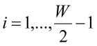
舉例來說,圖8A至圖8E是依照本發明一實施例所繪示之計算上圖移動量的範例。請參照圖8A,本實施例的立方體映射投影的上圖84被分割四個區塊I~IV,且已指定邊緣84a、邊緣84b、邊緣84c及邊緣84d各像素的移動量。接著,計算上述區塊I~IV中各區塊內部像素的移動量的方法請參照圖8B至8E。其中,圖8B的實施例中內部像素(i,j)的移動量可以根據其三個相鄰像素(例如像素(i-1,j)、像素(i-1,j-1)及像素(i,j-1))的移動量的算術平均來取得。圖8C的另一實施例中內部像素(i,j)的移動量可以根據其三個相鄰像素(例如像素(i-1,j-1)、像素(i,j-1)及像素(i+1,j-1))的移動量的算術平均來取得。圖8D的另一實施例中內部像素(i,j)的移動量可以根據其兩個相鄰像素(例如像素(i-1,j)及像素(i,j-1))的移動量的算術平均來取得。圖8E的另一實施例中內部像素(i,j)的移動量可以根據其四個相鄰像素(例如像素(i-1,j)、像素(i-1,j-1)、像素(i,j-1)及像素(i+1,j-1))的移動量的算術平均來取得。For example, FIGS. 8A to 8E are examples of calculating the amount of movement in the above figure according to an embodiment of the invention. Please refer to FIG. 8A, the above image 84 of the cube mapping projection of this embodiment is divided into four blocks I~IV, and the movement amount of each pixel of edge 84a, edge 84b, edge 84c and edge 84d has been specified. Next, please refer to FIGS. 8B to 8E for the method of calculating the amount of pixel movement in each block in the above blocks I to IV. Among them, the amount of movement of the internal pixel (i, j) in the embodiment of FIG. 8B can be based on its three adjacent pixels (for example, pixel (i-1, j), pixel (i-1, j-1), and pixel ( i, j-1)) The arithmetic average of the movement amount is obtained. In another embodiment of FIG. 8C, the movement amount of the internal pixel (i, j) may be based on its three adjacent pixels (for example, pixel (i-1, j-1), pixel (i, j-1), and pixel ( i+1, j-1)) The arithmetic average of the movement amount is obtained. In another embodiment of FIG. 8D, the amount of movement of the internal pixel (i, j) may be based on the amount of movement of its two adjacent pixels (for example, pixel (i-1, j) and pixel (i, j-1)). Arithmetic average is obtained. In another embodiment of FIG. 8E, the movement amount of the internal pixel (i, j) may be based on its four adjacent pixels (for example, pixel (i-1, j), pixel (i-1, j-1), pixel ( i, j-1) and pixel (i+1, j-1)) are obtained by arithmetic average of the movement amounts.

在本發明另一實施例中,以下述方程式來計算上述區塊I~IV的內部像素的移動量,其中i=0、i=W-1、j=0或j=W-1(W為上圖的寬度)對應於四個邊緣的像素行/列: 區塊I:

Figure 02_image023
, 其中,
Figure 02_image025
Figure 02_image027
。 區塊II:
Figure 02_image029
, 其中,
Figure 02_image031
Figure 02_image033
。 區塊III:
Figure 02_image034
, 其中,
Figure 02_image036
Figure 02_image038
。 區塊IV:
Figure 02_image040
, 其中,
Figure 02_image042
Figure 02_image044
。In another embodiment of the present invention, the amount of movement of the internal pixels in the above blocks I~IV is calculated by the following equation, where i=0, i=W-1, j=0, or j=W-1 (W is The width of the image above) corresponds to the pixel rows/columns at the four edges: Block I:
Figure 02_image023
, among them,
Figure 02_image025
And
Figure 02_image027
. Block II:
Figure 02_image029
, among them,
Figure 02_image031
And
Figure 02_image033
. Block III:
Figure 02_image034
, among them,
Figure 02_image036
And
Figure 02_image038
. Block IV:
Figure 02_image040
, among them,
Figure 02_image042
And
Figure 02_image044
.

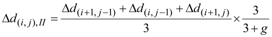
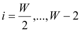
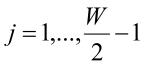
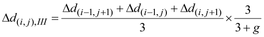
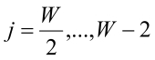
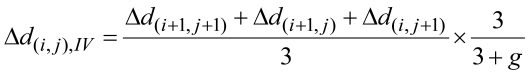
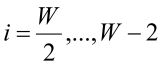
其中圖8B繪示出了在上述區塊I中各像素的計算方法所依據的三個相鄰像素的相對位置。上述方程式中的遞減參數g用於逐漸減小內部像素的移動量,使得越接近上圖中心的像素,其移動量可以越接近零,並且遞減參數g可以是0到1之間的任意數字(例如0.1)。在其他實施例中,也可以省略因子3 /(3 + g),使得移動量不會逐漸減小。FIG. 8B illustrates the relative positions of three adjacent pixels on which the calculation method of each pixel in the above block I is based. The decreasing parameter g in the above equation is used to gradually reduce the amount of movement of internal pixels, so that the closer the pixel to the center of the above figure, the closer the moving amount can be to zero, and the decreasing parameter g can be any number between 0 and 1 ( For example 0.1). In other embodiments, the factor 3 /(3 + g) may also be omitted so that the amount of movement will not gradually decrease.

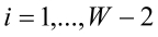
值得注意的是,圖8B至圖8E所繪示計算移動量的方法僅只是本發明的一些實施範例,並不用以限縮本發明的範疇。且在另一個實施例中,上圖84可以沿著對角線分成四個區塊如圖9所示以計算區塊I’~IV’的內部像素的移動量,也可以分為其他數量的區塊(如六個或八個區塊)。以下是計算圖9區塊I’的內部像素的移動量的另一實施例: 區塊I’:

Figure 02_image046
, 其中,
Figure 02_image048
Figure 02_image050
。It is worth noting that the methods for calculating the movement amount shown in FIGS. 8B to 8E are only some embodiments of the present invention, and are not intended to limit the scope of the present invention. And in another embodiment, the above figure 84 can be divided into four blocks along the diagonal as shown in FIG. 9 to calculate the amount of movement of the internal pixels of blocks I'~IV', or can be divided into other numbers Blocks (such as six or eight blocks). The following is another embodiment for calculating the amount of movement of internal pixels in block I'of FIG. 9: Block I':
Figure 02_image046
, among them,
Figure 02_image048
And
Figure 02_image050
.

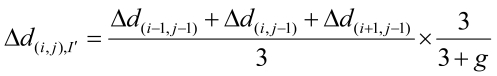
在其他實施例中,可以根據相鄰像素的移動量的幾何平均值或中值來確定內部像素的移動量。且雖然本實施例中將上圖與下圖的邊緣像素的移動量指定為相對應的側面圖的上部和下部最邊緣的一行邊緣像素的最終移動量,但在另一實施例中也可以將上圖與下圖的邊緣像素的移動量指定為相對應的側面圖的上部和下部邊緣的邊緣像素的最終移動量再乘以一常數;在又一實施例中也可以依據側面圖的上部和下部最邊緣的數個邊緣像素的最終移動量(例如是最邊緣的二個邊緣像素的最終移動量的平均值)決定相對應的上圖與下圖的邊緣像素的移動量。此外,下圖的詳細實施方式與上述上圖84類似,因此不再贅述。In other embodiments, the amount of movement of the internal pixels may be determined according to the geometric mean or median value of the amount of movement of adjacent pixels. And in this embodiment, the movement amount of the edge pixels in the upper and lower pictures is specified as the final movement amount of the edge pixels in the uppermost and lowermost rows of the corresponding side view, but in another embodiment, the movement amount The movement amount of the edge pixels in the upper picture and the lower picture is specified as the final movement amount of the edge pixels of the upper and lower edges of the corresponding side picture multiplied by a constant; in another embodiment, the upper and lower edges of the side picture can also be used The final movement amount of the edge pixels at the lowermost edge (for example, the average of the final movement amounts of the two edge pixels at the edge) determines the movement amount of the edge pixels corresponding to the upper and lower pictures. In addition, the detailed implementation of the figure below is similar to the above figure 84, so it will not be repeated here.

回到圖2的流程,在計算側面圖、上圖及下圖各像素的移動量後,可以根據各像素的移動量來確定各像素在立體球面環景影片中各圖幀的左眼和右眼圖幀之間的平移量和方向。在一實施例中,距離觀看者較遠的物件的像素應具有較小的平移量,而距離觀看者較近的物件的像素應具有較大的平移量。在一實施例中,各像素在左眼和右眼圖幀之間的平移量可以等於用前述方式所計算的各像素的移動量;在另一實施例中,各像素在左眼和右眼圖幀之間的平移量可以等於用前述方式所計算的各像素的移動量再乘以一常數,且側面圖與上圖及下圖的各像素的移動量所乘的常數可以是相同或不同。然而,各像素的平移量與所述像素的移動量之關係並不限於此。像素平移模組144依據所計算的映射投影的移動量,平移各圖幀轉換後的映射投影的側面圖、上圖及下圖中的像素,以生成平移映射投影(步驟S208)。Returning to the flow of FIG. 2, after calculating the movement amount of each pixel in the side view, the upper picture and the lower picture, the left eye and the right of each picture frame of each picture frame in the stereoscopic spherical surround film can be determined according to the movement amount of each pixel The amount and direction of translation between eye frames. In an embodiment, pixels of objects farther away from the viewer should have a smaller amount of translation, and pixels of objects closer to the viewer should have a larger amount of translation. In one embodiment, the amount of translation of each pixel between the left-eye and right-eye image frames may be equal to the amount of movement of each pixel calculated in the foregoing manner; in another embodiment, each pixel is between the left-eye and right-eye The amount of translation between frames can be equal to the amount of movement of each pixel calculated in the foregoing manner and then multiplied by a constant, and the constant multiplied by the amount of movement of each pixel in the side view and the upper and lower pictures can be the same or different . However, the relationship between the amount of translation of each pixel and the amount of movement of the pixel is not limited to this. The pixel translation module 144 translates the pixels in the side view, upper picture, and lower picture of the converted mapping projection of each frame according to the calculated amount of movement of the mapping projection to generate a translation mapping projection (step S208).

關於側面圖的平移,像素平移模組144依據側面圖的移動量平移側面圖的像素以生成平移側面圖,所述側面圖例如以水平捲繞(horizontal wraparound)方式向右平移。舉例來說,請參考圖7的立方體映射投影70,當左圖722、前圖724、右圖726及後圖728向右平移時,後圖728最右邊緣被移出的像素會被平移回補至左圖722的最左邊緣。然而,側面圖平移的方向並不限於此,例如也可以向左平移。Regarding the translation of the side view, the pixel translation module 144 translates the pixels of the side view according to the amount of movement of the side view to generate a translational side view, which is translated to the right in a horizontal wraparound manner, for example. For example, please refer to the cube mapping projection 70 of FIG. 7, when the left image 722, the front image 724, the right image 726, and the rear image 728 are shifted to the right, the pixels of the rightmost edge of the rear image 728 that are shifted out will be shifted back. To the leftmost edge of the left image 722. However, the direction of the translation of the side view is not limited to this, for example, it may be translated to the left.

關於上圖及下圖的平移,像素平移模組144依據上圖的移動量以順時針及逆時針其中之一的方向旋轉上圖中的像素以生成平移上圖,以及依據下圖的移動量以順時針及逆時針中的另一方向旋轉下圖中的像素以生成平移下圖,其中平移側面圖、平移上圖及平移下圖構成所述平移映射投影。在一實施例中,當側面圖的像素以水平捲繞方式向右平移時,上圖的像素以逆時針方向旋轉而下圖的像素以順時針方向旋轉;當側面圖的像素以水平捲繞方式向左平移時,上圖的像素以順時針方向旋轉而下圖的像素以逆時針方向旋轉。在上述旋轉的細節方面,在一實施例中,像素平移模組144分別將上圖及下圖從中心依照各邊緣分割為多個區塊(例如是三角形的區塊),並依據上圖及下圖的移動量平移各區塊內的各像素。各區塊內的各像素平移的方向可以是平行於該區塊對應的邊緣的方向,也可以是接近於以該中心為圓心的順時針或逆時針方向。其中當上圖的像素的平移跨出所屬區塊至相鄰區塊時,依相鄰區塊內的平移方向轉向以繼續在相鄰區塊內平移,當下圖的像素的平移跨出所屬區塊至相鄰區塊時,依相鄰區塊內的平移方向轉向以繼續在相鄰區塊內平移。Regarding the translation of the above picture and the following picture, the pixel translation module 144 rotates the pixels in the above picture in one of the clockwise and counterclockwise directions according to the movement amount of the above picture to generate the translation upper picture and the movement amount according to the following picture Rotate the pixels in the lower image in the other direction clockwise and counterclockwise to generate a translation lower image, where the translation side view, the translation upper image, and the translation lower image constitute the translation map projection. In one embodiment, when the pixels in the side view are shifted to the right in a horizontally-wound manner, the pixels in the upper picture are rotated counterclockwise and the pixels in the lower picture are rotated clockwise; when the pixels in the side view are wound horizontally When panning to the left, the pixels in the image above rotate clockwise and the pixels in the image below rotate counterclockwise. In terms of the details of the above rotation, in one embodiment, the pixel translation module 144 divides the upper image and the lower image from the center into multiple blocks (such as triangular blocks) according to each edge, and The amount of movement in the figure below translates each pixel within each block. The translation direction of each pixel in each block may be parallel to the corresponding edge of the block, or may be a clockwise or counterclockwise direction close to the center of the center. When the translation of the pixels in the above figure crosses out of the belonging block to the adjacent block, the direction of the translation in the adjacent block is turned to continue the translation in the adjacent block, and when the translation of the pixel in the following figure crosses the belonging area When a block reaches an adjacent block, it is turned according to the translation direction in the adjacent block to continue the translation in the adjacent block.

舉例來說,圖9是依照本發明一實施例所繪示之立方體映射投影的上圖旋轉平移的示意圖。請參照圖9的上圖94,在本實施例中,上圖94從中心沿著對角線被分割成四個三角形區塊以對應四個邊緣,包括三角形區塊942、三角形區塊944、三角形區塊946以及三角形區塊948。所述上圖依據各像素的移動量以接近於逆時針方向旋轉平移,其具體平移方式如下所述,三角形區塊942的各像素向下平移,三角形區塊944的各像素向右平移,三角形區塊946的各像素向上平移,三角形區塊948的各像素向左平移。For example, FIG. 9 is a schematic diagram of the rotation and translation of the above image of a cube mapping projection according to an embodiment of the invention. Please refer to the upper diagram 94 of FIG. 9. In this embodiment, the upper diagram 94 is divided into four triangular blocks diagonally from the center to correspond to four edges, including triangular block 942, triangular block 944, Triangle block 946 and triangle block 948. The above figure rotates and translates in a counterclockwise direction according to the amount of movement of each pixel. The specific translation method is as follows. Each pixel of the triangular block 942 is translated downward, and each pixel of the triangular block 944 is translated to the right. The triangle Each pixel of block 946 is shifted upward, and each pixel of triangle block 948 is shifted left.

需注意的是,下圖各像素的旋轉方向與上圖的旋轉方向相反。在上述實施例中,下圖各像素以接近於順時針方向旋轉平移。下圖各區塊旋轉平移的詳細實施方式與上圖94類似,因此不再贅述。然而,上圖及下圖的旋轉平移方向並不限於此。在另一實施例中,可以將上圖及下圖分割為其他數量或形狀的區塊,使得上圖及下圖以更接近逆時針或順時針方向的平移。在另一實施例中,也可以不將上圖及下圖分割為區塊而直接使用以中心為圓心的順時針或逆時針方向平移所有上圖及下圖的像素。在其他實施例中,平移之後可能發生像素缺失的情況,上述情況可以通過已知的圖像修補演算法(例如快速前進方法、Navier-Stokes方程方法等)來恢復。It should be noted that the rotation direction of each pixel in the figure below is opposite to that in the figure above. In the above embodiment, each pixel in the figure below rotates and translates in a nearly clockwise direction. The detailed implementation of the rotation and translation of each block in the following figure is similar to that in FIG. 94, so it will not be described in detail. However, the rotation and translation directions in the upper and lower diagrams are not limited to this. In another embodiment, the upper image and the lower image may be divided into blocks of other numbers or shapes, so that the upper image and the lower image are closer to the translation in the counterclockwise or clockwise direction. In another embodiment, it is also possible to directly use the clockwise or counterclockwise direction with the center as the center to translate all the pixels of the upper and lower images without dividing the upper and lower images into blocks. In other embodiments, the pixel missing may occur after the translation. The above situation can be recovered by known image repair algorithms (such as fast forward method, Navier-Stokes equation method, etc.).

回到圖2的流程,在生成平移映射投影後,轉換模組145轉換平移映射投影為具有二維空間格式的平移圖幀(步驟S210)。具體而言,在本發明一實施例中,將平移後的立方體映射投影格式的各圖幀轉換回等矩長方投影格式的圖幀。然而,上述的二維空間格式並不限於此。Returning to the flow of FIG. 2, after generating the translation map projection, the conversion module 145 converts the translation map projection into a translation map frame having a two-dimensional space format (step S210). Specifically, in an embodiment of the present invention, each picture frame in the translated cube mapping projection format is converted back to a picture frame in an equal rectangular projection format. However, the above two-dimensional space format is not limited to this.

最後,在轉換為平移圖幀後,影片編碼模組146將平移圖幀與對應的原始圖幀組成立體影像以編碼成立體影片(步驟S210)。平移圖幀的二維空間格式可以是與轉換為多面體映射投影前的原始圖幀的格式相同或不同。若平移圖幀的二維空間格式與轉換為多面體映射投影前的原始圖幀的格式不同,可以另外再將平移圖幀與對應的原始圖幀轉換成相同的二維空間格式。詳細來說,在本發明一實施例中,將球形環景影片中平移後等矩長方投影格式的圖幀以及相對應的原始等矩長方投影格式的圖幀分別作為觀看者的左眼影像和右眼影像,以提供立體影像的呈現。儘管上述實施例的平移圖幀為左眼影像、原始圖幀為右眼影像,但本領域技術人員應可理解,原始圖幀可以在相反的方向上平移以產生平移圖幀為右眼影像,而原始圖幀為左眼影像的實施方式。在一實施例中左眼影像和右眼影像可以是同步分別呈現給觀看者的左眼和右眼觀看,但本發明不限於此。Finally, after being converted into a panning frame, the video encoding module 146 forms a stereoscopic image with the panning frame and the corresponding original frame to encode a stereoscopic film (step S210). The two-dimensional spatial format of the translation image frame may be the same as or different from the format of the original image frame before conversion to the polyhedron mapping projection. If the two-dimensional spatial format of the translation image frame is different from the format of the original image frame before conversion to the polyhedral mapping projection, the translation image frame and the corresponding original image frame can be converted into the same two-dimensional space format. In detail, in an embodiment of the present invention, the frames in the isometric rectangular projection format after translation and the corresponding frames in the original isometric rectangular projection format in the spherical surround movie are respectively used as the left eye of the viewer Images and right-eye images to provide the presentation of stereoscopic images. Although the panning frame in the above embodiment is a left-eye image and the original frame is a right-eye image, those skilled in the art should understand that the original frame can be translated in the opposite direction to generate the panning frame as a right-eye image. The original image frame is an embodiment of the left-eye image. In an embodiment, the left-eye image and the right-eye image may be simultaneously displayed to the left and right eyes of the viewer, but the invention is not limited thereto.

在對球面環景影片中各圖幀進行上述映射投影、視差計算、像素平移、轉換格式及組成立體影像的步驟後,即可將各立體影像編碼並產生立體球面環景影片。由於二維空間格式(例如等矩長方投影格式)的環景影片的影像具有高度的非線性特性,故無法直接使用已知的深度估計技術計算整個影像的所有像素的移動量。本發明中先轉換環景影片為多面體映射投影格式,直接計算側面圖的移動量後再依據各側面圖的移動量計算上圖與下圖的移動量,如此可以準確且簡便地決定左眼影像和右眼影像之間的平移量以產生立體球面環景影片。After the above steps of mapping projection, parallax calculation, pixel translation, conversion format, and composition of stereo images are performed on each picture frame in the spherical surround video, each stereo image can be encoded and a stereo spherical surround video can be generated. Due to the highly non-linear nature of the images in the two-dimensional space format (such as the equirectangular projection format), it is not possible to directly use known depth estimation techniques to calculate the movement of all pixels in the entire image. In the present invention, the surround view film is first converted into a polyhedral mapping projection format, the movement amount of the side view is directly calculated, and then the movement amounts of the upper and lower pictures are calculated according to the movement amount of each side view, so that the left-eye image can be determined accurately and easily And the amount of translation between the right-eye image and the three-dimensional spherical surround film.

綜上所述,本發明的立體環景影片產生方法及裝置藉由將例如是二維空間格式的球面環景影片的各圖幀轉換為三維空間中多面體的映射投影,並對轉換後各多面體映射投影圖幀側面圖執行深度估計,計算各圖幀中側面圖的各像素的移動量,且依據側面圖的移動量計算上圖及下圖的移動量,接著依據各像素的移動量對各像素進行平移,並將平移後的多面體映射投影圖幀轉回原始圖幀的二維空間格式,藉此使平移後的圖幀與相對應的原始圖幀可產生立體環景影像以編碼成立體環景影片。In summary, the method and device for generating a three-dimensional surrounding film of the present invention converts each frame of a spherical surrounding film such as a two-dimensional space format into a mapping projection of a polyhedron in three-dimensional space, and converts each polyhedron after conversion Perform depth estimation on the side view of the map projection frame, calculate the movement amount of each pixel of the side view in each picture frame, and calculate the movement amount of the upper and lower pictures according to the movement amount of the side view, and then according to the movement amount of each pixel The pixels are translated, and the translated polyhedral mapping projection frame is converted back to the two-dimensional space format of the original frame, so that the translated frame and the corresponding original frame can generate a stereoscopic surrounding image to encode a stereoscopic image. Surrounding video.

雖然本發明已以實施例揭露如上,然其並非用以限定本發明,任何所屬技術領域中具有通常知識者,在不脫離本發明的精神和範圍內,當可作些許的更動與潤飾,故本發明的保護範圍當視後附的申請專利範圍所界定者為準。Although the present invention has been disclosed as above with examples, it is not intended to limit the present invention. Any person with ordinary knowledge in the technical field can make some changes and modifications without departing from the spirit and scope of the present invention. The scope of protection of the present invention shall be subject to the scope defined in the appended patent application.

10‧‧‧電子裝置12‧‧‧連接裝置14‧‧‧儲存裝置141‧‧‧圖幀擷取模組142‧‧‧映射模組143‧‧‧視差計算模組144‧‧‧像素平移模組145‧‧‧轉換模組146‧‧‧影片編碼模組16‧‧‧處理器30‧‧‧等距長方投影圖40‧‧‧立方體70‧‧‧立方體映射投影32‧‧‧側面圖34、44、74、84、94‧‧‧上圖36、46、76‧‧‧下圖322、422、722‧‧‧左圖324、424、724‧‧‧前圖326、426、726‧‧‧右圖328、428、728‧‧‧後圖50a、50b‧‧‧圖幀60a-60c‧‧‧影像72a-72d、72a’-72d’ 、74a-74d、76a-76d、84a-84d‧‧‧邊緣942-948‧‧‧三角形區塊S202-S210‧‧‧本發明一實施例之立體環景影片產生方法的步驟10‧‧‧Electronic device 12‧‧‧Connecting device 14‧‧‧Storage device 141‧‧‧Frame capture module 142‧‧‧ Mapping module 143‧‧‧Parallax calculation module 144‧‧‧Pixel shift module Group 145‧‧‧ conversion module 146‧‧‧ video encoding module 16‧‧‧ processor 30‧‧‧ isometric rectangular projection diagram 40‧‧‧ cube 70‧‧‧ cube mapping projection 32‧‧‧ side view 34, 44, 74, 84, 94‧‧‧ Upper picture 36, 46, 76‧‧‧ Lower picture 322, 422, 722‧‧‧ Left picture 324, 424, 724‧‧‧ Front picture 326, 426, 726‧ ‧‧ Right picture 328, 428, 728‧‧‧ Rear picture 50a, 50b‧‧‧ Frame 60a-60c ‧‧‧Edge 942-948‧‧‧triangle block S202-S210‧‧‧steps of the method for generating a stereoscopic surrounding film according to an embodiment of the invention

圖1是依照本發明一實施例所繪示之立體環景影片產生裝置的方塊圖。 圖2是依照本發明一實施例所繪示之立體環景影片產生方法的流程圖。 圖3是依照本發明一實施例所繪示之圖幀的等距長方投影對應於立方體映射投影的示意圖。 圖4A、圖4B是依照本發明一實施例所繪示之立方體映射投影的示意圖。 圖5A及圖5B是依照本發明一實施例所繪示之球面環景影片中圖幀轉換後的映射投影的側面圖的範例。 圖6A至圖6C是依照本發明一實施例所繪示之計算移動量的範例。 圖7是依照本發明一實施例所繪示之圖幀的立方體映射投影。 圖8A至圖8E是依照本發明一實施例所繪示之計算上圖移動量的範例。 圖9是依照本發明一實施例所繪示之立方體映射投影的上圖旋轉平移的示意圖。 附件是依照本發明一實施例所繪示之計算移動量過程中側面圖的範例。FIG. 1 is a block diagram of a three-dimensional surround-view film generating device according to an embodiment of the invention. FIG. 2 is a flowchart of a method for generating a stereoscopic surrounding film according to an embodiment of the invention. FIG. 3 is a schematic diagram of an equidistant rectangular projection of a picture frame corresponding to a cube mapping projection according to an embodiment of the invention. 4A and 4B are schematic diagrams of cube mapping projections according to an embodiment of the invention. FIGS. 5A and 5B are examples of side views of the mapping projection after the frame conversion in the spherical surround film according to an embodiment of the invention. 6A to 6C are examples of calculating the amount of movement according to an embodiment of the invention. 7 is a cube mapping projection of a picture frame according to an embodiment of the invention. 8A to 8E are examples of calculating the amount of movement in the above figure according to an embodiment of the invention. FIG. 9 is a schematic diagram of the rotation and translation of the above image of the cube mapping projection according to an embodiment of the invention. The attachment is an example of a side view during the calculation of the movement amount according to an embodiment of the invention.

S202-S210‧‧‧本發明一實施例之立體環景影片產生方法的步驟 S202-S210‧‧‧‧ The steps of the method for generating a stereoscopic surrounding film according to an embodiment of the invention

Claims (20)

一種立體環景影片產生方法,適用於具有處理器的電子裝置,該方法包括下列步驟: 擷取一環景影片中多個圖幀; 轉換各所述圖幀為一多面體映射投影,其中所述多面體映射投影包括多個側面圖、上圖及下圖; 依據各所述圖幀轉換後的該多面體映射投影的所述側面圖計算所述側面圖中多個像素的移動量,並依據所述側面圖的所述移動量計算該多面體映射投影的所述上圖與所述下圖中多個像素的移動量; 依據所計算的該多面體映射投影的所述移動量,平移各所述圖幀轉換後的該多面體映射投影的所述側面圖、所述上圖及所述下圖中的所述像素,以生成平移多面體映射投影;以及 轉換所述平移多面體映射投影為具有二維空間格式的平移圖幀,並將所述平移圖幀與對應的所述圖幀組成立體影像以編碼成一立體環景影片。A method for generating a three-dimensional surrounding film is suitable for an electronic device with a processor. The method includes the following steps: extracting a plurality of frames in a surrounding film; converting each of the frames into a polyhedral mapping projection, wherein the polyhedron The mapping projection includes a plurality of side images, an upper image, and a lower image; calculating the amount of movement of a plurality of pixels in the side image according to the side image of the polyhedral map projection after conversion of each of the image frames, and according to the side The movement amount of the figure calculates the movement amounts of the pixels in the upper and lower figures of the polyhedral map projection; according to the calculated movement amount of the polyhedral map projection, the frames are translated by translation The pixels of the side view, the upper picture, and the lower picture of the polyhedral mapping projection to generate a translational polyhedral mapping projection; and converting the translational polyhedral mapping projection to a translation with a two-dimensional spatial format Picture frame, and the translation picture frame and the corresponding picture frame form a stereoscopic image to encode into a stereoscopic surrounding film. 如申請專利範圍第1項所述的方法,其中依據各所述圖幀轉換後的該多面體映射投影的所述側面圖計算所述側面圖中所述像素的移動量的步驟包括: 計算各所述圖幀轉換後的該多面體映射投影的所述側面圖中各所述像素的初始移動量,並將所述初始移動量乘以正規化因子以得到各所述像素的所述移動量,其中所述正規化因子與所述環景影片中的所述圖幀的水平解析度成比例。The method according to item 1 of the patent application scope, wherein the step of calculating the amount of movement of the pixels in the side view based on the side view of the polyhedral map projection after the conversion of the respective frame includes: calculating each place The initial movement amount of each pixel in the side view of the polyhedral projection projected after the conversion of the picture frame, and the initial movement amount is multiplied by a normalization factor to obtain the movement amount of each pixel, wherein The normalization factor is proportional to the horizontal resolution of the picture frame in the surrounding movie. 如申請專利範圍第1項所述的方法,其中依據所述側面圖的所述移動量計算該多面體映射投影的所述上圖與所述下圖中所述像素的移動量的步驟包括: 依據各所述側面圖中位於與所述上圖及所述下圖的邊界的多個邊緣像素的所述移動量計算所述上圖及所述下圖中位於與各所述側面圖的邊界的多個邊緣像素的所述移動量;以及 依據所述上圖及所述下圖的所述邊緣像素的所述移動量計算所述上圖及所述下圖內其他像素的所述移動量。The method according to item 1 of the patent application scope, wherein the step of calculating the movement amount of the pixels in the upper and lower images of the polyhedral map projection according to the movement amount of the side view includes: The amount of movement of a plurality of edge pixels located at the boundary with the upper and lower pictures in each of the side views calculates the amount of movement of the edge pixels located at the boundary with each of the side views in the upper and lower pictures The movement amount of the plurality of edge pixels; and calculating the movement amount of other pixels in the upper picture and the lower picture according to the movement amount of the edge pixels of the upper picture and the lower picture. 如申請專利範圍第3項所述的方法,其中依據所述上圖及所述下圖的所述邊緣像素的所述移動量計算所述上圖及所述下圖內所述其他像素的所述移動量的步驟包括: 分別分割所述上圖及所述下圖為多個區塊,並針對所述上圖及所述下圖中的各所述像素,依照所屬的所述區塊使用各所述像素周圍多個相鄰像素的所述移動量計算該像素的所述移動量。The method according to item 3 of the patent application scope, wherein the position of the other pixels in the upper picture and the lower picture is calculated according to the movement amount of the edge pixels in the upper picture and the lower picture The step of the moving amount includes: dividing the upper picture and the lower picture into a plurality of blocks respectively, and for each pixel of the upper picture and the lower picture, according to the block to which they belong The movement amount of a plurality of adjacent pixels around each pixel calculates the movement amount of the pixel. 如申請專利範圍第4項所述的方法,其中依照所屬的所述區塊使用各所述像素周圍所述相鄰像素的所述移動量計算該像素的所述移動量的步驟包括: 依據各所述像素周圍所述相鄰像素的所述移動量及遞減參數計算該像素的所述移動量,其中所述遞減參數用於使所述上圖及所述下圖中越接近中心的內部像素的所述移動量越小。The method according to item 4 of the patent application scope, wherein the step of calculating the movement amount of the pixel using the movement amount of the neighboring pixel around each pixel according to the block to which it belongs includes: The amount of movement and decrement parameters of the neighboring pixels around the pixel calculate the amount of movement of the pixel, where the decrement parameter is used to make the upper and lower figures closer to the center of the inner pixel The smaller the amount of movement. 如申請專利範圍第1項所述的方法,其中依據所計算的該多面體映射投影的所述移動量,平移各所述圖幀轉換後的該多面體映射投影的所述側面圖、所述上圖及所述下圖中的所述像素,以生成所述平移多面體映射投影的步驟包括: 依據所述側面圖的所述移動量以水平捲繞方式向右或向左平移該側面圖的所述像素以生成平移側面圖; 依據所述上圖的所述移動量以順時針及逆時針其中之一的方向旋轉所述上圖中的所述像素以生成平移上圖;以及 依據所述下圖的所述移動量以所述順時針及逆時針中的另一方向旋轉所述下圖中的所述像素以生成平移下圖,其中所述平移側面圖、所述平移上圖及所述平移下圖構成所述平移多面體映射投影。The method according to item 1 of the patent application scope, wherein the side view and the top view of the converted polyhedral map projection after each frame conversion are translated according to the calculated movement amount of the polyhedral map projection And the pixels in the following figure to generate the translational polyhedron mapping projection includes: according to the amount of movement of the side view in a horizontally scrolling manner to the right or left to translate the side view of the side view Pixels to generate a translational side view; rotating the pixels in the upper picture in one of clockwise and counterclockwise directions according to the movement amount of the upper picture to generate a translational upper picture; and according to the lower picture The amount of movement rotates the pixels in the lower picture in the other direction of the clockwise and counterclockwise directions to generate a translation lower picture, wherein the translation side view, the translation upper picture, and the translation The following figure constitutes the mapping projection of the translational polyhedron. 如申請專利範圍第6項所述的方法,其中依據所述上圖的所述移動量以所述順時針及逆時針其中之一的方向旋轉所述上圖中的所述像素以生成所述平移上圖以及依據所述下圖的所述移動量以所述順時針及逆時針中的另一方向旋轉所述下圖中的所述像素以生成所述平移下圖的步驟包括: 將所述上圖從中心分割為多個區塊,並依據所述上圖的所述移動量平移各所述區塊內的各所述像素以接近所述順時針及逆時針其中之一的方向,其中當所述像素的平移跨出所述區塊至相鄰區塊時,依所述方向轉向以繼續在所述相鄰區塊內平移;以及 將所述下圖從中心分割為多個區塊,並依據所述下圖的所述移動量平移各所述區塊內的各所述像素以接近所述順時針及逆時針其中的另一方向,其中當所述像素的平移跨出所述區塊至相鄰區塊時,依所述另一方向轉向以繼續在所述相鄰區塊內平移。The method according to item 6 of the patent application scope, wherein the pixels in the above figure are rotated in the direction of one of the clockwise and counterclockwise directions according to the movement amount of the above figure to generate the The steps of translating the upper image and rotating the pixels in the lower image in the other direction of the clockwise and counterclockwise according to the amount of movement of the lower image to generate the translated lower image include: The above picture is divided into a plurality of blocks from the center, and the pixels in each of the blocks are translated according to the movement amount of the above picture to approach one of the clockwise and counterclockwise directions, Wherein when the translation of the pixel crosses out of the block to the adjacent block, turn in the direction to continue the translation within the adjacent block; and divide the following image from the center into multiple areas Block, and translate each of the pixels in each of the blocks according to the amount of movement in the following figure to approach the other direction of the clockwise and counterclockwise, wherein when the translation of the pixel crosses out When the block is adjacent to the adjacent block, it is turned in the other direction to continue to translate in the adjacent block. 如申請專利範圍第6項所述的方法,其中當所述側面圖的所述像素以水平捲繞方式向右平移時,所述上圖的所述像素以逆時針方向旋轉而所述下圖的所述像素以順時針方向旋轉;當所述側面圖的所述像素以水平捲繞方式向左平移時,所述上圖的所述像素以順時針方向旋轉而所述下圖的所述像素以逆時針方向旋轉。The method as described in item 6 of the patent application range, wherein when the pixels of the side view are translated to the right in a horizontal winding manner, the pixels of the upper picture are rotated counterclockwise and the lower picture Of the pixels in the clockwise direction; when the pixels in the side view are horizontally panned to the left, the pixels in the upper picture rotate in a clockwise direction and the pixels in the lower picture The pixels rotate counterclockwise. 如申請專利範圍第1項所述的方法,其中所述多面體映射投影是立方體映射投影。The method according to item 1 of the patent application scope, wherein the polyhedral mapping projection is a cube mapping projection. 如申請專利範圍第1項所述的方法,其中依據各所述圖幀轉換後的該多面體映射投影的所述側面圖計算所述側面圖中所述像素的移動量的步驟包括: 利用主成份分析光流法計算所述側面圖中所述像素的所述移動量。The method according to item 1 of the patent application scope, wherein the step of calculating the movement amount of the pixel in the side view according to the side view of the polyhedral map projection after the conversion of each of the picture frames includes: using a principal component The analysis optical flow method calculates the movement amount of the pixel in the side view. 一種立體環景影片產生裝置,包括: 連接裝置,連接影像來源裝置,以自所述影像來源裝置接收一環景影片; 儲存裝置,儲存多個模組;以及 處理器,耦接該連接裝置及該儲存裝置,載入並執行該儲存裝置中的所述模組,所述模組包括: 圖幀擷取模組,擷取所述環景影片中多個圖幀; 映射模組,轉換各所述圖幀為一多面體映射投影,其中所述多面體映射投影包括多個側面圖、上圖及下圖; 視差計算模組,取各所述圖幀轉換後的該多面體映射投影的所述側面圖計算所述側面圖中多個像素的移動量,並依據所述側面圖的所述移動量計算該多面體映射投影的所述上圖與所述下圖中多個像素的移動量; 像素平移模組,依據所計算的該多面體映射投影的所述移動量,平移各所述圖幀轉換後的該多面體映射投影的所述側面圖、所述上圖及所述下圖中的所述像素,以生成平移多面體映射投影; 轉換模組,轉換所述平移多面體映射投影為具有二維空間格式的平移圖幀;以及 影片編碼模組,將所述平移圖幀與對應的所述圖幀組成立體影像以編碼成一立體環景影片。A three-dimensional surround view video generating device includes: a connecting device connected to an image source device to receive a surround view video from the image source device; a storage device storing a plurality of modules; and a processor coupled to the connecting device and the The storage device loads and executes the module in the storage device. The module includes: a frame extraction module that captures multiple frames in the surround view video; a mapping module that converts each location The picture frame is a polyhedron mapping projection, wherein the polyhedron mapping projection includes a plurality of side views, an upper view, and a lower view; a parallax calculation module, taking the side view of the polyhedral mapping projection after conversion of each picture frame Calculating the amount of movement of a plurality of pixels in the side view, and calculating the amount of movement of the plurality of pixels in the upper and lower figures of the polyhedral mapping projection according to the movement amount of the side view; Group, according to the calculated amount of movement of the polyhedral mapping projection, translate the pixels of the side view, the upper picture, and the lower picture of the transformed polyhedron mapping projection after each frame conversion, To generate a translational polyhedron mapping projection; a conversion module, converting the translational polyhedron mapping projection into a translation picture frame having a two-dimensional space format; and a video encoding module, which forms the translation picture frame and the corresponding picture frame into a stereo The image is encoded into a three-dimensional surround view film. 如申請專利範圍第11項所述的裝置,其中所述視差計算模組包括計算各所述圖幀轉換後的該多面體映射投影的所述側面圖中各所述像素的初始移動量,並將所述初始移動量乘以正規化因子以得到各所述像素的所述移動量,其中所述正規化因子與所述環景影片中的所述圖幀的水平解析度成比例。The device according to item 11 of the patent application scope, wherein the parallax calculation module includes calculating the initial movement amount of each pixel in the side view in the side view projected by the polyhedral map projected by each of the frame conversions, and The initial movement amount is multiplied by a normalization factor to obtain the movement amount of each pixel, wherein the normalization factor is proportional to the horizontal resolution of the picture frame in the surrounding movie. 如申請專利範圍第11項所述的裝置,其中所述視差計算模組包括依據各所述側面圖中位於與所述上圖及所述下圖的邊界的多個邊緣像素的所述移動量計算所述上圖及所述下圖中位於與各所述側面圖的邊界的多個邊緣像素的所述移動量,以及依據所述上圖及所述下圖的所述邊緣像素的所述移動量計算所述上圖及所述下圖內其他像素的所述移動量。The device according to item 11 of the patent application scope, wherein the parallax calculation module includes the amount of movement of a plurality of edge pixels located on a boundary with the upper and lower images in each of the side views Calculating the amount of movement of a plurality of edge pixels located at the boundary with each of the side views in the upper and lower pictures, and the movement of the edge pixels according to the upper and lower pictures The movement amount calculates the movement amount of other pixels in the upper picture and the lower picture. 如申請專利範圍第13項所述的裝置,其中所述視差計算模組更分別分割所述上圖及所述下圖為多個區塊,並針對所述上圖及所述下圖中的各所述像素,依照所屬的所述區塊使用各所述像素周圍多個相鄰像素的所述移動量計算該像素的所述移動量。The device according to item 13 of the patent application scope, wherein the disparity calculation module further divides the upper graph and the lower graph into a plurality of blocks, and targets the upper graph and the lower graph For each pixel, the movement amount of the pixel is calculated using the movement amounts of a plurality of adjacent pixels around each pixel according to the block to which it belongs. 如申請專利範圍第14項所述的裝置,其中所述視差計算模組更依據各所述像素周圍所述相鄰像素的所述移動量及遞減參數計算該像素的所述移動量,其中所述遞減參數用於使所述上圖及所述下圖中越接近中心的內部像素的所述移動量越小。The device according to item 14 of the patent application scope, wherein the parallax calculation module further calculates the movement amount of the pixel according to the movement amount and the decrement parameter of the adjacent pixel around each pixel, wherein The decrement parameter is used to make the amount of movement of the internal pixels closer to the center in the upper and lower graphs smaller. 如申請專利範圍第11項所述的裝置,其中像素平移模組包括依據所述側面圖的所述移動量以水平捲繞方式向右或向左平移該側面圖的所述像素以生成平移側面圖,並依據所述上圖的所述移動量以順時針及逆時針其中之一的方向旋轉所述上圖中的所述像素以生成平移上圖,以及依據所述下圖的所述移動量以所述順時針及逆時針中的另一方向旋轉所述下圖中的所述像素以生成平移下圖,其中所述平移側面圖、所述平移上圖及所述平移下圖構成所述平移多面體映射投影。The device according to item 11 of the patent application scope, wherein the pixel translation module includes horizontally scrolling the pixels of the side view to the right or left according to the amount of movement of the side view to generate a translation side A picture, and rotate the pixels in the above picture in one of clockwise and counterclockwise directions according to the movement amount of the above picture to generate a translation upper picture, and the movement according to the lower picture The amount rotates the pixels in the lower graph in the other direction in the clockwise and counterclockwise directions to generate a panning lower graph, wherein the panning side view, the panning upper graph, and the panning lower graph constitute The translation polyhedron mapping projection. 如申請專利範圍第16項所述的裝置,其中像素平移模組更將所述上圖從中心分割為多個區塊,並依據所述上圖的所述移動量平移各所述區塊內的各所述像素以接近所述順時針及逆時針其中之一的方向,其中當所述像素的平移跨出所述區塊至相鄰區塊時,依所述方向轉向以繼續在所述相鄰區塊內平移;以及將所述下圖從中心分割為多個區塊,並依據所述下圖的所述移動量平移各所述區塊內的各所述像素以接近所述順時針及逆時針其中的另一方向,其中當所述像素的平移跨出所述區塊至相鄰區塊時,依所述另一方向轉向以繼續在所述相鄰區塊內平移。The device according to item 16 of the patent application scope, wherein the pixel translation module further divides the above picture from the center into a plurality of blocks, and translates each of the blocks according to the movement amount of the above picture Each of the pixels in the direction approaches one of the clockwise and counterclockwise directions, and when the translation of the pixel spans out of the block to an adjacent block, it turns in the direction to continue in the Translation within adjacent blocks; and dividing the lower graph from the center into multiple blocks, and shifting each pixel in each of the blocks according to the amount of movement of the lower graph to approach the sequential The other direction of clockwise and counterclockwise, wherein when the translation of the pixel crosses the block to the adjacent block, it is turned in the other direction to continue the translation within the adjacent block. 如申請專利範圍第16項所述的裝置,其中當所述側面圖的所述像素以水平捲繞方式向右平移時,所述上圖的所述像素以逆時針方向旋轉而所述下圖的所述像素以順時針方向旋轉;當所述側面圖的所述像素以水平捲繞方式向左平移時,所述上圖的所述像素以順時針方向旋轉而所述下圖的所述像素以逆時針方向旋轉。The device as described in claim 16 of the patent application range, wherein when the pixels of the side view are translated to the right in a horizontally-wound manner, the pixels of the upper picture rotate counterclockwise and the lower picture Of the pixels in the clockwise direction; when the pixels in the side view are horizontally panned to the left, the pixels in the upper picture rotate in a clockwise direction and the pixels in the lower picture The pixels rotate counterclockwise. 如申請專利範圍第11項所述的裝置,其中所述多面體映射投影是立方體映射投影。The device according to item 11 of the patent application scope, wherein the polyhedral mapping projection is a cubic mapping projection. 如申請專利範圍第11項所述的裝置,其中視差計算模組利用主成份分析光流法計算所述側面圖中所述像素的所述移動量移動量。The device as described in item 11 of the patent application range, wherein the parallax calculation module calculates the movement amount of the pixel in the side view using a principal component analysis optical flow method.
TW107100258A 2017-08-16 2018-01-04 Method and apparatus for generating three-dimensional panoramic video TWI683280B (en)

Priority Applications (2)

Application Number Priority Date Filing Date Title
CN201810306333.5A CN108520232B (en) 2017-08-16 2018-04-08 Method and device for generating three-dimensional panoramic film
US16/006,874 US10643302B2 (en) 2017-08-16 2018-06-13 Method and apparatus for generating three-dimensional panoramic video

Applications Claiming Priority (2)

Application Number Priority Date Filing Date Title
US201762546137P 2017-08-16 2017-08-16
US62/546,137 2017-08-16

Publications (2)

Publication Number Publication Date
TW201911239A TW201911239A (en) 2019-03-16
TWI683280B true TWI683280B (en) 2020-01-21

Family

ID=66590230

Family Applications (1)

Application Number Title Priority Date Filing Date
TW107100258A TWI683280B (en) 2017-08-16 2018-01-04 Method and apparatus for generating three-dimensional panoramic video

Country Status (1)

Country Link
TW (1) TWI683280B (en)

Families Citing this family (1)

* Cited by examiner, † Cited by third party
Publication number Priority date Publication date Assignee Title
TWI763043B (en) * 2020-09-18 2022-05-01 英業達股份有限公司 Method for generating loop video

Citations (7)

* Cited by examiner, † Cited by third party
Publication number Priority date Publication date Assignee Title
CN1153362A (en) * 1995-03-29 1997-07-02 三洋电机株式会社 Methods for creating image for three-dimensional display, for calculating depth information, and for image processing using depth information
US20030020708A1 (en) * 2001-07-23 2003-01-30 Peter-Andre Redert Image processing unit for and method of generating a first output image and a second output image and image display apparatus provided with such an image processing unit
US20130100132A1 (en) * 2011-03-31 2013-04-25 Panasonic Corporation Image rendering device, image rendering method, and image rendering program for rendering stereoscopic images
CN103544725A (en) * 2013-11-19 2014-01-29 马宁 Two-dimensional stereoscopic animation making method
US20140327745A1 (en) * 2011-11-15 2014-11-06 St-Ericsson Sa Rectified Stereoscopic 3D Panoramic Picture
TWI486052B (en) * 2011-07-05 2015-05-21 Realtek Semiconductor Corp Three-dimensional image processing device and three-dimensional image processing method
US20160088287A1 (en) * 2014-09-22 2016-03-24 Samsung Electronics Company, Ltd. Image stitching for three-dimensional video

Patent Citations (7)

* Cited by examiner, † Cited by third party
Publication number Priority date Publication date Assignee Title
CN1153362A (en) * 1995-03-29 1997-07-02 三洋电机株式会社 Methods for creating image for three-dimensional display, for calculating depth information, and for image processing using depth information
US20030020708A1 (en) * 2001-07-23 2003-01-30 Peter-Andre Redert Image processing unit for and method of generating a first output image and a second output image and image display apparatus provided with such an image processing unit
US20130100132A1 (en) * 2011-03-31 2013-04-25 Panasonic Corporation Image rendering device, image rendering method, and image rendering program for rendering stereoscopic images
TWI486052B (en) * 2011-07-05 2015-05-21 Realtek Semiconductor Corp Three-dimensional image processing device and three-dimensional image processing method
US20140327745A1 (en) * 2011-11-15 2014-11-06 St-Ericsson Sa Rectified Stereoscopic 3D Panoramic Picture
CN103544725A (en) * 2013-11-19 2014-01-29 马宁 Two-dimensional stereoscopic animation making method
US20160088287A1 (en) * 2014-09-22 2016-03-24 Samsung Electronics Company, Ltd. Image stitching for three-dimensional video

Also Published As

Publication number Publication date
TW201911239A (en) 2019-03-16

Similar Documents

Publication Publication Date Title
CN108520232B (en) Method and device for generating three-dimensional panoramic film
US7570280B2 (en) Image providing method and device
EP3534336B1 (en) Panoramic image generating method and apparatus
US20170295354A1 (en) Efficient determination of optical flow between images
JP2014522591A (en) Alignment, calibration, and rendering systems and methods for square slice real-image 3D displays
KR20140100656A (en) Point video offer device using omnidirectional imaging and 3-dimensional data and method
JP2015022510A (en) Free viewpoint image imaging device and method for the same
US20100302234A1 (en) Method of establishing dof data of 3d image and system thereof
Nielsen Surround video: a multihead camera approach
US20190266802A1 (en) Display of Visual Data with a Virtual Reality Headset
CN102692806A (en) Methods for acquiring and forming free viewpoint four-dimensional space video sequence
CN111866523B (en) Panoramic video synthesis method and device, electronic equipment and computer storage medium
WO2021104308A1 (en) Panoramic depth measurement method, four-eye fisheye camera, and binocular fisheye camera
US20100158482A1 (en) Method for processing a video data set
WO2020184174A1 (en) Image processing device and image processing method
WO2018052100A1 (en) Image processing device, image processing method, and image processing program
CN114511447A (en) Image processing method, device, equipment and computer storage medium
TWI683280B (en) Method and apparatus for generating three-dimensional panoramic video
CN108450031B (en) Image capturing apparatus
Gurrieri et al. Stereoscopic cameras for the real-time acquisition of panoramic 3D images and videos
KR101163020B1 (en) Method and scaling unit for scaling a three-dimensional model
JP6595878B2 (en) Element image group generation apparatus and program thereof
CN110913199B (en) VR image transmission method
JP2014164497A (en) Information processor, image processing method and program
JP2013200840A (en) Video processing device, video processing method, video processing program, and video display device