TW202000293A - Filtration system - Google Patents

Filtration system Download PDF

Info

Publication number
TW202000293A
TW202000293A TW107119691A TW107119691A TW202000293A TW 202000293 A TW202000293 A TW 202000293A TW 107119691 A TW107119691 A TW 107119691A TW 107119691 A TW107119691 A TW 107119691A TW 202000293 A TW202000293 A TW 202000293A
Authority
TW
Taiwan
Prior art keywords
tapered portion
filtration system
outlet channel
channel
blades
Prior art date
Application number
TW107119691A
Other languages
Chinese (zh)
Other versions
TWI641414B (en
Inventor
孫正和
Original Assignee
孫正和
柳秀靜
Priority date (The priority date is an assumption and is not a legal conclusion. Google has not performed a legal analysis and makes no representation as to the accuracy of the date listed.)
Filing date
Publication date
Application filed by 孫正和, 柳秀靜 filed Critical 孫正和
Priority to TW107119691A priority Critical patent/TWI641414B/en
Application granted granted Critical
Publication of TWI641414B publication Critical patent/TWI641414B/en
Publication of TW202000293A publication Critical patent/TW202000293A/en

Links

Images

Abstract

A filtration system is provided, including: a casing, including an inlet passage and an outlet passage which are arranged on an extension line; a guiding mechanism, including a first tapering portion tapered in a direction toward the inlet passage, a second tapering portion tapered in a direction toward the outlet passage and a plurality of blades, the plurality of blades extending spirally on the first tapering portion relative to the extension line, a gap being defined between the plurality of blades and the casing, and the gap being smaller than a height of one of the blades based on a surface of the first tapering portion.

Description

過濾系統filtering system

本發明係有關於一種過濾系統。The invention relates to a filtering system.

一般過濾含塵氣體之方式,係使含塵氣體引起旋流,藉助於離心力原理,將在旋流外側流動的粉塵從含塵氣體分離。因此,裝置具有形成旋流流動空間之圓筒形的外殼及在外殼內部使含塵氣體引起旋流之導流機構。該導流機構之結構設計及其與該外殼間之配合直接影響粉塵氣體之過濾效果。然,習知之過濾裝置配置不良因而無法有效的利用氣體旋流,導致過濾效果不佳。The general method of filtering dust-containing gas is to cause the dust-containing gas to cause a swirling flow, and the dust flowing outside the swirling flow is separated from the dust-containing gas by virtue of the centrifugal force principle. Therefore, the device has a cylindrical casing that forms a swirling flow space and a flow guide mechanism that causes a dusty gas to swirl inside the casing. The structural design of the diversion mechanism and its cooperation with the housing directly affect the filtering effect of the dust gas. However, the conventional filtering device is poorly configured and cannot effectively use the gas swirl, resulting in poor filtering effect.

因此,有必要提供一種新穎且具有進步性之過濾系統,以解決上述之問題。Therefore, it is necessary to provide a novel and progressive filter system to solve the above problems.

本發明之主要目的在於提供一種過濾系統,具高分離效率。The main purpose of the present invention is to provide a filtration system with high separation efficiency.

為達成上述目的,本發明提供一種過濾系統,包括:一殼體,包括位於同一延伸線上之一入口通道及一出口通道;一導流機構,包括一朝該入口通道方向漸縮之第一漸縮部、一朝該出口通道方向漸縮之第二漸縮部及多個葉片,該多個葉片相對於該延伸線螺旋地延伸於該第一漸縮部,該多個葉片與該殼體的內壁之間形成一間隙,該間隙小於該葉片相對該第一漸縮部之表面的一高度。In order to achieve the above object, the present invention provides a filtration system, including: a housing including an inlet channel and an outlet channel located on the same extension line; a flow guide mechanism including a first taper that tapers toward the inlet channel A reduced portion, a second tapered portion tapered toward the outlet channel, and a plurality of blades, the plurality of blades spirally extend from the first tapered portion relative to the extension line, the plurality of blades and the housing A gap is formed between the inner walls of, the gap is smaller than a height of the blade relative to the surface of the first tapered portion.

以下僅以實施例說明本發明可能之實施態樣,然並非用以限制本發明所欲保護之範疇,合先敘明。The following merely illustrates the possible implementation forms of the present invention with examples, but it is not intended to limit the scope of the invention to be protected, and will be described first.

請參考圖1至圖5,其顯示本發明之一較佳實施例,本發明之過濾系統1包括一殼體10及一導流機構20。Please refer to FIGS. 1 to 5, which show a preferred embodiment of the present invention. The filter system 1 of the present invention includes a housing 10 and a flow guiding mechanism 20.

該殼體10包括位於同一延伸線L上之一入口通道11及一出口通道12;該導流機構20包括一朝該入口通道11方向漸縮之第一漸縮部21、一朝該出口通道12方向漸縮之第二漸縮部22及多個葉片23,該多個葉片23相對於該延伸線L螺旋地延伸於該第一漸縮部21,該多個葉片23與該殼體10的內壁之間形成一間隙30,該間隙30小於該葉片23相對該第一漸縮部21之表面的一高度。該殼體10、該入口通道11、該出口通道12、該第一漸縮部21及該第二漸縮部22較佳具有圓形截面,具最低流阻及最低動能損耗。藉此可形成旋流且具高分離效率。The housing 10 includes an inlet channel 11 and an outlet channel 12 on the same extension line L; the flow guiding mechanism 20 includes a first tapered portion 21 tapered toward the inlet channel 11 and a outlet toward the outlet channel A 12-direction tapered second tapered portion 22 and a plurality of blades 23 that spirally extend from the first tapered portion 21 relative to the extension line L, the plurality of blades 23 and the housing 10 A gap 30 is formed between the inner walls of the gap, the gap 30 being smaller than a height of the blade 23 relative to the surface of the first tapered portion 21. The housing 10, the inlet channel 11, the outlet channel 12, the first tapered portion 21 and the second tapered portion 22 preferably have a circular cross section, with the lowest flow resistance and the lowest kinetic energy loss. In this way, a swirl flow can be formed with high separation efficiency.

該殼體10另包括一橫向於該延伸線L延伸之排塵通道13,該排塵通道13較佳位於該出口通道12的徑向外側、且相對於該延伸線L偏心設置,使其位於旋流外圍,可提高集塵效率。於本實施例中,該排塵通道13沿該出口通道12之徑向朝外為一方管且漸縮地連接一圓管;該排塵通道亦可整體為圓管,較不降低旋流動能且較不卡垢。然,該排塵通道亦可具有不同的截面變化。The housing 10 further includes a dust discharge channel 13 extending transverse to the extension line L. The dust discharge channel 13 is preferably located radially outward of the outlet channel 12 and is eccentrically disposed relative to the extension line L so that it is located The periphery of the cyclone can improve the dust collection efficiency. In this embodiment, the dust discharge channel 13 is a side tube along the radial direction of the outlet channel 12 and is gradually connected to a circular tube; the dust discharge channel can also be a circular tube as a whole, which does not reduce the swirling flow energy and is relatively No dirt. Of course, the dust discharge channel can also have different cross-sectional changes.

該出口通道12包括一連接該殼體10之管件121及一周設於該管件121外之擋緣122,沿該排塵通道13之一軸向觀之,該擋緣122至少部分位於該管件121範圍內。藉此,該擋緣122可防止離心分離之粉塵沿該殼體10與該管件121間之空間逆向旋流進入該出口通道12。詳細說,該擋緣122朝該出口通道12方向漸擴而呈一圓錐面。該擋緣122設有多個鰭片123,該多個鰭片123之延伸方向順向於該葉片23的螺旋方向,可有效擋止粉塵使其確實落塵進入該排塵通道13而排出。該擋緣122較佳為一體沖壓貫穿形成多個貫孔124及該多個鰭片123,結構、製造簡單,該多個貫孔124允許氣體流通並具有導流效果且有效避免該擋緣122後方產生渦旋,可維持該殼體10內部氣體之旋流。The outlet channel 12 includes a tube 121 connected to the housing 10 and a blocking edge 122 disposed around the tube 121, and viewed along an axial direction of the dust discharge channel 13, the blocking edge 122 is at least partially located in the tube 121 Within range. In this way, the baffle 122 prevents the centrifugally separated dust from entering the outlet channel 12 in a reverse swirling flow along the space between the housing 10 and the tube 121. In detail, the blocking edge 122 gradually expands toward the outlet channel 12 and forms a conical surface. The baffle 122 is provided with a plurality of fins 123, and the extending direction of the plurality of fins 123 is along the spiral direction of the blade 23, which can effectively block dust so that it can indeed fall into the dust discharge channel 13 and be discharged. The retaining edge 122 is preferably integrally punched to form a plurality of through holes 124 and the plurality of fins 123. The structure and manufacturing are simple. The multiple through holes 124 allow gas to flow and have a flow guiding effect and effectively avoid the retaining edge 122 A vortex is generated in the rear, which can maintain the swirling flow of the gas inside the casing 10.

該殼體10另包括一自該入口通道11朝該出口通道12方向漸擴之擴口部14,較佳地,該擴口部14為可拆卸地連接設置,便於拆裝、更換、清理與維護。該多個葉片23與該擴口部14形成該間隙30,使含塵氣體可順暢通過而不降低旋流速度且不產生堆積。依據不同葉片型態,該間隙30可朝該入口通道11或該出口通道12方向漸擴、漸縮或等距離設置,適當的配置可提供壓縮、加速氣流之效。該第一漸縮部21及該多個葉片23部分伸入該入口通道11中,含塵氣體可於該入口通道11即開始導引旋流而不易堆積阻塞。各該葉片23之一末端面較佳為一斜面231,該斜面231順向於該葉片23的螺旋方向,不影響旋流且使動能損耗降至最低。The casing 10 further includes a flared portion 14 that gradually expands from the inlet channel 11 toward the outlet channel 12. Preferably, the flared portion 14 is detachably connected to facilitate disassembly, replacement, cleaning and cleaning maintain. The plurality of blades 23 and the flared portion 14 form the gap 30 so that the dust-containing gas can pass smoothly without reducing the swirling speed and causing no accumulation. According to different blade types, the gap 30 may be gradually expanded, tapered or equidistantly arranged in the direction of the inlet channel 11 or the outlet channel 12, and an appropriate configuration may provide the effect of compressing and accelerating the airflow. The first tapered portion 21 and the plurality of blades 23 partially extend into the inlet channel 11, and the dust-containing gas can begin to guide the swirl flow in the inlet channel 11 without being easily blocked. One end surface of each of the blades 23 is preferably a slanted surface 231, the slanted surface 231 follows the spiral direction of the blade 23, does not affect the swirl flow and minimizes the kinetic energy loss.

該第二漸縮部22之一表面延伸221通過該出口通道12,而可引導氣流進入該出口通道12。該導流機構20係經由至少一支承件24連接支承於該出口通道12。該至少一支承件24較佳為複數個,該第一漸縮部21及該第二漸縮部22間設有一轉折部25,該複數支承件24連接於該轉折部25與該出口通道12,增加穩固性且不影響旋流(尤其徑向較外且含塵較多之部分)。然,該導流機構20亦可連接支承於該殼體10之內壁。於本實施例中,該第一漸縮部21及該第二漸縮部22皆為圓錐體;該第一漸縮部21之錐角不大於該第二漸縮部22之錐角;該轉折部25橫向於該延伸線L之一截面與該出口通道12之距離不大於該第二漸縮部22之錐高的2倍,若配合適當之該第二漸縮部22之錐角,分離粉塵之氣流可因康達效應(Coanda Effect,或附壁作用)而趨向於沿該第二漸縮部22流動,使分離粉塵之氣流流入該出口通道12,可縮小該過濾系統1之體積且具有較佳之過濾分離效果。A surface of the second tapered portion 22 extends 221 through the outlet channel 12 and can direct airflow into the outlet channel 12. The flow guiding mechanism 20 is connected to and supported by the outlet channel 12 via at least one support member 24. The at least one supporting member 24 is preferably plural. A turning portion 25 is provided between the first tapering portion 21 and the second tapering portion 22. The plural supporting members 24 are connected to the turning portion 25 and the outlet passage 12. , Increase the stability without affecting the swirl flow (especially the radially outer part and the dusty part). However, the flow guiding mechanism 20 can also be connected and supported on the inner wall of the housing 10. In this embodiment, both the first tapered portion 21 and the second tapered portion 22 are cones; the cone angle of the first tapered portion 21 is not greater than the tapered angle of the second tapered portion 22; The distance between the cross section of the turning portion 25 transverse to the extension line L and the outlet passage 12 is not greater than twice the cone height of the second tapered portion 22, if properly matched with the tapered angle of the second tapered portion 22, The air flow of the separated dust may tend to flow along the second tapered portion 22 due to the Coanda Effect (or Coanda Effect), so that the air flow of the separated dust flows into the outlet channel 12, which can reduce the volume of the filter system 1 And has better filtration and separation effect.

藉由上述結構,該導流機構20可引導含塵氣體順暢的流動而不形成亂流且將動能損耗降至最低。當含塵氣體由該入口通道11流入,該第一漸縮部21之該多個葉片23導引該含塵氣體形成以該延伸線L為軸之旋流。此時,質量較氣體大的粉塵因離心力較大而沿慣性方向向外側迴旋,再由該排塵通道13排出;質量較小之氣體則在旋流內側迴旋,而可藉由附壁作用沿該第二漸縮部22流入該出口通道12,縮短氣體流動距離同時達到分離過濾之效果。因此,該過濾系統1動能損耗低,且具有較小體積,便於移動、裝卸。With the above structure, the flow guiding mechanism 20 can guide the smooth flow of the dust-containing gas without forming turbulent flow and minimize the loss of kinetic energy. When the dust-containing gas flows in through the inlet channel 11, the plurality of blades 23 of the first tapered portion 21 guide the dust-containing gas to form a swirling flow with the extension line L as the axis. At this time, the dust with a larger mass than the gas swirls outward in the inertial direction due to the greater centrifugal force, and then is discharged through the dust discharge channel 13; the gas with a smaller mass swirls inside the swirling flow, which can be The second tapered portion 22 flows into the outlet channel 12 to shorten the gas flow distance while achieving the effect of separation and filtration. Therefore, the filter system 1 has low kinetic energy loss, and has a small volume, which is easy to move and load and unload.

較佳地,各該葉片23具有一擺線C輪廓,提供含塵氣體轉換方向時之最短路徑以增加分離效率。擺線(Cycloidal Curve)之定義為當半徑為r的圓在x軸上不滑動地滾動時圓上的一點P所形成之軌跡(如圖6),將擺線以針對旋轉角度t之函數式表現,當圓之半徑為r、旋轉角度為t時,其函數式如下列之[數學式1]及[數學式2]所示。 [數學式1]

Figure 02_image001
[數學式2]
Figure 02_image003
Preferably, each of the blades 23 has a cycloid C profile to provide the shortest path when the dust-containing gas changes direction to increase the separation efficiency. Cycloidal curve is defined as the trajectory formed by a point P on the circle when the circle of radius r rolls on the x-axis without sliding (as shown in Figure 6). The cycloid is a function of rotation angle t Performance, when the radius of the circle is r, and the rotation angle is t, the functional formula is shown in the following [Mathematical Formula 1] and [Mathematical Formula 2]. [Mathematical formula 1]
Figure 02_image001
[Mathematical formula 2]
Figure 02_image003

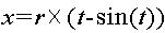
為了將二維平面擺線轉換為三維擺線,若列出代表擺線上各點之切線坡度(Tangential Slope)的微分函數式(Differential Function),其則為利用擺線的速度函數式(Velocity Function),如以下列之[數學式3]所示。 [數學式3]

Figure 02_image005
In order to convert a two-dimensional plane cycloid to a three-dimensional cycloid, if a differential function formula representing the tangential slope of each point on the cycloid line (Tangential Slope) is listed, it is a velocity function formula using a cycloid (Velocity Function) ), as shown in the following [Mathematical Formula 3]. [Mathematical formula 3]
Figure 02_image005

請參考圖7,以X-Y坐標上之原點C1為中心,半徑為r的圓以原點C1為基準,每次旋轉角度t的圓之函數式如以下[數學式4]及[數學式5]所示。 [數學式4]

Figure 02_image007
[數學式5]
Figure 02_image009
Please refer to FIG. 7, a circle with a radius r based on the origin C1 on the XY coordinates is based on the origin C1, and the function formula of the circle at each rotation angle t is as follows [Mathematical Formula 4] and [Mathematical Formula 5 ] As shown. [Mathematical formula 4]
Figure 02_image007
[Mathematical formula 5]
Figure 02_image009

為了利用該速度函數式導出三維擺線函數式,若將該圓的函數式以原點C1為中心每次旋轉角度t,以此所列出的微分函數式之速度函數式為Z軸,將該圓的中心點從Z軸上的C1同時移動到C2,每次移動角度t,則在以C1為中點、以半徑為r的圓為底邊、高度以從C1至C2的距離為高度的圓柱表面上,圓上之任意點P移動的軌跡成為三維擺線,三維擺線的函數式如下列[數學式6]至[數學式8]所示。 [數學式6]

Figure 02_image007
[數學式7]
Figure 02_image009
[數學式8]
Figure 02_image011
In order to use this velocity function to derive a three-dimensional cycloidal function, if the circle's function is rotated at an angle t centered on the origin C1, the speed function of the differential function listed here is the Z axis. The center point of the circle moves from C1 on the Z axis to C2 at the same time, each time the angle t is moved, the circle with C1 as the midpoint and the radius r as the bottom edge, and the height from the distance from C1 to C2 as the height On the surface of the cylinder, the trajectory of any point P on the circle becomes a three-dimensional cycloid. The functional formula of the three-dimensional cycloid is shown in the following [Mathematical Formula 6] to [Mathematical Formula 8]. [Mathematical formula 6]
Figure 02_image007
[Mathematical formula 7]
Figure 02_image009
[Mathematical formula 8]
Figure 02_image011

本發明之該導流機構20之葉片23應用了三維擺線。當繪製在圓柱表面形成的三維擺線時,若使圓半徑r值根據圓錐漸進地變化,則形成在圓錐表面上表現的三維擺線。各該葉片23之平行於該第一漸縮部21之表面的任一截面係各位於一擺線C上。藉此,含塵氣體由該入口通道11進入後,於該多個葉片23上係沿滯留時間最短的路徑移動,進而減少因摩擦力所造成之動能損失。因此,離心分離效果較佳,且可降低動力源(例如鼓風機)將含塵氣體送入該過濾系統1時所需功率。The blade 23 of the flow guiding mechanism 20 of the present invention uses a three-dimensional cycloid. When drawing a three-dimensional cycloid formed on the surface of a cylinder, if the value of the circle radius r is changed gradually according to the cone, a three-dimensional cycloid expressed on the surface of the cone is formed. Any cross section of each blade 23 parallel to the surface of the first tapered portion 21 is located on a cycloid C, respectively. Thereby, after the dust-containing gas enters through the inlet channel 11, it moves along the path with the shortest residence time on the plurality of blades 23, thereby reducing the loss of kinetic energy due to friction. Therefore, the centrifugal separation effect is better, and the power required by the power source (such as a blower) to send the dust-containing gas into the filter system 1 can be reduced.

1‧‧‧過濾系統10‧‧‧殼體11‧‧‧入口通道12‧‧‧出口通道121‧‧‧管件122‧‧‧擋緣123‧‧‧鰭片124‧‧‧貫孔13‧‧‧排塵通道14‧‧‧擴口部20‧‧‧導流機構21‧‧‧第一漸縮部22‧‧‧第二漸縮部221‧‧‧表面延伸23‧‧‧葉片231‧‧‧斜面24‧‧‧支承件25‧‧‧轉折部30‧‧‧間隙L‧‧‧延伸線C‧‧‧擺線1‧‧‧ Filtration system 10‧‧‧ Housing 11‧‧‧ Inlet channel 12‧‧‧ Outlet channel 121‧‧‧Pipe fitting 122‧‧‧Ball flange 123‧‧‧Finnel 124‧‧‧Through hole 13‧‧ ‧Dust discharge channel 14‧‧‧Expansion part 20‧‧‧Diversion mechanism 21‧‧‧First tapered part 22‧‧‧‧Second tapered part 221‧‧‧Surface extension 23‧‧‧Blade 231‧‧ ‧Slope 24‧‧‧Support 25‧‧‧Turning part 30‧‧‧Gap L‧‧‧Extension line C‧‧‧Cycloid

圖1為本發明一較佳實施例之局部剖視立體圖。 圖2為本發明一較佳實施例之局部剖視圖。 圖3為本發明一較佳實施例另一視角之局部剖視圖。 圖4為本發明一較佳實施例之擋緣之立體圖。 圖5為本發明一較佳實施例之導流機構之側視圖。 圖6為二維擺線之示意圖。 圖7為三維擺線之示意圖。FIG. 1 is a partially cutaway perspective view of a preferred embodiment of the present invention. 2 is a partial cross-sectional view of a preferred embodiment of the present invention. 3 is a partial cross-sectional view of another preferred embodiment of the present invention from another perspective. 4 is a perspective view of a retaining edge of a preferred embodiment of the present invention. FIG. 5 is a side view of a deflector mechanism according to a preferred embodiment of the present invention. Fig. 6 is a schematic diagram of a two-dimensional cycloid. 7 is a schematic diagram of a three-dimensional cycloid.

1‧‧‧過濾系統 1‧‧‧ Filter system

10‧‧‧殼體 10‧‧‧Housing

11‧‧‧入口通道 11‧‧‧ Entrance channel

12‧‧‧出口通道 12‧‧‧Exit channel

122‧‧‧擋緣 122‧‧‧Ball

13‧‧‧排塵通道 13‧‧‧ Dust extraction channel

20‧‧‧導流機構 20‧‧‧Diversion mechanism

24‧‧‧支承件 24‧‧‧Support

Claims (14)

一種過濾系統,包括: 一殼體,包括位於同一延伸線上之一入口通道及一出口通道; 一導流機構,包括一朝該入口通道方向漸縮之第一漸縮部、一朝該出口通道方向漸縮之第二漸縮部及多個葉片,該多個葉片相對於該延伸線螺旋地延伸於該第一漸縮部,該多個葉片與該殼體的內壁之間形成一間隙,該間隙小於該葉片相對該第一漸縮部之表面的一高度。A filtering system includes: a housing including an inlet channel and an outlet channel on the same extension line; a flow guide mechanism including a first tapered portion tapering toward the inlet channel and a outlet channel A second tapered portion tapered in direction and a plurality of blades that spirally extend from the first tapered portion relative to the extension line, and a gap is formed between the blades and the inner wall of the casing , The gap is smaller than a height of the blade relative to the surface of the first tapered portion. 如請求項1所述的過濾系統,其中該殼體另包括一橫向於該延伸線延伸之排塵通道,該排塵通道位於該出口通道的徑向外側。The filtration system according to claim 1, wherein the housing further includes a dust discharge channel extending transverse to the extension line, the dust discharge channel being located radially outward of the outlet channel. 如請求項2所述的過濾系統,其中該出口通道包括一連接該殼體之管件及一周設於該管件外之擋緣,沿該排塵通道之一軸向觀之,該擋緣至少部分位於該管件範圍內。The filtration system according to claim 2, wherein the outlet channel includes a pipe connected to the housing and a baffle rim arranged around the pipe, the baffle rim is at least partially viewed along an axial direction of the dust discharge channel Located within the scope of the pipe. 如請求項3所述的過濾系統,其中該擋緣朝該出口通道方向漸擴。The filtration system according to claim 3, wherein the retaining edge gradually expands toward the outlet passage. 如請求項3所述的過濾系統,其中該擋緣設有多個鰭片,該多個鰭片之延伸方向順向於該葉片的螺旋方向。The filtration system according to claim 3, wherein the retaining edge is provided with a plurality of fins, and the extending direction of the plurality of fins is along the spiral direction of the blade. 如請求項5所述的過濾系統,其中該擋緣一體沖壓貫穿形成多個貫孔及該多個鰭片。The filtration system according to claim 5, wherein the retaining flange is integrally punched to form a plurality of through holes and the plurality of fins. 如請求項1所述的過濾系統,其中該殼體另包括一自該入口通道朝該出口通道方向漸擴之擴口部,該多個葉片與該擴口部形成該間隙。The filtration system according to claim 1, wherein the casing further includes a flared portion gradually expanding from the inlet channel toward the outlet channel, and the plurality of blades and the flared portion form the gap. 如請求項7所述的過濾系統,其中該第一漸縮部及該多個葉片部分伸入該入口通道中。The filtration system of claim 7, wherein the first tapered portion and the plurality of blade portions extend into the inlet channel. 如請求項1所述的過濾系統,其中該第二漸縮部之一表面延伸通過該出口通道。The filtration system of claim 1, wherein a surface of the second tapered portion extends through the outlet channel. 如請求項1所述的過濾系統,其中該導流機構係經由至少一支承件連接支承於該出口通道。The filtration system according to claim 1, wherein the flow guiding mechanism is connected and supported by the outlet channel via at least one support member. 如請求項1所述的過濾系統,其中各該葉片之一末端面為一斜面,該斜面順向於該葉片的螺旋方向。The filtration system according to claim 1, wherein one end surface of each of the blades is an inclined surface, and the inclined surface is along the spiral direction of the blade. 如請求項6所述的過濾系統,其中該擋緣朝該出口通道方向漸擴;該殼體另包括一自該入口通道朝該出口通道方向漸擴之擴口部,該多個葉片與該擴口部形成該間隙;該第一漸縮部及該多個葉片部分伸入該入口通道中;該第二漸縮部之一表面延伸通過該出口通道;該導流機構係經由至少一支承件連接支承於該出口通道;該至少一支承件為複數個;該第一漸縮部及該第二漸縮部間設有一轉折部,該至複數支承件連接於該轉折部與該出口通道;該第一漸縮部及該第二漸縮部皆為圓錐體;該第一漸縮部之錐角不大於該第二漸縮部之錐角;該轉折部橫向於該延伸線之一截面與該出口通道之距離不大於該第二漸縮部之錐高的2倍;各該葉片之一末端面為一斜面,該斜面順向於該葉片的螺旋方向。The filtration system according to claim 6, wherein the retaining edge gradually expands toward the outlet channel; the housing further includes a flared portion gradually expanding from the inlet channel toward the outlet channel, the plurality of blades and the The flared portion forms the gap; the first tapered portion and the plurality of blade portions extend into the inlet channel; a surface of the second tapered portion extends through the outlet channel; the flow guiding mechanism is supported by at least one The connecting member is supported by the outlet channel; the at least one supporting member is plural; a turning part is provided between the first tapering part and the second tapering part, and the plurality of supporting parts are connected to the turning part and the outlet channel The first tapered portion and the second tapered portion are both cones; the cone angle of the first tapered portion is not greater than the cone angle of the second tapered portion; the turning portion is transverse to one of the extension lines The distance between the cross-section and the outlet channel is not greater than 2 times the cone height of the second tapered portion; one of the end surfaces of each blade is a slope, and the slope is along the spiral direction of the blade. 如請求項1至12中任一項所述的過濾系統,其中各該葉片具有一擺線輪廓。The filtration system according to any one of claims 1 to 12, wherein each of the blades has a cycloidal profile. 如請求項13所述的過濾系統,其中各該葉片之平行於該第一漸縮部之表面的任一截面係各位於一擺線上。The filtration system according to claim 13, wherein any cross section of each surface of the blade parallel to the surface of the first tapered portion is located on a pendulum line.
TW107119691A 2018-06-07 2018-06-07 Filtration system TWI641414B (en)

Priority Applications (1)

Application Number Priority Date Filing Date Title
TW107119691A TWI641414B (en) 2018-06-07 2018-06-07 Filtration system

Applications Claiming Priority (1)

Application Number Priority Date Filing Date Title
TW107119691A TWI641414B (en) 2018-06-07 2018-06-07 Filtration system

Publications (2)

Publication Number Publication Date
TWI641414B TWI641414B (en) 2018-11-21
TW202000293A true TW202000293A (en) 2020-01-01

Family

ID=65034408

Family Applications (1)

Application Number Title Priority Date Filing Date
TW107119691A TWI641414B (en) 2018-06-07 2018-06-07 Filtration system

Country Status (1)

Country Link
TW (1) TWI641414B (en)

Families Citing this family (2)

* Cited by examiner, † Cited by third party
Publication number Priority date Publication date Assignee Title
TWI676499B (en) * 2019-05-07 2019-11-11 孫正和 Filtration device
CN112295319B (en) * 2019-08-02 2022-07-15 孙正和 Filter device

Family Cites Families (5)

* Cited by examiner, † Cited by third party
Publication number Priority date Publication date Assignee Title
DE102012211245B4 (en) * 2012-06-29 2018-05-17 BSH Hausgeräte GmbH Vacuum cleaner with vortex separator
GB2508034B (en) * 2012-11-20 2015-10-07 Dyson Technology Ltd Cleaning appliance
KR101578785B1 (en) * 2014-05-16 2015-12-18 손동원 Axial flow type dust collector and pre-collecting device therefor
KR102176885B1 (en) * 2015-01-19 2020-11-10 엘지전자 주식회사 Dust collector for vacuum cleaner
CN206221315U (en) * 2016-11-23 2017-06-06 广东威灵电机制造有限公司 Blower fan

Also Published As

Publication number Publication date
TWI641414B (en) 2018-11-21

Similar Documents

Publication Publication Date Title
US6540917B1 (en) Cyclonic inertial fluid cleaning apparatus
US6921424B2 (en) Dust pre-separator for an automobile engine
US10016768B2 (en) Vortex finder for a cyclonic separator
JP4598060B2 (en) Cyclone separator
JP5077370B2 (en) Cyclone separation device and vacuum cleaner
JP6721362B2 (en) Cyclone separator and air supply hood for house ventilation
TW202000293A (en) Filtration system
JP6527962B2 (en) Multistage axial flow cyclone separator
KR20130142804A (en) Swirl filter
CN112295319B (en) Filter device
TW202041267A (en) Filtration device
JP2010075793A (en) Dust collecting device and vacuum cleaner having the same
JP2023539122A (en) Compact disc stack type cyclone separator
US3026787A (en) Induction air distributors
US20180154375A1 (en) Cyclone separator
JP7142250B2 (en) Separator
CN110876873A (en) Filter system
US20200070079A1 (en) Filtration System
JP3336440B2 (en) Low pressure drop cyclone
CN107073486B (en) Cyclonic separating apparatus comprising two cyclonic separators connected by an optimised tube unit
US9861913B2 (en) Centrifugal separator
KR20190051142A (en) Dust collector using axial flow cyclone
TWI704959B (en) Multi-cyclone dust filter
SU1766527A1 (en) Dust collector
JP5734691B2 (en) Cyclone separator