RU95100248A - Alternating current two-phase motor - Google Patents
Alternating current two-phase motorInfo
- Publication number
- RU95100248A RU95100248A RU95100248/07A RU95100248A RU95100248A RU 95100248 A RU95100248 A RU 95100248A RU 95100248/07 A RU95100248/07 A RU 95100248/07A RU 95100248 A RU95100248 A RU 95100248A RU 95100248 A RU95100248 A RU 95100248A
- Authority
- RU
- Russia
- Prior art keywords
- coils
- poles
- yoke
- axis
- pole
- Prior art date
Links
Landscapes
- Iron Core Of Rotating Electric Machines (AREA)
- Windings For Motors And Generators (AREA)
Abstract
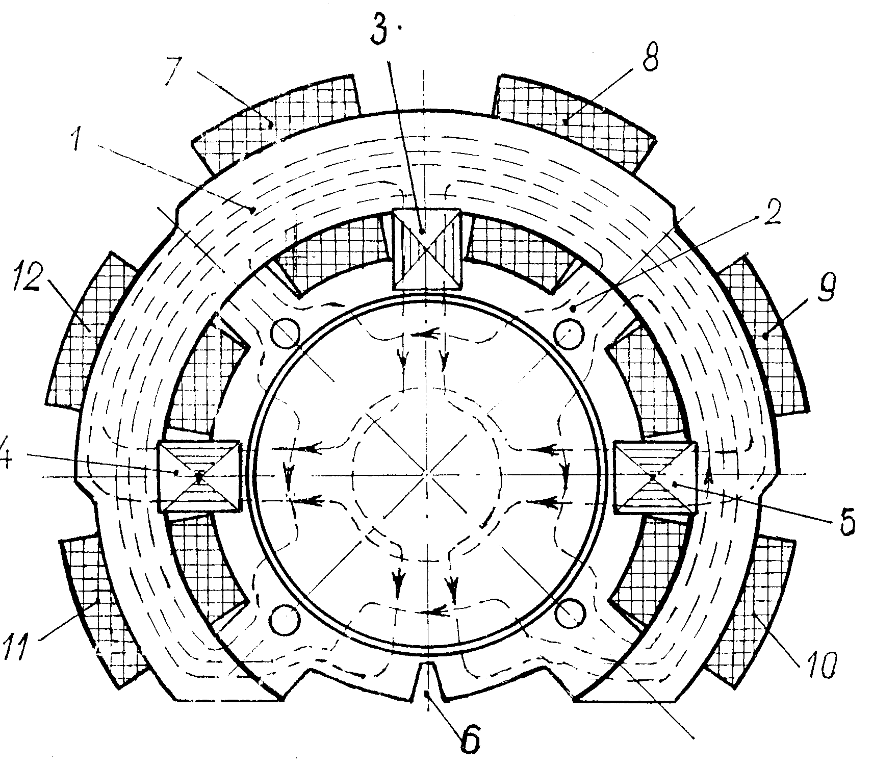
FIELD: production of electric machines, synchronous and asynchronous low-power motors production in particular. SUBSTANCE: aim is to decrease active materials and labour consumption, to improve process in the electric motor production. Proposed design decision allows to adjust form of curve of magnetic field distribution in machine clearance due to choice of structural ratios in stator magnetic circuit and so to improve motor performance. Stator magnetic circuit of proposed motor has ring type opened yoke 1, ring type magnetic holder 2 and three poles 3, 4, 5 built-up of laminations, planes of which are in parallel to radial plane, that goes through the pole axis and motor axis. Yoke 1 and magnetic holder 2 are usually built-up of laminations, axes of which are perpendicular to the machine axis. Poles 3 - 5 are mounted in grooves made on outer surface of cylindrical holder 2. Pole 4 and 5 are located diametrically opposite to each other and pole 3 is located in the middle between them. Holder 2 has slit 6 located diametrically to middle pole 3 and preventing closing of coils 7 and 8 phase flow passing by rotor. On outer surface of holder 2 there are four bulges, radial axes of which are located at angle of 45 deg to poles axes. Ring type open yoke 1 is pressed on holder 2 bulges and poles 3 - 5. Yoke is to be open for the purpose, that lines of field force created by phase of coils 7 and 8 do not close round passing by rotor and that stator windings 7 -12 set in their places before yoke is pressed in. Part of yoke, that is located opposite slit 6 between two adjacent to it bulges, is absent. Stator winding coils 7 - 12 are wound separately on forms and inserted in yoke through space of its absent part before magnetic holder 2 and poles 3 - 5 are pressed in yoke. Coils inner sides are located between bulges of magnetic insert and poles. One phase of winding has two coils 7 and 8 located on both sides of middle pole 3 and another phase of winding has two half-phases, each of which has two coils (9 and 10, 11 and 12) located on both side of each of other poles (4 and 5). Coils of phases are connected to each other in the way, that axis of field of phase composed of coils 7 and 8 coincides with axis of poles 4 and 5 ( lines of the field force shown on drawing have horizontal arrows) and axis of field of phase composed of coils 9, 10, 11, 12 coincides with axis of pole 3 and sleet 6 (arrows of the field force lines are vertical). EFFECT: decreased active materials and labour consumption, improved process.
Claims (1)
Priority Applications (1)
| Application Number | Priority Date | Filing Date | Title |
|---|---|---|---|
| RU95100248A RU2088029C1 (en) | 1995-01-10 | 1995-01-10 | Split-phase ac motor |
Applications Claiming Priority (1)
| Application Number | Priority Date | Filing Date | Title |
|---|---|---|---|
| RU95100248A RU2088029C1 (en) | 1995-01-10 | 1995-01-10 | Split-phase ac motor |
Publications (2)
| Publication Number | Publication Date |
|---|---|
| RU95100248A true RU95100248A (en) | 1996-11-27 |
| RU2088029C1 RU2088029C1 (en) | 1997-08-20 |
Family
ID=20163818
Family Applications (1)
| Application Number | Title | Priority Date | Filing Date |
|---|---|---|---|
| RU95100248A RU2088029C1 (en) | 1995-01-10 | 1995-01-10 | Split-phase ac motor |
Country Status (1)
| Country | Link |
|---|---|
| RU (1) | RU2088029C1 (en) |
Families Citing this family (2)
| Publication number | Priority date | Publication date | Assignee | Title |
|---|---|---|---|---|
| RU2672032C1 (en) * | 2017-11-23 | 2018-11-08 | Владимир Михайлович Стексов | Asynchronous low-current engine with concentrated poles and power supply from electronic controlled source of current special trapezoidal form |
| RU2726627C1 (en) * | 2020-03-16 | 2020-07-15 | Вальдемар Олегович Вагнер | Electric motor |
-
1995
- 1995-01-10 RU RU95100248A patent/RU2088029C1/en active
Also Published As
| Publication number | Publication date |
|---|---|
| RU2088029C1 (en) | 1997-08-20 |
Similar Documents
| Publication | Publication Date | Title |
|---|---|---|
| CA1167897A (en) | Half-pitch capacitor induction motor | |
| US4752707A (en) | Three-phase, one-third pitch motor | |
| US4774428A (en) | Compact three-phase permanent magnet rotary machine having low vibration and high performance | |
| US3978356A (en) | Self-starting synchronous motor with permanent magnet rotor | |
| MX2013005413A (en) | Dipeptide analogs for treating conditions associated with amyloid fibril formation. | |
| US6100620A (en) | High frequency synchronous rotary electrical machine | |
| US4847982A (en) | Method of winding a three-phase, one-third pitch motor | |
| US10673311B2 (en) | Electric motor with low torque ripple | |
| CN114709950A (en) | Motor rotor, motor, compressor and air conditioner | |
| CN109599962A (en) | A kind of double salient-pole electric machine of new split-phase form | |
| US20170271930A1 (en) | Rotor having flux filtering function and synchronous motor comprising same | |
| CN115940559B (en) | Stator offset type doubly salient permanent magnet motor | |
| RU95100248A (en) | Alternating current two-phase motor | |
| US20190312476A1 (en) | Motor | |
| US5739612A (en) | Auxiliary power source | |
| KR100444326B1 (en) | Single phase induction motor and hermetic reciprocal compressor having single phase induction motor | |
| JPH04210758A (en) | Permanent magnet rotor | |
| KR101123676B1 (en) | Synchronous motor having rotor formed magnetic flux guide hole | |
| EP3731388A1 (en) | Single-phase permanent magnet brushless direct-current motor | |
| KR102120361B1 (en) | A rotor having a conductor bar of a different length and a synchronous motor comprising the same | |
| RU2819416C1 (en) | Electric machine (versions) | |
| RU2819416C9 (en) | Electric machine (versions) | |
| WO2018178236A1 (en) | Permanent magnet three phase machine for high speed applications having low vibration and low resistive losses | |
| CN215528713U (en) | Permanent magnet direct current generator | |
| JP2001157427A (en) | Permanent-magnet synchronous motor |