RU83717U1 - PIPE CLEANING TOOL - Google Patents
PIPE CLEANING TOOL Download PDFInfo
- Publication number
- RU83717U1 RU83717U1 RU2009103127/22U RU2009103127U RU83717U1 RU 83717 U1 RU83717 U1 RU 83717U1 RU 2009103127/22 U RU2009103127/22 U RU 2009103127/22U RU 2009103127 U RU2009103127 U RU 2009103127U RU 83717 U1 RU83717 U1 RU 83717U1
- Authority
- RU
- Russia
- Prior art keywords
- wire
- diameter
- layer
- cleaning tool
- pipe cleaning
- Prior art date
Links
Abstract
Инструмент для прочистки труб, содержащий гибкий вал с установленными на нем двумя слоями проволоки, причем один слой проволоки имеет правую навивку, а другой левую, с одной стороны вала жестко установлена ручка для придания ему вращения, отличающийся тем, что диаметр проволоки верхнего слоя больше диаметра проволоки нижнего слоя.A pipe cleaning tool comprising a flexible shaft with two layers of wire mounted on it, one wire layer having a right-hand winding and the other left, a handle for rigid rotation is fixed on one side of the shaft, characterized in that the diameter of the wire of the upper layer is larger than the diameter wire bottom layer.
Description
Полезная модель относится к ручному инструменту для очистки внутренней поверхности труб от засоров, жировых отложений и может быть использована при эксплуатации зданий и сооружений.The utility model relates to a hand tool for cleaning the inner surface of pipes from blockages, fat deposits and can be used in the operation of buildings and structures.
Широко известен ручной инструмент для удаления засоров, который содержит гибкий вал в виде троса с установленной на него ручкой для придания вращения. На конец троса может быть установлены различные насадки для увеличения эффективности очистки (www.stroynet.ru/market_unit20126.htm, см. Приложение 1 к заявке).The manual tool for removing blockages is widely known, which contains a flexible shaft in the form of a cable with a handle mounted on it to impart rotation. At the end of the cable, various nozzles can be installed to increase the cleaning efficiency (www.stroynet.ru/market_unit20126.htm, see Appendix 1 to the application).
Недостатком данной конструкции является не высокая жесткость гибкого вала. Это приводит к перекручиванию троса при сильных засорах и его «срыву», что может привести к травме рук человека. Кроме того, в процессе работы возникает необходимость придания тросу обратного вращения, при этом происходят изменения у сечения троса, что приводит к его преждевременному износу.The disadvantage of this design is the low rigidity of the flexible shaft. This leads to the twisting of the cable with severe blockages and its "breakdown", which can lead to personal injury. In addition, during operation, there is a need to give the cable reverse rotation, while there are changes at the cross section of the cable, which leads to its premature wear.
Наиболее близким техническим решением является инструмент, который содержит гибкий вал с установленным на нем двумя слоями проволоки, причем один слой проволоки имеет правую навивку, а один левую, с одной стороны вала, жестко установлена ручка для придания ему вращения ( . См. Приложение 2 к заявке) - прототип.The closest technical solution is a tool that contains a flexible shaft with two layers of wire installed on it, with one layer of wire having a right-hand winding and one left, on one side of the shaft, a handle is rigidly mounted to give it rotation (see Appendix 2 to application) - prototype.
Недостатком данного технического решения является то, что при больших нагрузках, перекручивании, происходит проникновение проволоки верхнего слоя между слоев проволоки нижнего слоя, что приводит к изменению диаметра гибкого вала и его преждевременному износу.The disadvantage of this technical solution is that under heavy loads, twisting, the penetration of the wire of the upper layer between the layers of the wire of the lower layer, which leads to a change in the diameter of the flexible shaft and its premature wear.
Технической задачей заявляемой полезной модели является повышение жесткости гибкого вала инструмента и его долговечности.The technical task of the claimed utility model is to increase the rigidity of the flexible shaft of the tool and its durability.
Техническая задача достигается тем, что известное устройство содержит гибкий вал с установленным на нем двумя слоями проволоки, причем один слой проволоки имеет правую навивку, а один левую, с одной стороны вала, жестко установлена ручка для придания ему вращения, причем диаметр проволоки верхнего слоя больше диаметра проволоки нижнего слоя.The technical problem is achieved by the fact that the known device contains a flexible shaft with two layers of wire installed on it, with one layer of wire having a right-hand winding and one left, one side of the shaft, with a handle rigidly mounted to make it rotate, and the wire diameter of the upper layer is larger wire diameter of the lower layer.
Сравнение заявляемой полезной модели с прототипом показывает, что она отличается от прототипа следующими признаками:Comparison of the claimed utility model with the prototype shows that it differs from the prototype in the following features:
- диаметр проволоки верхнего слоя больше диаметра проволоки нижнего слоя.- the diameter of the wire of the upper layer is larger than the diameter of the wire of the lower layer.
Поэтому можно предположить, что полезная модель соответствует критерию «новизна».Therefore, we can assume that the utility model meets the criterion of "novelty."
Полезная модель может быть изготовлена на стандартном оборудовании с использованием известных технологических процессов, поэтому она соответствует критерию «промышленная применимость».The utility model can be manufactured on standard equipment using well-known technological processes, therefore it meets the criterion of "industrial applicability".
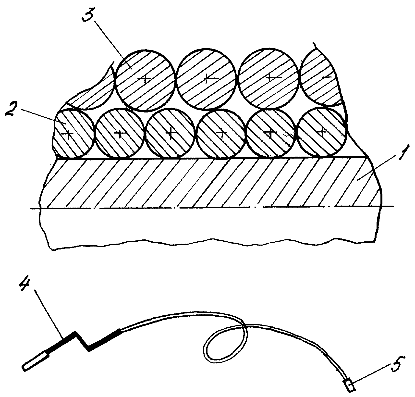
На рисунке схематично показан инструмент для прочистки труб, который был изготовлен для промышленных испытаний.The figure schematically shows a pipe cleaning tool that was manufactured for industrial testing.
Инструмент содержит трос 1, на который установлено два слоя проволоки 2 и 3. Слои проволоки имеют разную навивку. Слой 2 имеет левую навивку, а слой 3 - правую. С одной стороны на вал установлена ручка 4 для обеспечения возможности его вращения, а с другой стороны витки проволоки имеют заделку 5. Для того чтобы при работе, особенно при перекручивании, витки верхнего слоя не проникали между витков нижнего слоя конструкция предусматривает, что диаметр проволоки витков верхнего слоя больше диаметра витков проволоки нижнего слоя. Например, были изготовлены инструменты, где диаметр проволоки нижнего слоя 0,8 мм, а диаметр проволоки верхнего слоя - 1,2 мм, и соответственно второго инструмента 1,2-1,5 мм. Испытания устройств показали, что за счет большего диаметра проволоки верхнего слоя конструкция имеет большую жесткость, поэтому при сильных засорах позволяет, уменьшит вероятность «срывов». Вследствие The tool contains a cable 1, on which two layers of wire 2 and 3 are installed. The layers of wire have different windings. Layer 2 has a left winding, and layer 3 has a right. On the one hand, a handle 4 is mounted on the shaft to allow rotation, and on the other hand, the coils of wire are sealed 5. In order to ensure that the coils of the upper layer do not penetrate between the coils of the lower layer during operation, the design assumes that the diameter of the wire is the upper layer is larger than the diameter of the turns of wire of the lower layer. For example, tools were made where the diameter of the wire of the lower layer is 0.8 mm, and the diameter of the wire of the upper layer is 1.2 mm, and accordingly the second tool is 1.2-1.5 mm. Tests of the devices showed that due to the larger diameter of the wire of the upper layer, the structure has greater rigidity, therefore, with strong blockages it allows, reduces the likelihood of "breakdowns". Due to
того что, при работе уменьшена вероятность проникновения витков проволоки верхнего слоя между витков проволоки нижнего слоя, конструкция не позволяет при усилиях, которые возникают при больших засорах, значительно изменять диаметр троса, что увеличивает работоспособность и долговечность заявляемого устройства.the fact that, during operation, the probability of penetration of the turns of wire of the upper layer between the turns of wire of the lower layer is reduced, the design does not allow the efforts that occur with large blockages to significantly change the diameter of the cable, which increases the efficiency and durability of the claimed device.
Claims (1)
Priority Applications (1)
| Application Number | Priority Date | Filing Date | Title |
|---|---|---|---|
| RU2009103127/22U RU83717U1 (en) | 2009-01-30 | 2009-01-30 | PIPE CLEANING TOOL |
Applications Claiming Priority (1)
| Application Number | Priority Date | Filing Date | Title |
|---|---|---|---|
| RU2009103127/22U RU83717U1 (en) | 2009-01-30 | 2009-01-30 | PIPE CLEANING TOOL |
Publications (1)
| Publication Number | Publication Date |
|---|---|
| RU83717U1 true RU83717U1 (en) | 2009-06-20 |
Family
ID=41026182
Family Applications (1)
| Application Number | Title | Priority Date | Filing Date |
|---|---|---|---|
| RU2009103127/22U RU83717U1 (en) | 2009-01-30 | 2009-01-30 | PIPE CLEANING TOOL |
Country Status (1)
| Country | Link |
|---|---|
| RU (1) | RU83717U1 (en) |
Cited By (5)
| Publication number | Priority date | Publication date | Assignee | Title |
|---|---|---|---|---|
| USD764176S1 (en) | 2014-07-31 | 2016-08-23 | Colgate-Palmolive Company | Oral care implement |
| USD764177S1 (en) | 2014-07-31 | 2016-08-23 | Colgate-Palmolive Company | Oral care implement |
| USD961269S1 (en) | 2020-07-31 | 2022-08-23 | Colgate-Palmolive Company | Oral care implement |
| US11622618B2 (en) | 2018-12-13 | 2023-04-11 | Colgate-Palmolive Company | Oral care implement |
| USD1023582S1 (en) | 2022-01-28 | 2024-04-23 | Colgate-Palmolive Company | Toothbrush |
-
2009
- 2009-01-30 RU RU2009103127/22U patent/RU83717U1/en not_active IP Right Cessation
Cited By (10)
| Publication number | Priority date | Publication date | Assignee | Title |
|---|---|---|---|---|
| USD764176S1 (en) | 2014-07-31 | 2016-08-23 | Colgate-Palmolive Company | Oral care implement |
| USD764177S1 (en) | 2014-07-31 | 2016-08-23 | Colgate-Palmolive Company | Oral care implement |
| USD813550S1 (en) | 2014-07-31 | 2018-03-27 | Colgate-Palmolive Company | Oral care implement |
| USD814796S1 (en) | 2014-07-31 | 2018-04-10 | Colgate-Palmolive Company | Oral care implement |
| USD860653S1 (en) | 2014-07-31 | 2019-09-24 | Colgate-Palmolive Company | Toothbrush |
| USD886460S1 (en) | 2014-07-31 | 2020-06-09 | Colgate-Palmolive Company | Toothbrush |
| US11622618B2 (en) | 2018-12-13 | 2023-04-11 | Colgate-Palmolive Company | Oral care implement |
| USD961269S1 (en) | 2020-07-31 | 2022-08-23 | Colgate-Palmolive Company | Oral care implement |
| USD1023582S1 (en) | 2022-01-28 | 2024-04-23 | Colgate-Palmolive Company | Toothbrush |
| USD1024571S1 (en) | 2022-06-17 | 2024-04-30 | Colgate-Palmolive Company | Oral care implement |
Similar Documents
| Publication | Publication Date | Title |
|---|---|---|
| RU83717U1 (en) | PIPE CLEANING TOOL | |
| EP2623274A3 (en) | Magnetic end effector and device for guiding and positioning the same | |
| EP2400637A3 (en) | Electric motor | |
| EP2138028A3 (en) | Beating apparatus, particularly for beating olives and the like | |
| EP2078490A3 (en) | Electrical device with an improved cable coiling system and method for operating such an electrical device | |
| EP2368476A3 (en) | A cleaning implement comprising hybrid foam | |
| EP2441996A3 (en) | Bellows and flexible line element with same | |
| CN204338319U (en) | Iron filings cleaning tool | |
| EP3012036A3 (en) | Device for cleaning of pipes | |
| EP2891834A3 (en) | Harmonic drive gearing | |
| CN205042832U (en) | Sponge iron iron pipe inner wall descaling machine | |
| EP2757219A3 (en) | Drive device for a sliding door | |
| EP2818771A3 (en) | A brush seal | |
| JP2008206798A5 (en) | ||
| EP2340755A3 (en) | Telescopic device for a vacuum cleaner | |
| DE112015005882T5 (en) | For removing hair suitable pipe cleaning device | |
| EP1967117A3 (en) | Cleaning tool and cleaning element | |
| EP2040317A3 (en) | Solution processed organic device having an improved electrode | |
| MX2016011883A (en) | Wire. | |
| CN204232132U (en) | A kind of manual tuna fishes machine | |
| CN204448485U (en) | One probes into absorption type pipeline spring hammer | |
| CN204221571U (en) | A kind of oppositely rust remover | |
| EP2594180A3 (en) | Cleaning device, in particular vacuum cleaner | |
| CN102709843B (en) | Remove the special cleaner of high-altitude ground wire hanger | |
| CN205432622U (en) | Be used for folding circular arc of small -bore erlenmeyer flask to pitch clean cleaning brush more |
Legal Events
| Date | Code | Title | Description |
|---|---|---|---|
| MM1K | Utility model has become invalid (non-payment of fees) |
Effective date: 20170131 |