RU69964U1 - PROTECTIVE CASING - Google Patents
PROTECTIVE CASING Download PDFInfo
- Publication number
- RU69964U1 RU69964U1 RU2007127808/22U RU2007127808U RU69964U1 RU 69964 U1 RU69964 U1 RU 69964U1 RU 2007127808/22 U RU2007127808/22 U RU 2007127808/22U RU 2007127808 U RU2007127808 U RU 2007127808U RU 69964 U1 RU69964 U1 RU 69964U1
- Authority
- RU
- Russia
- Prior art keywords
- casing
- platform
- engine
- possibility
- protective
- Prior art date
Links
- 230000001681 protective effect Effects 0.000 title claims abstract description 9
- 238000004519 manufacturing process Methods 0.000 abstract description 8
- 239000002184 metal Substances 0.000 abstract description 8
- 230000009993 protective function Effects 0.000 abstract description 3
- 238000010276 construction Methods 0.000 abstract description 2
- 238000005452 bending Methods 0.000 description 2
- 230000005540 biological transmission Effects 0.000 description 2
- 238000003466 welding Methods 0.000 description 2
- 102220543942 Protocadherin-10_F16P_mutation Human genes 0.000 description 1
- 229910000831 Steel Inorganic materials 0.000 description 1
- 230000006870 function Effects 0.000 description 1
- 239000010959 steel Substances 0.000 description 1
- 239000003351 stiffener Substances 0.000 description 1
Landscapes
- Vehicle Step Arrangements And Article Storage (AREA)
Abstract
Полезная модель может быть использована в промышленности, в сельском хозяйстве, в строительстве и в других областях для защиты стационарных устройств от аварийных воздействий, в частности, для ограждения ременной передачи двигателя, установленного на платформе виброрейки, от попадания в нее посторонних предметов. Технический результат заявленного устройства заключается в снижении себестоимости продукции при сохранении качественных показателей защитных функций кожуха в целом за счет уменьшения металлоемкости и трудоемкости изготовления. Защитный кожух 1 выполнен из верхней 2 и нижней 3 частей с возможностью прикрепления верхней части к двигателю 13, установленному на платформе 14, а нижней части 3 - к платформе 14. Верхняя часть 2 кожуха выполнена с возможностью охвата его нижней части 3. 1 доп. пункт формулы, 6 чертежей.The utility model can be used in industry, in agriculture, in construction, and in other fields to protect stationary devices from accidental impacts, in particular, to protect the belt drive of the engine mounted on the platform of the vibration rail from the ingress of foreign objects into it. The technical result of the claimed device is to reduce the cost of production while maintaining the quality indicators of the protective functions of the casing as a whole by reducing the metal consumption and the complexity of manufacturing. The protective casing 1 is made of upper 2 and lower 3 parts with the possibility of attaching the upper part to the engine 13 mounted on the platform 14, and the lower part 3 to the platform 14. The upper part 2 of the casing is made with the possibility of covering its lower part 3. 1 add. claim, 6 drawings.
Description
Полезная модель может быть использована в промышленности, в сельском хозяйстве, в строительстве и в других отраслях для защиты стационарных устройств от аварийных воздействий, в частности, для ограждения ременной передачи двигателя, установленного на платформе виброрейки, от попадания в нее посторонних предметов.The utility model can be used in industry, in agriculture, in construction, and in other industries to protect stationary devices from accidental impacts, in particular, to protect the belt drive of an engine mounted on a platform of a vibrorail from getting foreign objects into it.
Известен защитный кожух моноблочного типа, содержащий днище и боковую стенку, при этом днище выполнено выпуклым с трапециевидными ребрами жесткости и имеет крепежные проушины (см. патент на полезную модель №46833, F16P 1/02, 2005 г.).Known protective casing of a monoblock type containing a bottom and a side wall, while the bottom is convex with trapezoidal stiffeners and has fixing eyes (see patent for utility model No. 46833, F16P 1/02, 2005).
Недостатком этого устройства является большая металлоемкость и значительная трудоемкость изготовления.The disadvantage of this device is the large metal consumption and the significant complexity of manufacturing.
Известен также защитный кожух моноблочного типа, содержащий днище и боковые стенки, ограждающие ременную передачу двигателя (см. авторское свидетельство №1795199, F16H 7/02, 1990).Also known is a protective casing of a monoblock type containing a bottom and side walls enclosing a belt drive of an engine (see copyright certificate No. 1795199, F16H 7/02, 1990).
Это устройство имеет те же недостатки, что и предыдущее.This device has the same disadvantages as the previous one.
Технический результат заявленного устройства заключается в снижении себестоимости продукции при сохранении качественных показателей защитных The technical result of the claimed device is to reduce the cost of production while maintaining the quality indicators of protective
функций кожуха в целом за счет уменьшения металлоемкости и трудоемкости изготовления.the functions of the casing as a whole by reducing the metal consumption and the complexity of manufacturing.
Указанный технический результат достигается за счет того, что защитный кожух, преимущественно для защиты ременной передачи установленного на платформе двигателя, содержащий днище и боковые стенки, выполнен из верхней и нижней частей с возможностью прикрепления верхней части к двигателю, а нижней части - к платформе.The specified technical result is achieved due to the fact that the protective casing, mainly for protecting the belt drive mounted on the platform of the engine, containing the bottom and side walls, is made of upper and lower parts with the possibility of attaching the upper part to the engine, and the lower part to the platform.
При этом верхняя часть кожуха выполнена с возможностью охвата его нижней части.While the upper part of the casing is made with the possibility of covering its lower part.
Заявленная полезная модель поясняется чертежами, гдеThe claimed utility model is illustrated by drawings, where
на фиг.1 изображен кожух, общий вид;figure 1 shows the casing, a General view;
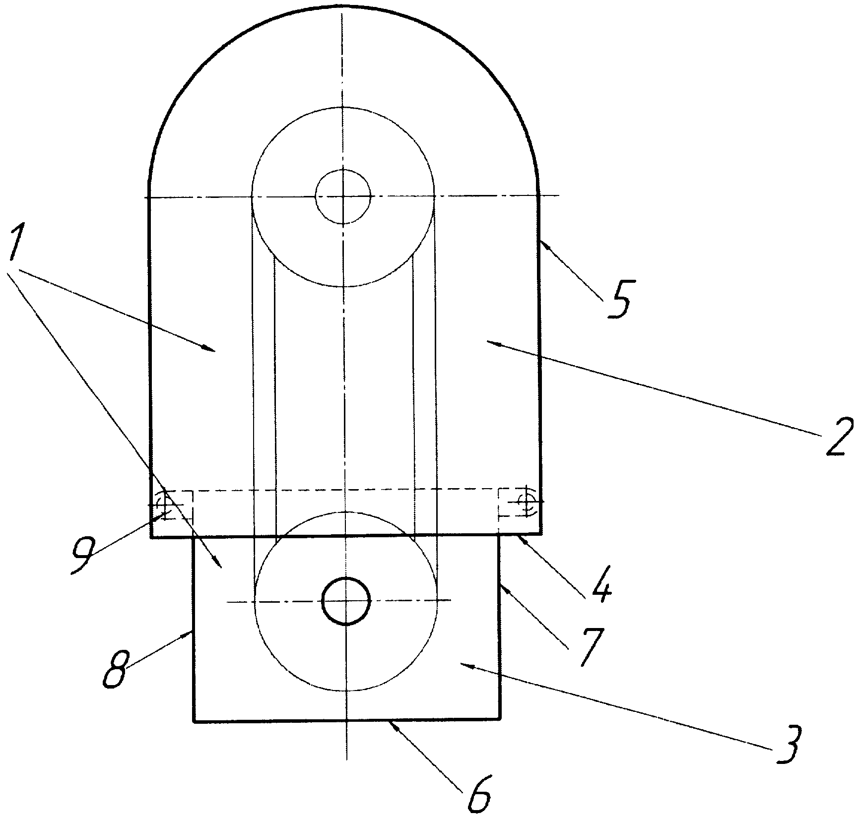
на фиг.2 - верхняя часть кожуха;figure 2 - the upper part of the casing;
на фиг.3 - боковая стенка верхней части:figure 3 - side wall of the upper part:
на фиг.4 - нижняя часть кожуха;figure 4 - the lower part of the casing;
на фиг.5 - то же, в момент изготовления до изгибания;figure 5 is the same at the time of manufacture before bending;
на фиг.6 - кожух в рабочем положении, защищающий ременную передачу двигателя, установленного на платформе виброрейки.figure 6 - casing in the working position, protecting the belt drive of the engine mounted on the platform of the vibrorails.
Защитный кожух 1 состоит из двух частей: верхней части 2 и нижней части 3, выполненных из листового металла. Верхняя часть 2 кожуха 1 имеет днище 4 и боковую стенку 5, обеспечивающую защиту сверху и с боковых сторон. Нижняя часть 3 кожуха 1 имеет днище 6 и боковые стенки 7 и 8, обеспечивающие защиту снизу и с боковых сторон. Стенка 7 выполнена с The protective casing 1 consists of two parts: the upper part 2 and the lower part 3, made of sheet metal. The upper part 2 of the casing 1 has a bottom 4 and a side wall 5, which provides protection from above and from the sides. The lower part 3 of the casing 1 has a bottom 6 and side walls 7 and 8, providing protection from below and from the sides. Wall 7 is made with
отбортовкой 9. Обращенные друг к другу части 2 и 3 кожуха 1 не имеют боковых стенок (ограждений). Верхняя часть 2 кожуха выполнена с возможностью охвата нижней его части 3. На стенке 5 верхней части 2 кожуха 1 выполнены отверстия 10 под крепеж, например болты (на чертежах не показаны). На нижней части 3 кожуха 1 выполнены проушины 11 с отверстиями 12 под крепеж. Толщина листа верхней части 2 кожуха 1 меньше толщины листа нижней части 3 кожуха 1.flanging 9. The parts 2 and 3 of the casing 1 facing each other do not have side walls (fences). The upper part 2 of the casing is made with the possibility of covering its lower part 3. On the wall 5 of the upper part 2 of the casing 1 holes 10 are made for fasteners, for example bolts (not shown in the drawings). On the lower part 3 of the casing 1, eyes 11 are made with holes 12 for fasteners. The thickness of the sheet of the upper part 2 of the casing 1 is less than the thickness of the sheet of the lower part 3 of the casing 1.
Устройство изготавливают и используют следующим образом. Работа описана на примере защиты ременной передачи двигателя, установленного на платформе виброрейки.The device is manufactured and used as follows. The work is described by the example of protection of a belt drive of an engine mounted on a vibrorail platform.
Верхнюю часть 2 кожуха 1 изготавливают из двух частей: днища 4 и стенки 5, которые вырезают из листового металла, например из стали, и прикрепляют друг к другу сваркой. Часть 2 крепится к двигателю 13 через отверстия 10, например, болтами.The upper part 2 of the casing 1 is made of two parts: the bottom 4 and the wall 5, which are cut out of sheet metal, for example steel, and attached to each other by welding. Part 2 is attached to the engine 13 through holes 10, for example, with bolts.
Затем вырезают нижнюю часть 3 кожуха 1, отгибают боковые и нижнюю стенки 7 и 8 и отбортовку 9. Размещают часть 3 кожуха внутри части 2. Нижнюю стенку 8 вставляют в прорезь (не показано) платформы 13 виброрейки, дополнительно фиксируют относительно платформы 14 отбортовкой 9, и через отверстия 12 проушин 11 прикрепляют к корпусу двигателя 13 болтами (не показано). Ременная передача двигателя при этом защищена со всех сторон от попадания посторонних предметов. После установки и закрепления частей кожуха, запускают двигатель виброрейки.Then cut out the lower part 3 of the casing 1, unbend the side and lower walls 7 and 8 and flanging 9. Place part 3 of the casing inside part 2. The lower wall 8 is inserted into the slot (not shown) of the platform 13 vibrorails, additionally fixed relative to the platform 14 by flanging 9, and through the holes 12 of the eyes 11 are attached to the motor housing 13 with bolts (not shown). The engine belt transmission is protected on all sides from foreign objects. After installing and securing the parts of the casing, the engine starts vibrorails.
Верхняя часть 2 имеет большие габариты, чем нижняя, и выполнена из более тонкого листа, что позволило снизить металлоемкость кожуха в целом. Стенка 5 и днище 4 части 2 кожуха 1 выполняют защитную функцию, предотвращая попадание посторонних предметов в ременную передачу. Толщина листа металла нижней части 3 кожуха оптимально подобрана экспериментальным путем. Стенки 7, 8 и днище 6 служат защитой от попадания посторонних предметов в зону ременной передачи, а стенка 7 выполняет не только защитную функцию, но и является элементом крепления части 3 к платформе 14 виброрейки. Части кожуха быстро и легко изготавливают резанием с последующей сваркой (верхняя часть) и изгибанием (нижняя часть), что снижает трудоемкость изготовления. Снижение металлоемкости и трудоемкости позволяет снизить себестоимость продукции при сохранении качественных показателей.The upper part 2 has larger dimensions than the lower one and is made of a thinner sheet, which allowed to reduce the metal consumption of the casing as a whole. The wall 5 and the bottom 4 of the part 2 of the casing 1 perform a protective function, preventing the ingress of foreign objects into the belt drive. The thickness of the metal sheet of the lower part 3 of the casing is optimally selected experimentally. Walls 7, 8 and bottom 6 serve as protection against foreign objects getting into the belt transmission zone, and wall 7 performs not only a protective function, but also is an element of fastening of part 3 to the platform 14 of the vibrorail. Parts of the casing are quickly and easily made by cutting, followed by welding (upper part) and bending (lower part), which reduces the complexity of manufacturing. Reducing metal consumption and labor intensity allows to reduce the cost of production while maintaining quality indicators.
Claims (2)
Priority Applications (1)
| Application Number | Priority Date | Filing Date | Title |
|---|---|---|---|
| RU2007127808/22U RU69964U1 (en) | 2007-07-20 | 2007-07-20 | PROTECTIVE CASING |
Applications Claiming Priority (1)
| Application Number | Priority Date | Filing Date | Title |
|---|---|---|---|
| RU2007127808/22U RU69964U1 (en) | 2007-07-20 | 2007-07-20 | PROTECTIVE CASING |
Publications (1)
| Publication Number | Publication Date |
|---|---|
| RU69964U1 true RU69964U1 (en) | 2008-01-10 |
Family
ID=39020623
Family Applications (1)
| Application Number | Title | Priority Date | Filing Date |
|---|---|---|---|
| RU2007127808/22U RU69964U1 (en) | 2007-07-20 | 2007-07-20 | PROTECTIVE CASING |
Country Status (1)
| Country | Link |
|---|---|
| RU (1) | RU69964U1 (en) |
-
2007
- 2007-07-20 RU RU2007127808/22U patent/RU69964U1/en not_active IP Right Cessation
Similar Documents
| Publication | Publication Date | Title |
|---|---|---|
| RU2479420C2 (en) | Motorised saw | |
| ATE370342T1 (en) | INTEGRATED FASTENING SYSTEM | |
| WO2009054184A1 (en) | Construction machine | |
| RU2015105252A (en) | LIFTING CHAIN BLOCK | |
| US4908008A (en) | Safety guard | |
| RU69964U1 (en) | PROTECTIVE CASING | |
| JP2009068178A (en) | Pent-roof | |
| PH12020550150A1 (en) | Metal wall material and wall construction method using same | |
| CN100445533C (en) | Engine sensor mounting member | |
| JP7030590B2 (en) | Protective cover for rotating equipment and rotating equipment equipped with it | |
| EP1959138A1 (en) | Terminal cover and terminal protection structure | |
| CN202032066U (en) | Micro-cultivator and gearbox | |
| US10393253B2 (en) | Transmission case | |
| JP5723251B2 (en) | Anti-theft device for grating | |
| ATE315135T1 (en) | LID BUCKET SHAFT COVER AND SHAFT COVER | |
| KR20170044406A (en) | Anticorrosive gasket for cylinder head | |
| KR20220001910U (en) | Safety cover of the rotor | |
| JP5453478B2 (en) | Grating | |
| DE602006004598D1 (en) | METHOD FOR CONTROLLING MOBILE PRISM ELEMENTS FOR RECLAMATE TELES | |
| CN215170419U (en) | Engine and vehicle with same | |
| JPH0238798A (en) | Protective structure for vehicular harness, tube, or the like | |
| JP2013174113A (en) | Roof panel connection structure | |
| CN203768976U (en) | Rotary frames in construction machinery | |
| JP4961438B2 (en) | Exterior structure | |
| JP6734622B2 (en) | Side beam mounting bracket for guard fence |
Legal Events
| Date | Code | Title | Description |
|---|---|---|---|
| MM1K | Utility model has become invalid (non-payment of fees) |
Effective date: 20090721 |