RU55152U1 - ELECTRIC CONDUCTIVITY SENSOR - Google Patents
ELECTRIC CONDUCTIVITY SENSOR Download PDFInfo
- Publication number
- RU55152U1 RU55152U1 RU2006103382/22U RU2006103382U RU55152U1 RU 55152 U1 RU55152 U1 RU 55152U1 RU 2006103382/22 U RU2006103382/22 U RU 2006103382/22U RU 2006103382 U RU2006103382 U RU 2006103382U RU 55152 U1 RU55152 U1 RU 55152U1
- Authority
- RU
- Russia
- Prior art keywords
- sensor
- electrodes
- conductivity
- housing
- conductivity sensor
- Prior art date
Links
- 239000012530 fluid Substances 0.000 claims abstract description 15
- 239000007788 liquid Substances 0.000 claims abstract description 9
- 238000013461 design Methods 0.000 abstract description 9
- 238000005259 measurement Methods 0.000 abstract description 6
- 238000004891 communication Methods 0.000 abstract description 4
- 238000011160 research Methods 0.000 abstract description 4
- 238000011010 flushing procedure Methods 0.000 abstract description 3
- 229910001220 stainless steel Inorganic materials 0.000 description 5
- 239000010935 stainless steel Substances 0.000 description 5
- 230000035945 sensitivity Effects 0.000 description 3
- 239000000243 solution Substances 0.000 description 3
- 239000002184 metal Substances 0.000 description 2
- 238000000034 method Methods 0.000 description 2
- 238000004804 winding Methods 0.000 description 2
- 150000001875 compounds Chemical class 0.000 description 1
- 238000012937 correction Methods 0.000 description 1
- 238000010586 diagram Methods 0.000 description 1
- 238000005553 drilling Methods 0.000 description 1
- 230000005672 electromagnetic field Effects 0.000 description 1
- 230000005284 excitation Effects 0.000 description 1
- 229920002313 fluoropolymer Polymers 0.000 description 1
- 230000006698 induction Effects 0.000 description 1
- 230000001939 inductive effect Effects 0.000 description 1
- 239000000463 material Substances 0.000 description 1
- 230000001681 protective effect Effects 0.000 description 1
- 239000000565 sealant Substances 0.000 description 1
- 238000007789 sealing Methods 0.000 description 1
- 239000012085 test solution Substances 0.000 description 1
- 238000012360 testing method Methods 0.000 description 1
- 229910000859 α-Fe Inorganic materials 0.000 description 1
Landscapes
- Investigating Or Analyzing Materials By The Use Of Electric Means (AREA)
Abstract
Полезная модель относится к области геофизических исследований скважин и предназначена для измерения электрической проводимости промывочной жидкости. Задачей полезной модели является упрощение конструкции датчика, снижение его себестоимости, повышение стабильности и достоверности результатов измерений. Датчик электропроводности содержит измерительный преобразователь, выполненный в виде двух тороидальных трансформаторов с общим витком связи. Измерительный преобразователь размещен в одном корпусе с блоком электроники и соединен с электродами, замыкающими жидкостной виток электрической связи. Электроды установлены на изолирующей вставке, размещенной на конце соединительной трубки, и погружены в контролируемую жидкость. На изолирующей вставке установлен также чувствительный элемент датчика температуры. 1 з.п.ф., 1 ил.The utility model relates to the field of geophysical research of wells and is intended to measure the electrical conductivity of the flushing fluid. The objective of the utility model is to simplify the design of the sensor, reduce its cost, increase the stability and reliability of the measurement results. The conductivity sensor contains a measuring transducer made in the form of two toroidal transformers with a common communication loop. The measuring transducer is located in one housing with an electronics unit and is connected to electrodes that close the liquid coil of electrical communication. The electrodes are mounted on an insulating insert located at the end of the connecting tube and are immersed in a controlled fluid. A temperature sensor element is also installed on the insulating insert. 1 C.p.F., 1 ill.
Description
Полезная модель относится к области геофизических исследований скважин и предназначена для измерения электрической проводимости промывочной жидкости.The utility model relates to the field of geophysical research of wells and is intended to measure the electrical conductivity of the flushing fluid.
Известен датчик электропроводности ДЭИ-329-02 для непрерывного измерения удельной электропроводности промывочной жидкости на входе в скважину и на выходе из нее. Конструктивно устройство представляет собой штангу, к нижнему концу которой прикреплен первичный преобразователь погружного типа в защитном кожухе, залитом компаундом. Действие устройства основано на измерении индукционным методом электропроводности жидкостного витка, охватывающего два тороидальных трансформатора. Жидкостной виток создается исследуемым раствором, находящимся как во внутренней полости, так и во внешнем объеме, охватывающем датчик (Буклет ОАО НПП «ГЕРС» «Станция геолого-технологических исследований нефтегазовых скважин «СИРИУС», Тверь, 2002, стр.21).The known conductivity sensor DEI-329-02 for continuous measurement of the conductivity of the flushing fluid at the inlet and outlet of the well. Structurally, the device is a rod, to the lower end of which a primary transducer of a submersible type is attached in a protective casing filled with a compound. The operation of the device is based on the measurement of the conductivity of a liquid coil by induction method, covering two toroidal transformers. A liquid loop is created by the test solution located both in the internal cavity and in the external volume that encompasses the sensor (Booklet of OAO NPP GERS Station for Geological and Technological Research of Oil and Gas Wells SIRIUS, Tver, 2002, p.21).
Недостатком устройства является зависимость показаний датчика от температуры раствора. Кроме того, постоянное нахождение первичного преобразователя в агрессивной среде предъявляет высокие требования к его герметичности. На показания датчика влияют электромагнитные поля, наводящие ЭДС в проводах, размещенных в штанге и соединяющих катушки индуктивности с источником питания и блоком электроники.The disadvantage of this device is the dependence of the sensor on the temperature of the solution. In addition, the constant presence of the primary transducer in an aggressive environment places high demands on its tightness. The sensor readings are affected by electromagnetic fields that induce the EMF in the wires located in the rod and connect the inductance coils to the power source and the electronics.
Известен датчик электропроводности производства ОАО НПФ «Геофизика», принятый за прототип (Ахметин P.M., Лугуманов М.Г. «Высокочувствительный датчик электропроводности бурового раствора», www.npf-geofizika.ru). Датчик преобразует удельную электропроводность раствора в электрический сигнал и состоит из двух частей: индуктивно-трансформаторного измерительного преобразователя и блока электроники.The known conductivity sensor manufactured by JSC NPF Geophysics, adopted as a prototype (Akhmetin P.M., Lugumanov MG "Highly sensitive drilling fluid conductivity sensor", www.npf-geofizika.ru). The sensor converts the conductivity of the solution into an electrical signal and consists of two parts: an inductive transformer measuring transducer and an electronics unit.
Измерительный преобразователь погружен в исследуемую жидкость и представляет собой систему двух соосно расположенных тороидальных трансформаторов, помещенных в цилиндрический корпус из нержавеющей стали и залитых герметиком. Корпус герметично закрыт фторопластовой крышкой, позволяющей сформировать жидкостной виток электрической связи между двумя электродами, одним из которых является корпус измерительного преобразователя, а другим металлическая трубка, внутри которой проходят провода, соединяющие измерительный преобразователь с блоком электроники. Блок электроники размещен в герметичном металлическом корпусе с коммутационным разъемом.The measuring transducer is immersed in the test liquid and is a system of two coaxially arranged toroidal transformers placed in a cylindrical stainless steel casing and filled with sealant. The housing is hermetically sealed with a fluoroplastic cover, which allows to form a liquid coil of electrical connection between two electrodes, one of which is the housing of the measuring transducer, and the other a metal tube, inside of which there are wires connecting the measuring transducer to the electronics. The electronics unit is housed in a sealed metal housing with a switching connector.
Данной конструкции присущи те же недостатки, что и рассмотренной выше в отношении требований к герметичности корпуса измерительного преобразователя, находящегося в жидкости. Изготовление корпуса датчика в виде стакана из нержавеющей стали - очень трудоемкий процесс, при этом большая часть дорогостоящего материала уходит в отходы. Для повышения чувствительности датчика в его конструкции используются катушки большого сечения, которые не обладают достаточной термостабильностью. Кроме того, электропроводность жидкости также зависит от температуры, а известная конструкция не содержит средств для ее контроля и соответствующей коррекции результатов замера электропроводности. Возникает необходимость в дополнительном использовании еще одного датчика - датчика температуры. Замер температуры на некотором расстоянии от датчика электропроводности может привести к искажению результатов исследования.This design has the same disadvantages as discussed above with respect to the requirements for tightness of the housing of the measuring transducer located in the liquid. Making a sensor case in the form of a stainless steel cup is a very time-consuming process, with most of the expensive material being wasted. To increase the sensitivity of the sensor in its design, coils of large cross section are used, which do not have sufficient thermal stability. In addition, the electrical conductivity of the liquid also depends on temperature, and the known design does not contain means for its control and the corresponding correction of the results of measuring electrical conductivity. There is a need for additional use of another sensor - a temperature sensor. Measurement of temperature at a distance from the conductivity sensor can lead to distortion of the research results.
Задачей полезной модели является упрощение конструкции датчика, снижение его себестоимости, повышение стабильности и достоверности результатов измерений.The objective of the utility model is to simplify the design of the sensor, reduce its cost, increase the stability and reliability of the measurement results.
Решение задачи достигнуто тем, что в датчике электропроводности, содержащем измерительный преобразователь, выполненный в виде двух тороидальных трансформаторов с общим витком связи, электроды, замыкающие жидкостной виток электрической связи, блок электроники, размещенный в корпусе, и соединительную трубку с проводами, трансформаторы размещены в корпусе блока электроники, а в контролируемую жидкость погружены электроды, установленные на изолирующей вставке, размещенной на конце соединительной трубки. На изолирующей вставке установлен также чувствительный элемент датчика температуры.The solution to the problem is achieved in that in a conductivity sensor containing a measuring transducer made in the form of two toroidal transformers with a common communication coil, electrodes closing a liquid coil of electrical communication, an electronics unit located in the housing, and a connecting tube with wires, transformers are placed in the housing electronics unit, and electrodes mounted on an insulating insert located at the end of the connecting tube are immersed in a controlled fluid. A temperature sensor element is also installed on the insulating insert.
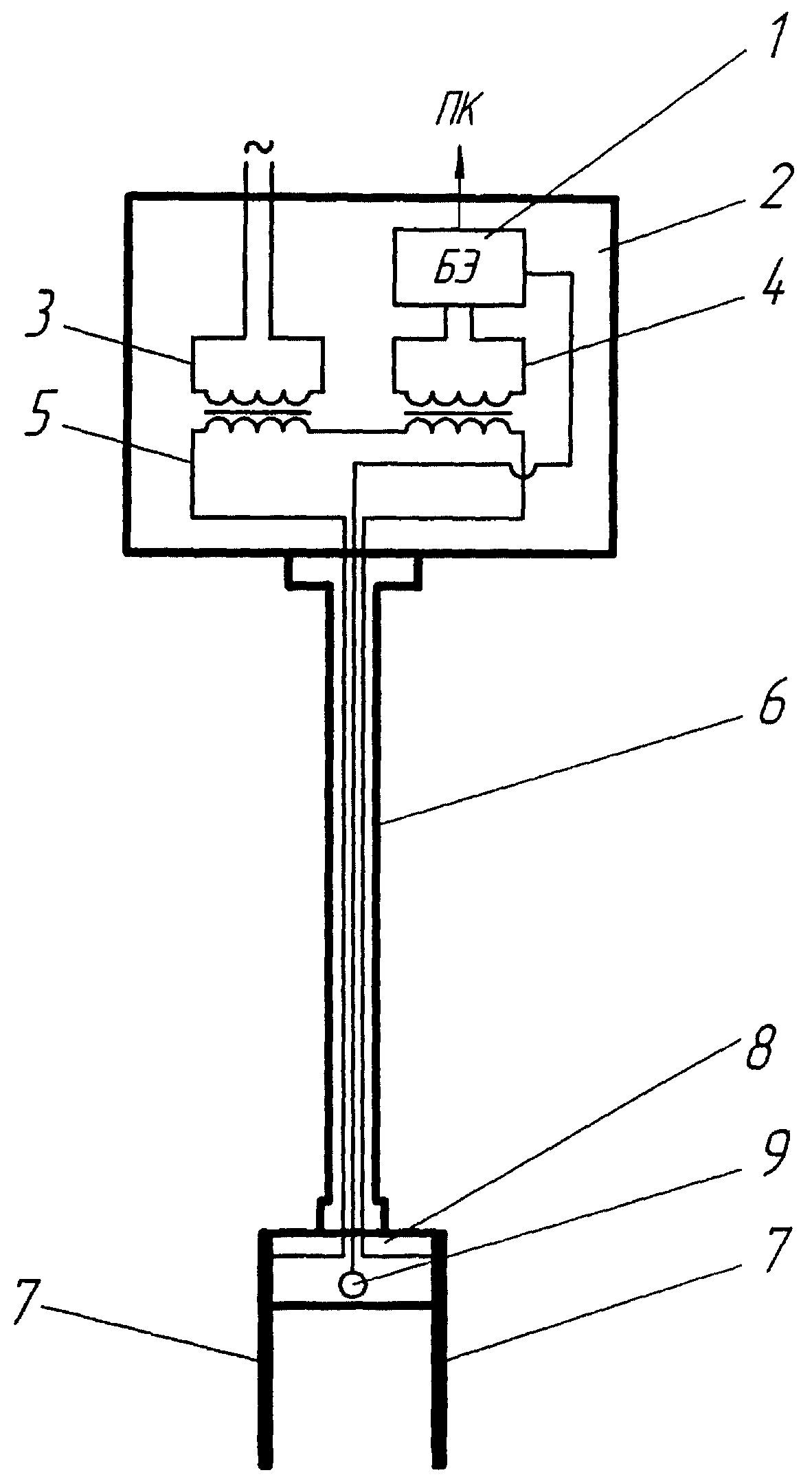
На фиг.1 представлена схема датчика электропроводности.Figure 1 presents a diagram of a conductivity sensor.
Датчик электропроводности состоит из блока электроники 1, размещенного в корпусе 2 с электрическими разъемами для соединения с источником питания и компьютером. В этом же корпусе установлены два трансформатора 3, 4 измерительного преобразователя. Обмотка возбуждения трансформатора 3 соединена с генератором высокочастотного синусоидального напряжения, а выход измерительного трансформатора 4 - с входом блока электроники. Сквозь отверстия обоих трансформаторов проходит провод 5, концы которого пропущены через трубку 6 и соединены с электродами 7, погруженными в контролируемую жидкость. Электроды установлены на изолирующей втулке 8, закрепленной на конце соединительной трубки 6. На этой же изолирующей втулке установлен чувствительный элемент датчика температуры 9, соединенный проводами с входом блока электроники.The conductivity sensor consists of an electronics unit 1 located in the housing 2 with electrical connectors for connection with a power source and a computer. Two transformers 3, 4 of the measuring transducer are installed in the same case. The field winding of the transformer 3 is connected to a high-frequency sinusoidal voltage generator, and the output of the measuring transformer 4 is connected to the input of the electronics unit. A wire 5 passes through the holes of both transformers, the ends of which are passed through a tube 6 and connected to electrodes 7 immersed in a controlled fluid. The electrodes are mounted on an insulating sleeve 8 mounted on the end of the connecting tube 6. A sensing element of a temperature sensor 9 is mounted on the same insulating sleeve, connected by wires to the input of the electronics unit.
Датчик электропроводности работает следующим образом.The conductivity sensor operates as follows.
Обмотка возбуждения трансформатора 3, подключенная к генератору, создает в жидкости, окружающей электроды 7, электрический ток, величина которого пропорциональна электропроводности контролируемой жидкости. Электроды выполнены в виде пластин из нержавеющей стали. Этот ток возбуждает в измерительном трансформаторе 4 переменную ЭДС, величина которой также пропорциональна электропроводности контролируемой жидкости. Полученное синусоидальное напряжение подается на вход блока электроники 1, усиливается, выпрямляется, преобразуется в аналоговый сигнал и передается на компьютер. Сигнал от измерительной части датчика температуры 9 поступает сначала в блок электроники, а затем на компьютер. Сведения о температуре контролируемой жидкости используются в программе обработки данных, что позволяет получить значение электропроводности жидкости, приведенное к нормальным условиям.The excitation winding of the transformer 3, connected to the generator, creates an electric current in the fluid surrounding the electrodes 7, the magnitude of which is proportional to the electrical conductivity of the controlled fluid. The electrodes are made in the form of stainless steel plates. This current excites a variable EMF in the measuring transformer 4, the value of which is also proportional to the conductivity of the controlled fluid. The resulting sinusoidal voltage is supplied to the input of the electronics unit 1, amplified, rectified, converted into an analog signal and transmitted to a computer. The signal from the measuring part of the temperature sensor 9 is supplied first to the electronics unit, and then to the computer. Information about the temperature of the controlled fluid is used in the data processing program, which allows you to get the value of the electrical conductivity of the fluid, reduced to normal conditions.
Предлагаемая конструкция датчика электропроводности имеет следующие преимущества перед аналогами:The proposed design of the conductivity sensor has the following advantages over analogues:
1. Чувствительность датчика электропроводности предлагаемой конструкции определяется размерами электродов и их взаимным расположением и не зависит от размеров тороидальных трансформаторов. Поэтому в конструкции использованы ферритовые кольца меньшего размера с наилучшими характеристиками и с наибольшей температурной стабильностью.1. The sensitivity of the conductivity sensor of the proposed design is determined by the size of the electrodes and their relative position and does not depend on the size of the toroidal transformers. Therefore, the design used smaller ferrite rings with the best characteristics and with the highest temperature stability.
2. Вынос трансформаторов за пределы контролируемой жидкости исключил необходимость их герметизации, что упростило конструкцию датчика и повысило его надежность.2. The removal of transformers outside the controlled fluid eliminated the need for their sealing, which simplified the design of the sensor and increased its reliability.
3. Отпала необходимость в использовании корпуса измерительного преобразователя в виде стакана из нержавеющей стали, что повысило технологичность изготовления датчика и снизило его себестоимость.3. There is no longer any need to use the housing of the measuring transducer in the form of a stainless steel cup, which increased the manufacturability of the sensor and reduced its cost.
4. Электроды в виде пластин из нержавеющей стали при необходимости могут быть легко заменены и позволяют варьировать чувствительность датчика.4. Electrodes in the form of stainless steel plates, if necessary, can be easily replaced and allow you to vary the sensitivity of the sensor.
5. Датчик температуры, установленный рядом с измерительными электродами, позволяет корректировать полученные значения электропроводности с учетом температуры исследуемой жидкости, что повышает достоверность результатов измерений.5. The temperature sensor installed next to the measuring electrodes allows you to adjust the obtained conductivity values taking into account the temperature of the investigated fluid, which increases the reliability of the measurement results.
Claims (2)
Priority Applications (1)
| Application Number | Priority Date | Filing Date | Title |
|---|---|---|---|
| RU2006103382/22U RU55152U1 (en) | 2006-02-06 | 2006-02-06 | ELECTRIC CONDUCTIVITY SENSOR |
Applications Claiming Priority (1)
| Application Number | Priority Date | Filing Date | Title |
|---|---|---|---|
| RU2006103382/22U RU55152U1 (en) | 2006-02-06 | 2006-02-06 | ELECTRIC CONDUCTIVITY SENSOR |
Publications (1)
| Publication Number | Publication Date |
|---|---|
| RU55152U1 true RU55152U1 (en) | 2006-07-27 |
Family
ID=37058648
Family Applications (1)
| Application Number | Title | Priority Date | Filing Date |
|---|---|---|---|
| RU2006103382/22U RU55152U1 (en) | 2006-02-06 | 2006-02-06 | ELECTRIC CONDUCTIVITY SENSOR |
Country Status (1)
| Country | Link |
|---|---|
| RU (1) | RU55152U1 (en) |
Cited By (2)
| Publication number | Priority date | Publication date | Assignee | Title |
|---|---|---|---|---|
| RU2391526C1 (en) * | 2007-10-09 | 2010-06-10 | Гэз Тербайн Иффишенси Свиден Аб | Blow-off drain valve for control of fluid medium flow, flushing system, detecting device of flushing cycle and method of performing flushing cycle |
| RU181054U1 (en) * | 2018-03-16 | 2018-07-04 | Общество с ограниченной ответственностью Научно-производственная компания "Геоэлектроника сервис" | Fluid conductivity sensor |
-
2006
- 2006-02-06 RU RU2006103382/22U patent/RU55152U1/en not_active IP Right Cessation
Cited By (2)
| Publication number | Priority date | Publication date | Assignee | Title |
|---|---|---|---|---|
| RU2391526C1 (en) * | 2007-10-09 | 2010-06-10 | Гэз Тербайн Иффишенси Свиден Аб | Blow-off drain valve for control of fluid medium flow, flushing system, detecting device of flushing cycle and method of performing flushing cycle |
| RU181054U1 (en) * | 2018-03-16 | 2018-07-04 | Общество с ограниченной ответственностью Научно-производственная компания "Геоэлектроника сервис" | Fluid conductivity sensor |
Similar Documents
| Publication | Publication Date | Title |
|---|---|---|
| JP6272500B2 (en) | Improved magnetic core configuration for magnetic flowmeters | |
| RU55152U1 (en) | ELECTRIC CONDUCTIVITY SENSOR | |
| CN120870253A (en) | Single-coil electromagnetic resonance type seawater conductivity measurement sensor and system | |
| CN108957569B (en) | An experimental simulation device for resistivity imaging while drilling | |
| CN208606821U (en) | Anti-tampering New Electromagnetic Flowmeter | |
| RU2401990C2 (en) | Magnetic-inductive flow metre | |
| CN103352690B (en) | A kind of transient electromagnetic well logging transmitting probe | |
| RU181054U1 (en) | Fluid conductivity sensor | |
| RU2398190C2 (en) | Flow sensor and connection element | |
| RU2394231C1 (en) | Inductive transducer of conductivity of sea water | |
| CN203177902U (en) | Online replacing type concealed induction flow meter | |
| CN101063627A (en) | Inductive single point liquid metal level gauge | |
| RU2029922C1 (en) | Device for measuring fuel level | |
| SU1749805A1 (en) | Liquid conductivity inductive sensor | |
| JP2019525390A (en) | Mineral insulated combined magnetic flux loop and B dot wire | |
| CN213932673U (en) | Electromagnetic flowmeter | |
| RU2239792C2 (en) | Inductive level gauge | |
| EP3693710A2 (en) | Full bore magnetic flowmeter assembly with temperature sensing element | |
| JP2001221605A (en) | Device for displaying and outputting piston displacement of fluid pressure cylinder | |
| RU2252397C1 (en) | Inductive level meter | |
| RU2778429C1 (en) | Liquid metal electromagnetic flow meter | |
| RU236333U1 (en) | Differential liquid temperature indicator | |
| RU30002U1 (en) | Device for non-contact pressure measurement in a vessel | |
| RU109555U1 (en) | ELECTROMAGNETIC FLOW METER | |
| US3040571A (en) | Electromagnetic flowmeter for conductive fluids |
Legal Events
| Date | Code | Title | Description |
|---|---|---|---|
| PC1K | Assignment of utility model |
Effective date: 20070702 |
|
| MM1K | Utility model has become invalid (non-payment of fees) |
Effective date: 20120207 |