RU36070U1 - Longer cleaning tank - Google Patents
Longer cleaning tank Download PDFInfo
- Publication number
- RU36070U1 RU36070U1 RU2003127254/20U RU2003127254U RU36070U1 RU 36070 U1 RU36070 U1 RU 36070U1 RU 2003127254/20 U RU2003127254/20 U RU 2003127254/20U RU 2003127254 U RU2003127254 U RU 2003127254U RU 36070 U1 RU36070 U1 RU 36070U1
- Authority
- RU
- Russia
- Prior art keywords
- thread
- tank
- shaft
- hexagon
- cut
- Prior art date
Links
Landscapes
- Mixers Of The Rotary Stirring Type (AREA)
Description
ОПИСАНИЕ ПОЛЕЗНОЙ МОДЕЛИDESCRIPTION OF A USEFUL MODEL
Резервуар с удлинённым сроком службы очищающих устройствLonger cleaning tank
Данная полезная модель относится к технологическому оборудованию молочной и других отраслей пищевой промышленности.This utility model relates to technological equipment of the dairy and other branches of the food industry.
Для производства пищевых продуктов со значительной вязкостью известен вертикальный резервуар с перемешивающим устройством скребкового типа 1. Недостаток данного резервуара состоит в том, что в процессе эксплуатации скребки очищающих устройств сравнительно быстро изнашиваются. При этом возрастает продолжительность охлаждения продукта в резервуаре вследствие неполной очистки охлаждённых слоев с охлаждающей поверхности. Поэтому в известном резервуаре скребки приходится сравнительно часто заменять новыми.For the production of food products with significant viscosity, a vertical tank with a scraper type 1 mixing device is known. The disadvantage of this tank is that the scrapers of the cleaning devices wear out relatively quickly during operation. This increases the duration of the cooling of the product in the tank due to incomplete cleaning of the cooled layers from the cooling surface. Therefore, scrapers in a known reservoir have to be replaced relatively often with new ones.
Для производства пищевых продуктов со средней и малой вязкостью известны резервуары вертикального типа с лопастными мешалками 1. Недостаток известных резервуаров состоит в том, что между краем лопасти и внутренней стенкой резервуара имеется относительно большой зазор. В результате при эксплуатации такого резервуара образуется пристенный слой продукта, плохо перемешиваемый с основной массой продукта. Это отрицательно влияет на коэффициент теплоотдачи на стороне продукта. Особенно сильно пристенный слой ухудшает теплоотдачу при обработке в резервуарах с лопастными мешалками продуктов со средней вязкостью.For the production of food products with medium and low viscosity, vertical type tanks with paddle mixers 1 are known. A disadvantage of the known tanks is that there is a relatively large gap between the edge of the blade and the inner wall of the tank. As a result, during the operation of such a reservoir, a wall layer of the product is formed, poorly mixed with the bulk of the product. This negatively affects the heat transfer coefficient on the product side. Especially strongly wall layer worsens heat transfer during processing in tanks with paddle mixers of products with medium viscosity.
Технический результат, который может быть достигнут в предлагаемой полезной модели, состоит в следующем. Данную полезную модель можно использовать как для обработки пищевых продуктов с большой вязкостью, так и для обработки продуктов со средней и малой вязкостью. При использовании данного резервуара для обработки пишевых продуктов с большой вязкостью мешалка работает, как скребковая. В этом случае технический результат состоит в удлинении срока службы очишаюших устройств и более быстром охлаждении продукта. При использовании предлагаемого резервуара для обработки продз тов со средней и малой вязкостью скребки наход;ятся в непосредственной близости от стенки цилиндра резервуара, но самой стенки не касаются. В этом случае технический результат состоит в увеличении коэффициента теплоотдачи на стороне продукта за счёт уменьшения величины пристенного слоя.The technical result that can be achieved in the proposed utility model is as follows. This utility model can be used both for processing foods with high viscosity and for processing products with medium and low viscosity. When using this tank for processing food products with high viscosity, the mixer works like a scraper. In this case, the technical result consists in lengthening the service life of the cleaning devices and faster cooling of the product. When using the proposed reservoir for processing products with medium and low viscosity, the scrapers are located in the immediate vicinity of the cylinder wall of the reservoir, but the walls themselves do not touch. In this case, the technical result consists in increasing the heat transfer coefficient on the product side by reducing the size of the wall layer.
6 А23 С 3/04 6 A23 C 3/04
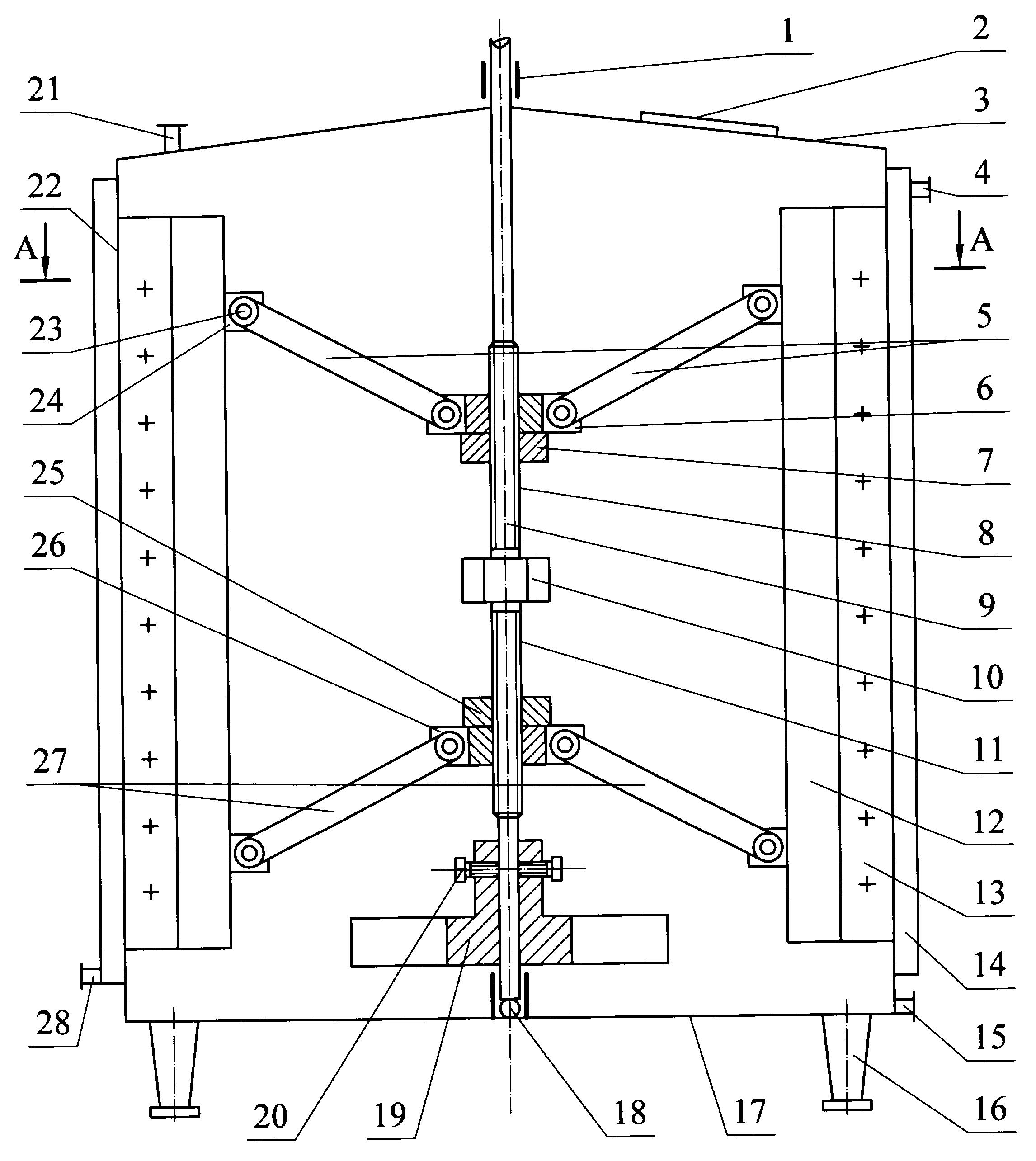
цией резервуара, представленной на фиг. 1 и 2.the tank shown in FIG. 1 and 2.
На фиг. 1 и 2 обозначены: 1 - верхний подшипник; 2 - люк; 3 крышка; 4 - патрубок для отвода хладоносителя; 5 - верхние тяги; 6 - верхний держатель; 7 - верхняя контргайка; 8 - верхняя резьба; 9 - вал; 10 шестигранник; 11 - нижняя резьба; 12 - пластины; 13 - скребки; 14 - охлаждаюш;ая рубашка; 15 - патрубок для отвода продукта; 16 - опоры; 17 дниш;е; 18 - нижний подшипник; 19 - распределитель потока; 20 - стопорные болты; 21 - патрубок для подвода продукта; 22 - цилиндр; 23 - шарнирные соединения; 24 - проушины; 25 - нижняя контргайка; 26 - нижний держатель; 27 - нижние тяги; 28 - патрубок для подачи хладоносителя; 29 основания скребковых устройств.In FIG. 1 and 2 are indicated: 1 - upper bearing; 2 - hatch; 3 cover; 4 - pipe for refrigerant discharge; 5 - upper thrust; 6 - upper holder; 7 - upper lock nut; 8 - upper thread; 9 - shaft; 10 hexagon; 11 - lower thread; 12 - plate; 13 - scrapers; 14 - chill; a shirt; 15 - pipe for product outlet; 16 - supports; 17 bottoms; e; 18 - lower bearing; 19 - flow distributor; 20 - locking bolts; 21 - pipe for supplying the product; 22 - cylinder; 23 - swivel joints; 24 - eyes; 25 - lower locknut; 26 - lower holder; 27 - lower thrust; 28 - pipe for supplying a coolant; 29 bases of scraper devices.
Резервуар состоит из цилиндра 22, снаружи которого имеется охлаждаюш;ая рубашка 14с патрубком для подвода хладоносителя 28 и патрубком для отвода хладоносителя 4. Резервуар имеет дниш;е 17 и крышку 3, и установлен на опорах 16. Скребково-перемешивающее устройство закреплено на валу 9. Вал 9 в нижней части закреплён радиально-упорным подшипником 18, а в верхней части - радиальным подшипником 1. В верхней части вала 9 нарезана верхняя резьба 8, а в нижней части - нижняя резьба 11. В средней части вала к валу приварен шестигранник 10, посредством которого осуш;ествляется проворачивание вала при установке скребков.The tank consists of a cylinder 22, outside of which there is a cooler; shirt 14 with a pipe for supplying coolant 28 and a pipe for removing coolant 4. The tank has a bottom; e 17 and a cover 3, and is mounted on supports 16. The scraper-mixing device is mounted on the shaft 9 Shaft 9 is fixed in the lower part by an angular contact bearing 18, and in the upper part by a radial bearing 1. The upper thread 8 is cut in the upper part of the shaft 9, and the lower thread 11 is cut in the lower part. The hexagon 10 is welded to the shaft in the middle part of the shaft. by which wasp w; there is a rotation of the shaft when installing the scrapers.
Скребковые устройства состоят из оснований 29, пластин 12 и скребков 13. К основаниям скребковых устройств 29 приварены проушины 24.The scraper devices consist of bases 29, plates 12 and scrapers 13. The eyes 24 are welded to the bases of the scraper devices 29.
В верхнем держателе 6 и нижнем держателе 26 имеется центральное отверстие с внутренней резьбой. Направление и шаг резьбы в отверстии верхнего держателя 6 такие же, как и у верхней резьбы 8, направление и шаг резьбы в отверстии нижнего держателя 26 такие же, как и у нижней резьбы 11. Нри помощи резьбы, нарезанной в центральных отверстиях держателей, верхний держатель 6 навинчен на верхнюю резьбу 8, нижний держатель 26 навинчен на нижнюю резьбу 11. Держатели 6 и 26 зафиксированы на резьбе контргайками 7 и 25. По периметру держателей 6 и 26 имеются проушины в количестве четырёх штук. Нроушины расположены друг относительно друга под углом 90°. В проушинах верхнего держателя шарнирно закреплены верхние тяги 5, а в проушинах нижнего держателя - нижние тяги 27. Противоположные концы верхних и нижних тяг при помощи шарниров 23 закреплены в проушинах 24.In the upper holder 6 and the lower holder 26 there is a central hole with an internal thread. The direction and pitch of the thread in the hole of the upper holder 6 are the same as that of the upper thread 8, the direction and pitch of the thread in the hole of the lower holder 26 is the same as that of the lower thread 11. Using the thread cut into the central holes of the holders, the upper holder 6 is screwed onto the upper thread 8, the lower holder 26 is screwed onto the lower thread 11. The holders 6 and 26 are fixed to the thread with lock nuts 7 and 25. There are four eyelets around the perimeter of the holders 6 and 26. Nroushins are located relative to each other at an angle of 90 °. The upper rods 5 are pivotally fixed in the eyes of the upper holder, and the lower rods 27 in the eyes of the lower holder. The opposite ends of the upper and lower rods are hinged 23 in the eyes 24.
Прижатие скребков 13 к стенке цилиндра 22 и их отодвигание от стенки осуществляется за счёт проворачивания держателей 6 и 26 относительно вала 9. Длина участков вала, на которых нарезана верхняя резьба 8 иThe pressing of the scrapers 13 against the wall of the cylinder 22 and their moving away from the wall is carried out by turning the holders 6 and 26 relative to the shaft 9. The length of the sections of the shaft on which the upper thread 8 and
нижняя резьба 11, должна быть такой, чтобы обеспечить перемещение скребков 13 от полного их прижатия к стенке цилиндра резервуара до зазора между стенкой резервуара и передней кромкой скребков в 4 мм.the lower thread 11 must be such as to ensure movement of the scrapers 13 from their full pressing against the wall of the cylinder of the tank to a gap between the wall of the tank and the front edge of the scrapers of 4 mm.
Для резервуаров, рассчитанных на вращение вала по часовой стрелке, верхняя резьба 8 нарезается левой, а нижняя 11 - правой. Для резервуаров, рассчитанных на вращение вала против часовой стрелки, верхняя резьба 8 нарезается правой, а нижняя 11 - левой. Такое направление нарезки резьбы производится из следующих соображений. Если вследствие халатности обслуживающего персонала контргайки 7 и 25 будут затянуты недостаточно плотно, то возможно их самопроизвольное откручивание. В этом случае держатели 6 и 26 из-за сопротивления перемешиваемого продукта провернутся относительно вала в сторону, противоположную вращению вала. При указанном соотношении направления вращения вала и направления нарезки резьбы скребковые устройства вследствие поворота держателей относительно вала отойдут к центру резервуара. Это приведёт к понижению коэффициента теплоотдачи, что будет сразу же отмечено контрольноизмерительными приборами. Однако никакой поломки не произойдёт. При противоположном направлении нарезки резьбы в случае самопроизвольного откручивания контргаек 7 и 25 скребки 13 вследствие поворота держателей относительно вала врежутся в стенки цилиндра 22, что вызовет поломку резервуара и перемешивающих устройств.For tanks designed for clockwise rotation of the shaft, the upper thread 8 is cut to the left, and the lower 11 to the right. For tanks designed to rotate the shaft counterclockwise, the upper thread 8 is cut to the right, and the lower 11 to the left. This direction of threading is made from the following considerations. If, due to the negligence of the operating staff, the locknuts 7 and 25 are not tightened tightly, then their spontaneous unscrewing is possible. In this case, the holders 6 and 26 due to the resistance of the mixed product will turn relative to the shaft in the direction opposite to the rotation of the shaft. With the indicated ratio of the direction of rotation of the shaft and the direction of threading, the scraper devices will move to the center of the tank due to the rotation of the holders relative to the shaft. This will lead to a decrease in the heat transfer coefficient, which will be immediately noted by control and measuring devices. However, no breakdown will occur. In the opposite direction of threading in the case of spontaneous unscrewing of the lock nuts 7 and 25 of the scraper 13 due to the rotation of the holders relative to the shaft, they will crash into the walls of the cylinder 22, which will cause damage to the tank and mixing devices.
К нижней части вала 9 при помощи стопорных болтов 20 присоединён распределитель потока 19. Распределитель потока обеспечивает движение потока по центру резервуара сверху вниз, в нижней части резервуара от центра к периферии и у стенок - снизу вверх. Расположение распределителя потока в нижней части резервуара позволяет обеспечить описанное направление движения продукта как при полном, так и при частичном заполнении резервуара.A flow distributor 19 is connected to the bottom of the shaft 9 with the help of locking bolts 20. The flow distributor provides the flow in the center of the tank from top to bottom, from the center to the periphery in the bottom of the tank and from bottom to top. The location of the flow distributor in the lower part of the tank allows us to provide the described direction of product movement with both full and partial filling of the tank.
Для проникновения обслуживающего персонала внутрь резервуара служит люк 2. Персонал проникает в резервуар через люк 2 при помощи спускной лестницы.For penetration of maintenance personnel inside the tank, hatch 2 is used. Personnel penetrates into the tank through hatch 2 using a drain ladder.
Резервуар функционирует следующим образом. Для обработки пищевых продуктов высокой вязкости скребки 13 устанавливаются вплотную к стенке цилиндра резервуара, и по мере износа скребки периодически пододвигаются к стенке цилиндра. Для обработки продуктов средней и малой вязкости между скребками 13 и стенкой цилиндра резервуара 22 оставляется зазор К4 мм. В этом случае износа скребков не происходит, и пододвигать их к стенкам не требуется.The tank operates as follows. For processing high viscosity food products, the scrapers 13 are mounted close to the cylinder wall of the tank, and as they wear, the scrapers are periodically pushed to the cylinder wall. To process products of medium and low viscosity between the scrapers 13 and the cylinder wall of the tank 22, a clearance of K4 mm is left. In this case, the scrapers do not wear, and it is not necessary to push them to the walls.
Раздвижение и сдвижение скребков осуществляется посредством перемещения держателей 6 и 26 по валу 9. Для этого гаечным ключом фиксируют шестигранник 10 и отворачивают контргайки 7 и 25, Затем, продолжая удерживать шестигранник 10, проворачивают держатели 6 и 26 по резьбе 8 и 11 до обеспечения нужной степени прижатия скребков 13 к стенке цилиндра или до обеспечения необходимого зазора. После этого фиксируют гаечным ключом шестигранник 10 и затягивают контргайки 7 и 25.The sliding and sliding of the scrapers is carried out by moving the holders 6 and 26 along the shaft 9. To do this, fix the hexagon 10 with a wrench and unscrew the lock nuts 7 and 25. Then, while continuing to hold the hexagon 10, rotate the holders 6 and 26 along the threads 8 and 11 until the desired degree pressing the scrapers 13 against the cylinder wall or until the necessary clearance is provided. After that, fix the hexagon 10 with a wrench and tighten the locknuts 7 and 25.
1. Сурков В.Д., Липатов Н.Н., Золотин Ю.П. Технологическое оборудование предприятий молочной промышленности. - М.: Легкая и пищевая промышленность, 1983. - 432 с.1. Surkov V.D., Lipatov N.N., Zolotin Yu.P. Technological equipment of the dairy industry. - M.: Light and food industry, 1983. - 432 p.
ЛитератураLiterature
Claims (1)
Priority Applications (1)
| Application Number | Priority Date | Filing Date | Title |
|---|---|---|---|
| RU2003127254/20U RU36070U1 (en) | 2003-09-08 | 2003-09-08 | Longer cleaning tank |
Applications Claiming Priority (1)
| Application Number | Priority Date | Filing Date | Title |
|---|---|---|---|
| RU2003127254/20U RU36070U1 (en) | 2003-09-08 | 2003-09-08 | Longer cleaning tank |
Publications (1)
| Publication Number | Publication Date |
|---|---|
| RU36070U1 true RU36070U1 (en) | 2004-02-27 |
Family
ID=36296350
Family Applications (1)
| Application Number | Title | Priority Date | Filing Date |
|---|---|---|---|
| RU2003127254/20U RU36070U1 (en) | 2003-09-08 | 2003-09-08 | Longer cleaning tank |
Country Status (1)
| Country | Link |
|---|---|
| RU (1) | RU36070U1 (en) |
-
2003
- 2003-09-08 RU RU2003127254/20U patent/RU36070U1/en not_active IP Right Cessation
Similar Documents
| Publication | Publication Date | Title |
|---|---|---|
| EP3679803B1 (en) | Stirring device of a machine for making liquid or semiliquid food products | |
| EP2684004B1 (en) | Multi-surface heat exchange with vacuum capability and magnetic scrapers | |
| HU184672B (en) | Apparatus for handling wet solid materials, preferably pasty materials with heating or cooling | |
| SE460514B (en) | PELLET FORM WITH ROLLS AND COOLING ORGAN | |
| US6142396A (en) | Nozzel assembly | |
| US20140245774A1 (en) | Extruded ice making machine | |
| RU36070U1 (en) | Longer cleaning tank | |
| CN115317938B (en) | A scraper evaporator | |
| US2585020A (en) | Art of making cracked ice | |
| CN1353292A (en) | Ice cake manufacturing equipment | |
| US6301905B1 (en) | Trough construction | |
| US6206632B1 (en) | Bleed tube for centrifugal pump and method for retrofitting same | |
| JP2010223481A (en) | Ice making equipment | |
| CN102489204A (en) | Double-screw shaft self-cleaning stirring device | |
| GB2116059A (en) | A rotary mixing apparatus | |
| KR101727982B1 (en) | Supply device for liquefied material of vercal type | |
| CN213386458U (en) | A high accuracy spiral feeding device for production of molasses type inorganic compound fertilizer | |
| US1996988A (en) | Method and means for concentrating solutions | |
| JP2006124532A (en) | Gas hydrate cooling device | |
| CN221776631U (en) | A sludge storage and unloading device | |
| US911348A (en) | Ice-cream freezer. | |
| US960614A (en) | Cooling apparatus. | |
| CN219784486U (en) | Livestock and veterinary medicine dispensing device | |
| RU2031687C1 (en) | Heat exchanging apparatus | |
| CN221156698U (en) | Chemical industry safety reaction cauldron |
Legal Events
| Date | Code | Title | Description |
|---|---|---|---|
| MM1K | Utility model has become invalid (non-payment of fees) |
Effective date: 20080909 |