RU32112U1 - Device for measuring liquid metal parameters - Google Patents
Device for measuring liquid metal parameters Download PDFInfo
- Publication number
- RU32112U1 RU32112U1 RU2003105914/20U RU2003105914U RU32112U1 RU 32112 U1 RU32112 U1 RU 32112U1 RU 2003105914/20 U RU2003105914/20 U RU 2003105914/20U RU 2003105914 U RU2003105914 U RU 2003105914U RU 32112 U1 RU32112 U1 RU 32112U1
- Authority
- RU
- Russia
- Prior art keywords
- pipe
- liquid metal
- pipes
- measuring
- measuring liquid
- Prior art date
Links
Landscapes
- Carbon Steel Or Casting Steel Manufacturing (AREA)
Description
УСТРОЙСТВО для ИЗМЕРЕНИЯ ИАРАМЕТРОВ ЖИДКОГО МЕТАЛЛАDEVICE FOR MEASURING LIQUID METAL
Предлагаемая полезная модель относится к черной металлургии, в частности к кислородно-конвертерному производству и может быть использована для замера параметров жидкого металла, например, температуры.The proposed utility model relates to ferrous metallurgy, in particular to oxygen-converter production, and can be used to measure liquid metal parameters, for example, temperature.
Известен измерительный зонд для введения измерительного датчика в жидкую ванну металлургического агрегата, содержащий водоохлаждаемую фурму с размещенной в ней центральной трубой и соединенную с ней контактную трубу для установки датчика, в верхней части контактной трубы установлен конусноцилиндрический отражатель, соединенный с верхним торцом датчика и контактной трубой с образованием незамкнутой полости, в боковой поверхности контактной трубы в пределах незамкнутой полости отражателя выполнены отверстия (патент № 1779264, С21С 5/48).A measuring probe is known for introducing a measuring sensor into a liquid bath of a metallurgical unit, comprising a water-cooled tuyere with a central pipe and a contact pipe connected thereto for mounting the sensor, a conical cylindrical reflector connected to the upper end of the sensor and the contact pipe with the formation of an open cavity, holes are made in the side surface of the contact tube within the open cavity of the reflector (patent No. 1779264, C21C 5/48).
Наиболее близким к предлагаемому устройству является зонд для измерения параметров жидкого металла содержащий коаксиально расположенные трубы, в центральной из которых размещены провода измерительного блока, установленного в головке посредством контактной трубы, средняя и наружная трубы образуют охлаждаемые рубашки, два патрубка, один из которых соединен с кольцевым зазором между центральной и средней трубами, а второй соединен с кольцевым зазором между средней и наружной трубами, дополнительный патрубок, соединенный с кольцевым зазором между средней и наружной трубами, в головке зонда выполнены не менее двух концентрических couQji. // {772ЩС21С5Closest to the proposed device is a probe for measuring the parameters of liquid metal containing coaxially arranged pipes, the central of which houses the wires of the measuring unit installed in the head by means of a contact pipe, the middle and outer pipes form cooled shirts, two pipes, one of which is connected to an annular the gap between the Central and middle pipes, and the second is connected to the annular gap between the middle and outer pipes, an additional pipe connected to the annular Hur between the middle and outer tubes, the probe head formed in at least two concentric couQji. // {772ShchS21S5
Нелостатками приведенных конструкций являются взрывоопасность при прогаре или механическом повреждении фурмы и попадании воды в конвертер, сложность конструкции, недостаточная защищенность измерительного блока от брызг шлака, металла, высокой температуры.The disadvantages of the above designs are the explosion hazard due to burnout or mechanical damage to the lance and water entering the converter, design complexity, insufficient protection of the measuring unit from splash of slag, metal, high temperature.
Поставленная задача решается тем, что устройство для измерения параметров плавки включающее концентрично расположенные трубы, во внутренний из которых размещены провода датчика, а наружная снабжена патрубком, соединенным с кольцевым зазором между внутренней и наружной трубами, причем в нижней части между трубами установлено сопло Лаваля, на внутренней трубе в верхней ее части выполнены сквозные отверстия, а наружная труба снизу имеет конусное сужение.The problem is solved in that the device for measuring the melting parameters includes concentrically arranged pipes, in the inner of which the sensor wires are located, and the outer one is equipped with a pipe connected to the annular gap between the inner and outer pipes, and a Laval nozzle is installed in the lower part between the pipes, through holes are made in the upper part of the inner pipe, and the outer pipe has a conical narrowing at the bottom.
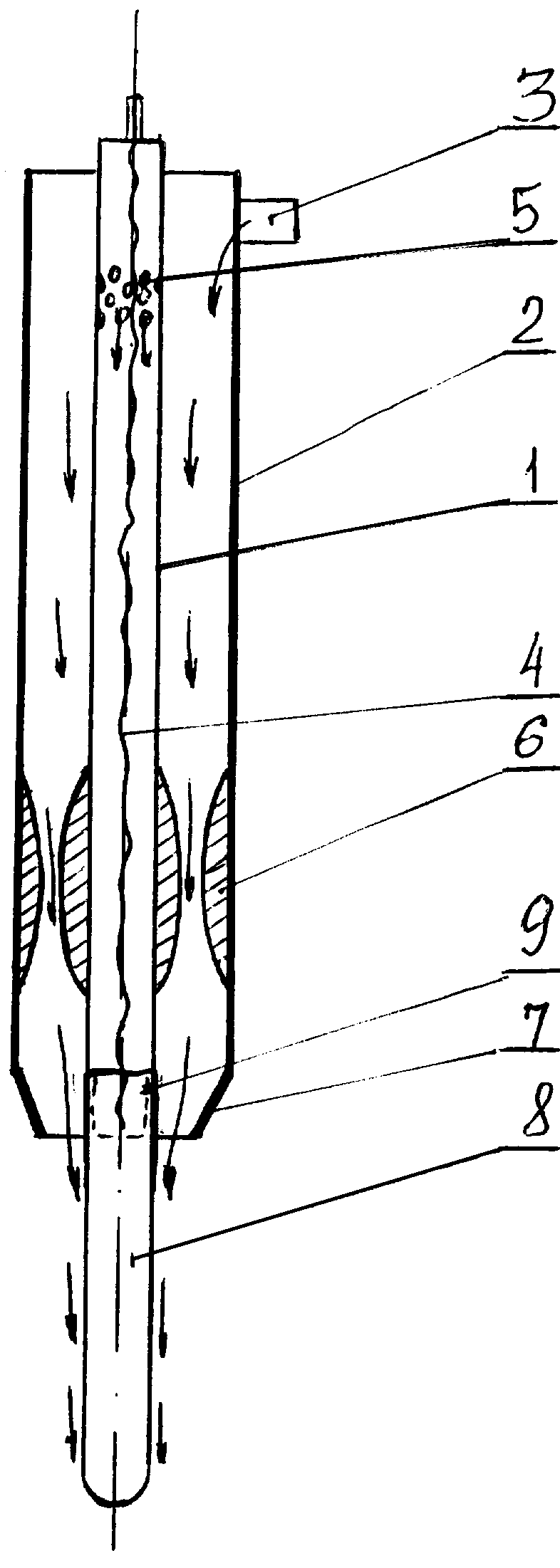
Сущность полезной модели поясняется чертежом, где схематично изображен общий вид устройства.The essence of the utility model is illustrated by the drawing, which schematically shows a General view of the device.
Устройство состоит из двух концентрично собранных труб - внутренней 1 и наружной 2. В верхней части наружной трубы имеется патрубок 3. Во внутренней трубе 1 размещены провода 4 измерительного блока 8. На внутренней трубе 1 в верхней части выполнены сквозные отверстия 5. В нижней части между трубами 1 и 2 установлено сопло Лаваля 6. Наружная труба снизу имеет конусное сужение 7. Измерительный блок 8 подсоединен к внутренней трубе 1, например, с помощью резьбового соединения 9.The device consists of two concentrically assembled pipes - inner 1 and outer 2. In the upper part of the outer pipe there is a pipe 3. In the inner pipe 1 there are wires 4 of the measuring unit 8. On the inner pipe 1 in the upper part there are through holes 5. In the lower part between pipes 1 and 2 have a Laval nozzle 6. The outer pipe bottom has a conical narrowing 7. The measuring unit 8 is connected to the inner pipe 1, for example, using a threaded connection 9.
Устройство работает следующим образом: сжатый азот через патрубок 3 подают в кольцевой зазор между внутренней и наружной трубами и проходя по нему охлаждает устройство. Через отверстия 5 во внутренней трубе азот заполняет полость трубы 1 с приводом 4 измерительного блока 8, создавая в ней защитную среду. Азот, перемещаясь по кольцевому зазору между трубами 1 и 2 проходит сопло Лаваля 6 и, понижая свою температуру, охлаждает нижнюю, наиболее теплонапряженную часть устройства.The device operates as follows: compressed nitrogen through the pipe 3 is fed into the annular gap between the inner and outer pipes and, passing through it, cools the device. Through holes 5 in the inner pipe, nitrogen fills the cavity of the pipe 1 with the drive 4 of the measuring unit 8, creating a protective environment in it. Nitrogen, moving along the annular gap between the pipes 1 and 2, passes the Laval nozzle 6 and, lowering its temperature, cools the lower, most heat-stressed part of the device.
Далее азот проходит через нижнюю конусную часть 7, которая придает направление азоту, направлял его на измерительный блок 8, защищая его от воздействия брызг шлака, металла и высокой температуры.Next, the nitrogen passes through the lower conical part 7, which gives direction to the nitrogen, sent it to the measuring unit 8, protecting it from the effects of splash of slag, metal and high temperature.
На Магнитогорском металлургическом комбинате было изготовлено предлагаемое устройство и установлено на конвертерах 1,2,3. Для охлаждения использовали азот с давлением 1,0 МПа. Применение устройства позволило повысить ее взрывобезопасность, т.к. в процессе в качестве охладителя используютAt the Magnitogorsk Iron and Steel Works, the proposed device was manufactured and installed on converters 1,2,3. For cooling, nitrogen was used with a pressure of 1.0 MPa. The use of the device allowed to increase its explosion safety, as in the process as a cooler use
только азот, тем самым увеличилась надежность работы устройства, снизились аварии, увеличилось производство, упростилась конструкция и увеличился срок службы устройства.only nitrogen, thereby increasing the reliability of the device, decreased accidents, increased production, simplified the design and increased the life of the device.
Claims (1)
Priority Applications (1)
| Application Number | Priority Date | Filing Date | Title |
|---|---|---|---|
| RU2003105914/20U RU32112U1 (en) | 2003-03-03 | 2003-03-03 | Device for measuring liquid metal parameters |
Applications Claiming Priority (1)
| Application Number | Priority Date | Filing Date | Title |
|---|---|---|---|
| RU2003105914/20U RU32112U1 (en) | 2003-03-03 | 2003-03-03 | Device for measuring liquid metal parameters |
Publications (1)
| Publication Number | Publication Date |
|---|---|
| RU32112U1 true RU32112U1 (en) | 2003-09-10 |
Family
ID=35561088
Family Applications (1)
| Application Number | Title | Priority Date | Filing Date |
|---|---|---|---|
| RU2003105914/20U RU32112U1 (en) | 2003-03-03 | 2003-03-03 | Device for measuring liquid metal parameters |
Country Status (1)
| Country | Link |
|---|---|
| RU (1) | RU32112U1 (en) |
-
2003
- 2003-03-03 RU RU2003105914/20U patent/RU32112U1/en not_active IP Right Cessation
Similar Documents
| Publication | Publication Date | Title |
|---|---|---|
| DE60122318D1 (en) | DEVICE FOR BLOWING SOLID MATERIAL PARTICLES INTO A VESSEL | |
| US3080755A (en) | Metallurgical process control | |
| CN204550682U (en) | A kind of non-ferrous metal oxygen-enriched bottom-blowing oxygen lance | |
| RU32112U1 (en) | Device for measuring liquid metal parameters | |
| US3161499A (en) | Metallurgical process control | |
| CN109883206B (en) | High-speed cooling device for smelting of vacuum consumable furnace | |
| US4450986A (en) | Apparatus for unplugging a vessel discharge port | |
| CN201304475Y (en) | Continuous casting device for producing round billet with diameter being more than or equal to Phi 800 mm on straight-form conticaster | |
| CN213614119U (en) | Device for improving oxygen-burning drainage accuracy of continuous casting steel ladle | |
| FR2402848A1 (en) | VERTICAL OVEN TO PRODUCE A LOW OXYGEN POWDER FOR POWDER METALLURGY | |
| CN219032232U (en) | Online measurement system for thickness of cooling wall of blast furnace | |
| CN217990874U (en) | Crystallizer diversion water jacket | |
| CN212042647U (en) | Airtight cover for casting 1Cr17Ni2 or 5CrNiMoV molten steel | |
| RU54373U1 (en) | MEASURING LONG | |
| EP1315841A1 (en) | Process for the metallurgical treatment of molten steel in a converter with oxygen top blown | |
| CN2863815Y (en) | Oxygen lance nozzle for forging die casting billet | |
| RU57744U1 (en) | OXYGEN BURNER AND METAL TEMPERATURE MEASUREMENT | |
| US3394928A (en) | Combination oxygen lance clamp and descaling device | |
| SU908839A1 (en) | Tuyere blasting molden metal | |
| SU500239A1 (en) | Lance for deep metal purging | |
| CN224105904U (en) | Novel electroslag remelting furnace | |
| CN217922175U (en) | Converter sublance copper head sealing device | |
| RU50892U1 (en) | DEVICE FOR PROTECTING JETS FROM SECONDARY OXIDATION DURING CONTINUOUS CASTING | |
| RU1772169C (en) | Probe for measurement of liquid metal parameters | |
| RU7408U1 (en) | TIP OF OXYGEN-CONVERTER LASER |
Legal Events
| Date | Code | Title | Description |
|---|---|---|---|
| MM1K | Utility model has become invalid (non-payment of fees) |
Effective date: 20040304 |