RU31455U1 - A device for detecting sonar signals and masking their reflection from a marine moving object - Google Patents
A device for detecting sonar signals and masking their reflection from a marine moving object Download PDFInfo
- Publication number
- RU31455U1 RU31455U1 RU2003102755/20U RU2003102755U RU31455U1 RU 31455 U1 RU31455 U1 RU 31455U1 RU 2003102755/20 U RU2003102755/20 U RU 2003102755/20U RU 2003102755 U RU2003102755 U RU 2003102755U RU 31455 U1 RU31455 U1 RU 31455U1
- Authority
- RU
- Russia
- Prior art keywords
- signal
- unit
- block
- output
- inputs
- Prior art date
Links
Description
Устройство для обнаружения гидролокационных сигналов и маскировки их отражения от морского подвижного объектаA device for detecting sonar signals and masking their reflection from a marine moving object
Полезная модель относится к гидроакустической технике, а конкретнее к устройствам гидроакустической маскировки и к устройствам обнаружения гидролокационных сигналов.The invention relates to sonar technology, and more particularly to sonar masking devices and sonar detection devices.
Киты с помощью гидролокационных сигналов определяют дистанцию до китобойного судна и уходят из этой акватории смотрите, например, М.Д.Трусканов, Е.В.Шишкова, М.Н.Щербино. Новое в технике рыболокации. Обзор литературы. - М.: Пищевая промышленность. 1967. - 136 с. Поэтому целесообразно эхосигнал от корпуса и кильватерной струи китобойного судна маскировать под морскую реверберацию. Как известно, морская реверберация - это наблюдаемый в точке приема случайный процесс, обусловленный рассеянием излучаемого сигнала на неоднородностях водной среды и неровностях ее границ В.В.Ольшевский. Статистические свойства морской реверберации. - М.: Паука, 1966. - 208 с. Имитируемые поверхностная, донная и объемная реверберации должны быть настолько значительны, что кит не сможет заметить полезный для него эхосигнал от судна на ее фоне. Кроме того, команда китобойного судна должна иметь возможность обнаружить гидролокационный сигнал кита.With the help of sonar signals, whales determine the distance to the whaling vessel and leave this water area, see, for example, M.D. Truskanov, E.V. Shishkova, M.N. Scherbino. New in fishing technique. Literature review. - M .: Food industry. 1967 .-- 136 p. Therefore, it is advisable to mask the echo from the hull and wake of the whaling vessel under marine reverb. As you know, marine reverberation is a random process observed at the receiving point, due to the scattering of the emitted signal from the inhomogeneities of the aquatic environment and the unevenness of its boundaries V.V. Olshevsky. The statistical properties of marine reverb. - M .: Spider, 1966 .-- 208 p. The simulated surface, bottom and volumetric reverberations should be so significant that the whale will not be able to notice a useful echo from the vessel against its background. In addition, the whaling crew should be able to detect the whale's sonar signal.
Известны системы противодействия, предназначенные для создания помех системам извлечения информации путем излучения мешающих сигналов, содержащие последовательно соединенные генератор и излучатель смотрите, например, Л.С.Гуткин. Современная радиоэлектроника и ее проблемы. - М. : Сов.радио, 1980. - 83 с. Однако, такое противодействие не пригодно для маскировки эхосигналов от китобойного судна, так как будет сильнее отпугивать китов.Known counteraction systems designed to interfere with information extraction systems by emitting interfering signals containing a generator and emitter connected in series see, for example, L. S. Gutkin. Modern electronics and its problems. - M.: Sov.radio, 1980 .-- 83 p. However, such a counteraction is not suitable for masking echo signals from a whaling vessel, since it will more strongly scare away whales.
G 01 S 7/40 G 01 SI 5/58G 01 S 7/40 G 01 SI 5/58
Известна Система для моделирования принимаемых радиолокационных сигналов, отраженных от поверхности земли из патента США № 3131247, 1964 г., которая содержит последовательно соединенные линию случайной задержки, радиолокационный передатчик и индикатор. Однако эта система не может в полной мере решить задачу маскировки эхосигнала.Known System for modeling the received radar signals reflected from the surface of the earth from US patent No. 3131247, 1964, which contains a series-connected random delay line, a radar transmitter and an indicator. However, this system cannot fully solve the problem of masking the echo signal.
Известно устройство активной маскировки любого звучащего и рассеиваюпдего тела от падающих на него звуковых волн Г.Д.Малюжинец. Простейшая модель поглощающей и прозрачной решетки с обратной связью. М.: Труды Акустического института, выпуск 15, 1971. Это устройство содержит последовательно соединенные генератор и окружающее тело сеть приемно-излучаюпщх электроакустических преобразователей монопольного и дипольного типов, у которых распределение амплитуд и фаз, управляемое маскируемым звуком, происходило так, чтобы наблюдалось гашение падающего на тело звука в соответствующих областях пространства. Однако, техническая реализация связана с исключительными трудностями, обусловленными необходимостью использования очень большого количества электроакустических преобразователей, располагаемых через половину длины звуковой волны, и необходимостью обеспечить распределение фаз и амплитуд с большой точностью.A device is known for actively masking any sounding and dissipating body from the sound waves incident on it by G.D. Malyuzhinets. The simplest model of an absorbing and transparent lattice with feedback. M .: Proceedings of the Acoustic Institute, issue 15, 1971. This device contains a series-connected generator and a surrounding network of receiving-emitting mono-pole and dipole-type electroacoustic transducers, in which the distribution of amplitudes and phases, controlled by masked sound, occurs so that the attenuation of the incident on the body of sound in the corresponding areas of space. However, the technical implementation is associated with exceptional difficulties due to the need to use a very large number of electro-acoustic transducers located at half the sound wavelength, and the need to ensure the distribution of phases and amplitudes with great accuracy.
В качестве прототипа выбрана система противодействия, содержащая самоходные или дрейфующие имитаторы отраженных сигналов от морских подвижных объектов (МПО) с последовательно соединенными приемным и передающим трактами. Они обеспечивают отвлечение на себя противолодочного оружия с гидроакустическими системами самонаведения А.П.Вержикловский и др. Краткий словарь по радиоэлектронике. - М.: Воениздат, 1980. - 410 с. Однако это устройство-прототип не обеспечивает маскировку самого крггобойного судна от гидролокац1ш его китом.As a prototype, a counteraction system was selected containing self-propelled or drifting simulators of reflected signals from marine moving objects (MPOs) with receiving and transmitting paths connected in series. They provide distraction for anti-submarine weapons with sonar homing systems A.P. Verzhiklovsky and others. A brief dictionary on radio electronics. - M .: Military Publishing House, 1980 .-- 410 p. However, this prototype device does not provide for camouflage of the most oblique vessel from its whale sonar.
верберационную помеху. Причем, под обнаружением понимается определение характера и параметров локационного сигнала и определение координат.verbal interference. Moreover, the detection refers to the determination of the nature and parameters of the location signal and the determination of coordinates.
Для решения поставленной задачи предлагается устройство для обнаружения гидролокационных сигналов и маскировки их отражений, содержащее как и устройство-прототип от МПО, приемный и излучаюпщй гидроакустические тракты. В устройство введены блоки памяти принятого гидроакустического сигнала с учётом эффекта Дошшера, вход которого соединен с выходом приемного гидроакустического тракта, также введены параллельно соединенные блок формирования сигнала подавления и искажения эхосигнала, блок имитации объёмной реверберации, блок имитации поверхностной реверберации, блок имитации донной реверберации, входы которых соединены с выходами блока памяти принятого гидролокационного сигнала с учётом эффекга Допплера, а выходы соединены с излучающим гидроакустическим трактом, также введены последовательно соединенные блок анализа принятого сигнала, вход которого соединен с выходом блока памяти принятого гидролокационного сигнала с эффекта Допплера, и блок расчета траекторией распространения сигнала и оценки дистанции до источника сигнала, вывод которого соединен со вторыми входами блоков имитации поверхностной реверберации и донной реверберации, также введен блок управления, синхровходы и синхровыходы которого соединены со всеми блоками устройства.To solve this problem, a device is proposed for detecting sonar signals and masking their reflections, containing, like the prototype device from MPO, receiving and radiating sonar paths. The memory blocks of the received hydroacoustic signal are introduced into the device taking into account the Doscher effect, the input of which is connected to the output of the receiving hydroacoustic path, the parallel-connected block for generating the signal for suppressing and distorting the echo signal, the block for simulating the volume reverb, the block for simulating the surface reverb, the block for simulating the bottom reverb, inputs which are connected to the outputs of the memory unit of the received sonar signal taking into account the Doppler effect, and the outputs are connected to the emitting sonar The path also introduced a series-connected block for analyzing the received signal, the input of which is connected to the output of the memory block of the received sonar signal from the Doppler effect, and a block for calculating the signal propagation path and estimating the distance to the signal source, the output of which is connected to the second inputs of the surface reverb simulation blocks and bottom reverb, also introduced a control unit, the clock inputs and clock outputs of which are connected to all units of the device.
Блок памяти принятого гидроакустического сигнала с учетом эффекта Допплера содержит последовательно соединенные оперативное запоминающее устройство (ОЗУ) принятого гидролокационного сигнала, вход которого соединен с приемным гидроакустическим трактом, блок расчета эхосигнала и ОЗУ эхосигнала, выходы которого соединены со входами блока формирования сигнала подавления эхосигнала и блока имитации объемной реверберации, блока имитации поверхностной реверберации, блоки имитации донной реверберации и блока анализа принятого сигнала, также введен блок расчетаThe memory block of the received hydroacoustic signal, taking into account the Doppler effect, contains a serially connected random access memory (RAM) of the received sonar signal, the input of which is connected to the receiving sonar path, the echo signal calculation unit and the echo signal RAM, the outputs of which are connected to the inputs of the echo cancellation signal generating unit and the simulation unit volume reverb, surface reverb simulation unit, bottom reverb simulation unit, and received signal analysis unit, t A calculation block has also been introduced.
Допплеровского сдвига частоты от движения МПО, вход которого соединен с лагом МПО, а выход соединен с блоком расчета эхосигнала.Doppler frequency shift from the MPO movement, the input of which is connected to the MPO lag, and the output is connected to the block of calculation of the echo signal.
Блок формирования сигнала нодавления эхосигнала содержит последовательно соединенные фазовращатель, вход которого соединен со входом блока намяти принятого гидролокационного сигнала с учетом эффекта Допплера, блок памяти эхосигнала, повернутого на а° и цифроаналоговый преобразователь (ЦАП), выход которого соединен со входом излучающего гидроакустического тракта.The echo cancellation signal generating unit contains a phase shifter connected in series, the input of which is connected to the input of the received sonar signal memory unit taking into account the Doppler effect, an echo signal memory unit rotated by a ° and a digital-to-analog converter (DAC), the output of which is connected to the input of the emitting sonar path.
Учитывая, что источник гидролокащюнного звука может создавать сложный сигнал, другое исполнение блок-схемы формирования сигнала подавления эхосигнала может содержать узкополосный спектроанализатор, вход которого соединен с блоком памяти гидролокационного сигнала, также содержит m параллельно соединенных фазовращателей, входы которых соединены с выходами узкополосного спектроанализатора, также содержит последовательно соединенные блок памяти спектральных составляющих эхосигнала, повернутых на а°, входы которого соединены с выходами m фазовращателей, и цифроаналоговый преобразователь, выход которого соединен с излучающим гидроакустическим трактом.Given that the sonar sound source can create a complex signal, another embodiment of the block diagram for generating an echo cancellation signal can contain a narrow-band spectrum analyzer, the input of which is connected to the sonar signal memory block, also contains m parallel-connected phase shifters, the inputs of which are connected to the outputs of the narrow-band spectrum analyzer, also contains a series-connected memory block of the spectral components of the echo signal rotated by a °, the inputs of which are connected to the output E m phase shifters, and a digital to analog converter whose output is connected to the radiating hydroacoustic tract.
Блок имитации объемной реверберации содержит последовательно соединенные блок случайной задержки, вход которого соединен с выходом блока памяти принятого гидроакусического сигнала с учетом эффекта Допплера, и цифро-аналоговый преобразователь, выход которого соединен с излучающим гидроакустическим трактом.The volume reverb simulation unit contains a random delay unit connected in series, the input of which is connected to the output of the received sonar signal memory unit taking into account the Doppler effect, and a digital-to-analog converter, the output of which is connected to the emitting sonar path.
Блок имитации поверхностной реверберации содержит параллельно соединенные п пар регулируемых блоков временных задержек и случайных задержек, сумматор и цифроаналоговый преобразователь, выход которого соединен со входом излучающего гидроакустического тракта, а входы регулируемых временных задержек соединены с выходом блока памяти принятого гидроакустического сигнала, вторые входы всех регулируемых временныхThe surface reverb simulation block contains parallel-connected n pairs of adjustable blocks of time delays and random delays, an adder and a digital-to-analog converter, the output of which is connected to the input of the emitting hydroacoustic path, and the inputs of the adjustable time delays are connected to the output of the memory block of the received hydroacoustic signal, the second inputs of all adjustable time
0 задержек соединены с выходами блока оценки траекторий распространения эхосигнала, также введен блок данных о волнении моря, выходы которого соединены со вторыми входами случайных задержек.0 delays are connected to the outputs of the block for evaluating the propagation paths of the echo signal; a block of data on sea waves is also introduced, the outputs of which are connected to the second inputs of random delays.
Блок имитации данной реверберации содержит последовательно соединенные п пар блоков регулируемых временных задержек и блоков случайных задержек, сумматор и цифроаналоговый нреобразователь, выход которого соединен со входом излучающего гидроакустического тракта, входы регулируемых временных задержек соединены с выходом блока памяти принятого гидроакустического сигнала с учетом эффекта Допплера, вторые входы всех регулируемых временных задержек соединены с выходом блока расчета траекторий распространения сигналов, также введен блок данных о изрезанности дна моря в данной акватории, выходы которого соединены со вторыми входами всех п блоков случайных задержек.The simulation block of this reverb contains sequentially connected pairs of blocks of adjustable time delays and blocks of random delays, an adder and a digital-to-analog converter, the output of which is connected to the input of the emitting hydroacoustic path, the inputs of the adjustable time delays are connected to the output of the memory block of the received hydroacoustic signal taking into account the Doppler effect, the second the inputs of all adjustable time delays are connected to the output of the block for calculating the propagation paths of signals; ok data on the severity of the seabed in this area, the outputs of which are connected to the second inputs of all n blocks of random delays.
Блок анализа принятого гидроакустического сигнала содержит параллельно соединенные блок анализа частоты и формы сигнала, блок анализа амплитуды сигнала, входы которых соединены с выходом блока памяти принятого гидроакустического сигнала с учетом эффекта Допплера, также содержит оперативное запоминающее устройство (ОЗУ), входы которого соединены с блоком анализа частоты и формы сигнала, блоком анализа амплитуды сигнала, а выход соединен со входом блока расчета траекторий распространения сигнала и оценки дистанции до источника сигнала.The received hydroacoustic signal analysis unit contains a parallel connected frequency and waveform analysis unit, a signal amplitude analysis unit, the inputs of which are connected to the output of the received hydroacoustic signal memory unit taking into account the Doppler effect, also contains random access memory (RAM), the inputs of which are connected to the analysis unit frequency and waveform, the analysis unit of the amplitude of the signal, and the output is connected to the input of the unit for calculating the propagation paths of the signal and estimate the distance to the signal source .
Блок расчета траекторий распространения сигнала и оценки дистанции до источника содержит последовательно соединенные измеритель скорости звука (скоростемер), блок памяти вертикального распределения скорости звука (ВРСЗ), блок расчета траектории распространения сигнала, блок расчета дистанции до источника сигнала, выходы блоков расчета соединены со входами блоков имитации поверхностной и донной реверберации, а второй, третий и четвертый входы блока расчета дистанции до источника сигнала соединены соответственно с выходами блока анализа принятого сигнала, блокаThe block for calculating the propagation paths of the signal and estimating the distance to the source contains a sound velocity meter (speed meter) connected in series, a memory block for the vertical distribution of the sound velocity (VRSS), a block for calculating the signal propagation path, a block for calculating the distance to the signal source, the outputs of the calculation blocks are connected to the inputs of the blocks simulations of surface and bottom reverberation, and the second, third and fourth inputs of the unit for calculating the distance to the signal source are connected respectively to the outputs of the anal unit from the received signal, block
данных о волнении моря и блоком данных о изрезанности дна, индикатор также содержит блок памяти коэффициента затухания звука, выход которого соединен с пятым входом блока расчета дистанции до источника сигнала.data on sea waves and a block of data on the bottom roughness, the indicator also contains a block of sound attenuation coefficient memory, the output of which is connected to the fifth input of the distance calculation unit to the signal source.
Излучаюпщй гидроакустический тракт содержит сумматор, первый, второй, третий и четвертый входы которого соединены соответственно с выходами блоков формирования сигнала для подавления эхосигнала, блока имитации объемной реверберации, блока имитации поверхностной реверберации, блока имитации донной реверберации, также содержит п параллельно соединенных усилителей и п излучателей сигнала маскировки, причем входы всех п усилителей подсоединены к выходу сумматора, а выходы соединены со входами п излучателей соответственно.The emitted hydroacoustic path contains an adder, the first, second, third and fourth inputs of which are connected respectively to the outputs of the signal conditioning blocks for suppressing the echo signal, the volume reverb simulation unit, the surface reverb simulation unit, the bottom reverb simulation unit, also contains n parallel connected amplifiers and n emitters masking signal, and the inputs of all n amplifiers are connected to the output of the adder, and the outputs are connected to the inputs of n emitters, respectively.
Блок расчета дистанции до источника сигнала содержит последовательно соединенные блок определения акустического давления принятого сигнала, первый вход которого соединен с выходом блока анализа принятого сигнала, и блок решения уравнения, выход которого соединен со входами блока имитации поверхностной и блока имитации донной реверберации, а второй вход блока решения уравнения соединен с выходом блока памяти коэффициента затухания звука, также содержит блок памяти частотной характеристики чувствительности приемного тракта, выход которого соединен со вторым входом блока определения акустического давления принятого сигнала, также содержит блок определения радиус-вектора характеристики направленности (ХН) приемной системы, вход которого соединен с приемным гидроакустическим трактом, а выход - с блоком решения уравнения, также содержит блок расчета фактора аномалии, вход которого соединен с выходом блока расчета траекторий распространения сигнала, а выход - с четвертым входом блока решения уравнения.The unit for calculating the distance to the signal source contains a series-connected unit for determining the acoustic pressure of the received signal, the first input of which is connected to the output of the analysis unit for the received signal, and an equation solving unit, the output of which is connected to the inputs of the surface simulation unit and the bottom reverb simulation unit, and the second input of the unit solving the equation is connected to the output of the sound attenuation coefficient memory block, also contains a memory block of the frequency response sensitivity of the receive path, the output to which is connected to the second input of the unit for determining the acoustic pressure of the received signal, also contains a unit for determining the radius vector of the directivity characteristic (XI) of the receiving system, the input of which is connected to the receiving hydroacoustic path, and the output to the unit for solving the equation, also contains a block for calculating the anomaly factor, whose input is connected to the output of the block for calculating the propagation paths of the signal, and the output to the fourth input of the block for solving the equation.
Другое исполнения блока расчета дистанции до источника сигнала содержит параллельно соединенные блок определения задержек прихода водных , блок определения задержек отраженных лучей, блок определенияAnother embodiment of the unit for calculating the distance to the signal source contains a parallel-connected unit for determining delays in the arrival of water, a unit for determining delays in reflected rays, a unit for determining
углов прихода водных лучей, входы которых соединены с приемным гидроакустическим трактом, эхолот МПО, выходы этих блоков и эхолота соединены с первым, вторым, третьим и четвертым входами вводимого блока расчета дистанции по углам и временам задержек лучей, вход которого соединен со входами блока имитации поверхностной реверберации и блока объемной реверберации.angles of arrival of water rays, the inputs of which are connected to the receiving sonar tract, the MPO echo sounder, the outputs of these blocks and the echo sounder are connected to the first, second, third and fourth inputs of the input unit for calculating the distance according to the angles and time delays of the rays, the input of which is connected to the inputs of the surface simulation unit reverb and volumetric reverb unit.
Техническим результатом полезной модели является обеспечение невозможности классифицировать МПО, а также обеспечение обнаружения источника гидролокациошюго сигнала.The technical result of the utility model is to ensure the inability to classify MPO, as well as to ensure detection of the source of the sonar signal.
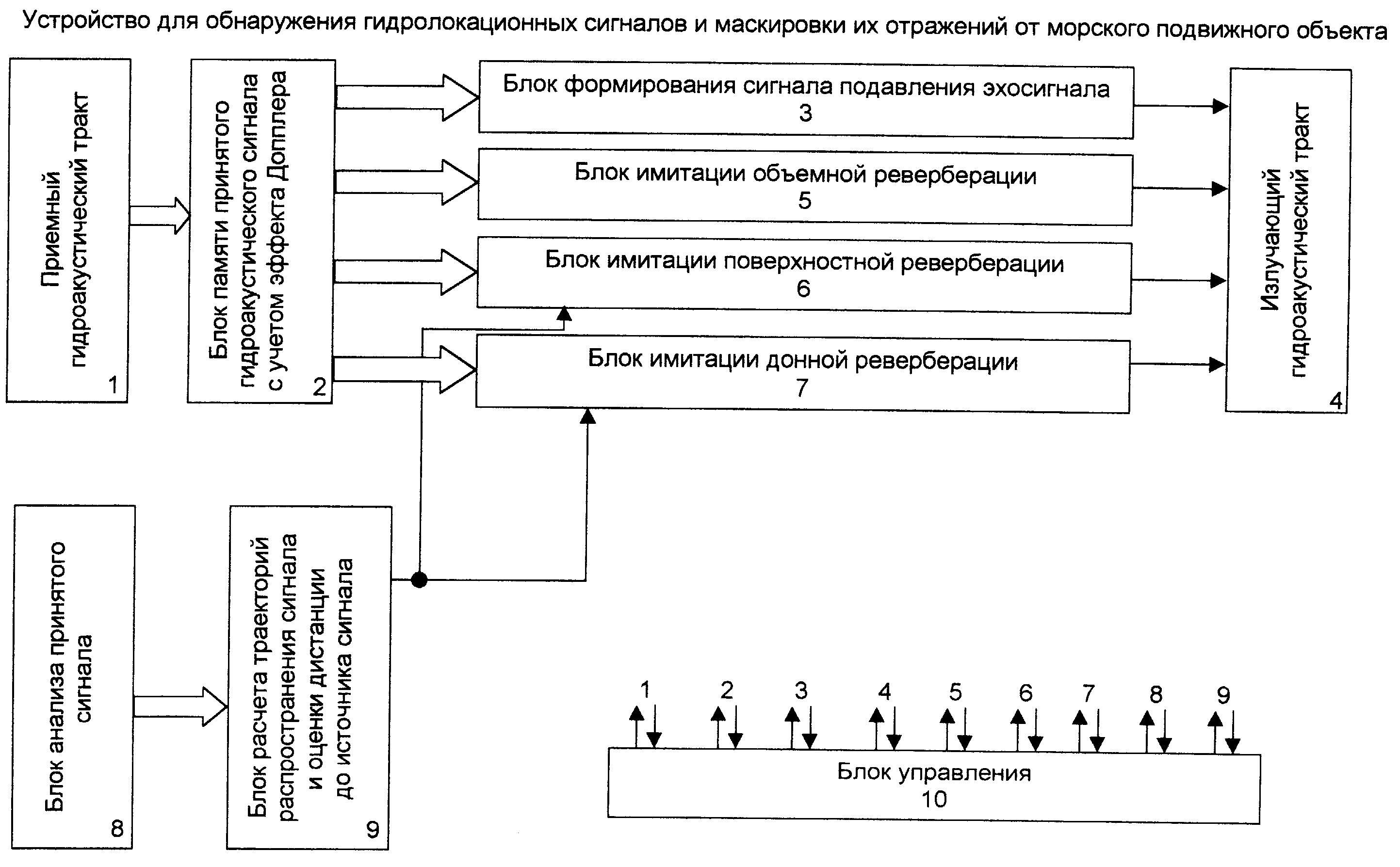
На фигЛ приведена блок-схема предлагаемого устройства для обнаружения гидролокационных сигналов и маскировки их отражений от морского подвижного объекта.On Fig shows a block diagram of the proposed device for detecting sonar signals and masking their reflections from a marine moving object.
На фиг.2 приведена блок-схема блока памяти принятого гидроакустического сигнала с учетом эффекта Допплера.Figure 2 shows a block diagram of a memory block of a received sonar signal taking into account the Doppler effect.
На фиг.З приведена блок-схема формирования сигнала подавления эхосигнала.Fig. 3 shows a block diagram of the formation of an echo cancellation signal.
На фиг.4 приведено другое исполнение блок-схемы формирования сигнала подавления эхосигнала.Figure 4 shows another embodiment of the block diagram of the formation of the signal suppression of the echo signal.
На фиг. 5 приведена блок-схема блока имитации объемной реверберации.In FIG. 5 is a block diagram of a volume reverb simulation unit.
На фиг.6 приведена блок-схема имитации поверхностной реверберации.Figure 6 shows a block diagram of a simulation of surface reverb.
На фиг.7 приведена блок-схема блока имитации донной реверберации.Figure 7 shows a block diagram of a block simulating bottom reverb.
На фиг.8 приведен блок анализа принятого гидроакустического сигнала.On Fig shows the block analysis of the received sonar signal.
На фиг.9 приведена блок-схема блока расчета траекторий распространения сигнала и дистанции до источника сигнала.Figure 9 shows a block diagram of a unit for calculating the signal propagation paths and the distance to the signal source.
На фиг. 11 приведена блок-схема блока расчета дистанции до источника сигнала.In FIG. 11 is a block diagram of a unit for calculating a distance to a signal source.
На фиг. 12 приведено другое исполнение блок-схемы блока расчета дистанции до источника сигнала.In FIG. 12 shows another embodiment of a block diagram of a unit for calculating a distance to a signal source.
Устройство для обнаружения гидролокационных сигналов и маскировки их отражения от МПО содержит последовательно соединенные приемный гидроакустический тракт 1, блок памяти принятого гидроакустического сигнала с учетом эффекта Допплера 2, блок формирования сигнала подавления эхосигнала 3, излучающий гидроакустический тракт 4, также содержит параллельно соединенные блок имитации объемной реверберации 5, блок поверхностной реверберации 6, блок донной реверберации 7, входы которых соединены с выходами блока 2, а выходы со входами блока 4, тшсже содержит последовательно соединенные блок анализа принятого сигнала 8, вход которого соединен с блоком 2, и блок расчета траекторий распространения сигнала и оценки дистанции до источника сигнала 9, выход которого с блоками 6 и 7, также содержит блок управления 10, синхровходы и сршхровыводы которого соединены со всеми блоками устройства (фиг.1).The device for detecting sonar signals and masking their reflection from the MPO contains a serially connected receiving sonar tract 1, a memory unit for the received sonar signal taking into account the Doppler effect 2, a block for generating an echo cancellation signal 3 emitting a sonar tract 4, also contains a parallel connected volumetric reverb simulation unit 5, surface reverb block 6, bottom reverb block 7, the inputs of which are connected to the outputs of block 2, and the outputs with the inputs of block 4, tss it also contains in series a block for analyzing the received signal 8, the input of which is connected to block 2, and a block for calculating the signal propagation paths and estimating the distance to the signal source 9, the output of which with blocks 6 and 7, also contains a control unit 10, whose sync inputs and outputs are connected with all blocks of the device (figure 1).
Блок памяти принятого гидролокационного сигнала с учетом эффекта Допплера 2 содержит последовательно соединенные ОЗУ принятого гидролокационного сигнала 11, вход которого соединен с трактом 1, блок расчета эхосигнала 12, ОЗУ эхосигнала 13, выход которого соединен со входами блоков 3, 5, 6, 7, 8, также содержит блок расчета Допплеровского сдвига частоты от движения МПО 14, вход которого соединен с лагом МПО, а выход - со вторым входом блока 12 (фиг.2).The memory block of the received sonar signal, taking into account the Doppler effect 2, contains serially connected RAM of the received sonar signal 11, the input of which is connected to the path 1, the calculation block of the echo signal 12, the RAM of the echo signal 13, the output of which is connected to the inputs of blocks 3, 5, 6, 7, 8 also contains a block for calculating the Doppler frequency shift from the MPO 14 movement, the input of which is connected to the MPO lag, and the output - with the second input of block 12 (Fig. 2).
Блок формирования сигнала подавления эхосигнала 3, содержит последовательно соединенные фазовращатель 15, вход которого соединен с выходом блока 2, блок памяти эхосигнала, повернутого на а°, 16, ЦАП 17, выход которого соединен со входом блока 4 (фиг.З).The echo suppression signal generating block 3 contains a phase shifter 15 connected in series, the input of which is connected to the output of block 2, an echo signal memory block rotated by a °, 16, DAC 17, the output of which is connected to the input of block 4 (Fig. 3).
Другое исполнения блока формирования сигнала подавления эхосигнала 3 содержит последовательно соединенные узкополосный спектроанализатор 18, вход которого соединен с входом блока 2, ш фазовращателей 15.1... 15,т, блок памяти спектральных составляющих эхосигнала, повернутых на а°, 16, ЦАП 17, выход которого соединен с блоком 4 (фиг.4).Another embodiment of the block for generating the signal for suppressing the echo signal 3 contains serially connected narrow-band spectrum analyzer 18, the input of which is connected to the input of block 2, w phase shifters 15.1 ... 15, t, the memory block of the spectral components of the echo signal rotated by a °, 16, DAC 17, output which is connected to block 4 (figure 4).
Блок имитащш объемной реверберации 5 содержит блок случайной задержки 19, вход которой соединен с выходом блока 2, ЦАП 20, выход которого соединен со входом блока 4 (фиг. 5).The block simulating volume reverb 5 comprises a random delay block 19, the input of which is connected to the output of block 2, the DAC 20, the output of which is connected to the input of block 4 (Fig. 5).
Блок имитащш поверхностной реверберащ1и 6 содержит последовательно соединенные п пар регулируемых задержек 21.1,...,21.п и случайных задержек 22,1,...,22.п, сумматор 23, п входов которого соединены с выходами всех случайных задержки 22.1,...,22.п, ЦАП 24, выход которого соединен с блоком 4, также содержит блок данных о волнении моря 25, а выход которого соединен со входами п случайных задержек 22.1,,,.,22,п, вторые входы п регулируемых временных задержек соединены с выходом блока 9 (фиг.6).The block simulating surface reverb 1 and 6 contains sequentially connected n pairs of adjustable delays 21.1, ..., 21.n and random delays 22.1, ..., 22.p, an adder 23, n inputs of which are connected to the outputs of all random delays 22.1, ..., 22.p, DAC 24, the output of which is connected to block 4, also contains a block of data on sea waves 25, and the output of which is connected to the inputs of n random delays 22.1 ,,,., 22, p, the second inputs of n adjustable time delays are connected to the output of block 9 (Fig.6).
Блок имитации донной реверберации 7 содержит последовательно соединенные п пар регулируемых временных задержек 26.1,...,26.п и случайных задержек 27.1,,..,27.п, сумматор 28, ЦАП 29, выход которого связан с входом блока 4, также содержит блок данных об изрезанности дна 30, выходы которого соединены со входами случайных задержек 27.1,...,27.п, входы сумматора 28 соединены с выходами случайных задержек 27.1,...,27.п, вторые входы п регулируемых временных задержек соединены с выходом блока 9 (фиг.7).The bottom reverb simulation block 7 contains sequentially connected n pairs of adjustable time delays 26.1, ..., 26.p and random delays 27.1 ,, .., 27.p, adder 28, DAC 29, the output of which is connected to the input of block 4, also contains a block of data on the roughness of the bottom 30, the outputs of which are connected to the inputs of random delays 27.1, ..., 27.p, the inputs of the adder 28 are connected to the outputs of random delays 27.1, ..., 27.p, the second inputs and adjustable time delays are connected with the output of block 9 (Fig.7).
Блок анализа принятого гидроакустического сигнала содержит параллельно соединенные блок анализа частоты и формы сигнала 31 и блок анализа амплитуды сигнала 32, входы которых соединены с выходом блока 2, а выходы с введенным ОЗУ 33, выход которого соединен со входом блока 9 (фиг.8).The unit for analyzing the received hydroacoustic signal contains a parallel-connected unit for analyzing the frequency and waveform of the signal 31 and the unit for analyzing the amplitude of the signal 32, the inputs of which are connected to the output of unit 2, and the outputs with introduced RAM 33, the output of which is connected to the input of unit 9 (Fig. 8).
Блок расчета траекторий распространения сигнала и дистанции до источника сигнала 9 содержит последовательно соединенные скоростемер 34, блок памяти ВРСЗ 35, блок расчета траекторий распространения сигнала 36, второй, третий, четвертый и пятый входы которого соединены с выходами блоков 8, 25, 30, 33, блок расчета дистанции до источника сигнала 37, выходы которого соединены с блоками 6 и 7, а второй вход - с блоком 8, индикатор 38, также содержит блок памяти коэффициента затухания звука в море 39, выход которого соединен с третьим входом блока 37 (фиг.9).The unit for calculating the propagation paths of the signal and the distance to the signal source 9 contains sequentially connected speed meter 34, the memory block VRSZ 35, the unit for calculating the propagation paths of the signal 36, the second, third, fourth and fifth inputs of which are connected to the outputs of blocks 8, 25, 30, 33, the unit for calculating the distance to the signal source 37, the outputs of which are connected to blocks 6 and 7, and the second input to the block 8, indicator 38, also contains a memory block for the sound attenuation coefficient at sea 39, the output of which is connected to the third input of block 37 (Fig. 9).
Изл)ающий гидроакустический тракт 4 содержит сумматор 40, вход которого соединен с блоками 3, 5, 6, 7, также содержит параллельно соединенные п усилителей 41.1,...,41.п, и п излз ателей сигнала маскировки 42.1,.,.,42.п, причем входы усилителей 41.1,...,41.п соединены с выходом сумматора 40 (фиг. 10).The emitting hydroacoustic path 4 contains an adder 40, the input of which is connected to blocks 3, 5, 6, 7, and also contains in parallel connected n amplifiers 41.1, ..., 41.p, and n signal maskers 42.1,.,. , 42.p, and the inputs of the amplifiers 41.1, ..., 41.p are connected to the output of the adder 40 (Fig. 10).
Блок расчета дистанции до источника сигнала 37 содержит последовательно соединенные блок памяти частотной характеристики чувствительности приемного тракта 43, блок определения акустического давления принятого сигнала 44, вход которого соединен с блоком 8, блок решения уравнения 45, выход которого соединен с блоками 6 и 7, а второй вход с выходом блока 39, также содержит блок определения радиус вектора ХН приема сигнала 46, вход которого соединен с трактом 1, а выход с блоком 45, также содержит блок расчета фактора аномалии 47, вход которого соединен с выходом блока 36 а выход с четвертым входом блока 45 (фиг. 11).The unit for calculating the distance to the signal source 37 contains a series-connected memory unit for the frequency response of the sensitivity of the receiving path 43, a unit for determining the acoustic pressure of the received signal 44, the input of which is connected to the unit 8, a block for solving equation 45, the output of which is connected to blocks 6 and 7, and the second the input with the output of block 39 also contains a block for determining the radius of the vector XN of the signal 46, the input of which is connected to path 1, and the output with block 45 also contains a block for calculating the anomaly factor 47, the input of which is connected with the output of block 36 and the output with the fourth input of block 45 (Fig. 11).
Другое исполнение блока расчета дистанции до источника сигнала 37содержит параллельно соединенные блок определения задержек прихода водных лучей 47, блок определения задержек отраженных лучей 48, блок определения углов прихода водных лучей 49, входы которых соединены с трактом 1, и эхолот 50, выходы блоков 47, 48, 49, 50 соединены со входами введенного блока расчета дистанции по углам прихода и временам задержек лучей 51, выход которого соединен с блоками 6 и 7 (фиг. 12).Another embodiment of the unit for calculating the distance to the signal source 37 contains a parallel-connected unit for determining the delay in the arrival of water rays 47, a unit for determining the delay in the reflected rays 48, a unit for determining the angles of arrival of the water rays 49, the inputs of which are connected to the path 1, and an echo sounder 50, the outputs of blocks 47, 48 , 49, 50 are connected to the inputs of the input unit for calculating the distance according to the angles of arrival and the delay times of the rays 51, the output of which is connected to blocks 6 and 7 (Fig. 12).
Устройство для обнаружения гидролокационных сигналов и маскировки их отражения от МПО (фиг.1) работает следующим образом. Приемный гидроакустический тракт 1, включающий в себя приемную гидроакустическую антенну, обычно со стащюнарным веером характеристик направленности, усилители и аналого-цифровые преобразователи, при приходе гидроакустического сигнала от кита или другого обитателя моря преобразует акустический сигнал в электрическое напряжение, которое усиливается и подвергается дискретизации и квантованию. Реформация об этом поступает в блок 2, где принятый сигнал корректируется с учетом эффекта Допплера своего судна.A device for detecting sonar signals and masking their reflection from MPO (figure 1) works as follows. The receiving hydroacoustic path 1, which includes a receiving hydroacoustic antenna, usually with a steady fan of directivity characteristics, amplifiers and analog-to-digital converters, when a hydroacoustic signal arrives from a whale or other marine inhabitant converts the acoustic signal into an electrical voltage, which is amplified and subjected to sampling and quantization . The reformation about this enters block 2, where the received signal is adjusted taking into account the Doppler effect of your vessel.
В блоках 8 и 9 ведется анализ принятого гидроакустического сигнала и осуществляется расчет траекторий распростране1шя сигнала, а также оценивается дистанция до источника сигнала. Эти данные отображаются в блоке 9 на индикаторе 38. Таким образом, команда МПОимеет возможность обнаружить источник сигнала, т. е. по характеру и параметрам принятого гидроакустического сигнала классифицировать источник сигнала и определить его координаты, дистанцию и направление на него с учетом приемной характеристики направленности.In blocks 8 and 9, the received hydroacoustic signal is analyzed and the trajectories of the propagated signal are calculated, and the distance to the signal source is estimated. These data are displayed in block 9 on indicator 38. Thus, the MPO command has the ability to detect a signal source, that is, by the nature and parameters of the received hydroacoustic signal, classify the signal source and determine its coordinates, distance and direction to it, taking into account the receiving directivity.
Одновременно, при начале поступления гидроакустического сигнала в блок 2, в блоке 3 ведется обработка его для формирования сигнала для активного подавления эхосигнала. Кроме того, в блоках 5, 6 и 7 осуществляется имитация объемной, поверхностной и донной реверберацией, которые маскируют эхосигнал. Этот маскирующий сигнал по команде блока управления 9 излучается в морскую среду с помощью излучающего гидроакустического тракта 4.At the same time, at the beginning of the arrival of the hydroacoustic signal in block 2, in block 3, it is processed to form a signal for active suppression of the echo signal. In addition, in blocks 5, 6 and 7, a simulation of volume, surface, and bottom reverb is performed, which mask the echo signal. This masking signal at the command of the control unit 9 is emitted into the marine environment using the emitting sonar tract 4.
Таким образом, команда МПО обнаруживает источник сигнала и принимает меры к тому, чтобы помешать киту принять эхосигнал. Следовательно, устройство решает поставленную задачу.Thus, the MPO command detects the source of the signal and takes measures to prevent the whale from receiving the echo. Therefore, the device solves the problem.
Работа блока памяти принятого гидролокационного сигнала с учетом эффекта Доштлера 2 (фиг.2) осуществляется следующим образом. Из блока 1 сигнал заносится в ОЗУ 11. Необходимо учитывать то, что эхосигнал имеет сдвиг частоты А/ из-за эффекта Допплера:The operation of the memory unit of the received sonar signal taking into account the Doshtler effect 2 (figure 2) is as follows. From block 1, the signal is entered into RAM 11. It must be borne in mind that the echo signal has a frequency shift A / due to the Doppler effect:
+ .+.
где/о - частота посылют,where / o - send frequency,
k, УС - скорости перемещения источника сигнала и МПО соответственно, qk, qc соответственно курсовой угол источника сигнала на МПО и курсовой угол МПО на источник сигнала, с - скорость звука.k, US - the speed of movement of the signal source and the MPO, respectively, qk, qc, respectively, the heading angle of the signal source on the MPO and the heading angle of the MPO on the signal source, s - the speed of sound.
Обычно источник сигнала корректирует эффект Допплера своего хода. Поэтому нужно учитывать, что эхосигнал будет иметь сдвиг по частоте.Typically, the signal source adjusts the Doppler effect of its course. Therefore, it must be borne in mind that the echo will have a frequency shift.
±4/ /,± 4 / /,
Далее, осуществляется расширение маскирующего спектра сигнала на величину Af так, чтобы маскирующий сигнал происходил на частотах как отраженного эхосигнала, так и во всей полосе А/ посылки и эха. Физически это можно объяснить расширением спектра за счет различных скоростей рассеивателей. Как известно Р. Faure. Theoretical Model of Reverberation Noise. JASA, vol. 2, 1964 для колоколообразного сигнала уширение спектра реверберапли имеет видFurther, the masking spectrum of the signal is expanded by Af so that the masking signal occurs at the frequencies of both the reflected echo signal and the entire band A / transmission and echo. Physically, this can be explained by the expansion of the spectrum due to different speeds of the scatterers. As you know R. Faure. Theoretical Model of Reverberation Noise. JASA, vol. 2, 1964 for a bell-shaped signal, the broadening of the reverberal spectrum has the form
AF. + 16/.AF. + 16 /.
где Т- длительность импульса,where T is the pulse duration,
Оу- дисперсия скоростей движения рассеивателей.Oy dispersion of the speeds of the scatterers.
На практике В.И.Падерно, А.И.Паперно. Об оценке скорости движения рассеивателей путем измерения частотного спектра морской реверберации. Вторая всесоюзная школа-семинар по статистической гидроакустике. Новосибирск: Наука, 1971. - с. 192-196 дисперсия скоростей движения расV cos qIn practice, V.I. Paderno, A.I. Paperno. On the estimation of the speed of movement of scatterers by measuring the frequency spectrum of marine reverberation. The Second All-Union School-Workshop on Statistical Hydroacoustics. Novosibirsk: Nauka, 1971. - p. 192-196 dispersion of velocity of motion rav Cos cos q
Р Д J2 0 2R D J2 0 2
сеивателей находится в пределах 0,2-3 м-с Несколько большее значение она может иметь у косяка рыб. Однако, в блоке 2 всегда расширяют спектр на А, хотя это может быть и несколько больше, чем реально для данного района.seeders is in the range of 0.2-3 m-s. It can have a slightly greater value in a school of fish. However, in block 2, the spectrum is always expanded to A, although this may be somewhat more than realistic for the given region.
В блоке расчета эхосигнала 12 учитывается чувствительность приемного тракта и эквивалентный радиус отражения от МПО. Окончательные данные заносят в ОЗУ эхосигнала 13.In the block of calculation of the echo signal 12 takes into account the sensitivity of the receiving path and the equivalent radius of reflection from the MPO. The final data is entered into the RAM echo 13.
Как уже говорилось, одновременно с началом приема гидроакустического сигнала в блоке 3 (фиг.З) начинается формирование сигнала для подавления эхосигнала. Для этого в блоках 15 и 16 формируется сигнал, повернутый на а°, где - ф°. Здесь 9° - фаза падаюш,его гидроакустического сигнала, ф° - фаза отраженного гидроакустического сигнала.As already mentioned, simultaneously with the beginning of the reception of the hydroacoustic signal in block 3 (Fig. 3), the formation of a signal begins to suppress the echo signal. For this, a signal is generated in blocks 15 and 16, turned by a °, where - °. Here 9 ° is the phase of the padawash, its hydroacoustic signal, φ ° is the phase of the reflected hydroacoustic signal.
Этот сигнал с учетом чувствительности тракта излучения 4 заносится в ЦАП 17 и излучается в воду с тем, чтобы происходило противофазное сложение отраженной и подавляюшей волн. Полностью подавить эхосигнал обычно не удается, но он существенно искажается. Если гидролокационный сигнал имеет сложный характер, то используется узкополосный спектроанализатор 18, после которого поворачивается фаза на а° каждой из спектральных составляюш;их и уже потом излучается в воду (фиг.4).This signal, taking into account the sensitivity of the radiation path 4, is entered into the DAC 17 and emitted into the water so that the antiphase addition of the reflected and suppressive waves occurs. It is usually not possible to completely suppress the echo, but it is significantly distorted. If the sonar signal is complex, then a narrow-band spectrum analyzer 18 is used, after which the phase is rotated by a ° of each of the spectral components; they are then emitted into the water (Fig. 4).
В блоке 5 осуществляется имитация объемной реверберации (фиг.5). Для этого используется блок случайной задержки 19 и ЦАП 20. Особенностью является то, что имитация объемной реверберации ведется на частоте эхосигнала, сдвинутого на эффект Допплера. Это не позволяет принимающему сигнал выделить его при з кополосном спектральном анализе. При этом интенсивность маскирующего эхосигнала выбирается пропорциональной излучаемой китом мощности со спадом пропорционально времени во второй степени. Управление осуществляется блоком 10.Block 5 imitates volumetric reverb (figure 5). For this, a random delay unit 19 and DAC 20 are used. A feature is that the simulation of volume reverb is carried out at the frequency of the echo signal shifted by the Doppler effect. This does not allow the receiving signal to isolate it in band-pass spectral analysis. In this case, the intensity of the masking echo is selected proportional to the power radiated by the whale with a decrease proportional to time in the second degree. Management is carried out by block 10.
13thirteen
волнении моря. При этом в задержках 21.1,...,21.п и 26.1,...,26.п учитываются траектории распространения лучей с тем, чтобы эти реверберации были бы более нравдонодобны. Наряду с этим но команде блока 10 снециально искажается геометрия расположения источника сигнала и МПО. Как поверхностная, так и донная реверберации пропорциональны мопщости, излучаемой источником сигнала. Поверхностная реверберация убывает пропорционально времени в третьей степени, а донная - четвертой. Управляет блок 10.the excitement of the sea. At the same time, in delays 21.1, ..., 21.p and 26.1, ..., 26.p, the ray propagation paths are taken into account so that these reverberations are more like-like. Along with this, but to the command of block 10, the geometry of the location of the signal source and the MPO is distorted. Both surface and bottom reverberations are proportional to the pitches emitted by the signal source. Surface reverb decreases proportionally to time in the third degree, and bottom reverberation to the fourth. Unit 10 controls.
Донная реверберация имитируется в блоке 7 (фиг.7). При этом з читываются данные блока 30 об шрезанности дна. Учитывая также данные блокаThe bottom reverb is simulated in block 7 (Fig.7). At the same time, the data of block 30 about the bottom shear is read. Also considering block data
9о траектории распространения сигнала и о дистанции до источника сигнала. Геометрия распространения источника сигнала и МПО по команде блока9o the signal propagation path and the distance to the signal source. Propagation geometry of the signal source and MPO at the command of the block
10может сознательно искажаться.10 may be deliberately distorted.
Работа блока анализа принятого гидроакустического сигнала 8 (фиг.8) заключается в анализе частоты и формы сигнала (блок 31), а также амплитуды сигнала (блок 32). Эти данные хранятся в ОЗУ 33 и используются потом в блоке 9.The operation of the analysis unit received hydroacoustic signal 8 (Fig) is to analyze the frequency and waveform (block 31), as well as the amplitude of the signal (block 32). This data is stored in RAM 33 and then used in block 9.
Работа блока расчета траекторий распространения сигнала и дистанции до источника сигнала 9 осугцествляется следующим образом. С помощью скоростемера 34, опускаемого с борта судна, опреде.ляют вертикальный разрез скорости звука (ВРСЗ) в морской среде. Данные заносят в блок памяти ВРСЗ 35. По данным о ВРСЗ, а также по данным о волнении моря (блок 25) и изрезанности дна (блок 30) с учетом характера сигнала (блок 8) в блоке 36 рассчитываются траектории распространения сигнала, а в блоке 37 с учетом данньгх о коэффициенте затухания из блока 39 рассчитывают дистанцию до источника сигнала. Эта информация и информация о параметрах эхосигнала отображается на индикаторе 38 (фиг.9).The work of the unit for calculating the propagation paths of the signal and the distance to the signal source 9 is carried out as follows. Using the speed gauge 34, lowered from the side of the vessel, determine the vertical section of the speed of sound (ARW) in the marine environment. The data are entered into the memory block of the VRSC 35. According to the data on the VRSS, as well as the data on the sea waves (block 25) and the roughness of the bottom (block 30), taking into account the nature of the signal (block 8), in block 36 the signal propagation paths are calculated, and in the block 37, taking into account the attenuation coefficient data from block 39, the distance to the signal source is calculated. This information and information about the parameters of the echo signal is displayed on the indicator 38 (Fig.9).
Работа излучающего гидроакустического тракта 4 (фиг. 10) осуществляется следующим образом. Сигнал для подавления эхосигнала (из блока 3) и имитация объемной, поверхностной и донной реверберации из блоков 5, 6, 7The work of the emitting sonar tract 4 (Fig. 10) is as follows. The signal to suppress the echo signal (from block 3) and simulate volumetric, surface and bottom reverb from blocks 5, 6, 7
поступает на сумматор 40. Блок 40 является генератором маскирующих сигналов, которые усиливаются в усилителях 41.1,...,41.п и излучаются в морскую среду излучателями сигнала маскировки 42.1,...,42.п. Излучатели 42.1,...,42.п располагаются как вдоль корпуса МПО в обтекателях, так и на буксируемых за судном орудиях лова. Благодаря этому создается пространственное звучание звуков маскировки.enters the adder 40. Block 40 is a generator of masking signals that are amplified in amplifiers 41.1, ..., 41.p and are emitted into the marine environment by emitters of a masking signal 42.1, ..., 42.p. The emitters 42.1, ..., 42.p are located both along the MPO hull in the fairings, and on the fishing gear towed behind the vessel. This creates the spatial sound of masking sounds.
Блок расчета дистанции до источника сигнала 37 может иметь два основных исполнения. Первый (фиг.И) основан на том, что имеются априорные данные об акустическом давлении гидроакустического сигнала, излучаемом источником этого сигнала Кроме того, используя блок 8 и данные о чувствительности приемного тракта (блок 43) имеется информация об акустическом давлении принятого сигнала Рпр. Наличие траекторий распространения сигнала в блоке 36 позволяет в блоке 47 рассчитать фактор аномалии Af по известным в гидроакустике методикам и программам. Тогда дистанцию до источника сигнала г можно определить из уравненияThe unit for calculating the distance to the signal source 37 may have two main versions. The first (Fig. I) is based on the fact that there is a priori information about the acoustic pressure of the hydroacoustic signal emitted by the source of this signal. In addition, using block 8 and sensitivity data of the receiving path (block 43), there is information about the acoustic pressure of the received signal Rpr. The presence of signal propagation paths in block 36 allows in block 47 to calculate the anomaly factor Af by methods and programs known in hydroacoustics. Then the distance to the signal source g can be determined from the equation
;..100,05Ж/() ; .. 100.05J / ()
где R((p) - радиус вектор характеристики направленности на источнике сигнала.where R ((p) is the radius of the directional vector at the source of the signal.
Данные о (j) имеются в блоке 39. Таким образом, первый вариант блока 37 решает поставленную задачу.Data on (j) is available in block 39. Thus, the first version of block 37 solves the problem.
Второе построение блока расчета дистанции до источника сигнала 37 основано на закономерностях, содержащихся в распространении сигнала, а именно на задержках между лучами и временами их приходов, что регистрируется в блоках 47, 48, 49, 50. В блоке 51 по этим данным, и в частности, по совокупности этих данных, определяется дистанция г до источника сигнала (фиг.12). ирThe second construction of the unit for calculating the distance to the signal source 37 is based on the laws contained in the propagation of the signal, namely, the delays between the beams and the times of their arrival, which is recorded in blocks 47, 48, 49, 50. In block 51 according to this data, and in in particular, from the totality of these data, the distance r to the signal source is determined (Fig. 12). ir
тракт 1 и излучающий тракт 4 описаны в книгах М.Д.Смарышев, Ю.Ю.Добровольский. Гидроакустические антенны. Справочник. - Л.: Судостроение, 1984. - с. 226-228 и А.П.Евтютов и др. Справочник по гидроакустике. - Л.: Судостроение, 1988. - с. 18-26.path 1 and radiating path 4 are described in the books of M.D.Smaryshev, Yu.Yu. Dobrovolsky. Hydroacoustic antennas. Directory. - L .: Shipbuilding, 1984. - p. 226-228 and A.P. Yevtyutov et al. Handbook of sonar. - L .: Shipbuilding, 1988. - p. 18-26.
Вопросы имитации реверберации могут быть почерпнуты, например, из книги В.В.Ольшевский. Статистические методы в гидролокации. - Л.. Судостроение, 1973.-с. 172.Questions of imitation of reverberation can be gleaned, for example, from the book of V.V. Olshevsky. Statistical methods in sonar. - L. .. Shipbuilding, 1973.-s. 172.
Построение узкополосных спектроанализаторов известно, например, из книги С.П.Марпл - мл. Цифровой спектральный анализ и его приложения. М.:Мир, 1990.-С. 560.The construction of narrow-band spectrum analyzers is known, for example, from the book of S.P. Marple - ml. Digital spectral analysis and its applications. M.: World, 1990.-S. 560.
Построение временных задержек со случайно изменяющимися параметрами известно, например, из книги Г.П.Тверской, Г.П.Терентьев, И.П.Харченко. Имитаторы эхо-сигналов судовых радиолокационных станций. -Л.: Судостроение, 1973. - 142-164 с.The construction of time delays with randomly changing parameters is known, for example, from the book of G.P. Tverskoy, G.P. Terentyev, I.P. Kharchenko. Echo simulators for shipborne radar. -L.: Shipbuilding, 1973.- 142-164 p.
Устройства имитации эхосигналов, принимаемых гидролокационной станцией, описаны в книге В.Ю.Ралль и др. Тренажеры и имитаторы ВМФ. М.: Воениздат, 1969. - 216 с.Devices for simulating echo signals received by a sonar station are described in the book by V.Yu. Rall and others. Simulators and simulators of the Navy. M .: Military Publishing, 1969 .-- 216 p.
Таким образом, предложенное устройство для обнаружения и маскировки отражений гидролокационных сигналов от китобойного судна, полностью решает поставленную задачу. Thus, the proposed device for detecting and masking reflections of sonar signals from a whaling vessel, completely solves the problem.
Claims (12)
Priority Applications (1)
| Application Number | Priority Date | Filing Date | Title |
|---|---|---|---|
| RU2003102755/20U RU31455U1 (en) | 2003-02-03 | 2003-02-03 | A device for detecting sonar signals and masking their reflection from a marine moving object |
Applications Claiming Priority (1)
| Application Number | Priority Date | Filing Date | Title |
|---|---|---|---|
| RU2003102755/20U RU31455U1 (en) | 2003-02-03 | 2003-02-03 | A device for detecting sonar signals and masking their reflection from a marine moving object |
Publications (1)
| Publication Number | Publication Date |
|---|---|
| RU31455U1 true RU31455U1 (en) | 2003-08-10 |
Family
ID=35560964
Family Applications (1)
| Application Number | Title | Priority Date | Filing Date |
|---|---|---|---|
| RU2003102755/20U RU31455U1 (en) | 2003-02-03 | 2003-02-03 | A device for detecting sonar signals and masking their reflection from a marine moving object |
Country Status (1)
| Country | Link |
|---|---|
| RU (1) | RU31455U1 (en) |
-
2003
- 2003-02-03 RU RU2003102755/20U patent/RU31455U1/en not_active IP Right Cessation
Similar Documents
| Publication | Publication Date | Title |
|---|---|---|
| Ainslie | Principles of sonar performance modelling | |
| Marage et al. | Sonar and underwater acoustics | |
| EP1938126B1 (en) | Sonar system and method providing low probability of impact on marine mammals | |
| Dowling et al. | Acoustic remote sensing | |
| Schock et al. | Buried object scanning sonar | |
| JP2007507691A (en) | Sonar systems and processes | |
| US7254092B2 (en) | Method and system for swimmer denial | |
| Bjørnø | Developments in sonar and array technologies | |
| Hines et al. | The dependence of signal coherence on sea-surface roughness for high and low duty cycle sonars in a shallow-water channel | |
| RU2225991C2 (en) | Navigation sonar to illuminate near situation | |
| Li et al. | Vertical arrival structure of shipping noise in deep water channels | |
| Palmese et al. | Acoustic imaging of underwater embedded objects: Signal simulation for three-dimensional sonar instrumentation | |
| RU2460088C1 (en) | Method of detecting local object on background of distributed interference | |
| RU31455U1 (en) | A device for detecting sonar signals and masking their reflection from a marine moving object | |
| Danesh | Real time active sonar simulation in a deep ocean environment | |
| Bjørnø | Developments in sonar technologies and their applications | |
| Dosso et al. | Studying the sea with sound | |
| Xiang-jian et al. | An Imaging Algorithm for High-speed Side-scan Sonar Based on Multi-beam Forming Technology | |
| Eggen et al. | Bottom mounted active sonar for detection, localization, and tracking | |
| Ellis et al. | Progress on the DRDC clutter model | |
| Tang et al. | A Numerical Simulator for an Autonomous, Bottom-mounted Sonar for Measurement of Mid-Frequency Reverberation | |
| Crawford et al. | Development of a sound propagation model to monitor seismic survey noise in Irish waters | |
| RU2657121C1 (en) | Method of processing sonar information | |
| Carter et al. | Sonar Systems | |
| CN111766572A (en) | Method for generating radiation signal of underwater moving target |
Legal Events
| Date | Code | Title | Description |
|---|---|---|---|
| MM1K | Utility model has become invalid (non-payment of fees) |
Effective date: 20040204 |