RU2828503C1 - Kostenyuk's rope bicycle - Google Patents
Kostenyuk's rope bicycle Download PDFInfo
- Publication number
- RU2828503C1 RU2828503C1 RU2024107056A RU2024107056A RU2828503C1 RU 2828503 C1 RU2828503 C1 RU 2828503C1 RU 2024107056 A RU2024107056 A RU 2024107056A RU 2024107056 A RU2024107056 A RU 2024107056A RU 2828503 C1 RU2828503 C1 RU 2828503C1
- Authority
- RU
- Russia
- Prior art keywords
- cable
- bicycle
- rope
- frame
- sides
- Prior art date
Links
- 239000004952 Polyamide Substances 0.000 claims abstract description 7
- 229920001971 elastomer Polymers 0.000 claims abstract description 7
- 229920002647 polyamide Polymers 0.000 claims abstract description 7
- 238000009434 installation Methods 0.000 claims abstract description 6
- 229920002635 polyurethane Polymers 0.000 claims abstract description 6
- 239000004814 polyurethane Substances 0.000 claims abstract description 6
- 230000000712 assembly Effects 0.000 claims abstract description 4
- 238000000429 assembly Methods 0.000 claims abstract description 4
- 238000007665 sagging Methods 0.000 abstract description 4
- 230000000694 effects Effects 0.000 abstract 1
- 239000000126 substance Substances 0.000 abstract 1
- 230000005484 gravity Effects 0.000 description 2
- 229910000831 Steel Inorganic materials 0.000 description 1
- RTAQQCXQSZGOHL-UHFFFAOYSA-N Titanium Chemical compound [Ti] RTAQQCXQSZGOHL-UHFFFAOYSA-N 0.000 description 1
- 229910052782 aluminium Inorganic materials 0.000 description 1
- XAGFODPZIPBFFR-UHFFFAOYSA-N aluminium Chemical compound [Al] XAGFODPZIPBFFR-UHFFFAOYSA-N 0.000 description 1
- 230000015556 catabolic process Effects 0.000 description 1
- 238000005094 computer simulation Methods 0.000 description 1
- 230000006378 damage Effects 0.000 description 1
- 238000006073 displacement reaction Methods 0.000 description 1
- 230000005611 electricity Effects 0.000 description 1
- 238000005516 engineering process Methods 0.000 description 1
- 238000003780 insertion Methods 0.000 description 1
- 230000037431 insertion Effects 0.000 description 1
- 229910052751 metal Inorganic materials 0.000 description 1
- 239000002184 metal Substances 0.000 description 1
- 150000002739 metals Chemical class 0.000 description 1
- 239000000047 product Substances 0.000 description 1
- 230000001172 regenerating effect Effects 0.000 description 1
- 238000005096 rolling process Methods 0.000 description 1
- 230000003068 static effect Effects 0.000 description 1
- 239000010959 steel Substances 0.000 description 1
- 239000013589 supplement Substances 0.000 description 1
- 239000000725 suspension Substances 0.000 description 1
- 239000010936 titanium Substances 0.000 description 1
- 229910052719 titanium Inorganic materials 0.000 description 1
- 238000005303 weighing Methods 0.000 description 1
Images
Abstract
Description
Область техникиField of technology
Данное техническое решение относится к специальному виду транспорту, передвигающемуся по тросам.This technical solution relates to a special type of transport that moves along cables.
Также возможно использование заявляемого решения, как аттракцион, для туризма и спорта, особенно в горных районах местности.It is also possible to use the claimed solution as an attraction for tourism and sports, especially in mountainous areas.
Уровень техникиState of the art
Известны различные решения, позволяющие осуществлять движение по канатной дороге, например:There are various solutions available that allow movement along a cable car, for example:
Известны аттракционы-зиплайны, содержащие несущий трос, жестко закрепленный в двух точках. Причем, первая точка - старт крепления троса, находится выше второй точки - финиш крепления. По этому тросу происходит спуск человека на роликовой каретке. На человека надевается страховая обвязка и, с помощью колец, она крепится к роликовой каретке. Спуск происходит под действием силы тяжести с более высокой точки - старт, к более низкой точке - финиш крепления троса. Недостатками подобных решений является само предназначение устройств, в связи с чем подъем кареток в исходное назначение производится за частую подтяжкой за счет дополнительного троса и не предусмотрены приводы колес каретки для ее самостоятельного движения.There are zipline attractions that contain a supporting cable rigidly fixed at two points. Moreover, the first point - the start of the cable attachment, is located above the second point - the finish of the attachment. A person descends along this cable on a roller carriage. A safety harness is put on the person and, using rings, it is attached to the roller carriage. The descent occurs under the action of gravity from a higher point - the start, to a lower point - the finish of the cable attachment. The disadvantages of such solutions are the very purpose of the devices, in connection with which the rise of the carriages to the original purpose is carried out by frequent tightening due to an additional cable and there are no drives for the wheels of the carriage for its independent movement.
Известны системы канатных дорог, например:There are known cable car systems, for example:
Многокабельная канатная дорога, описанная в патенте Франции FR 2572698, дорога представлена системой с несколькими воздушными кабелями, проходящими по параллельным путям между двумя станциями для поддержки транспортных средств или кабин, перемещающихся между станциями на линии, при этом каждое транспортное средство имеет несколько опорных элементов, которые взаимодействуют с указанными кабелями, указанные кабели образуют внешнюю рамку транспортного средства без подвески и закреплены на линии, каждый из кабелей взаимодействует с опорным элементом.A multi-cable ropeway described in French patent FR 2572698, the road is represented by a system with several overhead cables running along parallel paths between two stations to support vehicles or cabins moving between stations on the line, each vehicle having several supporting elements that interact with said cables, said cables forming an external frame of the vehicle without suspension and fixed to the line, each of the cables interacting with a supporting element.
Или установка для перемещения по патенту США US 6360669, включающая: поддерживающий трос, идущий от горной станции к долинной станции; поддерживающую и направляющую шину, на которой закреплено множество кронштейнов, причем упомянутые кронштейны охватывают упомянутый поддерживающий кабель, расположены с возможностью смещения относительно упомянутого поддерживающего троса, и устанавливают упомянутую поддерживающую и направляющую шину на упомянутый поддерживающий кабель; каретка подвижно закрепленная на указанной поддержку и направляющий рельс и смещаться от горной станции к станции долины; а также транспортный узел для размещения по меньшей мере одного человека, прикрепленного к указанной тележке.Or a device for moving according to US patent US 6360669, comprising: a support cable going from a mountain station to a valley station; a support and guide rail on which a plurality of brackets are fixed, wherein said brackets embrace said support cable, are arranged with the possibility of displacement relative to said support cable, and install said support and guide rail on said support cable; a carriage movably fixed on said support and guide rail and displacing from the mountain station to the valley station; and also a transport unit for accommodating at least one person attached to said carriage.
Среди подобных систем по технической сущности к заявляемому решению ближайшим решением является Каретка канатной дороги - тросоход, известное из патента РФ №2742438. В известной данной каретке предполагается использование только мотор-колес или обычных колес, а на верхней части каретки, как минимум располагается два колеса.Among similar systems, the closest solution to the claimed solution in terms of technical essence is the Cable Carriage - Cable Walker, known from the Russian Federation patent No. 2742438. In this known carriage, it is assumed that only motor wheels or regular wheels are used, and at least two wheels are located on the upper part of the carriage.
Опыт использования данного изобретения в течение нескольких лет показал следующие недостатки:Experience using this invention over several years has shown the following disadvantages:
Использование гибкой связи для крепления сиденья неудобно, т.к. вызывает болтанку во всех направлениях при перемещении каретки по тросу. Конструктив каретки допускает использование исключительно ведущих мотор - колес. Т.е. при отказе электроники или аккумулятора, дальнейшее движение становится невозможным. Нет альтернативного движителя. Приходится вызывать аварийные службы.Using a flexible connection to attach the seat is inconvenient, as it causes swaying in all directions when the carriage moves along the cable. The carriage design allows the use of only leading motor wheels. That is, if the electronics or battery fails, further movement becomes impossible. There is no alternative mover. You have to call emergency services.
Расположение как минимум двух колес, в верхней части каретки снижает в два раза сцепные свойства каретки, т.к вся масса тросохода с наездником распределяется на два колеса. Чтобы это устранить, приходится оба верхних мотор-колеса делать мотор-колесами, а это усложняет и удорожает тросоход.The placement of at least two wheels in the upper part of the carriage reduces the traction properties of the carriage by half, since the entire mass of the cable car with the rider is distributed over two wheels. To eliminate this, both upper motor wheels have to be made motor wheels, and this complicates and increases the cost of the cable car.
Отсутствовала дополнительная механическая система тормозов. Только рекуперативный тормоз.There was no additional mechanical braking system. Only a regenerative brake.
Среди аналогичных известных решений, использующих велосипедный привод известны:Among similar known solutions using a bicycle drive are:
Аттракцион, канатный велосипед: https://krok.biz/tavparki/velosiped-kanatniy-zip-bike-v-sbore"ttps://krok.biz/tavparki/velosiped-kanatniy-zip-bike-v-sbore, обычный велосипед, у которого сняты резиновые покрышки и вместо них размещены специальные шкивообразные обручи. Сам велосипед фиксируется на тросу с помощью натяжителя. Наездник подстраховывается вторым тросом, расположенным над первым, несущим тросом. Недостатки решения: требуется два троса, неустойчивая конструкция, проблемы с внутренней вставкой в обода колес при этом движение осуществляется только в одном направлении.Attraction, rope bike: https://krok.biz/tavparki/velosiped-kanatniy-zip-bike-v-sbore"ttps://krok.biz/tavparki/velosiped-kanatniy-zip-bike-v-sbore, a regular bicycle with rubber tires removed and special pulley-shaped hoops placed instead. The bicycle itself is fixed to the cable using a tensioner. The rider is secured by a second cable located above the first, supporting cable. Disadvantages of the solution: two cables are required, unstable design, problems with the internal insertion into the wheel rims, while movement is only possible in one direction.
Канатный велосипед по заявки Кореи № KR 1020220130466 на изобретение содержащий: велосипедный блок, который передает движущую силу путем соединения с кареткой для перемещения по тросу в состоянии, в котором на борту находится пассажир; блок каретки, который установлен в верхней части велосипеда и соединен с тросом для перемещения по тросу под действием движущей силы приводного блока; и приводной блок, который установлен поперек велосипедного блока и каретки для передачи движущей силы велосипеду и каретки для использования как ручных, так и автоматических операций. Таким образом, благодаря свободному перемещению троса в продольном направлении, а также в левом и правом направлениях настоящее изобретение может обеспечить впечатление и удовольствие. Настоящее изобретение позволяет пассажиру перемещаться по тросу, установленному в воздухе, чтобы оценить окружающий ландшафт и насладиться острыми ощущениями, тем самым увеличивая любопытство и удовольствие. Кроме того, к устанавливаемому блоку тележки можно прикрепить жесткое кольцо или шкив, подходящий для троса, так что кольцо можно зафиксировать на тросе даже когда блок тележки смещен, тем самым позволяя пользоваться канатным велосипедом безопасным способом.A cable bicycle according to Korean Patent Application No. KR 1020220130466 for an invention, comprising: a bicycle unit that transmits a driving force by connecting with a carriage to move along a cable in a state in which a passenger is on board; a carriage unit that is installed at the upper part of the bicycle and connected to the cable to move along the cable under the action of the driving force of the driving unit; and a driving unit that is installed transversely to the bicycle unit and the carriage to transmit a driving force to the bicycle and the carriage to use both manual and automatic operations. Thus, by freely moving the cable in the longitudinal direction and in the left and right directions, the present invention can provide experience and pleasure. The present invention allows a passenger to move along a cable installed in the air to appreciate the surrounding landscape and enjoy a thrill, thereby increasing curiosity and pleasure. In addition, a rigid ring or pulley suitable for the cable can be attached to the installed trolley block, so that the ring can be fixed to the cable even when the trolley block is displaced, thereby allowing the cable bike to be used in a safe manner.
Канатный велосипед, интернет ресурс: https://idealturnik.ru/product/kanatnyy-velosiped/ Содержащий раму с жестко прикрепленной к ней кареткой. Каретка содержит два колеса, размещенных на осях, одно колесо является ведущим и, через звездочку и цепь приводится в движение педалями наездника. На раме размещен педальный узел и сиденье. Педальный узел содержит педали, шатуны, ось и ведущую звездочку. Цепь от ведущей звездочки попадает на промежуточную ось со звездочкой. Далее с промежуточной звездочки, вторая цепь подается на звездочку ведущего колеса каретки. Недостатком такого канатного велосипеда являются: каретка с колесами жестко прикреплена к раме, следовательно, она более-менее благоприятно может перемещаться только по относительно горизонтально натянутым тросам. Если трос имеет большую протяженность и, следовательно, большой провис, такой канатный велосипед просто не сможет ехать вверх из-за крутящего момента в вертикальной плоскости. Это же справедливо и в том случае, когда одна точка крепления троса закреплена выше первой. При этом канатный велосипед не имеет возможности перемещаться назад т.е. может ехать по тросу только в одном направлении. Привод устройства сложный, т.к. имеет две цепи и промежуточную ось. Поскольку давление колес на трос осуществляется в двух точках (два колеса над тросом), а только одно из этих колес является ведущим, то сцепные свойства ведущего колеса в два раза меньше, чем бы они могли бы быть, если весь вес велосипеда приходился бы только на одно колесо.Rope bike, Internet resource: https://idealturnik.ru/product/kanatnyy-velosiped/ Containing a frame with a carriage rigidly attached to it. The carriage contains two wheels placed on axles, one wheel is the leading one and, through a sprocket and a chain, is set in motion by the rider's pedals. The pedal unit and seat are located on the frame. The pedal unit contains pedals, cranks, an axle and a leading sprocket. The chain from the leading sprocket goes to the intermediate axle with a sprocket. Then, from the intermediate sprocket, the second chain is fed to the sprocket of the leading wheel of the carriage. The disadvantage of such a rope bike is: the carriage with wheels is rigidly attached to the frame, therefore, it can more or less favorably move only along relatively horizontally stretched cables. If the cable is long and, therefore, has a large sag, such a rope bike simply will not be able to go up due to the torque in the vertical plane. The same is true when one point of attachment of the cable is fixed above the first. In this case, the cable bicycle does not have the ability to move backwards, i.e. it can only move along the cable in one direction. The drive of the device is complex, since it has two chains and an intermediate axle. Since the pressure of the wheels on the cable is carried out at two points (two wheels above the cable), and only one of these wheels is the leading wheel, the adhesion properties of the leading wheel are two times less than they could be if the entire weight of the bicycle fell on only one wheel.
Именно на устранение данных недостатков направлено предлагаемое изобретение.The proposed invention is aimed at eliminating these shortcomings.
Все аналоги, особенно перемещающиеся по двум и более тросам, рассчитаны на то, что тросы сильно натянуты - их угол наклона к горизонту не велик. В противном случае они будут неустойчивы, может произойти скручивание между тросами в середине пролета. Сильное натяжение тросов (с малыми провисами) увеличивает, как показало компьютерное моделирование (математический аппарат из системы нескольких дифференциальных уравнений - может быть предоставлен экспертизе), резко уменьшает запас прочности троса, а, следовательно, и длину максимального пролета и время его эксплуатации. Например, трос, имеющий длину 80 метров и предварительный натяг 1700 кгс, при движении по нему канатного велосипеда массой 150 кг, испытывает общую нагрузку в районе 3000 кгс. Имеет запас прочности 7. При минимально допустимой 3.15 (ГОСТ для канатных дорог). Максимальный угол наклона троса при этом будет в районе 6 градусов. Если мы хотим получить угол наклона троса в районе 2 градусов, то трос необходимо натянуть с усилием не менее 6000 кгс. Это снизит коэффициент запаса прочности до 3.5 единиц, что еще допустимо, но конечно, скажется на времени его эксплуатации. Если длина пролета будет возрастать, до сотен метров и более, начнет сказываться и вес самого троса. Попытка уменьшить угол наклона троса может наткнуться на предел запаса прочности троса. Поэтому можно утверждать, именно предлагаемая конструкция канатного велосипеда с возможностью перемещением под максимальными углами, в отличии от прототипов, позволяет получить тросовые трасы с максимальной длиной пролета и максимальным временем эксплуатации.All analogues, especially those moving along two or more cables, are designed for the cables to be highly taut - their angle of inclination to the horizon is not great. Otherwise, they will be unstable, and twisting between the cables in the middle of the span may occur. High tension of the cables (with small sag) increases, as computer modeling has shown (the mathematical apparatus from the system of several differential equations - can be provided for examination), sharply reduces the safety margin of the cable, and, consequently, the length of the maximum span and its service life. For example, a cable that is 80 meters long and has a preliminary tension of 1700 kgf, when a cable bike weighing 150 kg moves along it, experiences a total load of about 3000 kgf. It has a safety margin of 7. With a minimum allowable of 3.15 (GOST for cable cars). The maximum angle of inclination of the cable will be about 6 degrees. If we want to get a cable tilt angle of about 2 degrees, then the cable must be pulled with a force of at least 6000 kgf. This will reduce the safety factor to 3.5 units, which is still acceptable, but of course, it will affect its service life. If the span length increases, to hundreds of meters or more, the weight of the cable itself will also begin to affect. An attempt to reduce the cable tilt angle may run into the limit of the cable safety factor. Therefore, it can be argued that it is the proposed design of a cable bike with the ability to move at maximum angles, unlike prototypes, that allows you to get cable routes with a maximum span length and maximum service life.
Раскрытие изобретенияDisclosure of invention
Технической проблемой, на решение которой направлено заявляемое изобретение, является реализация конструкции способной осуществлять движение под большими углами наклона троса и участках с его провисанием в обоих направлениях движения.The technical problem that the claimed invention is aimed at solving is the implementation of a design capable of carrying out movement at large angles of inclination of the cable and in areas with its sagging in both directions of movement.
Технический результат заявленного изобретения заключается в создании надежной и простой конструкции устройства способного осуществлять движение по провисающим участкам троса в обоих направлениях.The technical result of the claimed invention consists in creating a reliable and simple design of a device capable of moving along sagging sections of a cable in both directions.
Для достижения указанного технического результата предложен канатный велосипед, состоящий из каретки, корпус которой выполнен из жесткой рамы, состоящей из двух стянутых между собой боковых пластин в трех сторонах которых размещены оси колес, так что на центральной оси расположено ведущее колесо с резиновой покрышкой шкивообразного профиля выполненное с возможностью установки на трос, с обеих сторон колеса установлено по одному тормозному диску и звездочке на обгонной муфте, на крайних осях расположены направляющие колеса из полиамида или полиуретана шкивообразного профиля выполненные с возможностью установки под тросом, на центральной оси, по бокам, на подшипниках, установлена вилка треугольной рамы канатного велосипеда с обеих сторон которой в нижних углах рамы канатного велосипеда размещены педальные узлы, звездочки на обгонных муфтах которых посредством цепи связаны со звездочками ведущего колеса, с каждой стороны рамы канатного велосипеда в центральной части закреплен руль, с рычагом тормоза связанным через тросик с тормозной машинкой установленной над соответствующим тормозным диском ведущего колеса, внутри рамы канатного велосипеда с возможностью поворота на 360 градусов в горизонтальной плоскости размещено сиденье, с механизмом фиксации в одном из выбранных положений, относительно его оси поворота.In order to achieve the specified technical result, a rope bicycle is proposed, consisting of a carriage, the body of which is made of a rigid frame consisting of two side plates pulled together, on three sides of which the axles of the wheels are placed, so that on the central axle there is a drive wheel with a rubber tire of a pulley-shaped profile made with the possibility of installation on a cable, on both sides of the wheel there is one brake disc and a sprocket on an overrunning clutch, on the outer axles there are guide wheels made of polyamide or polyurethane of a pulley-shaped profile made with the possibility of installation under the cable, on the central axle, on the sides, on bearings, a fork of a triangular frame of a rope bicycle is installed, on both sides of which in the lower corners of the frame of the rope bicycle there are pedal assemblies, the sprockets on the overrunning clutches of which are connected by means of a chain to the sprockets of the drive wheel, on each side of the frame of the rope bicycle in the central part there is a handlebar fixed, with a brake lever connected through a cable to a brake machine installed above the corresponding brake the drive wheel disk, inside the frame of the cable bike with the ability to rotate 360 degrees in the horizontal plane, there is a seat with a mechanism for fixing in one of the selected positions relative to its axis of rotation.
Возможен вариант, что ведущее колесо является мотором-колесом. Совокупность приведенных выше существенных признаков приводит к тому, что:It is possible that the drive wheel is a motor-wheel. The combination of the above essential features leads to the fact that:
Упрощается и удешевляется конструкция тросопеда.The design of the trolleybus is simplified and made cheaper.
Появляется возможность движения в обоих направлениях.The possibility of movement in both directions appears.
Возможно движение при углах наклона (относительно горизонта) троса до 30 градусов, а также на провисающих участках и при порывах ветра.Movement is possible at angles of inclination (relative to the horizon) of the cable up to 30 degrees, as well as on sagging sections and during gusts of wind.
Позволяет безопасно преодолевать расстояния по канатной дороге с минимальными затратами.Allows you to safely cover distances by cable car with minimal costs.
Краткое описание чертежейBrief description of the drawings
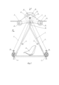
На фиг. 1 изображен канатный велосипед, вид сбоку.Fig. 1 shows a side view of a cable car.
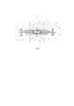
На фиг. 2 изображен вид канатного велосипеда сверху.Fig. 2 shows a view of a cable bike from above.
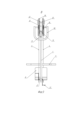
На фиг. 3 изображен вид канатного велосипеда спереди.Fig. 3 shows a front view of a cable bike.
Позициями на чертежах обозначены:The following positions are indicated on the drawings:
1 - рама канатного велосипеда;1 - cable bike frame;
2 - педальный узел;2 - pedal assembly;
3 - звездочка педального узла;3 - pedal assembly sprocket;
4 - цепь;4 - chain;
5 - руль (упор для рук);5 - steering wheel (hand rest);
6 - сиденье;6 - seat;
7 - рама каретки;7 - carriage frame;
8 - ведущее колесо;8 - driving wheel;
9- направляющее колесо;9- guide wheel;
10 - вилка рамы канатного велосипеда;10 - fork of the cable bike frame;
11- трос;11- cable;
12 - тормозной диск;12 - brake disc;
13 - звездочка ведущего колеса;13 - drive wheel sprocket;
14 - ось ведущего колеса 8;14 - axle of the
15 - ось направляющего колеса 9;15 - axis of
16 - шатун кареточного узла 2;16 - connecting rod of the
17 - педаль;17 - pedal;
18 - тормозная машинка.18 - brake machine.
Осуществление и примеры реализации изобретенияImplementation and examples of implementation of the invention
Ниже приведен пример конкретного выполнения заявляемого решения, который не ограничивает варианты его исполнения.Below is an example of a specific implementation of the claimed solution, which does not limit the options for its implementation.
Предлагаемое решение обусловлено тем, что над тросом располагается одно ведущее колесо 8, выполненное из резины со шкивообразным профилем покрышки. По обе стороны от ведущего колеса 8, под тросом размещены направляющие шкивообразные колеса 9, выполненные из полиамида или полиуретана. Все три колеса, размещены на своих осях, расположенных в жесткой раме (корпусе) каретки 7. Ведущее колесо 8 снабжено парой тормозных дисков 12 и парой обгонных муфт со звездочками 13 (фривил), расположенных по обеим сторонам колеса 8, рама 1 канатного велосипеда с сиденьем 6 размещена под кареткой и крепится с помощью вилки 10 на подшипниках (не показаны) к центральной оси ведущего колеса 8.The proposed solution is due to the fact that one
Заявляемое решение, представлено на фиг. 1-3 устраняет основные проблемы известных решений, за счет того, что над тросом 11, в верхней части каретки располагается только одно ведущее колесо 8. Данное колесо 8 является мотор-колесом и оснащено по обеим сторонам от колеса тормозными дисками 12, жестко закрепленным на нем. А также, на оси колеса 8 размещены, по обе стороны, обгонные муфты со звездочками 13 для цепи 4 (фривил). Каждая из звездочек 13 предназначена для передачи момента от ведущей звездочки 3, через цепь 4 в одном из направлений передвижения по тросу 11 (вперед или назад). Под тросом 11, снизу, впереди и сзади размещены два направляющих колеса 9. По одному с каждой стороны относительно ведущего колеса 8.The claimed solution, shown in Fig. 1-3, eliminates the main problems of known solutions, due to the fact that above the
Такая схема позволяет упростить и удешевить конструкцию канатного велосипеда, дополнить ведущее колесо 8 дополнительным движетелем - педальной тяги и дополнительной системой торможения.This design allows to simplify and reduce the cost of the design of the cable bicycle, to supplement the
Каретка заявляемого устройства выполнена из жесткой рамы 7, содержащей две боковые пластины, стянутые между собой шпильками (не показаны). В боковых пластинах рамы 7 размещены три оси, на центральной оси расположено ведущее колесо 8 с резиновой покрышкой шкивообразного профиля. На крайних осях расположены направляющие колеса 9 из полиамида или полиуритана, шкивообразного профиля. Центральное - ведущее колесо 8 расположено на тросу 11, а направляющие колеса 9 под тросом 11. На центральном ведущем колесе 8, с обеих сторон, расположены по одному тормозному диску 12 и звездочка 13 на обгонной муфте (фривил). На центральной оси, по бокам, на подшипниках (не показаны), размещена вилка 10 рамы канатного велосипеда. С обеих сторон рамы 1 канатного велосипеда, выполненной в форме треугольника, в нижних ее углах размещены педальные узлы 2, звездочки 3 на обгонной муфте которых с помощью цепи 4 связаны с соответствующими звездочками 13 ведущего колеса 8. Также, с каждой стороны рамы 1 канатного велосипеда, закреплен руль 5, с рычагом тормоза (не показан), последний, через тросик (не показан), связан с тормозной машинкой 18 установленной над соответствующим тормозным диском 12 ведущего колеса 8. Внутри рамы 1 размещено сиденье 6, с возможностью поворота на 360 градусов в горизонтальной плоскости и механизмом фиксации (не показан), который может представлять собой обычный шпингалет с пружиной, позволяющий осуществлять фиксацию сиденья 6 в одном из выбранных положений, относительно его оси поворота. Сиденье снабжено ремнями безопасности (крепления пассажира). Узел поворота сиденья 6, механизм фиксации и ремни безопасности не показаны на чертежах.The carriage of the claimed device is made of a rigid frame 7 containing two side plates pulled together by studs (not shown). Three axles are placed in the side plates of the frame 7, a
Для возможности движения по тросу 11 колеса 8 и 9 выполнены шкивообразного профиля из полиамида или полиуритана. Они служат исключительно для придания направления канатного велосипеда, строго вдоль оси троса, и также компенсируют момент вращения в вертикальной плоскости, возникающий от момента вращения ведущего колеса 8.To enable movement along the
Крепление поворотного сиденья 6 предпочтительно осуществлять на нижней части рамы 1. Крепление рулей 5 осуществляется на боковых частях рамы 1 в центральных их частях.The
Большая часть деталей канатного велосипеда выполнена с использованием стандартных деталей из велоиндустрии. А именно: педальный узел 2, содержащий ведущую звездочку 3, шатуны 16 и педали 17. Цепь 4 - обычная велосипедная, стандартная цепь, с усилием на разрыв от 1500 кг и более, звездочки на обгонной муфте (фривил) являются велосипедной стандартной деталью. Тормозные диски (толщиной 2 мм) и тормозные машинки с тросиками, ручками торможения и рули, также относятся к обычным велосипедным устройствам и широко известны. Сиденье 6 можно использовать от картинга. Поворотный узел (не показан) сиденья 6 выполняется на базе упорного подшипника размера 95×70×19 мм. Фиксатор (не показан) может быть представлен обычным шпингалетом с пружиной. Рама 1 и вилка 10 канатного велосипеда выполнены из профильной трубы 40×40×2 мм. Корпус каретки 7 выполнен из двух боковых пластин, толщиной 4 мм и стянутых шпильками (не показаны) диаметром 16 мм.Most of the parts of the cable bicycle are made using standard parts from the bicycle industry. Namely:
Ось 14 ведущего колесо 8 и оси 15 направляющих колес 9 выполнены большего диаметра - 15 мм против 10 мм обычного велосипеда. Благодаря наличию шпилек (не показаны), соединяющих боковые пластины рамы каретки 7, исключается сход канатного велосипеда с троса 11, даже в случае разрушения оси 14.The
Вес канатного велосипеда не превышает 25 кг. Если раму и каретку сделать из более легких металлов (алюминий, титан) вес может уменьшится в более чем в два раза при тех же прочностных характеристиках.The weight of a cable bike does not exceed 25 kg. If the frame and carriage are made of lighter metals (aluminum, titanium), the weight can be reduced more than twice with the same strength characteristics.
При необходимости, вместо обычного ведущего колеса 8, расположенного над тросом 11, можно установить мотор колесо. Такие мотор-колеса широко известны, нашли применение на электросамокатах и электровелосипедах. Управление мотор-колесами происходит через специальный контроллер и ручку управления (не показаны на чертежах), расположенную на руле. При этом колесо может приводиться в движение и как за счет электрической тяги, так и за счет педального привода совместно. Также, существуют кареточные моторы (например, фирмы bufang), они могут устанавливаться в месте педального узла 2 и осуществлять тягу на ведущее колесо 8 через цепь 4, при этом допускать и педальную тягу наездника. Управление такими моторами происходит через специальный контролер и ручку управления. Данное оборудование широко известно и может устанавливаться на рамные конструкции и руль 5 соответственно.If necessary, instead of the
Пример реализацииExample of implementation
Канатный велосипед работает следующим образом. Велосипедист размещается на сиденье 6, при этом за счет ручки тормоза (размещена на руле, не показана) удерживает канатный велосипед от перемещения (скатывания) по тросу 11. После пристегивания ремней безопасности (не показаны) размещенных на сиденье 6, отпускается ручка тормоза и канатный велосипед начинает движение по тросу 11 под действием силы тяжести и/или педального и электрических приводов (можно одновременно использовать оба привода). В любой момент, велосипедист за счет тормоза может остановить канатный велосипед и развернув сиденье 6 на 180 градусов, начать движение по тросу 11 в обратном направлении. Такое дублирование - два руля, два педальных привода позволяет существенно повысить надежность канатного велосипеда и самостоятельно добраться до одной из станций в случае поломки одной из систем (например, одна из цепей может порваться, выйти из строя электропривод (мотор-колесо), разрядиться аккумулятор не раскрыты в статике и тд). Практика использования показала, что может быть достигнута скорость канатного велосипеда более 60 км/ч. Обеспечивается комфортная езда при ветрах до 15 м\с. Исключен сход канатного велосипеда с троса 11 при любых ветрах и амплитудах болтанки самого троса 11. Обеспечивается хорошее сцепное свойство ведущего колеса 8 с тросом 11 в дождь. Диаметр троса, при испытаниях, был выбран 16 мм. Благодаря резиновым и полиамидным колесам, нет электрического контакта велосипедиста со стальными элементами силовой конструкции (тросом 11) что предохраняет его от атмосферного электричества.The rope bicycle operates as follows. The cyclist sits on the
Claims (2)
Publications (1)
| Publication Number | Publication Date |
|---|---|
| RU2828503C1 true RU2828503C1 (en) | 2024-10-14 |
Family
ID=
Citations (3)
| Publication number | Priority date | Publication date | Assignee | Title |
|---|---|---|---|---|
| CN201951459U (en) * | 2010-12-31 | 2011-08-31 | 李新民 | Aerial suspension cable bicycle |
| CN208306643U (en) * | 2018-04-24 | 2019-01-01 | 重庆西拓游乐设备股份有限公司 | A kind of aerial bicycle |
| RU2742438C1 (en) * | 2020-08-14 | 2021-02-05 | Константин Владимирович Костенюк | Ropeway carriage |
Patent Citations (3)
| Publication number | Priority date | Publication date | Assignee | Title |
|---|---|---|---|---|
| CN201951459U (en) * | 2010-12-31 | 2011-08-31 | 李新民 | Aerial suspension cable bicycle |
| CN208306643U (en) * | 2018-04-24 | 2019-01-01 | 重庆西拓游乐设备股份有限公司 | A kind of aerial bicycle |
| RU2742438C1 (en) * | 2020-08-14 | 2021-02-05 | Константин Владимирович Костенюк | Ropeway carriage |
Similar Documents
| Publication | Publication Date | Title |
|---|---|---|
| EP2288527B1 (en) | Cable transport system | |
| US5595121A (en) | Amusement ride and self-propelled vehicle therefor | |
| JP2529619B2 (en) | Bicycle stabilizer | |
| US20140116282A1 (en) | Suspended Transport System | |
| US20180370593A1 (en) | Electric Bike | |
| US20240383293A1 (en) | A compact ground vehicle with electric propulsion | |
| KR102517846B1 (en) | Continuous belay system with straight and curved mixture | |
| RU2828503C1 (en) | Kostenyuk's rope bicycle | |
| EP0844957A1 (en) | Semi-rigid, fin-based transportation system | |
| US8689699B2 (en) | Elevated bicycle-based transportation system, connection apparatus for bicycle and modified bicycle | |
| KR102505777B1 (en) | Semi-automatic boarding cart capable of preventing detachment and front-rear shaking | |
| CA2065624C (en) | Blind folks mobile (bfm) | |
| CN202243838U (en) | Human-powered railcar | |
| JP3981966B2 (en) | Parallel motorcycle | |
| CN201863980U (en) | Bicycle by use of pulling, pedaling and recoil | |
| KR200382360Y1 (en) | Mono rail bike | |
| KR20210048009A (en) | 4wheel electric bike | |
| CN214985858U (en) | Mountain road pulley | |
| CN2619848Y (en) | Rail bicycle | |
| RU2742438C1 (en) | Ropeway carriage | |
| US6726231B1 (en) | Vehicle | |
| KR102534843B1 (en) | Eco rider | |
| KR200390239Y1 (en) | Mono rail bike | |
| CN2305226Y (en) | One-wheel game cycle | |
| KR101223421B1 (en) | Recreational hybrid bike |