RU2811155C2 - Automatic feeding device for animals - Google Patents
Automatic feeding device for animals Download PDFInfo
- Publication number
- RU2811155C2 RU2811155C2 RU2022113598A RU2022113598A RU2811155C2 RU 2811155 C2 RU2811155 C2 RU 2811155C2 RU 2022113598 A RU2022113598 A RU 2022113598A RU 2022113598 A RU2022113598 A RU 2022113598A RU 2811155 C2 RU2811155 C2 RU 2811155C2
- Authority
- RU
- Russia
- Prior art keywords
- input
- output
- trigger
- electronic clock
- feed
- Prior art date
Links
- 241001465754 Metazoa Species 0.000 title claims abstract description 21
- 239000000126 substance Substances 0.000 abstract 1
- 241000251468 Actinopterygii Species 0.000 description 3
- 238000009434 installation Methods 0.000 description 2
- 238000003975 animal breeding Methods 0.000 description 1
- 238000010586 diagram Methods 0.000 description 1
- 239000003337 fertilizer Substances 0.000 description 1
- 244000144972 livestock Species 0.000 description 1
- 238000009372 pisciculture Methods 0.000 description 1
Images
Abstract
Description
Изобретение относится к разведению скота и диких животных, рыбоводству, а именно к устройствам для автоматической выдачи дозированной подкормки или корма.The invention relates to livestock and wild animal breeding, fish farming, and in particular to devices for automatically dispensing dosed fertilizer or feed.
Известна кормушка для рыб а.с. СССР 942641, А01К 61/02, 15.07.1982, содержащая бункер для кормов с направляющим кормопроводом, дозатор с рассеивателем кормов, первичный преобразователь наличия рыбы (животного) в зоне действия устройства, блок управления, содержащего исполнительный механизм, открывающий дозатор, причем блок управления дополнительно включает электронные часы, линию задержки, два триггера, два элемента И, семь элементов ИЛИ и электронный ключ.Known fish feeder A.S. USSR 942641, A01K 61/02, 07/15/1982, containing a feed hopper with a feed guide, a dispenser with a feed diffuser, a primary transducer for the presence of fish (animal) in the area of operation of the device, a control unit containing an actuator that opens the dispenser, and the control unit additionally includes an electronic clock, a delay line, two flip-flops, two AND elements, seven OR elements and an electronic key.
Недостатками известного устройства а.с. СССР, А01К 61/02, 15.07.1982 являются сложность и функциональная ограниченность блока управления, что приводит к снижению надежности работы кормушки в целом. Известное устройство реализует три режима работы: самокормление, автоматический и ручной. В режиме самокормления инициатива выдачи корма принадлежит одному из животных при этом отсутствует четкий временной режим кормления и нарушается принцип равного доступа животных к корму. В автоматическом режиме задается четкий временной режим кормления, но не учитывается присутствие животных в зоне устройства и это может приводить к потерям и неэффективному использованию корма. В ручном режиме момент выдачи корма и временной режим кормления осуществляются непосредственно персоналом при этом требуется присутствие обслуживающего персонала в зоне действия устройства, что повышает трудоемкость кормления и снижает экономическую эффективность устройства.The disadvantages of the known device a.s. USSR, A01K 61/02, 07/15/1982 are the complexity and functional limitations of the control unit, which leads to a decrease in the reliability of the feeder as a whole. The known device implements three operating modes: self-feeding, automatic and manual. In the self-feeding mode, the initiative for issuing food belongs to one of the animals, while there is no clear time schedule for feeding and the principle of equal access of animals to food is violated. In automatic mode, a clear time feeding schedule is set, but the presence of animals in the device area is not taken into account and this can lead to losses and inefficient use of feed. In manual mode, the moment of dispensing food and the time mode of feeding are carried out directly by the staff, which requires the presence of service personnel in the operating area of the device, which increases the labor intensity of feeding and reduces the economic efficiency of the device.
Контроль присутствия животных в зоне устройства подкормки наиболее эффективен при кормлении животных в состоянии свободы, например, диких животных, наличие которых в зоне действия кормушки не гарантировано.Controlling the presence of animals in the area of the feeding device is most effective when feeding animals in a state of freedom, for example, wild animals, the presence of which in the area of the feeder is not guaranteed.
Цель изобретения - повышение надежности работы кормушки и улучшение ее эксплуатационных свойств.The purpose of the invention is to increase the reliability of the feeder and improve its performance properties.
Поставленная цель достигается тем, что устройство автоматической подкормки животных, состоящее из бункера для корма с направляющим кормопроводом, дозатора, расположенного под кормопроводом, и оснащенным рассеивателем корма, первичного преобразователя наличия животного в зоне действия устройства, блока управления, содержащего исполнительный механизм, открывающий дозатор, электронные часы, линию задержки, два триггера, элемент ИЛИ, два элемента И, причем первый вход первого элемента И соединен с выходом электронных часов, а выход элемента ИЛИ соединен с первым входом электронных часов, программные часы выход которых подключен ко второму входу электронных часов и к первому входу первого триггера, выход первого триггера подключен к первому входу второго элемента И, выход первичного преобразователя подключен ко второму входу второго элемента И, выход второго элемента И подключен к первому входу второго триггера, первый выход второго триггера подключен ко входу исполнительного механизма и входу линии задержки, а выход линии задержки подключен к первому входу элемента ИЛИ, выход элемента ИЛИ подключен ко второму входу первого триггера, ко второму входу второго триггера и к первому входу электронных часов, второй выход второго триггера подключен ко второму входу первого элемента И, а выход первого элемента И подключен ко второму входу элемента ИЛИ.This goal is achieved by the fact that a device for automatic feeding of animals, consisting of a feed hopper with a feed guide, a dispenser located under the feed line and equipped with a feed diffuser, a primary transducer for the presence of an animal in the operating area of the device, a control unit containing an actuator that opens the dispenser, an electronic clock, a delay line, two flip-flops, an OR element, two AND elements, wherein the first input of the first AND element is connected to the output of the electronic clock, and the output of the OR element is connected to the first input of the electronic clock, the program clock output of which is connected to the second input of the electronic clock and to the first input of the first trigger, the output of the first trigger is connected to the first input of the second AND element, the output of the primary converter is connected to the second input of the second AND element, the output of the second AND element is connected to the first input of the second trigger, the first output of the second trigger is connected to the input of the actuator and the input delay line, and the output of the delay line is connected to the first input of the OR element, the output of the OR element is connected to the second input of the first trigger, to the second input of the second trigger and to the first input of the electronic clock, the second output of the second trigger is connected to the second input of the first AND element, and the output the first AND element is connected to the second input of the OR element.
Изобретение поясняется чертежом.The invention is illustrated by the drawing.
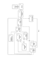
Фиг. 1 Структурная схема устройстваFig. 1 Block diagram of the device
Устройство автоматической подкормки животных состоит из бункера для корма 1 с направляющим кормопроводом, дозатора 2, расположенного под кормопроводом, и оснащенным рассеивателем корма, первичного преобразователя наличия животного в зоне действия устройства 3, блока управления, содержащего исполнительный механизм, воздействующий на дозатор 4, электронные часы 5, линию задержки И, триггеры 8,10, элементы И 6,9, программные часы 12, элемент ИЛИ 7.The device for automatic feeding of animals consists of a
Выход программных часов 12 подключен ко второму входу электронных часов 5 и к первому входу первого триггера 8, выход электронных часов подключен к первому входу первого элемента И 6, выход первого триггера 8 подключен к первому входу второго элемента И 9, выход первичного преобразователя 3 подключен ко второму входу второго элемента И 9, выход второго элемента И 9 подключен к первому входу второго триггера 10. первый выход второго триггера 10 подключен ко входу исполнительного механизма 4 и входу линии задержки 11, а выход линии задержки 11 подключен к первому входу элемента ИЛИ 7, а выход элемента ИЛИ 7 подключен ко второму входу первого триггера 8, ко второму входу второго триггера 10 и к первому входу электронных часов 5, второй выход второго триггера 10 подключен ко второму входу первого элемента И 6, а выход первого элемента И 6 подключен ко второму входу элемента ИЛИ 7, причем выход исполнительного механизма 4 подключен к входу управления дозатором 2, расположенным под кормопроводом, и оснащенным рассеивателем корма, в который поступает корм из бункера для корма 1 с направляющим кормопроводом.The output of the
Работа устройства осуществляется следующим образом.The device operates as follows.
Оператор устанавливает на программных часах 12 заданный режим времени кормления животных. В заданный момент времени выходной сигнал с программных часов 12 поступает на первый вход триггера 8, устанавливая его в положение «1», и на второй вход электронных часов 5, включая отсчет времени ожидания животных в зоне работы кормушки. Если в течении этого времени животное появилось в зоне действия кормушки и сформировался сигнал на выходе первичного преобразователя 3, то на выходе второго элемента И 9 появится сигнал «1», который переведет второй триггер 10 в состояние «1», а сигнал с первого выхода второго триггера 10 включит исполнительный механизм 4 и поступит на линию задержки 11. Исполнительный механизм включает дозатор 2 в который поступает корм из бункера 1. Время работы исполнительного механизма и дозатора ограничивается временем появления сигнала на выходе линии задержки 11. В момент появления сигнала на выходе линии задержки 11 схема ИЛИ 7 формирует сигнал, по которому происходит обнуление электронных часов 5, первого триггера 8 и второго триггера 10.The operator sets the specified animal feeding time mode on
Если в последний момент отсчета времени электронных часов 5 животное появилось в зоне действия кормушки и сформировался сигнал на выходе первичного преобразователя 3, то переключится в состояние «1» второй триггер 10 и сигналом со второго, инверсного выхода второй триггер 10 заблокирует через второй вход первого элемента И 6 прохождение сигнала установки в первоначальное состояние первого 8. второго 10 триггеров и электронных часов 5. Сигнал установки в первоначальное состояние первого 8, второго 10 триггеров и электронных часов 5 поступит через элемент ИЛИ 7 после появления сигнала на выходе линии задержки 11.If at the last moment of counting the time of the
Если в течении времени работы электронных часов 5 животное не появилось в зоне действия кормушки и соответственно не сформировался сигнал на выходе первичного преобразователя 3, то второй триггер 10 останется в состоянии «0» и сигнал с его второго, инверсного выхода разрешит прохождение сигнала с выхода электронных часов 5 через первый вход первого элемента И 6, на второй вход элемента ИЛИ 7, на выходе которого формируется сигнал установки в первоначальное состояние первого 8, второго 10 триггеров и электронных часов 5.If during the operation of the
Изобретение может быть реализовано на известных элементах. Например, бункер 1, дозатор 2 и исполнительное устройство 4 описаны в а.с. СССР 942641, А01К 61/02, 15.07.1982, первичный преобразователь 3 может быть контактным, например, как в а.с. СССР 942641, А01К 61/02, 15.07.1982 для фиксации наличия рыб, так и бесконтактным, например, ультразвуковым, инфракрасным и др. Функции линии задержки 11 может выполнять стандартное реле времени с задержкой на отключение, а функции электронных часов 5 может выполнять стандартное реле времени с задержкой на отключение и с выходным импульсным сигналом. В качестве программных часов 12 может быть использован любой часовой механизм с возможностью программирования времени срабатывания в течении суток, формирующий электрический выходной сигнал в момент срабатывания. Триггеры 8,10, элемент ИЛИ 7, элементы И 6,9 общетехнического исполнения.The invention can be implemented using known elements. For example,
Источники информации, принятые во внимание:Sources of information taken into account:
1. Авторское свидетельство СССР №942641 М. Кл. А0К 61 /02 (прототип);1. Copyright certificate of the USSR No. 942641 M. Kl. A0K 61 /02 (prototype);
2. Патент РФ №2189741 МПК А01К 7/06; А01К 5/02;2. RF Patent No. 2189741
3. Патент РФ №182573 МПК А01К 5/02;3. RF Patent No. 182573
4. Патент GB №2454174, МПК А01К 5/02; А01К 11/00.4. Patent GB No. 2454174, IPC
Claims (1)
Publications (2)
| Publication Number | Publication Date |
|---|---|
| RU2022113598A RU2022113598A (en) | 2023-11-20 |
| RU2811155C2 true RU2811155C2 (en) | 2024-01-11 |
Family
ID=
Citations (6)
| Publication number | Priority date | Publication date | Assignee | Title |
|---|---|---|---|---|
| CH495696A (en) * | 1968-09-09 | 1970-09-15 | Feed Service Corp | Device dispensing a determined quantity of liquid within a determined period of time |
| SU691692A1 (en) * | 1976-11-09 | 1979-10-15 | Предприятие П/Я Г-4132 | Metering control apparatus |
| SU820755A1 (en) * | 1979-11-26 | 1981-04-15 | Всесоюзный Научно-Исследователь-Ский Институт Электрификациисельского Хозяйства | Device for portion feeding of animals |
| SU914008A1 (en) * | 1980-11-04 | 1982-03-23 | Kubansk Selskokhozyajst Inst | Liquid fodder metering-out device |
| SU942641A1 (en) * | 1980-08-13 | 1982-07-15 | Днепропетровский Ордена Трудового Красного Знамени Химико-Технологический Институт Им.Ф.Э.Дзержинского | Feeder for fish |
| DE102012004310A1 (en) * | 2012-02-26 | 2013-08-29 | Fritz Gross | Training device for training animal i.e. cat, in house, has rope fastened to room ceiling, and animation object provided at low end for recording by animal, where animation object is designed as fodder dispenser and toy dispenser |
Patent Citations (6)
| Publication number | Priority date | Publication date | Assignee | Title |
|---|---|---|---|---|
| CH495696A (en) * | 1968-09-09 | 1970-09-15 | Feed Service Corp | Device dispensing a determined quantity of liquid within a determined period of time |
| SU691692A1 (en) * | 1976-11-09 | 1979-10-15 | Предприятие П/Я Г-4132 | Metering control apparatus |
| SU820755A1 (en) * | 1979-11-26 | 1981-04-15 | Всесоюзный Научно-Исследователь-Ский Институт Электрификациисельского Хозяйства | Device for portion feeding of animals |
| SU942641A1 (en) * | 1980-08-13 | 1982-07-15 | Днепропетровский Ордена Трудового Красного Знамени Химико-Технологический Институт Им.Ф.Э.Дзержинского | Feeder for fish |
| SU914008A1 (en) * | 1980-11-04 | 1982-03-23 | Kubansk Selskokhozyajst Inst | Liquid fodder metering-out device |
| DE102012004310A1 (en) * | 2012-02-26 | 2013-08-29 | Fritz Gross | Training device for training animal i.e. cat, in house, has rope fastened to room ceiling, and animation object provided at low end for recording by animal, where animation object is designed as fodder dispenser and toy dispenser |
Similar Documents
| Publication | Publication Date | Title |
|---|---|---|
| US5063880A (en) | Automatic spraying device for farm animals | |
| KR101758886B1 (en) | Smart auto meal providing system with sensor pad | |
| EP3200577A1 (en) | Farm system | |
| WO2003032720A3 (en) | Automatic animal feeder | |
| CN109006528A (en) | A kind of live pig automatic fine feeding device and its control method | |
| RU2811155C2 (en) | Automatic feeding device for animals | |
| CN201274706Y (en) | Automatic batch feeder for fishing | |
| CN208001836U (en) | A kind of storage herds water fountain | |
| CN203444599U (en) | Monitoring system having function of automatically driving pets | |
| CN201107962Y (en) | Sow feeders | |
| WO2020173509A3 (en) | Water drinking device for pets | |
| Leneman et al. | Cost of reducing nitrogen and phosphorus emissions on pig farms in the Netherlands | |
| US20140345533A1 (en) | Sensor controlled food and water bowls for pets | |
| CN104872042A (en) | Infrared triggered type fish independent feeding system and feeding method | |
| CN103371108A (en) | Multifunctional animal feeding trough | |
| Bakirov et al. | Justification of parameters of automatic control system of robot feed distribution in cattle barn | |
| CN205284562U (en) | Automatic device of puting in of granule material | |
| CN213095533U (en) | Feed supply device for livestock breeding | |
| RU2022113598A (en) | Automatic feeding device for animals | |
| CN205389907U (en) | Intelligent control's pet feeder | |
| CN113448274B (en) | Precise feeding method, device, equipment and readable storage medium | |
| SE0202640L (en) | Livestock Feeding Device | |
| CN201107961Y (en) | Feeders for pig | |
| JP4102688B2 (en) | Livestock movement training system | |
| Goonewardene et al. | Residual metabolizable energy intake and its association with diet and test duration |