RU2784005C1 - Method for recursive filtering of a video signal based on a "ring" cmos photodetector - Google Patents
Method for recursive filtering of a video signal based on a "ring" cmos photodetector Download PDFInfo
- Publication number
- RU2784005C1 RU2784005C1 RU2022102689A RU2022102689A RU2784005C1 RU 2784005 C1 RU2784005 C1 RU 2784005C1 RU 2022102689 A RU2022102689 A RU 2022102689A RU 2022102689 A RU2022102689 A RU 2022102689A RU 2784005 C1 RU2784005 C1 RU 2784005C1
- Authority
- RU
- Russia
- Prior art keywords
- ring
- video signal
- photodetector
- video
- television camera
- Prior art date
Links
- 238000001914 filtration Methods 0.000 title claims abstract description 26
- 230000003111 delayed Effects 0.000 claims abstract description 13
- 238000005516 engineering process Methods 0.000 claims abstract description 13
- 238000009825 accumulation Methods 0.000 claims abstract description 10
- 230000015572 biosynthetic process Effects 0.000 claims abstract description 8
- 238000005755 formation reaction Methods 0.000 claims abstract description 8
- 230000000295 complement Effects 0.000 claims abstract description 3
- 239000004065 semiconductor Substances 0.000 claims abstract description 3
- 230000004907 flux Effects 0.000 claims description 2
- 230000000694 effects Effects 0.000 abstract description 4
- 230000035945 sensitivity Effects 0.000 abstract description 4
- 239000000126 substance Substances 0.000 abstract 1
- 239000000203 mixture Substances 0.000 description 7
- 238000004891 communication Methods 0.000 description 6
- 238000010586 diagram Methods 0.000 description 5
- 230000005540 biological transmission Effects 0.000 description 4
- 230000000875 corresponding Effects 0.000 description 4
- 230000001276 controlling effect Effects 0.000 description 3
- 210000004544 DC2 Anatomy 0.000 description 2
- 238000006243 chemical reaction Methods 0.000 description 2
- 238000004590 computer program Methods 0.000 description 2
- 230000002530 ischemic preconditioning Effects 0.000 description 2
- 239000011159 matrix material Substances 0.000 description 2
- 230000036849 Clc Effects 0.000 description 1
- 230000003321 amplification Effects 0.000 description 1
- 230000000903 blocking Effects 0.000 description 1
- 239000002131 composite material Substances 0.000 description 1
- 239000004020 conductor Substances 0.000 description 1
- 238000010276 construction Methods 0.000 description 1
- 230000003247 decreasing Effects 0.000 description 1
- 238000009792 diffusion process Methods 0.000 description 1
- 238000006073 displacement reaction Methods 0.000 description 1
- 238000007667 floating Methods 0.000 description 1
- 238000009432 framing Methods 0.000 description 1
- 238000005286 illumination Methods 0.000 description 1
- 238000004519 manufacturing process Methods 0.000 description 1
- 238000003199 nucleic acid amplification method Methods 0.000 description 1
- 230000003287 optical Effects 0.000 description 1
- 239000007787 solid Substances 0.000 description 1
- 230000003068 static Effects 0.000 description 1
Images


Abstract
Description
Предлагаемое изобретение относится к телевизионной технике и преимущественно может быть использовано в системах анализа интерферограмм, в которых в качестве датчиков видеосигнала применены цифровые «кольцевые» фотоприемники, изготовленные по технологии комплементарных структур «металл-окисел-полупроводник» (КМОП).The present invention relates to television technology and can be mainly used in systems for analyzing interferograms, in which digital "ring" photodetectors made using the technology of complementary metal-oxide-semiconductor (CMOS) structures are used as video signal sensors.
Наиболее близким по технической сущности к заявляемому изобретению следует считать способ рекурсивной фильтрации видеосигнала [1], заключающийся в том, что в телевизионной камере датчиком видеосигнала является фотоприемник, имеющий форму кругового кольца, изготовленный по технологии приборов с зарядовой связью (ПЗС), содержащий на общем «кольцевом» кристалле последовательно связанные между собой зарядовой связью «кольцевую» мишень, «кольцевой» регистр сдвиги и блок преобразования «заряд - напряжение «(БПЗН), при этом линейки светочувствительных элементов и линейки экранированных от света элементов для этой «кольцевой» мишени расположены вдоль радиальных направлений от воображаемого центра кругового кольца к его внешней периферии, причем площадь светочувствительных элементов и соответственно площадь экранированных элементов на «кольцевой» мишени сенсора от строки к строке различна, увеличиваясь по мере движения к внешней периферии до максимальной величины, не превышающей площадь пиксела «кольцевого» регистра сдвига, при этом период импульсов Tr на управляющем входе БПЗН сенсора, обеспечивающий поэлементный сброс напряжения формируемого видеосигнала, определяется из соотношения:The closest in technical essence to the claimed invention should be considered a method of recursive filtering of the video signal [1], which consists in the fact that in the television camera the video signal sensor is a photodetector having the shape of a circular ring, made using the technology of charge-coupled devices (CCD), containing on a common "ring" crystal connected in series with each other by a charge connection "ring" target, "ring" shift register and a "charge-voltage" conversion unit (BPZN), while the lines of light-sensitive elements and the lines of light-shielded elements for this "ring" target are located along the radial directions from the imaginary center of the circular ring to its outer periphery, and the area of the photosensitive elements and, accordingly, the area of the shielded elements on the “ring” sensor target is different from line to line, increasing as you move towards the outer periphery to a maximum value not exceeding the area of a pixel "ring" shift register, while the period of pulses T r at the control input of the BPZN sensor, which provides element-by-element voltage drop of the generated video signal, is determined from the relation:
![]()
![]()
где Тр - период считывания элемента в фотоприемнике;where T p - the period of reading the element in the photodetector;
nm - коэффициент, целое число, величина которого для текущей строки считывания в фотоприемнике, равна отношению:n m - coefficient, an integer, the value of which for the current line of reading in the photodetector is equal to the ratio:

где Δ1 - площадь светочувствительного элемента для первой строки считывания в фотоприемнике;where Δ 1 - the area of the photosensitive element for the first line of reading in the photodetector;
Δm - площадь светочувствительного элемента для текущей строки считывания в фотоприемнике;Δ m is the area of the photosensitive element for the current reading line in the photodetector;
принудительно реализуют в фотоприемнике «длинное» и «короткое» накопление информационных зарядов в смежных кадрах; формируют на выходе фотоприемника мультиплексный сигнал изображения, формируют на выходе «видео» телевизионной камеры мультиплексный телевизионный сигнал, который транслируют на вход «видео» компьютера, осуществляют в компьютере демультиплексирование видеосигнала путем выполнения в нем задержки входного мультиплексного телевизионного сигнала на кадр и реализации взвешенного суммирования прямого и задержанного видеосигналов за счет дистанционного выбора с компьютера для этой задержанной составляющей видеосигнала оптимальной длительности «короткой» экспозиции «кольцевого» фотоприемника ПЗС в телевизионной камере; выполняют в компьютере электрическое вписывание изображения «кольцевого» кадра в прямоугольный растр компьютерного монитора.forcibly implemented in the photodetector "long" and "short" accumulation of information charges in adjacent frames; a multiplex image signal is formed at the output of the photodetector, a multiplex television signal is formed at the output of the "video" of the television camera, which is transmitted to the input "video" of the computer, the video signal is demultiplexed in the computer by delaying the input multiplex television signal per frame and implementing a weighted direct summation and delayed video signals due to remote selection from the computer for this delayed component of the video signal of the optimal duration of the "short" exposure of the "ring" CCD photodetector in the television camera; perform in the computer electrical inscribing of the image of the "ring" frame in a rectangular raster of the computer monitor.
В прототипе [1] непосредственно в «кольцевом» ПЗС-фотоприемнике, оперируя изображениями интерферограмм оптических изделий в зарядовой форме, полученных путем рекурсивной фильтрации видеосигнала, реализуют усреднение случайных колебаний «кольцевого» объекта контроля, имеющего форму кругового цилиндра или кругового кольца. Для прямой составляющей выходного сигнала изображения типовой интервал накопления фотоприемника максимален и соответствует реакции однозвенного рекурсивного фильтра видеосигнала на его выходе. Регулировка же степени его фильтрации достигается за счет управления временем накопления в сторону уменьшения применительно к задержанной составляющей видеосигнала фотоприемника.In the prototype [1], directly in the “ring” CCD photodetector, operating with images of interferograms of optical products in charge form, obtained by recursive filtering of the video signal, averaging of random oscillations of the “ring” control object, having the shape of a circular cylinder or circular ring, is realized. For the direct component of the output image signal, the typical accumulation interval of the photodetector is maximum and corresponds to the response of a single-link recursive video signal filter at its output. Adjustment of the degree of its filtering is achieved by controlling the accumulation time in the direction of decreasing in relation to the delayed component of the video signal of the photodetector.
Недостатком прототипа [1] является снижение точности реализации операции рекурсивной фильтрации сигнала изображения при пониженной освещенности объекта контроля из-за нехватки чувствительности телевизионной камеры, выполненной на базе фотоприемника ПЗС.The disadvantage of the prototype [1] is the decrease in the accuracy of the implementation of the operation of recursive filtering of the image signal at low illumination of the control object due to the lack of sensitivity of the television camera, made on the basis of the CCD photodetector.
Посмотрим на проблему чувствительности телевизионной камеры системы со стороны последних достижений в технологической реализации самого фотоприемника.Let's look at the problem of sensitivity of the television camera of the system from the side of the latest achievements in the technological implementation of the photodetector itself.
Известно, [см. 2, с. 65], что емкость плавающей диффузионной области - выходного блока современных матричных ПЗС, в котором осуществляется считывание заряда, составляет величину порядка 0,01 пФ. Это соответствует коэффициенту преобразования в 15…25 мкВ напряжения видеосигнала на один электрон зарядового сигнала.It is known [cf. 2, p. 65] that the capacitance of the floating diffusion region - the output unit of modern matrix CCDs, in which the charge is read, is about 0.01 pF. This corresponds to a conversion factor of 15...25 µV of the video signal voltage per one charge signal electron.
В фотоприемнике КМОП [см. там же 2, с. 65] емкость считывания обычно того же порядка, однако применение активного усилителя (докоммутационного усиления) позволяет добиться эквивалентного коэффициента преобразования на порядок больше, чем у ПЗС - до 250 мкВ/е.In a CMOS photodetector [see ibid 2, p. 65] the reading capacitance is usually of the same order, however, the use of an active amplifier (pre-switching amplification) makes it possible to achieve an equivalent conversion coefficient an order of magnitude higher than that of a CCD - up to 250 μV / e.
Задачей изобретения является повышение точности реализации рекурсивной фильтрации путем повышения чувствительности телевизионной камеры за счет применения в ее составе «кольцевого» фотоприемника цифрового типа, выполненного по технологии КМОП, используя коэффициент усиления прибора в качестве параметра регулировки степени фильтрации.The objective of the invention is to improve the accuracy of the implementation of recursive filtering by increasing the sensitivity of the television camera by using in its composition a "ring" digital type photodetector made using CMOS technology, using the gain of the device as a parameter for adjusting the degree of filtering.
При этом гарантируется повышенная степень интеграции самой телевизионной камеры, т.к. технология КМОП потенциально позволяет разместить на общем кристалле и необходимое электронное «обрамление» для фотоприемника.At the same time, an increased degree of integration of the television camera itself is guaranteed, since CMOS technology potentially makes it possible to place on a common chip the necessary electronic "framing" for a photodetector.
Поставленная задача решается тем, что в заявляемом способе рекурсивной фильтрации видеосигнала, заключающемся в том, что в телевизионной камере световой поток от интерференционной картины контролируемого объекта проецируют на мишень «кольцевого» датчика видеосигнала - фотоприемника, принудительно реализуют в фотоприемнике накопление информационных зарядов и формирование в смежных кадрах различных по уровню сигналов изображения с величиной размаха видеосигнала соответственно «максимальный» и «уменьшенный», формируют на выходе фотоприемника мультиплексный сигнал изображения, формируют на выходе «видео» телевизионной камеры мультиплексный телевизионный сигнал, который транслируют на вход «видео» компьютера, осуществляют в компьютере демультиплексирование видеосигнала путем выполнения в нем задержки входного мультиплексного телевизионного сигнала на кадр и реализации взвешенного суммирования прямого и задержанного видеосигналов по методу рекурсивной фильтрации видеосигнала за счет дистанционного выбора с компьютера для этой задержанной составляющей видеосигнала оптимальной величины размаха в телевизионной камере; выполняют в компьютере электрическое вписывание изображения «кольцевого» кадра в прямоугольный растр видеомонитора, но при этом, в отличие от прототипа [1], в качестве датчика видеосигнала в телевизионной камере используют реализованный согласно техническому решению [3] цифровой «кольцевой» фотоприемник, который выполнен на кристалле, изготовленном по технологии КМОП, и содержит на мишени линейки светочувствительных пикселов, расположенных вдоль радиальных направлений от воображаемого центра кругового кольца к его внешней периферии, причем число светочувствительных пикселов в каждой «кольцевой» строке мишени одинаково, а их площадь (Δ) от строки к строке различна, увеличиваясь по мере движения к внешней периферии сенсора, причем мишень сенсора состоит из фотодиодных активных пикселов, каждый из которых имеет усилитель с коэффициентом усиления Km, а также встроенный аналого-цифровой преобразователь (АЦП), обеспечивающий передачу видеосигнала активного пиксела на свою «радиальную» шину видео, при этом все они в совокупности объединяют активные пикселы мишени в «радиальные» столбцы, причем управление АЦП для пикселов, расположенных вдоль каждой «кольцевой» строки сенсора, осуществляется при помощи отдельно взятой «кольцевой» строчной шины, общее количество которых определяет число строк в сенсоре, а количество «радиальных» шин видео - число пикселов в каждой строке сенсора; при этом на общем кристалле фотоприемника размещаются и блоки, выполняющие развертку и формирование выходного напряжения цифрового видеосигнала, а именно: «кольцевой» регистр кадровой развертки, осуществляющий выбор «кольцевой» строки; «кольцевой» коммутатор видеосигналов, содержащий коммутаторы видеосигнала для каждого «радиального» столбца, которые управляются с соответствующего выхода «кольцевого» мультиплексора строчной развертки и обеспечивают передачу видеосигнала на выходе каждой «радиальной» шины видео на «кольцевую» шину видео, выход которой является выходом «Видео» фотоприемника, а изменение коэффициента усиления Кт активного пиксела для каждой текущей «кольцевой» строки сенсора обеспечивает одинаковую величину считывающей апертуры в пределах всего «кольцевого» растра изображения, причем коэффициент усиления Кт активного пиксела для каждой текущей «кольцевой» строки «кольцевого» фотоприемника изменяется по соотношению:The problem is solved by the fact that in the claimed method of recursive filtering of the video signal, which consists in the fact that in the television camera the light flux from the interference pattern of the controlled object is projected onto the target of the "ring" video signal sensor - the photodetector, the accumulation of information charges and the formation in adjacent frames of different levels of image signals with the magnitude of the video signal span, respectively, "maximum" and "reduced", form a multiplex image signal at the output of the photodetector, form a multiplex television signal at the output of the "video" of the television camera, which is broadcast to the input "video" of the computer, is carried out in computer, demultiplexing the video signal by delaying the input multiplex television signal per frame and implementing a weighted summation of the direct and delayed video signals using the method of recursive filtering of the video signal due to the distance ongoing selection from the computer for this delayed component of the video signal of the optimal magnitude of the swing in the television camera; perform in the computer an electrical inscription of the image of the "ring" frame in the rectangular raster of the video monitor, but, unlike the prototype [1], as a video signal sensor in the television camera, a digital "ring" photodetector implemented according to the technical solution [3] is used, which is made on a chip manufactured using CMOS technology and contains lines of light-sensitive pixels on the target, located along the radial directions from the imaginary center of the circular ring to its outer periphery, the number of light-sensitive pixels in each "ring" line of the target being the same, and their area (Δ) from line to line is different, increasing as it moves towards the outer periphery of the sensor, and the sensor target consists of photodiode active pixels, each of which has an amplifier with a gain K m , as well as a built-in analog-to-digital converter (ADC), which provides the transmission of the video signal of the active pixel on your "radial" tire video, while all of them combine the active pixels of the target into "radial" columns, and the ADC control for pixels located along each "ring" line of the sensor is carried out using a single "ring" line bus, the total number of which determines the number of lines in the sensor, and the number of "radial" video buses is the number of pixels in each line of the sensor; at the same time, blocks that perform scanning and generating the output voltage of a digital video signal are also placed on the common crystal of the photodetector, namely: a “ring” vertical scanning register that selects the “ring” line; "ring" video switch containing video switches for each "radial" column, which are controlled from the corresponding output of the "ring" line multiplexer and provide video signal transmission at the output of each "radial" video bus to the "ring" video bus, the output of which is the output "Video" of the photodetector, and changing the gain K t of the active pixel for each current "ring" line of the sensor provides the same value of the reading aperture within the entire "ring" image raster, and the gain K t of the active pixel for each current "ring" line "ring" photodetector varies according to the ratio:
где Aj и At - соответственно светочувствительная площадь активного пиксела для первой и текущей строки считывания в «кольцевом» сенсоре, Km1 - значение коэффициента усиления активного пиксела для первой строки считывания в «кольцевом» сенсоре,where Aj and A t are, respectively, the light-sensitive area of the active pixel for the first and current reading line in the "ring" sensor, K m1 - the value of the active pixel gain for the first reading line in the "ring" sensor,
при этом в качестве регулируемого параметра степени рекурсивной фильтрации в телевизионной камере используют не время накопления информационных зарядов в фотоприемнике, а коэффициент усиления вin this case, as an adjustable parameter of the degree of recursive filtering in a television camera, not the time of accumulation of information charges in the photodetector is used, but the gain in
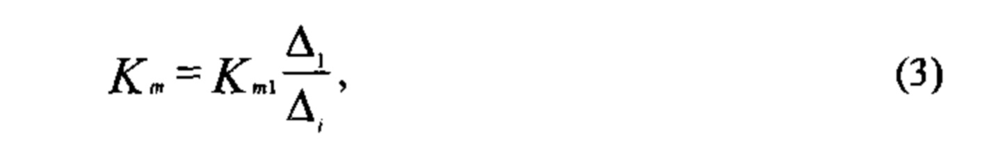
где Δ1 и Δi - соответственно светочувствительная площадь активного пиксела для первой и текущей строки считывания в «кольцевом» сенсоре,where Δ 1 and Δ i are, respectively, the photosensitive area of the active pixel for the first and current reading line in the "ring" sensor,
Km - типовое значение коэффициента усиления активного пиксела, при этом в качестве регулируемого параметра степени рекурсивной фильтрации в телевизионной камере используют не время накопления информационных зарядов в фотоприемнике, а коэффициент усиления задержанном кадре Кm для его активного пиксела, величина которого изменяется в пределах:K m is a typical value of the active pixel gain, while as an adjustable parameter of the degree of recursive filtering in the television camera, not the time of accumulation of information charges in the photodetector is used, but the delayed frame gain K m for its active pixel, the value of which varies within:
![]()
![]()
где ![]()
![]()
Заявляемый способ отличается условием осуществления следующих признаков (действий), а именно:The claimed method is distinguished by the condition for the implementation of the following features (actions), namely:
• принудительной реализацией в «кольцевом» фотоприемнике (сенсоре) накопления информационных зарядов и формирования в смежных кадрах различных по уровню цифровых сигналов изображения за счет регулировки в цифровой форме коэффициента усиления видеосигнала фотоприемника КМОП;• forced implementation in the "ring" photodetector (sensor) of accumulation of information charges and formation in adjacent frames of digital image signals of different levels by digitally adjusting the gain of the video signal of the CMOS photodetector;
• формированием на выходе фотоприемника КМОП цифрового мультиплексного видеосигнала, а на выходе телевизионной камеры - мультиплексного телевизионного сигнала в цифровой форме;• formation of a digital multiplex video signal at the output of a CMOS photodetector, and a multiplex television signal in digital form at the output of a television camera;
• выполнением в компьютере операции демультиплексирования цифрового видеосигнала, которая включает задержку входного мультиплексного путем его записи в оперативную память и взвешенное суммирование прямого и задержанного цифровых видеосигналов по методу рекурсивной фильтрации;• execution of a digital video signal demultiplexing operation in the computer, which includes a delay of the input multiplex signal by writing it to the RAM and a weighted summation of the direct and delayed digital video signals using the recursive filtering method;
• применением в качестве регулируемого параметра степени рекурсивной фильтрации сигнала изображения коэффициента усиления пиксела фотоприемника КМОП в телевизионной камере путем дистанционного управления его показателем с компьютера пользователя;• using as an adjustable parameter the degree of recursive filtering of the image signal of the pixel gain of the CMOS photodetector in the television camera by remotely controlling its indicator from the user's computer;
• выполнением в компьютере электрического вписывания изображения «кольцевого» кадра в прямоугольный растр видеомонитора.• execution in the computer of electrical inscribing of the image of the “ring” frame into the rectangular raster of the video monitor.
Совокупность известных и новых признаков не известна из уровня техники, поэтому заявляемый способ отвечает требованию новизны.The combination of known and new features is not known from the prior art, so the proposed method meets the requirement of novelty.
По техническому результату и методу его достижения предлагаемое решение соответствует критерию о наличии изобретательского уровня.According to the technical result and the method of achieving it, the proposed solution meets the criterion of the presence of an inventive step.
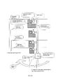
На фиг. 1 изображена структурная схема устройства, реализующего заявляемый способ; на фиг. 2а приведена схемотехническая организация «кольцевого» фотоприемника КМОП; на фиг. 2б - подробности этой организации применительно к отдельно взятому»радиальному» столбцу, на фиг. 3 - пример выполнения электрической схемы коммутатора в составе телевизионной камеры; на фиг. 4 показана функциональная схема устройства платы видео, устанавливаемой, например, в свободный PCI-слот на материнской плате стационарного компьютера; на фиг. 5 показан внешний вид тест-таблицы, которая, как и у прототипа [1], предназначена для оценивания эффекта рекурсивной фильтрации; на фиг. 6 - иллюстрация поставленной задачи по электрическому вписыванию «кольцевого» кадра в прямоугольный растр компьютерного монитора.In FIG. 1 shows a block diagram of a device that implements the proposed method; in fig. 2a shows the circuit organization of the "ring" CMOS photodetector; in fig. 2b - details of this organization in relation to a single "radial" column, in Fig. 3 - an example of the implementation of the electrical circuit of the switch as part of a television camera; in fig. 4 shows a functional diagram of a video card installed, for example, in a free PCI slot on the motherboard of a desktop computer; in fig. 5 shows the appearance of the test table, which, like the prototype [1], is designed to evaluate the effect of recursive filtering; in fig. 6 is an illustration of the task of electrically inscribing a "ring" frame into a rectangular raster of a computer monitor.
Устройство, реализующее предлагаемый способ компьютерной регистрации сигнала изображения интерферограмм на базе матричного фотоприемника КМОП, см. фиг. 1, содержит на передающей стороне телевизионную камеру в позиции 1, состоящую из последовательно расположенных и оптически связанных объектива 1-1 и датчика 1-2 цифрового телевизионного сигнала, а также RS-триггера 1-3, селектора 1-4 синхроимпульсов, счетчика-делителя 1-5, коммутатора 1-6 и цифро-аналогового преобразователя (ЦАП) 1-7; на приемной стороне - компьютер в позиции 2, а между сторонами - линию связи в позиции 3, причем выход «Видео» датчика 1-2, являющийся выходом «Видео» телевизионной камеры, подключен к входу селектора 1-4 синхроимпульсов, выход которого подключен к тактовому входу RS-триггера 1-3 и соответственно к входу последовательно соединенных счетчика-делителя 1-5 и коммутатора 1-6, первый управляющий вход которого, соединенный с первым управляющим входом датчика 1-2, подключен к прямому (Q) выходу RS-триггера 1-3; второй управляющий вход датчика 1-2 подключен к выходу ЦАП 1-7, вход которого подключен к выходу коммутатора 1-6, второй управляющий вход которого, а также S-вход и R-вход RS-триггера 1-3 являются входами «Управление» телевизионной камеры, которые через жилы кабеля линии связи 3 подключены к соответствующим выходам сигналов управления на компьютере 2; а выход цифрового мультиплексного видеосигнала с выхода «Видео» телевизионной камеры транслируется по жилам кабеля линии связи 3 на вход «Видео» компьютера 2.A device that implements the proposed method for computer registration of an image signal of interferograms based on a CMOS matrix photodetector, see Fig. 1, contains on the transmitting side a television camera in
На фиг. 1 позицию 4 занимает тест-таблица, при помощи которой, как и в прототипе [1], может осуществляться проверка работоспособности и тестирование устройства.In FIG. 1 position 4 is occupied by a test table, with the help of which, as in the prototype [1], you can check the performance and test the device.
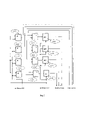
«Кольцевой» фотоприемник 1-2 телевизионной камеры (см. фиг. 2а) выполнен согласно изобретению [3] и содержит на общем кристалле «кольцевую» фотоприемную область (мишень) 1-2-1, «кольцевой» регистр 1-2-2 кадровой развертки, «кольцевой» коммутатор 1-2-3 видеосигналов и «кольцевой» мультиплексор 1-2-4.The "ring" photodetector 1-2 of the television camera (see Fig. 2a) is made according to the invention [3] and contains on a common crystal an "annular" photodetector area (target) 1-2-1, a "ring" register 1-2-2 frame scan, "ring" switch 1-2-3 video signals and "ring" multiplexer 1-2-4.
Как показано на фиг. 2а, активные пикселы на мишени фотоприемника объединены в столбцы, которые расположены вдоль радиальных направлений от воображаемого центра кругового кольца.As shown in FIG. 2a, the active pixels on the photodetector target are combined into columns that are located along the radial directions from the imaginary center of the circular ring.
Каждый активный пиксел мишени (см. фиг. 2б) имеет в своем составе светочувствительную область (площадь) 1-2-1-1, усилитель 1-2-1-2 с коэффициентом усиления Km для каждой текущей «кольцевой» строки и АЦП 1-2-1-3.Each active pixel of the target (see Fig. 2b) includes a photosensitive region (area) 1-2-1-1, an amplifier 1-2-1-2 with a gain K m for each current "ring" row and an ADC 1-2-1-3.
«Кольцевой» коммутатор 1-2-3 видеосигналов состоит из отдельных коммутаторов 1-2-3-1 видеосигнала, число которых соответствует числу активных пикселов в строке, объединенных «кольцевой» шиной видео 1-2-3-2."Ring" video signal switch 1-2-3 consists of separate video signal switches 1-2-3-1, the number of which corresponds to the number of active pixels in a row, united by a "ring" video bus 1-2-3-2.
Отметим, что показанная на фиг. 3 форма светочувствительной площади пиксела в виде прямоугольника, а на фиг. 4 - латинской буквы L - являются условными. На практике электроды зарядового накопления активных пикселов мишени сенсора, совпадающие с площадью их светочувствительной площади, могут быть выполнены совершенно иначе, например, с геометрической формой в виде части кругового кольца.Note that shown in Fig. 3 the shape of the photosensitive area of the pixel in the form of a rectangle, and in FIG. 4 - the Latin letter L - are conditional. In practice, the charge accumulation electrodes of the active pixels of the sensor target, coinciding with the area of their light-sensitive area, can be made in a completely different way, for example, with a geometric shape in the form of a part of a circular ring.
Управление АЦП 1-2-1-3 пиксела, как и всех остальных пикселов мишени, осуществляется с управляющего входа «кольцевого» мультиплексора 1-2-4. передающего сигнал управления с соответствующего выхода «кольцевого» регистра 1-2-2 кадровой развертки.The control of the ADC 1-2-1-3 pixels, as well as all other target pixels, is carried out from the control input of the "ring" multiplexer 1-2-4. transmitting a control signal from the corresponding output of the "ring" register 1-2-2 vertical scan.
Видеосигнал с выхода каждого АЦП 1-2-1-3 для каждого активного пиксела отдельного взятого «радиального» столбца передается на «радиальную» шину видео 1-2-1-5. Далее при помощи «своего» ключевого МОП-транзистора коммутатора 1-2-3-1, управляемого с одного из выходов мультиплексора 1-2-4, цифровой видеосигнал текущего пиксела передается на «кольцевую» шину видео 1-2-3-2, а затем транслируется по ней на выход «кольцевого» фотоприемника.The video signal from the output of each ADC 1-2-1-3 for each active pixel of a single taken "radial" column is transmitted to the "radial" video bus 1-2-1-5. Further, with the help of "its" key MOS transistor of the switch 1-2-3-1, controlled from one of the outputs of the multiplexer 1-2-4, the digital video signal of the current pixel is transmitted to the "ring" video bus 1-2-3-2, and then transmitted through it to the output of the "ring" photodetector.
Отметим, что на фиг. 2а пунктирные стрелки показывают управление «кольцевыми» строчными шинами 1-2-1-4 фотоприемника со стороны «кольцевого» регистра 1-2-2 кадровой развертки. То, что здесь, как и на фиг. 2б, изображены лишь четыре строчные шины - является условностью чертежа. На самом деле число шин 1-2-1-4 соответствует показателю действительного числа «кольцевых» строк в этом сенсоре.Note that in Fig. 2a dotted arrows show the control of the "ring" horizontal tires 1-2-1-4 of the photodetector from the side of the "ring" register 1-2-2 of the frame scan. What is here, as in Fig. 2b, only four horizontal tires are shown - this is a convention of the drawing. In fact, the number of tires 1-2-1-4 corresponds to the actual number of "ring" lines in this sensor.
Поясним дополнительно на фиг. 2а и другое. Стрелки с непрерывными линиями отмечают передачу сигнала изображения в сенсоре по «радиальным» шинам видео 1-2-1-5 в направлении к «кольцевому» коммутатору 1-2-3 видеосигналов.Let us further explain in Fig. 2a and more. Arrows with continuous lines mark the transmission of the image signal in the sensor along the "radial" video buses 1-2-1-5 towards the "ring" switch 1-2-3 video signals.
В результате в «кольцевом» растре последовательно один за другим для каждого пиксела отдельно взятой «кольцевой» строки и последовательно строка за строкой для мишени в целом формируется в цифровом виде напряжение выходного видеосигнала фотоприемника.As a result, in the "ring" raster sequentially one by one for each pixel of a single "ring" line and sequentially line by line for the target as a whole, the voltage of the output video signal of the photodetector is formed in digital form.
Благодаря принятой для изготовления «кольцевого» сенсора видеосигнала технологии КМОП, обеспечивается возможность интегрировать на один общий кристалл не только фотоприемник с АЦП для каждого активного пиксела, но и блоки цифровой развертки телевизионной камеры.Thanks to the CMOS technology adopted for the manufacture of a “ring” video signal sensor, it is possible to integrate not only a photodetector with an ADC for each active pixel, but also digital scanning units of a television camera onto one common chip.
Реализация такого решения обеспечивает существенное снижение общего энергопотребления телевизионной камеры.The implementation of this solution provides a significant reduction in the overall power consumption of the television camera.
Особенностью датчика 1-2 телевизионного сигнала в предлагаемом решении является наличие первого и второго управляющих входов. Если необходимо включить автоматическую регулировку усиления (АРУ) фотоприемника, нужно подать (в уровнях ТТЛ) на первый управляющий вход сигнал логического нуля («0»), а для переключения в режим ручного управления коэффициентом усиления - сигнал логической единицы. («1»).Feature of the sensor 1-2 television signal in the proposed solution is the presence of the first and second control inputs. If it is necessary to enable automatic gain control (AGC) of the photodetector, it is necessary to apply (in TTL levels) to the first control input a logical zero signal (“0”), and to switch to manual gain control mode, a logical one signal. ("one").
Второй управляющий вход датчика 1-2 обеспечивает подачу на фотоприемник (в нашем решении) аналогового сигнала с выхода ЦАП 1-7 в соответствии со значениями, которые приведены ниже в табл. 1.The second control input of the sensor 1-2 provides the photodetector (in our solution) with an analog signal from the output of the DAC 1-7 in accordance with the values given in Table 1 below. one.
Пусть блок 1-7 выполнен по схеме четырехразрядного ЦАП лестничного типа [см. 4, с. 351-353], а величина его входного напряжения UBX составляет 3,75 В.Let block 1-7 be made according to the scheme of a four-bit ladder-type DAC [see. 4, p. 351-353], and the value of its input voltage U BX is 3.75 V.
Тогда переход к каждому следующему двоичному числу из приведенной в табл.1 счетной последовательности на входах приводит к увеличению аналогового выходного сигнала на 0,25 В.Then the transition to each next binary number from the counting sequence shown in Table 1 at the inputs leads to an increase in the analog output signal by 0.25 V.
Входное напряжение ЦАП 1-7 выбрано равным 3,75 не случайно, поскольку эта величина очень близка к выходному напряжению счетчиков и других ИС семейства ТТЛ.The input voltage of the DAC 1-7 was chosen to be 3.75 not by chance, since this value is very close to the output voltage of counters and other ICs of the TTL family.
Следует отметить, что принципиально возможно и желательно не аналоговое управление в датчике 1-2 коэффициентом усиления фотоприемника, а цифровое.It should be noted that it is fundamentally possible and desirable not to analog control in the sensor 1-2 by the gain of the photodetector, but digital.
Тогда задача реализации цифрового управления коэффициентом усиления сенсора становится задачей программиста. Приводимые же здесь данные о показателях соответствующих аналоговых сигналов (см. табл. 1 и табл. 2) конкретизируют возможность ее успешного выполнения.Then the task of implementing digital control of the sensor gain becomes the task of the programmer. The data presented here on the indicators of the corresponding analog signals (see Tables 1 and 2) specify the possibility of its successful implementation.
Напомним, что величина коэффициента усиления Кт активного пиксела для каждой текущей «кольцевой» строки «кольцевого» фотоприемника изменяется по соотношению (3).Recall that the value of the gain K t of the active pixel for each current "ring" line of the "ring" photodetector is changed according to relation (3).

Поэтому расчетные показатели коэффициента усиления «кольцевого» фотоприемника должны быть результатом воздействия его управляющих сигналов (см. табл. 1), учитывая априори изменение Кm в самом сенсоре по площади кадра от первой до последней строки.Therefore, the calculated indicators of the gain of the “ring” photodetector should be the result of the influence of its control signals (see Table 1), taking into account a priori the change in K m in the sensor itself over the frame area from the first to the last line.
В табл. 2, которую следует рассматривать как продолжение табл. 1, «стыкующейся» с ней по вертикали с правой стороны, приведены значения коэффициента Кm «кольцевого» фотоприемника.In table. 2, which should be considered as a continuation of the table. 1, "joining" with it vertically on the right side, the values of the coefficient K m of the "ring" photodetector are given.
Для упрощения построения самой таблицы они ограничены показателями соответственно для первой, второй, предпоследней и последней строки «кольцевого» сенсора, т.к. для промежуточных строк они следуют с той же закономерностью.To simplify the construction of the table itself, they are limited to indicators for the first, second, penultimate and last row of the “ring” sensor, respectively, since for intermediate lines they follow with the same regularity.

Возможная электрическая схема блока 1-6 (см. фиг. 3) содержит первый элемент «И» 1-6-1, второй элемент «И» 1-6-2, третий элемент «И» 1-6-3, четвертый элемент «И» 1-6-4, первый элемент «ИЛИ» 1-6-5, второй элемент «ИЛИ» 1-6-6, третий элемент «ИЛИ» 1-6-7, четвертый элемент «ИЛИ» 1-6-8, первый коммутатор 1-6-9, второй коммутатор 1-6-10, третий коммутатор 1-6-11 и четвертый коммутатор 1-6-12.A possible electrical circuit of the block 1-6 (see Fig. 3) contains the first element "AND" 1-6-1, the second element "AND" 1-6-2, the third element "AND" 1-6-3, the fourth element "AND" 1-6-4, first element "OR" 1-6-5, second element "OR" 1-6-6, third element "OR" 1-6-7, fourth element "OR" 1-6 -8, first switch 1-6-9, second switch 1-6-10, third switch 1-6-11 and fourth switch 1-6-12.
Необходимая кодовая комбинация, определяющая коэффициент усиления видеосигнала фотоприемника телекамеры 1, устанавливается на компьютере 2 и транслируется в ТТЛ-уровнях по линии связи 3 на вторые входы элементов «ИЛИ» 1-6-5, 1-6-6, 1-6-7 и 1-6-8.The necessary code combination that determines the gain of the video signal of the photodetector of the
Этот же двоичный четырехразрядный код на выходе коммутаторов 1-6-9, 1-6-10, 1-6-11 и 1-6-12 является выходом для блока 1-6.The same binary four-bit code at the output of switches 1-6-9, 1-6-10, 1-6-11 and 1-6-12 is the output for block 1-6.
Отметим, что в исходном (начальном) состоянии блока 1-6 на его входе кода присутствует логическая комбинация «0000».Note that in the initial (initial) state of block 1-6, there is a logical combination "0000" at its code input.
Если на входы разрешения коммутаторов 1-6-9, 1-6-10, 1-6-11 и 1-6-12 будет подан низкий логический уровень, тогда, независимо от состояния на входах элементов «И» 1-6-1, 1-6-2, 1-6-3, 1-6-4 и кодовой комбинации на входе, выходы коммутаторов будут изолированы от входов.If a low logic level is applied to the enable inputs of switches 1-6-9, 1-6-10, 1-6-11 and 1-6-12, then, regardless of the state at the inputs of the "AND" elements 1-6-1 , 1-6-2, 1-6-3, 1-6-4 and a code combination at the input, the outputs of the switches will be isolated from the inputs.
RS-триггер 1-3 является тактируемым триггерным устройством RS-типа с высоким активным уровнем на входах управления.RS flip-flop 1-3 is a clocked RS-type flip-flop with active high control inputs.
Селектор 1-4 синхроимпульсов предназначен для выделения из композитного видеосигнала на входе сигнала синхронизации приемника (ССП) с последующим формированием на выходе кадрового синхронизирующего импульса (КСИ).The 1-4 sync selector is designed to isolate the receiver synchronization signal (SSP) from the composite video signal at the input, followed by the formation of a vertical synchronizing pulse (FSI) at the output.
Счетчик-делитель 1-5 предназначен для выполнения деления частоты импульсов КСИ на два.The counter-divider 1-5 is designed to divide the frequency of the KSI pulses by two.
Тест-таблица 4, представленная на фиг. 5, выполнена на бумаге и установлена на вибростенде, обеспечивающем вибрационные смещения в плоскости, параллельной плоскости мишени фотоприемника датчика 1-2.Test table 4 shown in FIG. 5 is made on paper and mounted on a vibration stand that provides vibrational displacements in a plane parallel to the target plane of the sensor 1-2 photodetector.
Таблица 4 содержит расходящиеся в радиальных от центра направлениях черные штрихи, имеющие форму трапеции. Два белых треугольника таблицы являются реперами, позволяющими осуществить оператору настроечную операцию по оптическому вписыванию «кольцевого» теста в компьютерный монитор, имеющий формат экрана 4:3 или 16:9.Table 4 contains black strokes diverging in radial directions from the center, having the shape of a trapezoid. Two white triangles of the table are benchmarks that allow the operator to carry out an adjustment operation to optically fit the "ring" test into a computer monitor with a screen format of 4:3 or 16:9.
На фиг. 4 изображена функциональная схема платы видео, устанавливаемой в свободный PCI-слот на материнской плате стационарного компьютера или в mini PCI-слот ноутбука.In FIG. Figure 4 shows a functional diagram of a video card installed in a free PCI slot on the motherboard of a desktop computer or in a mini PCI slot in a laptop.
При разработке платы видео должно быть выполнено главное и обязательное условие, а именно: она должна быть согласована по каналам ввода/вывода, управлению и питанию с шиной компьютера.When developing a video board, the main and obligatory condition must be met, namely: it must be coordinated in terms of input / output channels, control and power supply with the computer bus.
На вход «Видео» платы поступает цифровой мультиплексный видеосигнал с телевизионной камеры, а на выходе «Видео» платы формируется рекурсивно отфильтрованный цифровой видеосигнал, предназначенный для записи на жесткий диск компьютера.The board's "Video" input receives a digital multiplex video signal from a television camera, and the board's "Video" output generates a recursively filtered digital video signal intended for recording on a computer hard drive.
В нашем примере на плате видео при непосредственном участии компонентов материнской платы и по компьютерной программе реализуются следующие сигнальные операции:In our example, the following signal operations are implemented on the video board with the direct participation of the motherboard components and the computer program:
• Задержка входного цифрового видеосигнала на кадр;• Delay of the input digital video signal per frame;
• Взвешенное суммирование прямого и задержанного видеосигналов;• Weighted summation of direct and delayed video signals;
• Формирование для телевизионной камеры управляющего четырехразрядного двоичного сигнала «Код коэффициента усиления Km;• Formation of a control four-bit binary signal for a television camera “Gain factor code K m ;
• Формирование для телевизионной камеры управляющих однократных импульсов «Пуск» и «Стоп»;• Formation for the television camera of control single impulses "Start" and "Stop";
• Электрическое вписывание «кольцевого» кадра в прямоугольный растр компьютерного монитора.• Electrical inscribing of a "ring" frame into a rectangular raster of a computer monitor.
Все команды для управления телевизионной камерой и для реализации взвешенного суммирования видеосигналов выполняются с клавиатуры компьютера и/или с компьютерной мыши.All commands for controlling the television camera and for implementing the weighted summation of video signals are executed from the computer keyboard and/or from the computer mouse.
Приведенная на фиг. 4 постановка задач по выполнению функциональных действий в ЭВМ, реализуемых программным путем, которые необходимы для осуществления заявляемого способа рекурсивной фильтрации видеосигнала, является, по сути, функциональной схемой платы видео.Shown in FIG. 4, setting tasks for performing functional actions in a computer implemented by software, which are necessary for implementing the proposed method of recursive filtering of a video signal, is, in fact, a functional diagram of a video board.
Отметим, что операция задержки цифрового видеосигнала и операция взвешенного суммирования прямого и задержанного цифровых видеосигналов выполняются на плате видео при условии, когда с компьютера на телевизионную камеру подана команда «Пуск».Note that the digital video delay operation and the weighted summation operation of direct and delayed digital video signals are performed on the video board under the condition that the "Start" command is given from the computer to the television camera.
В исходном состоянии или при возврате телевизионной камеры в исходное состояние командой «Стоп» с компьютера операции задержки и суммирования на плате видео блокируются, а выходным сигналом «Видео» платы становится видеосигнал, поступающий непосредственно с телевизионной камеры.In the initial state or when the television camera is returned to its initial state by the “Stop” command from the computer, the delay and summation operations on the video board are blocked, and the output signal “Video” of the board becomes the video signal coming directly from the television camera.
Заметим, что в компьютерной программе по реализации электрического вписывания «кольцевого» кадра в прямоугольный растр монитора, как и в прототипе [1], должно быть реализовано соблюдение последовательности передачи телевизионных строк, как показано на фиг.6.Note that in the computer program for the implementation of the electrical inscribing of the "ring" frame in the rectangular raster of the monitor, as in the prototype [1], the sequence of transmission of television lines must be implemented, as shown in Fig.6.
Способ рекурсивной фильтрации видеосигнала на базе «кольцевого» фотоприемника КМОП (см. фиг. 1) осуществляется следующим образом.The method of recursive filtering of the video signal based on the "ring" CMOS photodetector (see Fig. 1) is as follows.
Предположим, что расположенная в поле зрения телевизионной камеры 1 интерфенционная картина объекта находится в идеально статическом положении, не испытывая случайных колебаний за счет вибрации и других регулярных механических воздействий низкой частоты. При этом допустим, что внешнее управление для телекамеры отсутствует, т.е. на всех входах «Управление» присутствуют логические «0».Let us assume that the interference pattern of the object located in the field of view of the
Тогда автоматическая регулировка усиления (АРУ) видеосигнала фотоприемника установит распределение коэффициентов усиления активных пикселов сенсора по строкам, представленное в первой (после заголовка) строке табл. 2.Then the automatic gain control (AGC) of the video signal of the photodetector will set the distribution of the gain coefficients of the active pixels of the sensor by rows, presented in the first (after the header) row of Table. 2.
Пусть далее на объекте контроля возникает низкочастотное механическое воздействие. В результате в формируемом видеосигнале неизбежно появляется смаз, а в наблюдаемом с экрана монитора компьютера 2 изображении тест-таблицы 4 заметно снижается его качество.Let further on the object of control there is a low-frequency mechanical action. As a result, a blur inevitably appears in the generated video signal, and in the image of test table 4 observed from the computer monitor 2, its quality noticeably decreases.
Для выполнения задачи изобретения на S-вход RS-триггера 1-3 телевизионной камеры 1 с компьютера 2 подается импульс положительной полярности. В момент совпадения высокого уровня этого импульса с высоким уровнем кадровых синхроимпульсов на его тактовом входе CLC состояние триггера изменяется.To accomplish the task of the invention, a pulse of positive polarity is supplied to the S-input of the RS-trigger 1-3 of the
На прямом выходе (Q) триггера 1-3 устанавливается сигнал логической единицы («1»). Последний подается на первый управляющий вход блока 1-6 и на первый управляющий вход датчика 1-2. Поэтому схема АРУ в датчике 1-2 отключается, а его второй управляющий вход оказывается подключенным к выходу блока 1-6.At the direct output (Q) of the trigger 1-3, a logical one signal (“1”) is set. The latter is fed to the first control input of the block 1-6 and to the first control input of the sensor 1-2. Therefore, the AGC circuit in the sensor 1-2 is turned off, and its second control input is connected to the output of block 1-6.
Отметим, что независимо от этой коммутации селектор 1-4 синхроимпульсов продолжает выделять на выходе кадровые импульсы, а на выходе счетчика-делителя 1-5 формируются импульсы с периодом Тк.Note that regardless of this switching, the sync selector 1-4 continues to emit frame pulses at the output, and pulses with a period T to are formed at the output of the divider counter 1-5.
При этом на время действия низкого уровня меандра импульсов с выхода блока 1-5 на втором управляющем входе датчика 1-2 устанавливается любая логическая комбинация, которая предлагается оператором компьютера для выполнения рекурсивной фильтрации видеосигнала.At the same time, for the duration of the low level of the meander of pulses from the output of block 1-5, any logical combination is set at the second control input of the sensor 1-2, which is proposed by the computer operator to perform recursive filtering of the video signal.
Если, например (см. табл. 1), оператор компьютера подаст в телевизионную камеру код управления «0001», тогда на выходе ЦАП 1-1-7 будет сформирован аналоговый сигнал с уровнем 0,25 В, а коэффициент усиления видеосигнала фотоприемника составит: 0,066Km1 - для первой строки; 0,066Km1 Δ1/Δ2 - для второй строки; соответственно 0,066Km1 Δ1i/Δn-1 - для предпоследней строки и 0,066Km1 Δ1/Δn - для последней строки (см. табл. 2).If, for example (see Table 1), the computer operator sends the control code “0001” to the television camera, then an analog signal with a level of 0.25 V will be generated at the output of DAC 1-1-7, and the gain of the video signal of the photodetector will be: 0.066K m1 - for the first line; 0.066K m1 Δ 1 /Δ 2 - for the second line; respectively 0.066K m1 Δ 1 i/Δ n-1 - for the penultimate row and 0.066K m1 Δ 1 /Δ n - for the last row (see Table 2).
Если же оператор направит управляющий код «0010», тогда величина сигнала на выходе ЦАП 1-7 уже будет 0,50 В, а коэффициент усиления фотоприемника увеличится до уровня 0,133Km1 - для первой строки; 0,133Km1 Δ1/Δ2 - для второй строки; 0,133Km1 Δ1/Δn-1 - для предпоследней строки и 0,133Kml Δ1/Δn - для последней строки соответственно.If the operator sends the control code "0010", then the signal value at the output of the DAC 1-7 will already be 0.50 V, and the gain of the photodetector will increase to the level of 0.133K m1 - for the first line; 0.133K m1 Δ 1 /Δ 2 - for the second line; 0.133K m1 Δ 1 /Δ n-1 - for the penultimate line and 0.133K ml Δ 1 /Δ n - for the last line, respectively.
И так далее, с шагом управляющего сигнала в 0,25 В для пропорционального увеличения величины видеосигнала на выходе.And so on, with a control signal step of 0.25 V to proportionally increase the magnitude of the video signal at the output.
Когда же с выхода блока 1-5 будет подан высокий уровень меандра импульсов, тогда на это время на втором управляющем входе датчика 1-2 установится логическая комбинация «1111», гарантирующая предельно высокие показатели, а именно:When a high level of the pulse meander is applied from the output of block 1-5, then for this time the logical combination “1111” will be set at the second control input of the sensor 1-2, guaranteeing extremely high performance, namely:
коэффициент усиления видеосигнала фотоприемника, равный Km1 - для первой строки; Km1 Δ1/Δ2 - для второй строки; соответственно Km1 Δ1/Δn-1 - для предпоследней строки и Km1 Δ1/Δn - для последней строки (см. нижнюю строку в табл. 2).the gain of the video signal of the photodetector, equal to K m1 - for the first line; K m1 Δ 1 /Δ 2 - for the second line; respectively K m1 Δ 1 /Δ n-1 - for the penultimate line and K m1 Δ 1 /Δ n - for the last line (see the bottom line in Table 2).
В результате завершения фотоэлектрических преобразований датчик 1-2, а, следовательно, и телевизионная камера 1, формируют мультиплексный сигнал изображения.As a result of the completion of photoelectric conversions, the sensor 1-2, and, consequently, the
Далее мультиплексный видеосигнал поступает по линии связи 3 на вход «Видео» платы видео, установленной в разъем расширения на материнской плате компьютера 2.Further, the multiplex video signal arrives via communication line 3 to the “Video” input of the video card installed in the expansion slot on the computer motherboard 2.
Т.к. блокировка снята, плата видео реализует возложенные на нее функции задержки входного видеосигнала и взвешенного суммирования видеосигналов.Because the blocking is removed, the video card implements the functions of delaying the input video signal and weighted summing of video signals assigned to it.
При необходимости возвращения телевизионной камеры в исходный режим работы следует подать с компьютера импульс положительной полярности на вход R-вход RS-триггера 1-3. Тогда состояние триггера изменится, на прямом его выходе (Q) установится сигнал логического «0», а в датчике 1-2 будет восстановлено функционирование схемы АРУ.If it is necessary to return the television camera to its original mode of operation, a positive polarity pulse should be applied from the computer to the R-input of the RS-trigger 1-3. Then the state of the trigger will change, a logical “0” signal will be set at its direct output (Q), and the operation of the AGC circuit will be restored in the sensor 1-2.
Одновременно для платы видео в компьютере будет восстановлено состояние блокировки функций задержки видеосигнала и взвешенного суммирования. Поэтому на выход «Видео» этой платы будет транслироваться цифровой телевизионный сигнал изображения, который повторяет видеосигнал датчика 1-2.At the same time, the video card in the computer will be restored to the video delay and weighted summation lock state. Therefore, the video output of this board will be broadcast a digital television image signal that repeats the video signal of the sensor 1-2.
В заявляемом техническом решении способа рекурсивной фильтрации видеосигнала обеспечивается повышенная точность регистрации интерферограмм путем цифровой регулировки степени самой фильтрации непосредственно в телевизионной камере за счет дистанционного и цифрового управления с компьютера пользователя показателем коэффициента усиления «кольцевого» фотоприемника, выполненного по технологии КМОП.In the claimed technical solution of the method of recursive filtering of the video signal, an increased accuracy of registration of interferograms is provided by digitally adjusting the degree of filtering itself directly in the television camera due to remote and digital control from the user's computer of the gain of the "ring" photodetector made using CMOS technology.
В настоящее время все блоки структурной схемы устройства на фиг. 1, реализующего предлагаемый способ рекурсивной фильтрации видеосигнала на базе «кольцевого» фотоприемника КМОП освоены или могут быть освоены отечественной промышленностью.At present, all blocks of the block diagram of the device in FIG. 1, which implements the proposed method of recursive filtering of a video signal based on a "ring" CMOS photodetector, has been mastered or can be mastered by the domestic industry.
Поэтому следует считать предполагаемое изобретение соответствующим требованию о промышленной применимости.Therefore, the proposed invention should be considered as meeting the requirement of industrial applicability.
ИСТОЧНИКИ ИНФОРМАЦИИSOURCES OF INFORMATION
1. Патент РФ №2639144. МПК H04N 5/225. Способ рекурсивной фильтрации видеосигнала / В.М. Смелков // Б.И. - 2017. - №35.1. RF patent No. 2639144. IPC H04N 5/225. The method of recursive filtering of the video signal / V.M. Smelkov // B.I. - 2017. - No. 35.
2. Березин В.В., Умбиталиев А.А., Фахми Ш.С., Цыцулин А.К. и Шипилов Н.Н. Твердотельная революция в телевидении: Телевизионные системы на основе приборов с зарядовой связью, систем на кристалле и видеосистем на кристалле. Под ред. А.А. Умбиталиева и А.К. Цыцулина. - М.: «Радио и связь», 2006.2. Berezin V.V., Umbitaliev A.A., Fakhmi Sh.S., Tsytsulin A.K. and Shipilov N.N. Solid state television revolution: Charge-coupled device, system-on-a-chip and video-system-on-a-chip television systems. Ed. A.A. Umbitalieva and A.K. Tsytsulina. - M.: "Radio and communication", 2006.
3. Патент РФ №2694742. МПК G06T 11/00, H04N 5/374, H04N 5/335. Способ формирования цифрового видеосигнала на кристалле сенсора, изготовленном по технологии КМОП / В.М. Смелков // Б.И. - 2019. - №20.3. RF patent No. 2694742. IPC G06T 11/00, H04N 5/374, H04N 5/335. The method of forming a digital video signal on a sensor chip made using CMOS technology / V.M. Smelkov // B.I. - 2019. - No. 20.
4. Токхейм Р. Основы цифровой электроники. Перевод с англ. - М.: «Мир», 1988.4. Tokheim R. Fundamentals of digital electronics. Translation from English. - M.: "Mir", 1988.
Claims (3)
Publications (1)
| Publication Number | Publication Date |
|---|---|
| RU2784005C1 true RU2784005C1 (en) | 2022-11-23 |
Family
ID=
Citations (5)
| Publication number | Priority date | Publication date | Assignee | Title |
|---|---|---|---|---|
| US6721008B2 (en) * | 1998-01-22 | 2004-04-13 | Eastman Kodak Company | Integrated CMOS active pixel digital camera |
| US7006704B2 (en) * | 2001-03-23 | 2006-02-28 | Nec Viewtechnology, Ltd. | Method of and apparatus for improving picture quality |
| US7317841B2 (en) * | 2003-12-22 | 2008-01-08 | Ge Medical Systems Global Technology Company, Llc | System and method for image noise reduction using a minimal error spatiotemporal recursive filter |
| US7796153B1 (en) * | 2005-07-08 | 2010-09-14 | Itt Manufacturing Enterprises, Inc. | Equalization system and method for an imaging sensor |
| RU2639144C1 (en) * | 2016-10-04 | 2017-12-20 | Вячеслав Михайлович Смелков | Method of recursive video signal filtering |
Patent Citations (5)
| Publication number | Priority date | Publication date | Assignee | Title |
|---|---|---|---|---|
| US6721008B2 (en) * | 1998-01-22 | 2004-04-13 | Eastman Kodak Company | Integrated CMOS active pixel digital camera |
| US7006704B2 (en) * | 2001-03-23 | 2006-02-28 | Nec Viewtechnology, Ltd. | Method of and apparatus for improving picture quality |
| US7317841B2 (en) * | 2003-12-22 | 2008-01-08 | Ge Medical Systems Global Technology Company, Llc | System and method for image noise reduction using a minimal error spatiotemporal recursive filter |
| US7796153B1 (en) * | 2005-07-08 | 2010-09-14 | Itt Manufacturing Enterprises, Inc. | Equalization system and method for an imaging sensor |
| RU2639144C1 (en) * | 2016-10-04 | 2017-12-20 | Вячеслав Михайлович Смелков | Method of recursive video signal filtering |
Similar Documents
| Publication | Publication Date | Title |
|---|---|---|
| US10847556B2 (en) | Solid-state imaging apparatus and imaging apparatus | |
| US8502895B2 (en) | Variable exposure for color image sensor | |
| JP6668728B2 (en) | Photoelectric conversion element, image reading device, and image forming device | |
| US20230017746A1 (en) | Image acquisition method, electronic device, and non-transitory computerreadable storage medium | |
| US7193199B2 (en) | Solid-state image-sensing device that compensates for brightness at edges of a display area and a driving method thereof | |
| US20150189249A1 (en) | Solid state imaging apparatus and imaging system using the same | |
| EP2320641A2 (en) | Solid-state imaging device, driving method therefor, and imaging apparatus | |
| KR101934695B1 (en) | Image sensor and image capturing apparatus | |
| CN110971799B (en) | Control method, camera assembly and mobile terminal | |
| CN110740272A (en) | Image acquisition method, camera assembly and mobile terminal | |
| US20060181625A1 (en) | CMOS image sensor with wide dynamic range | |
| CN111050041B (en) | Image sensor, control method, camera assembly and mobile terminal | |
| JP5845140B2 (en) | Imaging device and imaging apparatus | |
| KR102046635B1 (en) | Image Sensors, Control Methods, and Electronic Devices | |
| RU2706011C1 (en) | Panoramic television surveillance computer system device | |
| RU2784005C1 (en) | Method for recursive filtering of a video signal based on a "ring" cmos photodetector | |
| US7830438B2 (en) | Frame shuttering scheme for increased frame rate | |
| US4527200A (en) | Solid state imaging device | |
| KR20120122320A (en) | Pixel circuit of image sensor with wide dynamic range and operating method thereof | |
| US6980244B1 (en) | Solid state image pickup device, driving method thereof and camera | |
| RU2784003C1 (en) | Method for computer registration of an image signal of interferograms based on a cmos matrix photodetector | |
| RU2708630C1 (en) | Panoramic television surveillance computer system device | |
| RU2709461C1 (en) | Method of forming a video signal on a sensor chip, made by the technology of a cmos | |
| JP2019033442A (en) | Imaging element and method for controlling the same | |
| RU2639144C1 (en) | Method of recursive video signal filtering |