RU2783503C1 - Device for locking the patch cord connector in the interface jack - Google Patents
Device for locking the patch cord connector in the interface jack Download PDFInfo
- Publication number
- RU2783503C1 RU2783503C1 RU2022119679A RU2022119679A RU2783503C1 RU 2783503 C1 RU2783503 C1 RU 2783503C1 RU 2022119679 A RU2022119679 A RU 2022119679A RU 2022119679 A RU2022119679 A RU 2022119679A RU 2783503 C1 RU2783503 C1 RU 2783503C1
- Authority
- RU
- Russia
- Prior art keywords
- latch
- connector
- housing
- patch cord
- cavity
- Prior art date
Links
- 230000000903 blocking effect Effects 0.000 claims abstract description 27
- 230000013011 mating Effects 0.000 claims abstract description 8
- 230000000694 effects Effects 0.000 abstract 1
- 239000000126 substance Substances 0.000 abstract 1
- 238000007789 sealing Methods 0.000 description 5
- 230000006378 damage Effects 0.000 description 3
- 238000000605 extraction Methods 0.000 description 1
- 238000009434 installation Methods 0.000 description 1
- 238000000926 separation method Methods 0.000 description 1
Images
Abstract
Description
Техническое решение относится к предохранительному устройству для обеспечения контроля авторизованного доступа к сетевым портам коммуникационного оборудования и компьютерной техники в целях обеспечения требований информационной безопасности в информационных системах, телекоммуникационных сетях, на объектах критической информационной инфраструктуры и т.д.The technical solution relates to a safety device for controlling authorized access to network ports of communication equipment and computer equipment in order to ensure information security requirements in information systems, telecommunications networks, at critical information infrastructure facilities, etc.
Из уровня техники известен разъем, содержащий штекер и соответствующее гнездо, закрепленное на передней панели. Штекер во вставленном в гнездо состоянии защищен от извлечения предохранительным элементом, причем предохранительный элемент содержит защелку, которая входит во фронтальный зажим, и, по меньшей мере, одну закрывающую часть. Посредством защелки предохранительный элемент неразъемно соединен с гнездом или передней панелью, при этом закрывающая часть предохранительного элемента закрывает захватный участок штекера или зажимает кабель за захватным участком. Извлекается штекер посредством его захвата за захватные участки. Патент РФ № 2370868, опубликован 20.10.2009.In the prior art, a connector is known that contains a plug and a corresponding socket fixed on the front panel. The plug, when inserted into the socket, is protected from being pulled out by a safety element, wherein the safety element comprises a latch that fits into the front clip and at least one closing part. By means of a latch, the safety element is permanently connected to the socket or the front panel, while the closing part of the safety element closes the gripping area of the plug or clamps the cable behind the gripping area. The plug is removed by grabbing it by the gripping sections. Patent of the Russian Federation No. 2370868, published on 10/20/2009.
Из уровня техники известно решение, выбранное в качестве ближайшего аналога представляющее собой предохранительное приспособление для защелки штекера. Приспособление включает запорное устройство, блокирующее положение защелки в стопорном положении в контакте со штекером. Для приведения в действие элемента деблокировки с последующим разъединением штепсельного соединения, специальный ключ подводится через элемент доступа и проворачивается в определенном направлении. Патент РФ № 2368045, опубликован 20.09.2009.From the prior art, a solution is known, chosen as the closest analogue, which is a safety device for the latch of the plug. The device includes a locking device that locks the position of the latch in the locking position in contact with the plug. To actuate the release element and subsequently disconnect the plug connection, a special key is brought through the access element and rotated in a certain direction. Patent of the Russian Federation No. 2368045, published on September 20, 2009.
Известные устройства характеризуются тем, что коннектор может быть разблокирован и извлечен из порта без каких-либо видимых повреждений.Known devices are characterized in that the connector can be unlocked and removed from the port without any visible damage.
Задачей заявленного решения является создание устройства для блокировки коннектора коммутационного шнура в интерфейсном разъеме, позволяющего осуществить контроль несанкционированного доступа к разъему посредством пломбирования устройства. The objective of the proposed solution is to create a device for blocking the patch cord connector in the interface connector, which allows to control unauthorized access to the connector by sealing the device.
Вместе с тем, заявленное устройство не использует специальный ключ, что не блокирует доступ к сетевому порту и позволяет в экстренной ситуации без особых усилий, инструментов и устройств в короткий промежуток времени снять пломбу и извлечь коннектор. Таким образом в любой аварийной ситуации заявленное решение не несет рисков, связанных с возникновением преграды к отсоединению сетевого кабеля с коннектором от сетевого устройства, например, в случае компьютерной атаки - устройство позволит достаточно быстро разорвать сетевое соединение, при этом факт разрыва будет установлен посредством поврежденной пломбы.At the same time, the claimed device does not use a special key, which does not block access to the network port and allows, in an emergency, without much effort, tools and devices, to remove the seal and remove the connector in a short period of time. Thus, in any emergency, the claimed solution does not bear the risks associated with the emergence of an obstacle to disconnecting the network cable with the connector from the network device, for example, in the event of a computer attack, the device will quickly break the network connection, while the fact of the break will be established by means of a damaged seal .
Технический результат заявляемого решения заключается в возможности блокировки коннектора в разъеме, не допускающей извлечение коннектора без разрушения или нарушения целостности пломбы или контровочной проволоки.The technical result of the proposed solution consists in the possibility of blocking the connector in the connector, which does not allow the connector to be removed without destroying or violating the integrity of the seal or safety wire.
Технический результат заявляемого решения также заключается в точной посадке соединяемых частей устройства и коннектора, в достижении их плотного контакта.The technical result of the proposed solution also lies in the exact fit of the connected parts of the device and the connector, in achieving their tight contact.
Технический результат заявляемого решения также заключается в повышении удобства фиксации устройства для блокировки коннектора и в возможности простого и быстрого извлечения коннектора после разрушения проволоки или пломбы.The technical result of the proposed solution also consists in increasing the convenience of fixing the device for blocking the connector and in the possibility of simple and quick removal of the connector after the destruction of the wire or seal.
Заявленный технический результат достигается за счет того, что устройство для блокировки коннектора коммутационного шнура в интерфейсном разъеме содержит корпус и фиксатор, каждый из которых включает полость для продевания через нее проволоки, корпус включает нижнее основание и перпендикулярные ему вертикальные элементы, выполнен с возможностью размещения и ограничения перемещения коннектора шнура в пространстве между основанием и вертикальными элементами в верхнее и боковые направления относительно основания, при этом с внутренней стороны корпуса на основании выполнен упор, соответствующий выемке коннектора для ограничения перемещения коннектора вперед относительно основания корпуса, фиксатор включает упор, при этом фиксатор выполнен с возможностью размещения в корпусе с сопряжением упора с корпусом с тыльной его стороны и совмещением полостей для продевания через них проволоки, при этом корпус включает ограничитель перемещения фиксатора вверх относительно основания, фиксатор также содержит выступ, размещаемый под защелкой коннектора, и полость для размещения в ней конца защелки, ограниченную сверху, снизу и с боковых сторон.The claimed technical result is achieved due to the fact that the device for blocking the patch cord connector in the interface connector contains a housing and a latch, each of which includes a cavity for threading wire through it, the housing includes a lower base and vertical elements perpendicular to it, is made with the possibility of placement and restriction movement of the cord connector in the space between the base and vertical elements in the upper and lateral directions relative to the base, while on the inside of the body on the base there is a stop corresponding to the notch of the connector to limit the movement of the connector forward relative to the base of the body, the latch includes a stop, while the latch is made with the possibility of placing in the body with the stop mating with the body on its back side and matching the cavities for threading wire through them, while the body includes a limiter for moving the latch upward relative to the base, the latch also with holds a protrusion placed under the latch of the connector, and a cavity for accommodating the end of the latch in it, limited from above, below and from the sides.
Корпус, включающий нижнее основание и перпендикулярные ему боковые вертикальные элементы, выполненный с возможностью ограничения перемещения коннектора шнура в пространстве между основанием и вертикальными элементами в верхнее и боковые направления относительно основания, необходим для размещения в нем коннектора шнура и частичной его фиксации.The housing, including the lower base and side vertical elements perpendicular to it, designed to limit the movement of the cord connector in the space between the base and the vertical elements in the upper and lateral directions relative to the base, is necessary to accommodate the cord connector in it and partially fix it.
Выполненный на основании упор, соответствующий выемке коннектора, необходим для ограничения перемещения корпуса вдоль коннектора в продольном направлении за счет зацепления упора с выступом коннектора, следующим за выемкой. A stop made on the base, corresponding to the recess of the connector, is necessary to limit the movement of the housing along the connector in the longitudinal direction due to the engagement of the stop with the protrusion of the connector following the recess.
Фиксатор необходим для блокировки доступа к защелке коннектора и подпирания защелки к передней стороне корпуса. Поскольку, заявленный корпус с упором позволяет исключить перемещение коннектора по пяти степеням свободы, наличие одного фиксатора достаточно для полной фиксации коннектора в корпусе.The latch is needed to block access to the connector latch and to prop the latch against the front of the chassis. Since the claimed case with a stop allows to exclude the movement of the connector in five degrees of freedom, the presence of one latch is sufficient to completely fix the connector in the case.
Полость/ полости в корпусе и полость/полости в фиксаторе для продевания через них проволоки необходимы для возможности скрепления корпуса и фиксатора проволокой для последующего пломбирования. За счет упора фиксатора, и выполнения фиксатора с возможностью размещения в корпусе с сопряжением упора с корпусом с тыльной его стороны и совмещением полостей для продевания через них проволоки позволяет соединить и зафиксировать фиксатор в корпусе с установленным в нем коннектором. Указанные полости формируют пространство для размещения в нем проволоки, необходимое для возможности соединения фиксатора с корпусом без возможности их рассоединения посредством пропуска проволоки через полость/полости корпуса и полость/полости фиксатора с последующим ее пломбированием.The cavity/cavities in the body and the cavity/cavities in the retainer for threading the wire through them are necessary to be able to fasten the body and the retainer with wire for subsequent sealing. Due to the stop of the latch, and the execution of the latch with the possibility of being placed in the housing with the mating of the stop with the body on its back side and the alignment of the cavities for threading the wire through them, it allows to connect and fix the latch in the housing with the connector installed in it. These cavities form a space for placing the wire in it, which is necessary for the possibility of connecting the retainer to the body without the possibility of their separation by passing the wire through the cavity/cavities of the body and the cavity/cavities of the retainer with its subsequent sealing.
Корпус включает ограничитель перемещения фиксатора вверх относительно основания, исключающий возможность поднятия фиксатора для последующего извлечения коннектора.The housing includes a limiter for the movement of the latch upwards relative to the base, which excludes the possibility of lifting the latch for subsequent extraction of the connector.
Выступ фиксатора, размещаемый под защелкой коннектора, обеспечивает упор для фиксации защелки коннектора в разъеме. Выступ может быть выполнен сужающимся от полости для размещения в ней конца защелки, для более плавного его помещения под защелку и фиксации защелки в естественном положении. The latch tab, located under the connector latch, provides a stop for locking the connector latch in the connector. The protrusion can be made tapering from the cavity to accommodate the end of the latch in it, for smoother placement under the latch and fixing the latch in its natural position.
Полость для размещения в ней конца защелки, ограниченная сверху, снизу и с боковых сторон, необходима для ограничения доступа к защелке. Заявленная полость не позволяет прижать защелку к коннектору и извлечь коннектор из разъема. А, поскольку, прижатие защелки является единственной возможностью изъятия коннектора, он остается заблокированным в разъеме.A cavity for accommodating the end of the latch in it, limited from above, below and from the sides, is necessary to limit access to the latch. The declared cavity does not allow pressing the latch to the connector and removing the connector from the connector. And, since pressing the latch is the only way to remove the connector, it remains locked in the connector.
В предпочтительном варианте, в каждом из вертикальных элементов корпуса во внутреннее его пространство выполнены выступы, способствующие ограничению перемещения коннектора от основания вдоль стенок корпуса. Конструкция корпуса в данном примере осуществления позволяет зафиксировать коннектор, не позволяя ему перемещаться вверх, вниз, в боковые стороны и вперед, т.е., от тыльной стороны корпуса к фронтальной. Предпочтительно элемент, ограничивающий перемещение фиксатора вверх, представляет собой нижнюю часть выступа в вертикальном элементе корпуса, при этом фиксатор включает планки и выполнен с возможностью размещения в корпусе с расположением планок под выступами. Такая конструкция дополнительно обеспечивает точную посадку и уплотнение фиксатора в корпусе с коннектором.In the preferred embodiment, in each of the vertical elements of the housing, protrusions are made into its internal space, which help limit the movement of the connector from the base along the walls of the housing. The design of the housing in this exemplary embodiment allows the connector to be fixed, preventing it from moving up, down, sideways, and forward, i.e., from the back of the housing to the front. Preferably, the element limiting the movement of the latch upwards is the lower part of the protrusion in the vertical element of the housing, while the latch includes straps and is configured to be placed in the housing with the bars located under the protrusions. This design additionally ensures an exact fit and seal of the retainer in the housing with the connector.
Предпочтительно нижняя часть выступа включает нижнюю поверхность, расположенную с передней стороны корпуса, сочлененную со скошенной поверхностью, другой стороной сочлененной с верхней плоской поверхностью, сопрягаемой с планками фиксатора, параллельной основанию, расположенной с задней стороны корпуса, при этом торцевая часть каждой планки фиксатора также выполнена со скошенной поверхностью, соответствующей скошенной поверхности выступа. Такая конструкция выступов и планок также обеспечивает более точную и удобную посадку, исключающую сдвиги фиксатора, и уплотнение фиксатора в корпусе с размещенным в нем коннектором. Preferably, the lower part of the protrusion includes a lower surface located on the front side of the housing, articulated with a beveled surface, the other side is articulated with the upper flat surface, mating with the latch bars, parallel to the base, located on the rear side of the case, while the end part of each latch bar is also made with a beveled surface corresponding to the beveled surface of the protrusion. This design of the lugs and bars also provides a more precise and comfortable fit that eliminates latch shifts, and seals the latch in the housing with the connector placed in it.
В предпочтительном варианте, полости корпуса выполнены в виде отверстий в его вертикальных элементах. Предпочтительно полость фиксатора выполнена в виде паза. Указанное исполнение позволяет создать простую и удобную в эксплуатации конструкции, обеспечивающую возможность продевания проволоки по прямой траектории в пространстве, сформированном отверстиями и пазом. Заявленное исполнение позволяет легко зафиксировать фиксатор с коннектором, и, при необходимости, быстро извлечь коннектор после разрушения проволоки или пломбы.Preferably, the housing cavities are made in the form of holes in its vertical elements. Preferably, the latch cavity is in the form of a groove. This design allows you to create a simple and easy-to-use design that provides the possibility of threading the wire along a straight path in the space formed by holes and a groove. The claimed design makes it easy to fix the latch with the connector, and, if necessary, quickly remove the connector after the destruction of the wire or seal.
Предпочтительно фиксатор содержит дополнительную полость, выполненную с другой стороны фиксатора относительно упоров, позволяющую посредством одной пломбы зафиксировать устройство блокировки с двух сторон, продев проволоку, с одной стороны, через полости корпуса и фиксатора, и с другой стороны, через дополнительную полость фиксатора. Предпочтительно, дополнительная полость выполнена в виде проушины, за счет свой ограниченной формы, позволяющей зафиксировать проволоку, без необходимости ее натяжения.Preferably, the latch contains an additional cavity made on the other side of the latch relative to the stops, which allows fixing the locking device from both sides by means of one seal, passing the wire, on the one hand, through the cavities of the body and the latch, and on the other hand, through the additional cavity of the latch. Preferably, the additional cavity is made in the form of an eye, due to its limited shape, which allows the wire to be fixed without the need for tension.
Для возможности блокировки двух и более коннекторов в линейно расположенных интерфейсных разъемах устройство для блокировки может быть выполнено с корпусом, включающим, по меньшей мере, три вертикальных элемента для размещения между ними, по меньшей мере, двух коннекторов, разделяющих основание на, по меньшей мере, два посадочных места для коннекторов, при этом, элемент, ограничивающий перемещение фиксатора вверх, выполнен между каждой парой соседних вертикальных элементов, и фиксатором, включающем, по меньшей мере, два упора для сопряжения с соответствующими торцевыми поверхностями стенок, по меньшей мере два выступа, размещаемых под защелками коннекторов между соответствующих стенок корпуса, по меньшей мере две полости для размещения в них концов соответствующих защелок коннекторов. В данном исполнении предпочтительно, чтобы полости корпуса были выполнены в виде отверстий в крайних вертикальный элементах, а полость в вертикальном элементе или вертикальных элементах, расположенных между крайними вертикальный элементами выполнены с пазами.In order to be able to block two or more connectors in linearly located interface connectors, the device for blocking can be made with a housing that includes at least three vertical elements for placing at least two connectors between them, dividing the base into at least two seats for connectors, while the element that limits the movement of the latch upwards is made between each pair of adjacent vertical elements, and the latch, including at least two stops for mating with the corresponding end surfaces of the walls, at least two protrusions placed under the latches of the connectors between the respective walls of the housing, at least two cavities for accommodating the ends of the corresponding latches of the connectors. In this version, it is preferable that the housing cavities are made in the form of holes in the extreme vertical elements, and the cavity in the vertical element or vertical elements located between the extreme vertical elements is made with grooves.
Заявляемое техническое решение далее поясняется с помощью фигур, на которых условно представлен один из возможных вариантов исполнения устройства для блокировки коннектора коммутационного шнура в интерфейсном разъемеThe claimed technical solution is further explained with the help of figures, which conditionally show one of the possible versions of the device for blocking the patch cord connector in the interface connector
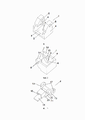
На фиг. 1 представлен общий вид корпуса устройства для блокировки коннектора коммутационного шнура с фронтальной стороны.In FIG. 1 shows a general view of the body of the device for blocking the patch cord connector from the front side.
На фиг. 2 представлен общий вид корпуса устройства для блокировки коннектора коммутационного шнура с тыльной стороны.In FIG. 2 shows a general view of the body of the device for blocking the patch cord connector from the back.
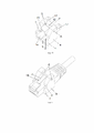
Н фиг. 3 представлен общий вид фиксатора устройства для блокировки коннектора коммутационного шнура.H fig. 3 shows a general view of the locking device for blocking the patch cord connector.
На фиг. 4 представлен общий вид корпуса устройства для блокировки коннектора коммутационного шнура, соединенного с его фиксатором.In FIG. 4 shows a general view of the body of the device for locking the patch cord connector connected to its retainer.
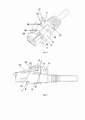
На фиг. 5 представлен общий вид корпуса устройства для блокировки коннектора коммутационного шнура с вставленным в него коннектором.In FIG. 5 shows a general view of the body of the device for blocking the connector of the patch cord with the connector inserted into it.
На фиг. 6 представлен общий вид устройства для блокировки коннектора коммутационного шнура с вставленным в него коннектором.In FIG. 6 shows a general view of the device for blocking the connector of the patch cord with the connector inserted into it.
На фиг. 7 представлен разрез устройства для блокировки коннектора коммутационного шнура с вставленным в него коннектором.In FIG. 7 shows a section of a device for blocking a patch cord connector with a connector inserted into it.
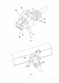
На фиг. 8 представлен общий вид запломбированного устройства для блокировки коннектора коммутационного шнура с вставленным в него коннектором.In FIG. 8 shows a general view of a sealed device for blocking a patch cord connector with a connector inserted into it.
На фиг. 9 представлен общий вид запломбированного устройства для блокировки коннектора коммутационного шнура с вставленным в него коннектором, зафиксированные в интерфейсном разъеме.In FIG. 9 shows a general view of the sealed device for blocking the patch cord connector with the connector inserted into it, fixed in the interface connector.
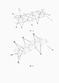
На фиг. 10 представлен общий вид корпуса устройства для блокировки коннектора коммутационного шнура в линейном исполнении.In FIG. 10 shows a general view of the case of the device for blocking the connector of a patch cord in a linear version.
На фиг. 11 представлен общий вид фиксатора устройства для блокировки коннектора коммутационного шнура в линейном исполнении.In FIG. 11 shows a general view of the latch of the device for blocking the patch cord connector in a linear version.
На фигурах 1-11 изображена конструкция заявленного технического решения, цифрами отмечены следующие элементы:Figures 1-11 show the design of the claimed technical solution, the following elements are marked with numbers:
- корпус 1;- building 1;
- фиксатор 2;-
- основание 3 корпуса 1;-
- вертикальный элемент 4 корпуса 1;-
- упор 5 корпуса, соответствующий выемке коннектора;- stop 5 of the body, corresponding to the notch of the connector;
- полость 6 вертикального элемента 4 корпуса 1;-
- выступ 7 вертикального элемента 4;-
- нижняя поверхность 8 выступа 7;- the
- скошенная поверхность 9 выступа 7;- beveled surface 9 of the
- верхняя плоская поверхность 10 выступа 7;- the upper
- планка 11 фиксатора 2;-
- полость 12 фиксатора 2;-
- упор 13 фиксатора 2;- stop 13 of
- торцевая поверхность 14 вертикального элемента 4 корпуса 1;-
- выступ 15 фиксатора 2;-
- полость 16 для свободного конца защелки 18;-
- дополнительная полость 17 фиксатора 2;-
- проволока 19;-
- скошенная поверхность 20 планки 11 фиксатора 2.- beveled
Далее со ссылками на фигуры описана конструкция устройства для блокировки коннектора коммутационного шнура в интерфейсном разъеме.Next, with reference to the figures, the design of the device for blocking the patch cord connector in the interface connector is described.
В качестве коннекторов могут быть использованы коннекторы стандарта RJ 45, RJ-11.RJ 45, RJ-11 standard connectors can be used as connectors.
Устройство для блокировки коннектора коммутационного шнура в интерфейсном разъеме содержит корпус 1 и фиксатор 2.The device for locking the patch cord connector in the interface connector contains a housing 1 and a
Корпус 1 включает нижнее основание 3 и перпендикулярные ему боковые вертикальные элементы 4. Вертикальные элементы могут представлять собой вертикальные стенки, стойки, выступы и т.д. The housing 1 includes a
Корпус 1 выполнен с возможностью размещения и ограничения перемещения коннектора шнура в пространстве, ограниченном основанием 3 и вертикальный элементами 4 в верхнее и боковые направления относительно основания. Предпочтительно в каждом вертикальном элементе 4 корпуса 1 выполнен выступ 7 во внутреннее пространство корпуса 1 для ограничения перемещения коннектора от основания 3 вдоль вертикальных элементов 4 корпуса. The body 1 is made with the possibility of placing and limiting the movement of the cord connector in the space limited by the
Корпус 1 включает ограничитель перемещения фиксатора 2 вверх относительно основания 3. Предпочтительно элемент, ограничивающий перемещение фиксатора 2 вверх представляет собой нижнюю часть выступа 7 в вертикальном элементе 4 корпуса 1, при этом фиксатор включает планки 11 и выполнен с возможностью размещения в корпусе с расположением планок 11 под выступом 7.The housing 1 includes a limiter for the movement of the
В предпочтительном варианте, нижняя часть выступа 7 включает нижнюю поверхность 8, расположенную с передней стороны корпуса 1, сочлененную со скошенной поверхностью 9, другой стороной сочлененной с верхней плоской поверхностью 10, сопрягаемой с планками 11 фиксатора 2, параллельной основанию 3, расположенной с задней стороны корпуса 1, при этом торцевая часть каждой планки 11 фиксатора 2 также выполнена со скошенной поверхностью 20, соответствующей скошенной поверхности 9 выступа 7. In the preferred embodiment, the lower part of the
С внутренней стороны корпуса 1 на основании 3 выполнен упор 5, соответствующий выемке коннектора для ограничения перемещения коннектора относительно основания 3 корпуса 1. Упор 5 может быть выполнен в виде ступеньки или выступа иной формы.On the inside of the body 1 on the
Корпус включает полость 6 для продевания через нее проволоки. Предпочтительно полости 6 корпуса 1 выполнены в виде отверстий в вертикальных элементах 4 корпуса.The housing includes a
Фиксатор 2 также включает полость 12 для продевания через нее проволоки. Предпочтительно, полость 12 фиксатора 2 выполнена в виде паза.The
Форма и глубина полостей 6, 12 не ограничена объемом заявленной формулы, полости 6, 12 могут быть выполнены в виде любых углублений, желобков, проушин и т.д.The shape and depth of the
Фиксатор 2 включает упоры 13, при этом фиксатор 2 выполнен с возможностью размещения в корпусе 1 с сопряжением упора 13 с корпусом 1 с тыльной его стороны, предпочтительно с торцевой поверхностью 14 вертикального элемента 4 корпуса 1, и совмещением полостей 6, 12 для продевания через них проволоки.The
Фиксатор 2 также содержит выступ 15, размещаемый под защелкой 18 коннектора в интерфейсном разъеме, и полость 16 для размещения в ней свободного конца защелки коннектора. Выступ 15 фиксатора 2 предпочтительно выполнен сужающимся от полости16.The
Предпочтительно, фиксатор 2 содержит дополнительную полость 17, выполненную с другой стороны фиксатора 2 относительно упора 13. Дополнительная полость 17 может быть выполнена в виде проушин.Preferably, the
Устройство для блокировки коннектора коммутационного шнура в интерфейсном разъеме может иметь линейный вид исполнения для использования с несколькими блокируемыми коннекторами (фиг. 10,11). При этом, корпус 1 будет включать по меньшей мере три вертикальных элемента 4 для размещения между ними по меньшей мере двух коннекторов, разделяющих основание 3 на, по меньшей мере, два посадочных места для коннекторов, элемент, ограничивающий перемещение фиксатора вверх, выполнен между каждой парой соседних вертикальных элементов 4, фиксатор 2 включает по меньшей мере два упора 13, по меньшей мере два выступа 15, размещаемых под защелками соответствующих коннекторов, и по меньшей мере две полости 16 для размещения в них концов соответствующих защелок. Полости 6 в крайних вертикальных элементах 4 корпуса 1 предпочтительно выполнены в виде отверстий, а полости 6 в вертикальном элементе 4 или элементах 4, расположенных между крайними вертикальными элементами 4, выполнена в виде паза.The locking device for the patch cord connector in the interface jack can be inlined for use with multiple lockable connectors (FIGS. 10, 11). In this case, the body 1 will include at least three
Устройство для блокировки коннектора коммутационного шнура в интерфейсном разъеме может быть выполнено для блокировки от одного до десяти коннекторов.The device for locking the patch cord connector in the interface jack can be configured to lock from one to ten connectors.
Устройство для блокировки коннектора коммутационного шнура в интерфейсном разъеме может быть использовано следующим образом.The locking device for the patch cord connector in the interface jack can be used as follows.
Коннектор коммутационного шнура или свободный коннектор без шнура (при необходимости блокировки пустого, не используемого порта оборудования) устанавливается с тыльной/задней стороны корпуса 1 до упора.A patch cord connector or a loose connector without a cord (if you need to block an empty, unused equipment port) is installed from the rear / rear side of the case 1 until it stops.
Коннектор, установленный в корпусе 1, вставляется в интерфейсный разъем оборудования до характерного щелчка защелки 18 коннектора, после чего проверяется надежность крепления коннектора в разъеме.The connector installed in the housing 1 is inserted into the interface connector of the equipment until the characteristic click of the
Фиксатор 2 вдоль поверхности коннектора по направляющему пазу, сформированному верхней частью коннектора и выступами 7 корпуса 1 вставляется до упора, размещаясь планками 11 под выступами 7, соединяясь упорами 13 с торцевыми поверхностями 14 стенок 4 с тыльной стороны корпуса 1. При этом, выступ 7 фиксатора 2 входит под защелку 18 коннектора, а свободный конец защелки 18 оказывается в полости 16.The
После установки в полость 6 корпуса 1 и через полости 12 и 17 фиксатора 2 продевается контровочная проволока 19, плотно затягивается любым удобным для соответствующей конструкции способом и фиксируется пломбировочным устройством. Вместо проволоки может быть также использована нить, шнур и тому подобное.After installation in the
Попытка извлечения коннектора из разъема или из заявленного устройства после пломбирования характеризуется невозможностью прижатия или разрушения защелки. Разрушение пломбы, являясь единственным способом извлечения фиксатора с последующим освобождением коннектора, является сдерживающим фактором при попытке несанкционированного доступа. При этом, в случае аварийной ситуации при необходимости извлечения коммутационного шнура, пломба или проволока могут быть легко разрушены, однако, факт разрыва будет очевиден. An attempt to remove the connector from the connector or from the claimed device after sealing is characterized by the impossibility of pressing or destroying the latch. Breaking the seal, being the only way to remove the latch and then release the connector, is a deterrent to unauthorized access. At the same time, in the event of an emergency, if it is necessary to remove the patch cord, the seal or wire can be easily destroyed, however, the fact of the break will be obvious.
В случае необходимости блокировки и контроля ряда близко расположенных коммуникационных портов применяется линейное групповое устройство для блокировки коннектора. В такой ситуации рекомендуется как минимум в два крайних порта (посадочных места) установить коннекторы для надежной фиксации всего устройства по двум точкам.If it is necessary to block and control a number of closely spaced communication ports, a linear group device is used to block the connector. In such a situation, it is recommended to install connectors in at least two extreme ports (seats) to securely fix the entire device at two points.
Заявленное техническое решение может быть использовано для блокировки фиксаторов в интерфейсных разъемах соответствующих стандартов различного оборудования, такого как коммутаторы, компьютеры, контроллеры и иные сетевые устройства.The claimed technical solution can be used to lock the latches in the interface connectors of the corresponding standards of various equipment, such as switches, computers, controllers and other network devices.
Представленные фигуры, описание конструкции и использования устройство для блокировки коннектора коммутационного шнура в интерфейсном разъеме не исчерпывают возможные варианты исполнения и не ограничивают каким-либо образом объем заявляемого технического решения. Возможны иные варианты исполнения в объеме заявляемой формулы.The presented figures, description of the design and use of the device for blocking the patch cord connector in the interface connector do not exhaust the possible versions and do not limit in any way the scope of the proposed technical solution. Other versions are possible within the scope of the claimed formula.
Claims (11)
Publications (1)
| Publication Number | Publication Date |
|---|---|
| RU2783503C1 true RU2783503C1 (en) | 2022-11-14 |
Family
ID=
Cited By (1)
| Publication number | Priority date | Publication date | Assignee | Title |
|---|---|---|---|---|
| RU238842U1 (en) * | 2025-04-22 | 2025-11-13 | Общество с ограниченной ответственностью "Газпром трансгаз Ухта" | DEVICE FOR RESTORING THE LOCKING MECHANISM OF THE 8P8S CONNECTOR |
Citations (6)
| Publication number | Priority date | Publication date | Assignee | Title |
|---|---|---|---|---|
| US5090916A (en) * | 1990-07-11 | 1992-02-25 | Interconnection Informatique | Male connector for telephone and/or data processing communications network |
| US5478252A (en) * | 1993-02-10 | 1995-12-26 | Societe Anonyme Dite: Alcatel Cable Interface | Disconnectable male connector for communications networks |
| RU2368045C1 (en) * | 2005-08-08 | 2009-09-20 | Рейхл Энд Де-Массари Аг | Plug protection device (switch protection) |
| RU2370868C2 (en) * | 2005-04-04 | 2009-10-20 | Адц Гмбх | Socket |
| RU2547454C2 (en) * | 2009-07-25 | 2015-04-10 | Цеденик Инновативе Металль-Унд Кунстштофтехник Гмбх | System for connection of electric conducting paths to polar connectors of mutually connected elements |
| RU2679178C2 (en) * | 2014-07-08 | 2019-02-06 | Ли Кристофер ФРАНКЛИН | Mounting apparatus |
Patent Citations (6)
| Publication number | Priority date | Publication date | Assignee | Title |
|---|---|---|---|---|
| US5090916A (en) * | 1990-07-11 | 1992-02-25 | Interconnection Informatique | Male connector for telephone and/or data processing communications network |
| US5478252A (en) * | 1993-02-10 | 1995-12-26 | Societe Anonyme Dite: Alcatel Cable Interface | Disconnectable male connector for communications networks |
| RU2370868C2 (en) * | 2005-04-04 | 2009-10-20 | Адц Гмбх | Socket |
| RU2368045C1 (en) * | 2005-08-08 | 2009-09-20 | Рейхл Энд Де-Массари Аг | Plug protection device (switch protection) |
| RU2547454C2 (en) * | 2009-07-25 | 2015-04-10 | Цеденик Инновативе Металль-Унд Кунстштофтехник Гмбх | System for connection of electric conducting paths to polar connectors of mutually connected elements |
| RU2679178C2 (en) * | 2014-07-08 | 2019-02-06 | Ли Кристофер ФРАНКЛИН | Mounting apparatus |
Cited By (1)
| Publication number | Priority date | Publication date | Assignee | Title |
|---|---|---|---|---|
| RU238842U1 (en) * | 2025-04-22 | 2025-11-13 | Общество с ограниченной ответственностью "Газпром трансгаз Ухта" | DEVICE FOR RESTORING THE LOCKING MECHANISM OF THE 8P8S CONNECTOR |
Similar Documents
| Publication | Publication Date | Title |
|---|---|---|
| CN102934292B (en) | Cable tamper prevention | |
| US8025514B1 (en) | Shroud to prevent manipulation of a release mechanism of a plug | |
| US7632125B2 (en) | Plug locking assembly | |
| US7509015B2 (en) | Secure fiber optic network cassette assembly | |
| US4647726A (en) | Telephone security clamp | |
| US8287191B2 (en) | Locking optical and/or electrical connectors and cable assemblies | |
| CN102057540B (en) | Wiring adapter/terminal assembly and corresponding wiring adapter and terminal | |
| CN106469882B (en) | Connector system with disconnect-proven connector position assurance feature | |
| US11139605B2 (en) | Plug connector with latch hooks | |
| KR102067747B1 (en) | A locking apparatus for lan cable | |
| RU2370868C2 (en) | Socket | |
| KR101621454B1 (en) | Locking unit of LAN and locking device comprising the same | |
| KR101925837B1 (en) | LAN port locking device which is easy to install | |
| RU2783503C1 (en) | Device for locking the patch cord connector in the interface jack | |
| JP2006164674A (en) | Incorrect connection preventive cap | |
| US7384282B2 (en) | Lock assembly for attachment to a LAN-cable connector | |
| US11522311B1 (en) | Tamper evident port protector | |
| US9726832B2 (en) | Secure SC optical fiber connector and removal tools | |
| RU2368045C1 (en) | Plug protection device (switch protection) | |
| JP4934737B2 (en) | Unauthorized connection prevention cap | |
| KR101746103B1 (en) | An apparatus for rocking network module | |
| IL309803A (en) | Cover | |
| CN1732599A (en) | Plug for electric socket in lighting systems with bus-bars |