RU2777458C1 - Load platform with removable protective cover - Google Patents
Load platform with removable protective cover Download PDFInfo
- Publication number
- RU2777458C1 RU2777458C1 RU2022101711A RU2022101711A RU2777458C1 RU 2777458 C1 RU2777458 C1 RU 2777458C1 RU 2022101711 A RU2022101711 A RU 2022101711A RU 2022101711 A RU2022101711 A RU 2022101711A RU 2777458 C1 RU2777458 C1 RU 2777458C1
- Authority
- RU
- Russia
- Prior art keywords
- cargo
- head
- vertical pivot
- drive sleeve
- pivot pin
- Prior art date
Links
- 230000001681 protective effect Effects 0.000 title claims abstract description 10
- 239000000126 substance Substances 0.000 abstract description 2
- 230000000694 effects Effects 0.000 abstract 1
- 229910000831 Steel Inorganic materials 0.000 description 1
- 230000002411 adverse Effects 0.000 description 1
- 238000010586 diagram Methods 0.000 description 1
- 238000005516 engineering process Methods 0.000 description 1
- 230000003993 interaction Effects 0.000 description 1
- 239000010959 steel Substances 0.000 description 1
Images
Abstract
Description
Изобретение относится к грузовым контейнерам со съемным кожухом, а именно к конструкции устройства крепления съемного кожуха на раме грузового контейнера.SUBSTANCE: invention relates to cargo containers with a removable casing, namely to the design of a device for attaching a removable casing to the frame of a freight container.
Известна грузовая платформа с защитным кожухом, содержащая грузовую раму для размещения груза, съемный кожух с крышей и стенками для защиты груза, закрепляемый на грузовой раме с помощью фиксирующих устройств, см. RU 202 739, B61D 39/00, B61D 3/16, опубл. 03.03.2021.Known cargo platform with a protective casing containing a cargo frame for placing cargo, a removable casing with a roof and walls to protect the cargo, fixed on the cargo frame with locking devices, see EN 202 739, B61D 39/00, B61D 3/16, publ. . 03.03.2021.
Технической проблемой, свойственной данному устройству, является низкая эффективность фиксирующих устройств, не обеспечивающих надежное закрепление защитного кожуха на грузовой раме.The technical problem inherent in this device is the low efficiency of the locking devices, which do not provide reliable fastening of the protective cover on the cargo frame.
Техническим результатом заявляемого изобретения является увеличение надежности закрепления защитного кожуха на грузовой раме грузовой платформы.The technical result of the claimed invention is to increase the reliability of fixing the protective cover on the cargo frame of the cargo platform.
Заявленный технический результат обеспечивается грузовой платформой со съемным защитным кожухом, содержащей грузовую раму для размещения груза, съемный кожух с крышей и стенками для защиты груза, закрепляемый на грузовой раме с помощью фиксирующих устройств, на съемном кожухе выполнены опорные полки, на которых установлены фиксирующие устройства, фиксирующее устройство выполнено в виде основания с отверстием, закрепленного на опорных полках, в отверстии основания установлен с возможностью поворота вертикальный поворотный палец с направляющей конической головкой диаметром Dгол, на которой на взаимном расстоянии «Н» выполнены две параллельные боковые лыски и упорные торцы, перпендикулярные продольной оси вертикального поворотного пальца, вертикальный поворотный палец содержит приводной хвостовик, на котором выполнены продольные лыски, на хвостовике установлена приводная втулка, для передачи крутящего момента от приводной втулки на вертикальный поворотный палец и при этом для свободного продольного перемещения по вертикальному поворотному пальцу отверстие приводной втулки выполнено с внутренними выступами, контактно взаимодействующими с продольными лысками, для фиксирования вертикального поворотного пальца приводная втулка снабжена упорными радиальными выступами, взаимодействующими с упорами, закрепленными на основании фиксирующего устройства, приводная втулка оснащена рукояткой, для опирания на грузовую раму опорных полок съемного кожуха на грузовой раме выполнены ответные опорные площадки, в каждой из которых соосно соответствующему вертикальному поворотному пальцу выполнен крепежный паз, используемый для пропускания через него направляющих конических головок соответствующих вертикальных поворотных пальцев и фиксирования их путем поворота вертикальных поворотных пальцев и направляющих конических головок с помощью заведения плоских упорных торцов направляющих конических головок под нижнюю поверхность опорных площадок грузовой рамы, указанные пазы выполнены длиной Lотв, большей, чем диаметр Dгол направляющей конической головки, и шириной Sотв, большей, чем расстояние «Н» между параллельными боковыми лысками конических головок, но меньшей, чем диаметр Dгол;The claimed technical result is provided by a cargo platform with a removable protective casing, containing a cargo frame for placing cargo, a removable casing with a roof and walls to protect the cargo, fixed on the cargo frame with locking devices, support shelves are made on the removable casing, on which locking devices are installed, the fixing device is made in the form of a base with a hole fixed on the supporting shelves, in the base hole a vertical rotary pin with a guide conical head with a diameter D head is installed with the possibility of rotation , on which two parallel side flats and thrust ends are made at a mutual distance "H", perpendicular to longitudinal axis of the vertical pivot pin, the vertical pivot pin contains a drive shank on which longitudinal flats are made, a drive sleeve is installed on the shank to transmit torque from the drive sleeve to the vertical pivot pin and at the same time for free longitudinal movement along the vertical pivot pin, the drive sleeve opening is made with internal protrusions that interact with the longitudinal flats; the load frame of the support shelves of the removable casing on the load frame there are reciprocal support platforms, in each of which a mounting groove is made coaxially with the corresponding vertical pivot pin, which is used to pass the guide conical heads of the corresponding vertical pivot pins through it and fix them by turning the vertical pivot pins and the conical guide pins heads by inserting flat thrust ends of the guide conical heads under the lower surface of the supporting platforms of the cargo frame, these grooves are made with a length L otv greater than the diameter D head of the guide conical head, and the width S otv greater than the distance "H" between the parallel side flats of the conical heads, but less than the diameter D goal ;
- опорные полки могут быть размещены в нишах-карманах, выполненных в стенках съемного кожуха;- supporting shelves can be placed in niches-pockets made in the walls of the removable casing;
- упоры, ограничивающие поворот приводной втулки, могут быть выполнены в виде пальца и упорной направляющей пластины, закрепленных на основании фиксирующего устройства;- stops limiting the rotation of the drive sleeve can be made in the form of a pin and a thrust guide plate fixed on the base of the locking device;
- в упорной направляющей пластине и рукоятке приводной втулки могут быть выполнены соосно-совмещаемые сквозные отверстия для размещения в них фиксатора, исключающего поворот приводной поворотной втулки;- in the thrust guide plate and the handle of the drive sleeve, coaxially aligned through holes can be made to accommodate a retainer in them, which excludes the rotation of the drive rotary sleeve;
- на верхнем торце подвижного пальца может быть выполнен упор для фиксирования подвижного пальца в приводной втулке.- on the upper end of the movable pin, a stop can be made to fix the movable pin in the drive sleeve.
Заявляемое изобретение отличается от прототипа тем, что на съемном кожухе выполнены опорные полки, на которых установлены фиксирующие устройства, фиксирующее устройство выполнено в виде основания с отверстием, закрепленного на опорных полках, в отверстии основания установлен с возможностью поворота вертикальный поворотный палец с направляющей конической головкой диаметром Dгол, на которой на взаимном расстоянии «Н» выполнены две параллельные боковые лыски и упорные торцы, перпендикулярные продольной оси вертикального поворотного пальца, вертикальный поворотный палец содержит приводной хвостовик, на котором выполнены продольные лыски, на хвостовике установлена приводная втулка, для передачи крутящего момента от приводной втулки на вертикальный поворотный палец и при этом для свободного продольного перемещения по вертикальному поворотному пальцу отверстие приводной втулки выполнено с внутренними выступами, контактно взаимодействующими с продольными лысками, для фиксирования вертикального поворотного пальца приводная втулка снабжена упорными радиальными выступами, взаимодействующими с упорами, закрепленными на основании фиксирующего устройства, приводная втулка оснащена рукояткой, для опирания на грузовую раму опорных полок съемного кожуха на грузовой раме выполнены ответные опорные площадки, в каждой из которых соосно соответствующему вертикальному поворотному пальцу выполнен крепежный паз, используемый для пропускания через него направляющих конических головок соответствующих вертикальных поворотных пальцев и фиксирования их путем поворота вертикальных поворотных пальцев и направляющих конических головок с помощью заведения плоских упорных торцов направляющих конических головок под нижнюю поверхность опорных площадок грузовой рамы, указанные пазы выполнены длиной Lотв, большей, чем диаметр Dгол направляющей конической головки, и шириной Sотв, большей, чем расстояние «Н» между параллельными боковыми лысками конических головок, но меньшей, чем диаметр Dгол;The claimed invention differs from the prototype in that support shelves are made on the removable casing, on which fixing devices are installed, the fixing device is made in the form of a base with a hole fixed on the support shelves, in the base hole, a vertical rotary pin with a guide conical head with a diameter of D goal , on which two parallel side flats and thrust ends are made at a mutual distance "H", perpendicular to the longitudinal axis of the vertical pivot pin, the vertical pivot pin contains a drive shank on which longitudinal flats are made, a drive sleeve is installed on the shank to transmit torque from the drive sleeve to the vertical pivot pin, and at the same time, for free longitudinal movement along the vertical pivot pin, the opening of the drive sleeve is made with internal protrusions that interact with the longitudinal flats for vertical fixation of the first pivot pin, the drive sleeve is provided with thrust radial protrusions interacting with the stops fixed on the base of the locking device, the drive sleeve is equipped with a handle, to support the supporting shelves of the removable casing on the cargo frame, the response support platforms are made on the cargo frame, each of which is coaxial with the corresponding vertical rotary the pin is provided with a mounting groove used to pass through it the guide conical heads of the corresponding vertical swivel pins and fix them by turning the vertical swivel pins and the guide conical heads by inserting flat thrust ends of the guide conical heads under the lower surface of the support pads of the cargo frame, these grooves are made long L resp greater than the diameter D head of the guide conical head, and the width S resp greater than the distance "H" between the parallel side flats of the conical heads, but less than the diameter D head ;
- опорные полки размещены в нишах-карманах, выполненных в стенках съемного кожуха;- supporting shelves are placed in niches-pockets made in the walls of the removable casing;
- упоры, ограничивающие поворот приводной втулки, выполнены в виде пальца и упорной направляющей пластины, закрепленных на основании фиксирующего устройства;- stops limiting the rotation of the drive sleeve, made in the form of a pin and a thrust guide plate, fixed on the base of the locking device;
- в упорной направляющей пластине и рукоятке приводной втулки выполнены соосно-совмещаемые сквозные отверстия для размещения в них фиксатора, исключающего поворот приводной втулки;- in the thrust guide plate and the handle of the drive sleeve, coaxially aligned through holes are made to accommodate a retainer in them, which excludes the rotation of the drive sleeve;
- на верхнем торце подвижного пальца выполнен упор для фиксирования подвижного пальца в приводной втулке.- on the upper end of the movable pin there is a stop for fixing the movable pin in the drive sleeve.
Такие отличия от прототипа дает основание утверждать о соответствии предлагаемых технического решения критерию патентоспособности изобретения - «новизна». Сравнение предлагаемого устройства не только с прототипом, но и с другими техническими решениями в данной области техники, не позволило выявить в них признаки, аналогичные отличительным признакам предлагаемого технического решения, что позволяет сделать вывод о соответствии условию патентоспособности изобретения - «изобретательский уровень».Such differences from the prototype gives reason to assert that the proposed technical solution meets the criterion of patentability of the invention - "novelty". Comparison of the proposed device not only with the prototype, but also with other technical solutions in this field of technology, did not allow us to identify features in them similar to the distinguishing features of the proposed technical solution, which allows us to conclude that the condition of patentability of the invention - "inventive step" is met.
Изобретение представлено на чертежах, где:The invention is shown in the drawings, where:
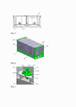
- на Фиг. 1 - грузовая платформа со съемным защитным кожухом, главный вид;- in Fig. 1 - cargo platform with a removable protective cover, main view;
- на Фиг. 2 - то же самое, изометрическая проекция;- in Fig. 2 - the same, isometric projection;
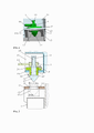
- на Фиг. 3, 4 - выносной элемент «А» с Фиг. 2 при разных положениях рукоятки приводной втулки, изометрическая проекция;- in Fig. 3, 4 - remote element "A" from Fig. 2 at different positions of the drive sleeve handle, isometric view;
- на Фиг. 5 - пример взаимного положения элементов фиксирующего устройства при ориентировании съемного кожуха над грузовой рамой 1, местный вид;- in Fig. 5 - an example of the relative position of the elements of the fixing device when orienting the removable casing over the
- на Фиг. 6, 7 - вид сверху на фиксирующее устройство при различных положениях рукоятки приводной втулки, местный вид;- in Fig. 6, 7 - top view of the locking device at various positions of the drive sleeve handle, local view;
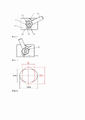
- на Фиг. 8 - схема взаимодействия конической головки с крепежным пазом в опорной площадке грузовой рамы.- in Fig. 8 is a diagram of the interaction of the conical head with the mounting groove in the support area of the cargo frame.
Грузовая платформа содержит грузовую раму 1 (Фиг. 1, 2) для размещения груза, съемный кожух 2 с крышей 2.1 и стенками 2.2 для защиты груза. Съемный кожух 2 закреплен на грузовой раме 1 с помощью фиксирующих устройств 3. На съемном кожухе 2 выполнены опорные полки 2.3 (Фиг. 3, 4, 5), на которых установлены фиксирующие устройства 3. Каждое фиксирующее устройство 3 выполнено в виде основания 3.1 с отверстием 3.2. В отверстии 3.2 установлен с возможностью поворота вертикальный поворотный палец 4 с направляющей конической головкой 4.1 диаметром Dгол. На направляющей конической головке 4.1 на взаимном расстоянии «Н» выполнены две параллельные боковые лыски 4.2 и упорные торцы 4.3, перпендикулярные продольной оси вертикального поворотного пальца 4. Вертикальный поворотный палец 4 содержит приводной хвостовик 4.4, на котором выполнены продольные лыски 4.5. На хвостовике 4.4 установлена приводная втулка 5, предназначенная для передачи крутящего момента от приводной втулки 5 на вертикальный поворотный палец 4 с помощью внутренних выступов 5.1 (Фиг. 6, 7). Приводная втулка 5 оснащена рукояткой 5.3.The cargo platform contains a cargo frame 1 (Fig. 1, 2) for placing cargo, a
Указанные внутренние выступы 5.1 выполнены на взаимном расстоянии, позволяющем свободное продольное перемещение вверх-вниз приводной втулки 5 по параллельным боковым лыскам 4.5 вертикального поворотного пальца 4, при сохранении зацепления между внутренними выступами 5.1 и боковыми лысками 4.5 приводного хвостовика 4.4 вертикального поворотного пальца 4.These internal protrusions 5.1 are made at a mutual distance, allowing free longitudinal movement up and down of the
Для фиксирования вертикального поворотного пальца 4 при закреплении съемного кожуха 2 на грузовой раме 1 приводная втулка 5 снабжена упорными радиальными выступами 5.2, взаимодействующими с упором, выполненным в виде пальца 6, закрепленным на основании 3.1 фиксирующего устройства 3.To fix the vertical
Упор, взаимодействующий с рукояткой 5.3, может быть выполнен в виде упорной направляющей пластины 7, закрепленной на основании 3.1 фиксирующего устройства 3.The stop interacting with the handle 5.3 can be made in the form of a
Для опирания на грузовую раму 1 опорных полок 2.3 съемного кожуха 2 на грузовой раме 1 выполнены ответные опорные площадки 1.1. В каждой из опорных площадок 1.1 соосно соответствующему вертикальному поворотному пальцу 4 выполнен крепежный паз 1.2, предназначенный для пропускания направляющих конических головок 4.1 соответствующих вертикальных поворотных пальцев 4 и фиксирования путем их вместе с направляющими коническими головками 4.1 с помощью заведения плоских упорных торцов 4.3 направляющих конических головок 4.1 за нижнюю поверхность 1.3 опорных площадок 1.1 грузовой рамы 1. Крепежный паз 1.2 (Фиг. 8) выполнен длиной Lотв, большей, чем диаметр Dгол направляющей конической головки 4.1, и шириной Sотв, большей, чем расстояние «Н» между параллельными боковыми лысками конической головки 4.1, но меньшей, чем диаметр Dгол конической головки 4.1.For support on the
Опорные полки 2.3 для размещения на них фиксирующих устройств 3 могут быть размещены в нишах-карманах 2.4, выполненных в стенках 2.2 съемного кожуха 2.Support shelves 2.3 for placing
На верхнем торце подвижного пальца 4 может быть выполнен упор 4.6 для фиксирования подвижного пальца 4 в приводной втулке 5.At the upper end of the
Изобретение используют следующим образом.The invention is used in the following way.
После размещения груза на грузовой раме 1, например, рулонов из стали, бумаги, для защиты груза от внешних неблагоприятных воздействий используют съемный кожух 2.After placing the cargo on the
Съемный кожух 2 с помощью грузоподъемного устройства (не показан) устанавливают на грузовую раму 1, опирая опорные полки 2.3 на опорные площадки 1.1 грузовой рамы 1. Перед этим направляющие конические головки 4.1 всех фиксирующих устройств 3 с помощью рукояток 5.3 выставляют в положение, когда направляющие головки 4.1 могут свободно пройти через соответствующие крепежные пазы 1.2 опорных площадок 1.1. После размещения съемного кожуха 2 на раме 1 и прохода направляющих конических головок 4.1 через крепежные пазы 1.2 производят закрепление съемного кожуха 2 на грузовой раме 1. Для этого приводную втулку 5 поднимают вверх, перемещая ее по параллельным боковым лыскам 4.2 и выводя из зацепления упорный радиальный выступ 5.2 с первым пальцем 6, рукоятку 5.3 - с упорной направляющей 7. За рукоятку 5.3 поворачивают приводную втулку 5 вместе с подвижным пальцем 4 и его направляющей конической головкой 4.1, при этом ее упорные торцы 4.3 заходят под нижнюю поверхность 1.3 опорных площадок 1.1 грузовой рамы 1, жестко соединяя съемный кожух 2 с грузовой рамой 1. Приводную втулку 5 опускают вниз, перемещая ее по параллельным боковым лыскам 4.2, вводя в зацепление упорный радиальный выступ 5.2 со вторым пальцем 6, а рукоятки 5.3 с упорной направляющей 7, исключая тем самым поворот приводной втулки 5 и соединенного с ней подвижного пальца 4 с направляющей головкой 4.1. Аналогично переводят в рабочее положение все фиксирующие устройства 3.
Для снятия съемного кожуха 2 с грузовой рамы 1 фиксаторы 3 освобождают в обратной последовательности.To remove the
Для надежного закрепления съемного кожуха 2 на грузовой раме 1 может быть предусмотрено дополнительное фиксирование рукоятки 5.3. Для этого в рукоятке 5.3 выполняют сквозной отверстие 5.3.1, а в упорной направляющей пластине 7 сквозное отверстие 7.1, которые совмещают соосно при повороте рукоятки 5.3 во время закрепления съемного кожуха 2 на грузовой раме 1. Через указанные совмещенные отверстия пропускают фиксатор, выполненный, например, в виде отрезка тросика с соединяемыми концами, дужку замка, шплинт, проволоку, исключающих поворот рукоятки 5.3 и приводной втулки 5 вместе подвижным пальцем 4 и его направляющей конической головки 4.1.For reliable fastening of the
Таким образом, наличие в конструкции фиксатора 3, приводной втулки 5, зафиксированной от поворота радиальным выступом 5.2, взаимодействующим с пальцем 6, рукоятки 5.3, взаимодействующей с упорной направляющей 7, возможность установки дополнительных фиксаторов в отверстия 5.3.1, 7.1, а также необходимость дополнительного принудительного перемещения приводной втулки 5 по продольным лыскам 4.5 приводного хвостовика 4.4 при использовании фиксатора 3, направлено на увеличение надежности закрепления защитного кожуха 2 на грузовой раме 1.Thus, the presence in the design of the
Claims (5)
Publications (1)
| Publication Number | Publication Date |
|---|---|
| RU2777458C1 true RU2777458C1 (en) | 2022-08-04 |
Family
ID=
Citations (4)
| Publication number | Priority date | Publication date | Assignee | Title |
|---|---|---|---|---|
| CN2536462Y (en) * | 2002-04-23 | 2003-02-19 | 攀钢集团钢城企业总公司铁路设备修造厂 | Rain proof devices |
| ES2673741A1 (en) * | 2016-12-23 | 2018-06-25 | Inersa Ingeniería Energética, S.L. | COVER OF PLATFORMS OF TRANSPORT OF GOODS (Machine-translation by Google Translate, not legally binding) |
| RU196540U1 (en) * | 2019-09-19 | 2020-03-04 | Общество с ограниченной ответственностью "Всесоюзный научно-исследовательский центр транспортных технологий" (ООО "ВНИЦТТ") | CAP TO PROTECT CARGO FROM ATMOSPHERIC SEDIMENTS |
| RU202739U1 (en) * | 2020-09-25 | 2021-03-03 | РЕЙЛ 1520 АйПи ЛТД | PROTECTIVE SHELTER FOR CARGO PLATFORM |
Patent Citations (4)
| Publication number | Priority date | Publication date | Assignee | Title |
|---|---|---|---|---|
| CN2536462Y (en) * | 2002-04-23 | 2003-02-19 | 攀钢集团钢城企业总公司铁路设备修造厂 | Rain proof devices |
| ES2673741A1 (en) * | 2016-12-23 | 2018-06-25 | Inersa Ingeniería Energética, S.L. | COVER OF PLATFORMS OF TRANSPORT OF GOODS (Machine-translation by Google Translate, not legally binding) |
| RU196540U1 (en) * | 2019-09-19 | 2020-03-04 | Общество с ограниченной ответственностью "Всесоюзный научно-исследовательский центр транспортных технологий" (ООО "ВНИЦТТ") | CAP TO PROTECT CARGO FROM ATMOSPHERIC SEDIMENTS |
| RU202739U1 (en) * | 2020-09-25 | 2021-03-03 | РЕЙЛ 1520 АйПи ЛТД | PROTECTIVE SHELTER FOR CARGO PLATFORM |
Similar Documents
| Publication | Publication Date | Title |
|---|---|---|
| US4884831A (en) | Auxiliary door lock for a powered garage door | |
| EP2758275B1 (en) | Bicycle fork securing device | |
| US9109409B2 (en) | Safety latch lock | |
| US7988391B2 (en) | Self-locking, overrideable and attenuating cargo guide and restraint | |
| US6749392B1 (en) | Quick connect/disconnect tank lifting brace and method of use | |
| EP0120047A1 (en) | Releasable locking, coupling or support device. | |
| NL8501175A (en) | PORTABLE BEAM CLAMP. | |
| RU2777458C1 (en) | Load platform with removable protective cover | |
| US7490874B2 (en) | Lock device for foldable electronic apparatus | |
| US20190312366A1 (en) | Catenary grounding device fall restriction apparatus and method of use | |
| US12377770B2 (en) | Anti-rollout assemblies and systems for cargo handling system | |
| CN112302424B (en) | Protection method for protection structure and protection method for safekeeping cabinet | |
| US20230217622A1 (en) | Latch assembly and electronic device using same | |
| US10702904B2 (en) | Deck leverage anchor with spaced-apart body portions | |
| US6763768B2 (en) | Ramp latching mechanism | |
| CN210714156U (en) | Lock and equipment with lock | |
| RU2702327C1 (en) | Covered car with fully open side | |
| RU201907U1 (en) | CONTAINER FIXING DEVICE | |
| US8721240B1 (en) | Cargo bracing device | |
| US20050073161A1 (en) | Collapsible grappling hook | |
| CA1312641C (en) | Plate lifting clamp | |
| US6595731B1 (en) | Device for a loading deck | |
| US6883274B2 (en) | Device and method for opening a door | |
| KR100638082B1 (en) | Load floor latch | |
| RU2230008C2 (en) | Fastener for spacecraft placed in orbit |