RU2773503C1 - Device for preventive control of autonomous electric power system - Google Patents
Device for preventive control of autonomous electric power system Download PDFInfo
- Publication number
- RU2773503C1 RU2773503C1 RU2022102735A RU2022102735A RU2773503C1 RU 2773503 C1 RU2773503 C1 RU 2773503C1 RU 2022102735 A RU2022102735 A RU 2022102735A RU 2022102735 A RU2022102735 A RU 2022102735A RU 2773503 C1 RU2773503 C1 RU 2773503C1
- Authority
- RU
- Russia
- Prior art keywords
- load
- logical
- output
- input
- block
- Prior art date
Links
- 230000003449 preventive effect Effects 0.000 title claims abstract description 17
- 230000000903 blocking effect Effects 0.000 claims abstract description 19
- 230000007423 decrease Effects 0.000 claims description 28
- 230000015572 biosynthetic process Effects 0.000 claims description 17
- 230000009467 reduction Effects 0.000 claims description 8
- 238000012544 monitoring process Methods 0.000 claims description 5
- 230000007257 malfunction Effects 0.000 abstract description 9
- 230000008859 change Effects 0.000 abstract description 5
- 238000004870 electrical engineering Methods 0.000 abstract description 3
- 230000007274 generation of a signal involved in cell-cell signaling Effects 0.000 abstract description 3
- 238000001514 detection method Methods 0.000 abstract description 2
- 230000000694 effects Effects 0.000 abstract 2
- 239000000126 substance Substances 0.000 abstract 1
- 239000000446 fuel Substances 0.000 description 8
- 238000000034 method Methods 0.000 description 7
- 230000007704 transition Effects 0.000 description 6
- 230000005611 electricity Effects 0.000 description 5
- 238000011068 loading method Methods 0.000 description 5
- 238000010586 diagram Methods 0.000 description 3
- 229920002742 polystyrene-block-poly(ethylene/propylene) -block-polystyrene Polymers 0.000 description 3
- 230000004044 response Effects 0.000 description 2
- 238000012546 transfer Methods 0.000 description 2
- 241000143957 Vanessa atalanta Species 0.000 description 1
- 238000013459 approach Methods 0.000 description 1
- 230000007547 defect Effects 0.000 description 1
- 238000013461 design Methods 0.000 description 1
- 238000003745 diagnosis Methods 0.000 description 1
- 238000009434 installation Methods 0.000 description 1
- NHDHVHZZCFYRSB-UHFFFAOYSA-N pyriproxyfen Chemical compound C=1C=CC=NC=1OC(C)COC(C=C1)=CC=C1OC1=CC=CC=C1 NHDHVHZZCFYRSB-UHFFFAOYSA-N 0.000 description 1
- 238000011160 research Methods 0.000 description 1
- 239000007858 starting material Substances 0.000 description 1
Images

Abstract
Description
Изобретение относится к области электротехники и может использоваться для предупредительного управления автономными электроэнергетическими системами (АЭЭС), в том числе и судовыми электроэнергетическими системами (СЭЭС).The invention relates to the field of electrical engineering and can be used for preventive control of autonomous electrical power systems (AEES), including ship electrical power systems (SEES).
Для идентификации неработоспособного состояния ГА, с целью предупредительного управления АЭЭС можно использовать известное устройство, реализующее способ определения неработоспособного генераторного агрегата (ГА) (патент RU 2686103, опубл. 24.04.2019.), согласно которому при параллельной работе нескольких ГА измеряют загрузку каждого из ГА, определяют величину неравномерности загрузки генераторных агрегатов и определяют момент отклонения последней за установленные пределы уставки, определяют момент перехода ГА в двигательный режим и при совпадении этого момента с моментом отклонения неравномерности загрузки генераторных агрегатов за пределы уставки, ГА, перешедший в двигательный режим, признается неработоспособным. Устройство для определения неработоспособного ГА, реализующее данный способ содержит: блок контроля неравномерности загрузки ГА, по числу ГА, блоки контроля перехода ГА в двигательный режим, логические элементы «И», причем соответствующие выходы блока контроля неравномерности загрузки ГА соединены с первыми входами соответствующих логических элементов «И», выходы блоков контроля перехода ГА в двигательный режим соединены со вторыми входами соответствующих логических элементов «И».To identify the inoperable state of the HA, for the purpose of preventive control of the AEPS, you can use a well-known device that implements a method for determining an inoperable generator set (GA) (patent RU 2686103, publ. 04/24/2019.), According to which, during parallel operation of several GAs, the load of each of the GAs is measured , determine the value of uneven loading of generating units and determine the moment of deviation of the latter beyond the set limits of the setpoint, determine the moment of transition of the HA to the motor mode, and if this moment coincides with the moment of deviation of the uneven loading of generating units beyond the setpoint, the HA that has switched to the motor mode is recognized as inoperable. A device for determining an inoperable HA that implements this method contains: a control unit for uneven load of the HA, by the number of HA, blocks for controlling the transition of the HA to the motor mode, logic elements "AND", and the corresponding outputs of the control unit for uneven loading of the HA are connected to the first inputs of the corresponding logic elements "AND", the outputs of the blocks for controlling the transition of the HA to the motor mode are connected to the second inputs of the corresponding logic elements "AND".
Данное устройство позволяет определить неработоспособный ГА в момент перехода в двигательный режим и затем отключить его от сети, осуществляя таким образом предупредительное управление (ПУ) до перегрузки сети обратной мощностью.This device allows you to determine the inoperable GA at the moment of switching to the motor mode and then disconnect it from the network, thus exercising preventive control (PU) until the network is overloaded with reverse power.
Недостатком данного устройства является большое время диагностирования. Это объясняется тем, что при его применении неисправный ГА идентифицируют как неработоспособный только в момент его перехода в двигательный режим. При этом в течение интервала времени, измеряемого от момента возникновения дефекта до момента полной разгрузки вышедшего из строя агрегата, устройство, реализующее способ, будет определять его как работоспособный, его нагрузка перейдет на исправную машину, что может привести к ее перегрузке, отключению генератора и обесточиванию судна.The disadvantage of this device is the long time of diagnosis. This is explained by the fact that when it is used, a faulty HA is identified as inoperable only at the moment of its transition to the motor mode. At the same time, during the time interval measured from the moment the defect occurs to the moment of complete unloading of the failed unit, the device implementing the method will determine it as operational, its load will be transferred to the serviceable machine, which can lead to its overload, generator shutdown and blackout ship.
Известно устройство для предупредительного управления СЭЭС (патент RU 2 758 465, опубл. 28.10.2021), содержащее соединенные между собой датчики загрузки ГА, блоки контроля увеличения загрузки, блоки контроля уменьшения загрузки, а также первый логический элемент «ИЛИ» и блок контроля разности загрузок ГА, по числу ГА первые логические элементы «И», а также второй логический элемент «ИЛИ», ждущий одновибратор с задержкой формирования импульса, блок отключения потребителей, по числу ГА: вторые логические элементы «И» и блоки отключения ГА, логический элемент «НЕ», по числу ГА третьи логические элементы «И» и ждущие одновибраторы с инвертирующим выходом.A device for preventive control of SEES is known (patent RU 2 758 465, publ. 10/28/2021), containing interconnected GA load sensors, load increase control units, load decrease control units, as well as the first OR logic element and the difference control unit loads of GA, according to the number of GAs, the first logical elements "AND", as well as the second logical element "OR", a waiting one-shot with a delay in the formation of an impulse, a block for disconnecting consumers, by the number of GAs: the second logical elements "AND" and blocks for turning off the GA, a logic element "NOT", according to the number of GAs, the third logical elements "AND" and waiting single vibrators with an inverting output.
Применение данного устройства позволяет эффективно, минуя аварийную ситуацию на судне, переводить работу СЭЭС в режим правильного функционирования в случае отказа, вызванного формированием сигнала системой управления (СУ) на постоянное уменьшение подачи топлива хотя бы в один из ГА. Недостатком устройства является невозможность его применения в случае отказов СУ, вызванных неконтролируемым увеличением подачи топлива хотя бы в один из параллельно работающих ГА. В этом случае при уменьшении нагрузки СЭЭС загрузка ГА, увеличивающего свою загрузку, не уменьшится, и дальнейшие действия данного устройства не определены.The use of this device makes it possible to effectively, bypassing an emergency situation on the ship, transfer the operation of the SEES to the correct functioning mode in the event of a failure caused by the formation of a signal by the control system (CS) for a constant decrease in the fuel supply to at least one of the GA. The disadvantage of the device is the impossibility of its application in case of CS failures caused by an uncontrolled increase in fuel supply to at least one of the parallel operating GA. In this case, when the load of the SEES decreases, the load of the GA, which increases its load, will not decrease, and further actions of this device are not defined.
Наиболее близким аналогом заявляемого устройства, принятым за его прототип является устройство, реализующее способ предупредительного управления СЭЭС (патент 2739364, МПК H02H 3/08, опубл. 23.12.2020), согласно которому определяют момент перехода СЭЭС в неработоспособное состояние, уменьшают нагрузку СЭЭС, определяют ГА, загрузка которого при уменьшении нагрузки СЭЭС увеличивается и отключают этот ГА. Устройство предупредительного управления СЭЭС содержит: по числу ГА датчики загрузки ГА, блоки контроля увеличения загрузки, блоки контроля уменьшения загрузки, а также первый логический элемент «ИЛИ» и блок контроля разности загрузок ГА, по числу ГА первые логические элементы «И», а также второй логический элемент «ИЛИ», ждущий одновибратор с задержкой формирования импульса, блок отключения потребителей, по числу ГА: вторые логические элементы «И» и блоки отключения ГА, соединенные соответствующим образом.The closest analogue of the claimed device, taken as its prototype, is a device that implements the method of preventive control of the SEES (patent 2739364, IPC H02H 3/08, publ. 12/23/2020), according to which the moment of transition of the SEES to an inoperable state is determined, the load of the SEES is determined, GA, the load of which, when the load of the SEPS decreases, increases and this GA is turned off. The SEES preventive control device contains: according to the number of HAs, HA load sensors, load increase control units, load decrease control units, as well as the first logical element "OR" and a HA load difference control unit, according to the number of HA, the first logical elements "AND", as well as the second logical element "OR", the waiting one-shot with a delay in the formation of an impulse, the block for disconnecting consumers, according to the number of GAs: the second logical elements "AND" and the blocks for disconnecting the GA, connected accordingly.
Эффективная работа устройства, принятого за прототип, возможна только в случае, когда нагрузка СЭЭС не меняется или уменьшается, а в случае, при котором нагрузка СЭЭС увеличивается, применение данного способа и реализующего его устройства приводит к формированию ошибочного управляющего сигнала, что снижает достоверность предупредительного управления. При этом под достоверностью предупредительного управления понимается степень объективного соответствия сформированного воздействия на АЭЭС ее техническому состоянию. Так устройство, принятое за прототип, правильно определяет и отключает ГА в случае неисправности СУ, приводящей к постоянному увеличению загрузки одного из ГА, если нагрузка АЭЭС не меняется или уменьшается. В этом режиме прототип осуществляет предупредительное управление с высокой достоверностью. Однако в случае, если нагрузка АЭЭС увеличивается, то применение прототипа не позволит отключить тот агрегат, отключение которого приведет работу АЭЭС в режим правильного функционирования без аварийной ситуации. Effective operation of the device taken as a prototype is possible only in the case when the load of the SEPS does not change or decreases, and in the case in which the load of the SEPS increases, the use of this method and the device that implements it leads to the formation of an erroneous control signal, which reduces the reliability of preventive control . At the same time, the reliability of preventive control is understood as the degree of objective correspondence of the formed impact on the AEPP to its technical condition. So the device, taken as a prototype, correctly determines and disables the GA in the event of a failure of the control system, leading to a constant increase in the load of one of the GA, if the load of the AEPS does not change or decreases. In this mode, the prototype performs predictive control with high reliability. However, if the AEPS load increases, then the use of the prototype will not allow shutting down the unit, the shutdown of which will lead the AEPS operation to the correct functioning mode without an emergency.
Предлагаемое устройство позволяет повысить достоверность работы устройства предупредительного управления АЭЭС за счет исключения формирования сигнала на отключения группы потребителей при увеличении нагрузки АЭЭС. При этом принятие решения о целесообразности отключения того или иного из ГА принимается только, если нагрузка АЭЭС не меняется или уменьшается.The proposed device makes it possible to increase the reliability of the operation of the preventive control device of the AEES by eliminating the formation of a signal to turn off a group of consumers with an increase in the load of the AEES. At the same time, the decision on the expediency of shutting down one or another of the GA is made only if the AEPP load does not change or decreases.
Для решения указанной проблемы используется следующая совокупность существенных признаков: устройство для предупредительного управления АЭЭС, содержащее так же как и прототип по числу ГА датчики загрузки ГА 1.1, 1.2 … 1.n, блоки контроля увеличения загрузки 2.1, 2.2 … 2.n, блоки контроля уменьшения загрузки 3.1, 3.2 … 3.n, а также первый логический элемент «ИЛИ» 4 и блок контроля разности загрузок ГА 5, по числу ГА первые логические элементы «И» 6.1, 6.2, … 6.n, а также второй логический элемент «ИЛИ» 7, второй логический элемент «И» 9, блок отключения потребителей 11, ждущий одновибратор с задержкой формирования импульса 12, по числу ГА: блоки отключения ГА 14.1, 14.2 … 14.n; причем выход каждого из датчиков загрузки 1.1, 1.2 … 1.n соединен с входом соответствующего блока контроля увеличения загрузки 2.1, 2.2 … 2.n, с входом соответствующего блока контроля уменьшения загрузки 3.1, 3.2 … 3.n, соответствующим входом блока контроля разности загрузок ГА 5, выход каждого из блоков контроля увеличения загрузки 2.1, 2.2 … 2.n соединен со вторым входом соответствующего из первых логических элементов «И» 6.1, 6.2, … 6.n, выход каждого из блоков контроля уменьшения загрузки 3.1, 3.2 … 3.n соединен с соответствующим входом первого логического элемента «ИЛИ» 4, выход первого логического элемента «ИЛИ» 4 соединен с первыми входами всех первых логических элементов «И» 6.1, 6.2, … 6.n, выход блока контроля разности загрузок ГА 5 соединен с третьими входами всех первых логических элементов «И» 6.1, 6.2, … 6.n, выход каждого из первых логических элементов «И» 6.1, 6.2, … 6.n соединен с соответствующим входом второго логического элемента «ИЛИ» 7, в отличие от прототипа дополнительно содержит: блок контроля режима работы АЭЭС 8, блок блокировки включения потребителей 10, по числу ГА: третьи логические элементы «И» 13.1, 13.2 … 13.n, причем выход каждого из датчиков загрузки 1.1, 1.2 … 1.n соединен с соответствующим входом блока контроля режима работы АЭЭС 8, выход которого соединен с первым входом второго логического элемента «И» 9, выход второго логического элемента «ИЛИ» 7 соединен со вторым входом второго логического элемента «И» 9 и входом блока блокировки включения потребителей 10, выход второго логического элемента «И» соединен с входом блока отключения потребителей 11 и входом ждущего одновибратора с задержкой формирования импульса 12, выход которого соединен со вторыми входами всех третьих логических элементов «И» 13.1, 13.2 … 13.n, выход каждого из третьих логических элементов «И» 13.1, 13.2 … 13.n соединен с входом соответствующего блока отключения ГА 14.1, 14.2 … 14.n.To solve this problem, the following set of essential features is used: a device for preventive control of the AEPP, containing, like the prototype in terms of the number of HA, HA load sensors 1.1, 1.2 ... 1.n, load increase control blocks 2.1, 2.2 ... 2.n, control blocks load reduction 3.1, 3.2 ... 3.n, as well as the first logical element "OR" 4 and the block for controlling the difference in
Сущность изобретения заключается в том, чтобы исключить работу устройства для предварительного управления в режиме, при котором нагрузка АЭЭС увеличивается. В этой связи в момент выявления неисправности АЭЭС оценивается характер изменения нагрузки сети и, если нагрузка увеличивается, то осуществляется запрет на предварительного управление. Для этих целей используется блок контроля режима работы АЭЭС. С другой стороны, для исключения увеличения нагрузки АЭЭС во время предварительного управления, в предлагаемом изобретении применен блок блокировки включения потребителей, запрещающий подключение потребителей до момента исчезновения сигнала о неисправности АЭЭС. При этом использование дополнительных функциональных блоков, а именно: контроля режима работы АЭЭС, блокировки включения потребителей, третьих логических элементов «И», а также новых связей между ними и остальными блоками устройства являются существенными отличиями предлагаемого изобретения от прототипа. В отличие от прототипа данный подход позволяет эффективно, минуя аварийную ситуацию на АЭЭС и с высокой достоверностью, переводить работу АЭЭС в режим правильного функционирования в случае отказа, вызванного формированием сигнала СУ на постоянное увеличение подачи топлива хотя бы в один из ГА.The essence of the invention is to exclude the operation of the device for preliminary control in the mode in which the load of the AEPS increases. In this regard, at the time of detection of a malfunction of the AEPS, the nature of the change in the load of the network is assessed and, if the load increases, then a ban on preliminary control is carried out. For these purposes, the AEPP operation mode control unit is used. On the other hand, in order to prevent an increase in the load of the AEPS during preliminary control, the proposed invention uses a blocking device for turning on consumers, which prohibits the connection of consumers until the signal about the AEPS malfunction disappears. At the same time, the use of additional functional blocks, namely: control of the operating mode of the AEPS, blocking the inclusion of consumers, third logic elements "AND", as well as new connections between them and the rest of the device blocks are significant differences between the proposed invention and the prototype. Unlike the prototype, this approach makes it possible to effectively, bypassing the emergency at the AEPS and with high reliability, transfer the operation of the AEPS to the correct functioning mode in the event of a failure caused by the formation of a control system signal for a constant increase in fuel supply to at least one of the HA.
Сопоставление предлагаемого способа и прототипа показало, что поставленная задача – повышение достоверности предварительного управления – решается в результате новой совокупности признаков, что доказывает соответствие предлагаемого изобретения критерию патентоспособности «новизна». Comparison of the proposed method and the prototype showed that the task - increasing the reliability of the preliminary control - is solved as a result of a new set of features, which proves the compliance of the proposed invention with the criterion of patentability "novelty".
В свою очередь, проведенный информационный поиск в области электроснабжения не выявил решений, содержащих отдельные отличительные признаки заявляемого изобретения, что позволяет сделать вывод о соответствии способа критерию «изобретательский уровень». In turn, the conducted information search in the field of power supply did not reveal solutions containing individual distinctive features of the claimed invention, which allows us to conclude that the method meets the criterion of "inventive step".
Сущность предлагаемого устройства поясняется чертежами, где: The essence of the proposed device is illustrated by drawings, where:
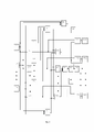
на фиг.1 представлена функциональная схема устройства, figure 1 shows a functional diagram of the device,
на фиг.2 - функциональная схема блока контроля режима работы АЭЭС. figure 2 - functional diagram of the control unit mode of operation of the AEPS.
Предлагаемое устройство содержит: по числу ГА датчики загрузки ГА 1.1, 1.2 … 1.n, блоки контроля увеличения загрузки 2.1, 2.2 … 2.n, блоки контроля уменьшения загрузки 3.1, 3.2 … 3.n, а также первый логический элемент «ИЛИ» 4 и блок контроля разности загрузок ГА 5, по числу ГА первые логические элементы «И» 6.1, 6.2, … 6.n, а также второй логический элемент «ИЛИ» 7, блок контроля режима работы АЭЭС 8, второй логический элемент «И» 9, блок блокировки включения потребителей 10, блок отключения потребителей 11, ждущий одновибратор с задержкой формирования импульса 12, по числу ГА: третьи логические элементы «И» 13.1, 13.2 … 13.n и блоки отключения ГА 14.1, 14.2 … 14.n; причем выход каждого из датчиков загрузки 1.1, 1.2 … 1.n соединен с входом соответствующего блока контроля увеличения загрузки 2.1, 2.2 … 2.n, с входом соответствующего блока контроля уменьшения загрузки 3.1, 3.2 … 3.n, соответствующим входом блока контроля разности загрузок ГА 5, соответствующим входом блока контроля режима работы АЭЭС 8, выход каждого из блоков контроля увеличения загрузки 2.1, 2.2 … 2.n соединен со вторым входом соответствующего из первых логических элементов «И» 6.1, 6.2, … 6.n и первым входом соответствующего из третьих логических элементов «И» 13.1, 13.2 … 13.n, выход каждого из блоков контроля уменьшения загрузки 3.1, 3.2 … 3.n соединен с соответствующим входом первого логического элемента «ИЛИ» 4, выход первого логического элемента «ИЛИ» 4 соединен с первыми входами всех первых логических элементов «И» 6.1, 6.2, … 6.n, выход блока контроля разности загрузок ГА 5 соединен с третьими входами всех первых логических элементов «И» 6.1, 6.2, … 6.n, выход каждого из первых логических элементов «И» 6.1, 6.2, … 6.n соединен с соответствующим входом второго логического элемента «ИЛИ» 7, выход которого соединен со вторым входом второго логического элемента «И» 9 и входом блока блокировки включения потребителей 10, выход второго логического элемента «И» 9 соединен с входом блока отключения потребителей 11 и входом ждущего одновибратора с задержкой формирования импульса 12, выход которого соединен со вторыми входами всех третьих логических элементов «И» 13.1, 13.2 … 13.n, выход каждого из третьих логических элементов «И» 13.1, 13.2 … 13.n соединен с входом соответствующего блока отключения ГА 14.1, 14.2 … 14.n.The proposed device contains: according to the number of GA load sensors GA 1.1, 1.2 ... 1.n, control blocks for increasing load 2.1, 2.2 ... 2.n, control blocks for reducing load 3.1, 3.2 ... 3.n, as well as the first logic element "OR" 4 and block for controlling the
Устройство может быть выполнено на следующих элементах:The device can be made on the following elements:
Датчики загрузки ГА 1.1, 1.2 … 1.n – известные функциональные блоки, формирующие на своем выходе сигналы в виде напряжения постоянного тока, пропорционального загрузке ГА (нагрузке сети, которую принимает на себя данный ГА). GA load sensors 1.1, 1.2 ... 1.n are well-known functional blocks that generate signals at their output in the form of a DC voltage proportional to the GA load (the network load that this GA takes on).
Блоки контроля увеличения загрузки 2.1, 2.2 … 2.n – известные функциональные блоки, формирующие на своих выходах сигнал логической «1», когда сигнал в виде напряжения на их входах увеличивается и сигнал логического «0» в противном случае. Load increase control blocks 2.1, 2.2 ... 2.n are well-known functional blocks that generate a logical “1” signal at their outputs when the signal in the form of voltage at their inputs increases and a logical “0” signal otherwise.
Блоки контроля уменьшения загрузки 3.1, 3.2 … 3.n - известные функциональные блоки, формирующие на своих выходах сигнал логической «1», когда сигнал в виде напряжения на их входах уменьшается и сигнал логического «0» в противном случае. Load reduction control blocks 3.1, 3.2 ... 3.n are well-known functional blocks that generate a logical “1” signal at their outputs when the signal in the form of voltage at their inputs decreases and a logical “0” signal otherwise.
Первые, второй и третьи логические элементы «И» 6.1, 6.2, … 6n, 9 и 13.1, 13.2 … 13.n – известные функциональные блоки, которые формируют на своих выходах сигналы логической «1», если на все их входы поступили сигналы логической «1», и сигнал логического «0» в противном случае.The first, second and third logical elements "AND" 6.1, 6.2, ... 6n, 9 and 13.1, 13.2 ... 13.n are known functional blocks that form logical "1" signals at their outputs if all of their inputs receive logical signals "1", and signal logical "0" otherwise.
Первый и второй логические элементы «ИЛИ» 4, 7 – известные функциональные блоки, которые формируют на своих выходах сигналы логической «1», если хотя бы на один из его входов поступил сигнал логической «1» и сигнал логического «0» в противном случае. The first and second logic elements "OR" 4, 7 are known functional blocks that generate logical "1" signals at their outputs, if at least one of its inputs received a logical "1" signal and a logical "0" signal otherwise .
Блок контроля разности загрузок ГА 5 – функциональный блок (имеющий n входов и один выход), на выходе которого появляется сигнал логической «1», если разность загрузок хотя бы одной из пар ГА из числа n превысит допустимое значение и будет увеличиваться. Для реализации данной функции все n ГА разбиты на возможное число пар (k) и вычисляется разность загрузок в каждой паре ГА. Вычисляется абсолютная величина разности загрузок каждой пары и контролируется ее увеличение. Если абсолютная величина хотя бы одной пары будет увеличиваться и при этом превысит допустимое значение разности загрузок ГА, то на выходе блока 5 сформируется сигнал логической «1». Блок 5 по своему назначению и конструкции полностью аналогичен блоку, используемому в прототипе.Load difference
Блок контроля режима работы АЭЭС 8 (Фиг.2) – новый функциональный блок, формирующий на своем выходе сигнал логической «1», если нагрузка сети АЭЭС не увеличивается, то есть остается неизменной или уменьшается и сигнал логического «0» в противном случае. На Фиг.2 представлена одна из возможных функциональных схем блока контроля режима работы АЭЭС. Блок 8 содержит блок сложения 15, блок контроля увеличения нагрузки 16 и логический элемент «НЕ» 17, причем выход блока сложения 15 соединен с входом блока контроля увеличения нагрузки 16, выход которого соединен с входом логического элемента «НЕ» 17.The AEES operating mode control unit 8 (Figure 2) is a new functional block that generates a logical “1” signal at its output if the AEES network load does not increase, that is, it remains unchanged or decreases and the logical “0” signal otherwise. Figure 2 shows one of the possible functional diagrams of the control unit of the operating mode of the AEPS.
Блок сложения 15 – известный функциональный блок, формирующий на своем выходе сигнал в виде напряжения, величина которого пропорциональна сумме сигналов, поступающих в виде напряжений на его входы, может быть выполнен на базе операционных усилителей. The
Блок контроля увеличения нагрузки 16 известный функциональный блок, формирующий на своем выходе сигнал логической «1», когда сигнал в виде напряжения на его входе увеличивается и сигнал логического «0» в противном случае. Полностью аналогичен каждому из блоков 3.1, 3.2 … 3.n.The load
Логический элемент «НЕ» 17 – известный функциональный блок, формирующий на своем выходе сигнал логического «0», если на его вход поступает сигнал логической «1» и сигнал логической «1», если на его вход поступает сигнал логического «0».The logical element "NOT" 17 is a well-known functional block that generates a logical "0" signal at its output if a logical "1" signal arrives at its input and a logical "1" signal if a logical "0" signal arrives at its input.
Блок контроля режима работы АЭЭС работает следующим образом. На входы блока сложения 15 с выходов датчиков загрузки ГА 1.1, 1.2 … 1.n (Фиг.1) поступают сигналы, пропорциональные загрузке соответствующих ГА, суммируются и на выходе блока сложения 15 формируется сигнал, пропорциональный суммарной загрузке всех работающих ГА, равной величине нагрузки сети АЭЭС. Сигнал, пропорциональный нагрузке сети поступает на вход блока контроля увеличения нагрузки 16. Если нагрузка сети увеличивается, то сигнал на выходе блока сложения 15 и входе контроля увеличения нагрузки 16 будет увеличиваться. На выходе блока контроля увеличения нагрузки 16 сформируется сигнал логической «1», который поступит на вход логического элемента «НЕ» 17. На выходе логического элемента «НЕ» 18 и выходе блока контроля режима работы АЭЭС 8 появится сигнал логического «0», информирующий о том, что АЭЭС находится в режиме увеличения нагрузки, при котором работа устройства для предупредительного управления АЭЭС нецелесообразна. Если нагрузка сети АЭЭС останется неизменной или уменьшится, то останется неизменным или уменьшится сигнал на выходе блока сложения 15 и входе блока контроля увеличения нагрузки 16, на выходе которого появится сигнал логической «1» и поступит на вход логического элемента «НЕ» 18. На выходе логического элемента «НЕ» 18 и выходе блока контроля режима работы АЭЭС 8 появится сигнал логической «1», информирующий о том, что АЭЭС находится в режиме, при котором ее нагрузка не увеличивается, и работа устройства для предупредительного управления АЭЭС целесообразна.The AEES operating mode control unit operates as follows. At the inputs of the
Блок блокировки включения потребителей 10 – известный функциональный блок, предотвращающий возможность включения потребителей при поступлении сигнала логической «1» на его вход. В качестве этого блока может быть использовано обычное электромагнитное реле, размыкающий контакт которого включен последовательно с кнопкой «Пуск» магнитного пускателя соответствующего потребителя. Аналогичные блоки используются для исключения возможности включения потребителей в момент работы системы синхронизации генераторов с целью предотвращения колебаний частоты сети. The block blocking the inclusion of
Блок отключения потребителей 11 – известный функциональный блок, обеспечивающий отключение соответствующих потребителей (групп потребителей) электроэнергии при поступлении сигнала логической «1» на его вход. В качестве такого блока может быть использовано обычное электромагнитное реле, размыкающие контакты которого включены в цепь катушки нулевой защиты автоматического выключателя соответствующего потребителя (группы потребителей) электрической энергииThe
Ждущий одновибратор с задержкой формирования импульса 12 – известный функциональный блок, формирующий на своем выходе сигнал логической «1» определенной длительности (tимп) через выдержку времени (tвыд) после появления сигнала логической «1» на его входе. Может быть выполнен на базе обычного ждущего одновибратора с цепью задержки на входе или на базе микросхемы LM 555 (m.grz.ru).The waiting one-shot with a
Блоки отключения ГА 14.1, 14.2 … 14.n - известные функциональные блоки, каждый из которых обеспечивает отключение соответствующего ГА при поступлении сигнала логической «1» на его вход. В качестве такого блока может быть использовано обычное электромагнитное реле, размыкающие контакты которого включены в цепь катушки нулевой защиты автоматического выключателя соответствующего генератора.GA shutdown blocks 14.1, 14.2 ... 14.n are well-known functional blocks, each of which ensures that the corresponding GA is turned off when a logical "1" signal is received at its input. As such a block, a conventional electromagnetic relay can be used, the breaking contacts of which are included in the circuit of the zero protection coil of the automatic switch of the corresponding generator.
Предлагаемое устройство работает следующим образом. The proposed device works as follows.
В случае внезапного отказа АЭЭС, при котором СУ сформировала постоянный сигнал на увеличение подачи топлива в первичный двигатель одного из ГА, например, g –го ГА, загрузка агрегата начнет увеличиваться. Тогда увеличивается значение выходного сигнала на выходе соответствующего датчика загрузки 1.g. Этот сигнал поступает на вход соответствующего блока контроля увеличения загрузки 2.g и g – ый вход блока контроля разности загрузок ГА 5. На выходе блока контроля увеличения загрузки 2.g формируется сигнал логической «1» и поступает на второй вход g –го из первых логических элементов «И» 6.g и первый вход g –го из третьих логических элементов «И» 13.g. Так как загрузка g –го ГА увеличивается, то загрузка оставшихся ГА начнет уменьшаться. При этом сигналы на выходах всех датчиков загрузки соответствующих ГА 1.1,1.2 … 1.n, кроме 1.g, начнут уменьшаться. Эти сигналы поступают на входы соответствующих блоков контроля уменьшения загрузки и соответствующие входы блока контроля разности загрузок ГА 5. На выходах блоков контроля уменьшения загрузки 3.1, 3.2 … 3.n, кроме 3.g, появится сигнал логической «1» и поступит на соответствующий вход первого логического элемента «ИЛИ» 4, на выходе которого также появится сигнал логической «1» и поступит на первые входы всех первых логических элементов «И» 6.1, 6.2, … 6.n. Так как сигнал на g-ом входе блока 5 увеличивается, а на остальных его входах уменьшается, то разность загрузок g –го ГА и остальных увеличивается и в момент, когда она превысит допустимое значение на выходе блока контроля разности загрузок ГА 5 появится сигнал логической «1» и поступит на третьи входы всех первых логических элементов «И» 6.1, 6.2, … 6.n. При этом на все входы g –го из первых логических элементов «И» 6.g поступит сигнал логической «1», на его выходе появится сигнал логической «1», который поступит на g-ый вход второго логического элемента «ИЛИ» 7. Так как на один из входов второго логического элемента «ИЛИ» 7 поступит сигнал логической «1» на его выходе тоже появится сигнал логической «1», свидетельствующий о неработоспособном техническом состоянии АЭЭС. В данном случае АЭЭС признается неработоспособной, если один (одни) из ГА увеличивают свою загрузку, в то время как другой (другие) уменьшают свою загрузку и при этом разность загрузок превышает допустимое значение и увеличивается. Сигнал логической «1» с выхода блока 7 поступит на второй вход второго логического элемента «И» 9 и вход блока блокировки включения потребителей 10, который предотвратит включение мощных потребителей и увеличение нагрузки АЭЭС во время предупредительного управления. Сигналы, пропорциональные величине загрузки соответствующих ГА с выходов датчиков загрузки 1.1,1.2 … 1.n поступят на соответствующие входы блока контроля режима работы АЭЭС 8. Если в момент возникновения неисправности нагрузка АЭЭС увеличивается, то на выходе блока 8 сформируется сигнал логического «0» и поступит на первый вход второго логического элемента «И» 9, заблокировав дальнейшую работу устройства до момента, когда увеличение нагрузки АЭЭС прекратится. Если в момент возникновения неисправности нагрузка АЭЭС остается постоянной или уменьшается, то на выходе блока 8 сформируется сигнал логической «1», который поступит на первый вход второго логического элемента «И» 9. Так как на оба входа второго логического элемента «И» 9 поступит сигнал логической «1», то на его выходе сформируется сигнал логической «1», информирующий о том, что произошла неисправность в АЭЭС, ее нагрузка не увеличивается и не увеличится во время работы устройства для ПУ. Сигнал логической «1» с выхода второго логического элемента «И» 9 поступит на вход блока отключения потребителей 11 и на вход ждущего одновибратора с задержкой формирования импульса 12. Блок отключения потребителей 11 отключит выбранные группы потребителей электроэнергии. Нагрузка сети уменьшится. Через время tвыд, равное времени отключения потребителей электроэнергии, на выходе ждущего одновибратора с задержкой формирования импульса 12 появится короткий сигнал логической «1», длительность которого tимп несколько больше, чем время срабатывания топливного регулятора (tсраб ) данной СУ. Этот сигнал поступит на вторые входы всех третьих логических элементов «И» 13.1, 13.2 … 13.n. Так как на оба входа g –го из вторых логических элементов «И» 13.g поступят сигналы логической «1», то на его выходе – тоже появится короткий сигнал логической «1», который поступит на вход g –го блока отключения ГА 14.g. Блок 14.g отключит g-ый ГА, что предотвратит наступление аварийной ситуации на АЭЭС.In the event of a sudden failure of the AEPS, in which the control system generated a constant signal to increase the fuel supply to the prime mover of one of the GA, for example, the g-th GA, the load of the unit will begin to increase. Then the value of the output signal at the output of the corresponding load sensor 1.g increases. This signal is fed to the input of the corresponding load increase control block 2.g and g is the th input of the load difference
Предположим, что неисправность АЭЭС, при которой СУ сформирует постоянный сигнал на увеличение подачи топлива в первичный двигатель одного из ГА при его параллельной работе хотя бы с одним из других генераторных агрегатов, не произойдет. В этом случае при снижении нагрузки АЭЭС в момент срабатывания блока 11загрузка g-го ГА начнет уменьшаться, на выходе блока контроля увеличения загрузки 2.g сформируется сигнал логического «0», который поступит на первый вход g-го из третьих логических элементов «И»13.g, на его выходе сохранится сигнал логического «0», отключения g-го ГА не произойдет. При этом разница в загрузках g-го ГА и остальных агрегатов перестанет увеличиваться и на выходе блока контроля разности загрузок ГА 5 появится сигнал логического «0» и поступит на третьи входы каждого из первых логических элементов «И» 6.1, 6.2, … 6n. На выходах всех первых логических элементов «И» 6.1, 6.2, … 6n и всех входах второго логического элемента «ИЛИ» 7 сформируется сигнал логического «0». На выходе второго логического элемента «ИЛИ» 7 появится сигнал логического «0», который поступит на вход блока блокировки включения потребителей 10, который снимет блокировку и разрешит дальнейшее включение потребителей. АЭЭС и устройство для ПУ будут приведены в исходное состояние и готовность к дальнейшей работе.Let us assume that the failure of the AEPS, in which the control system will generate a constant signal to increase the fuel supply to the prime mover of one of the GAs during its parallel operation with at least one of the other generating units, will not occur. In this case, when the AEPP load decreases, at the moment of operation of
Пример реализации работы устройства.An example of the implementation of the device.
Рассмотрим в качестве примера АЭЭС с двумя параллельно работающими ГА (ГА1 и ГА2 соответственно). Предположим, что номинальная мощность каждого из них – 100кВт (Рн1=Рн2=100кВт), точность распределения нагрузок-10%Рн (∆Рраспр =10%Рн=10кВт), время срабатывания топливного регулятора равно 0,5с (tсраб=0,5с ), время отключения потребителей электроэнергии (tотк) равно 0,3с. Для данной АЭЭС установим допустимое значение разности загрузок (∆Рдоп >∆Рраспр) ГА равным 15%Рн (∆Рдоп =15%Рн=15кВт), время задержки (выдержки) ждущего одновибратора с задержкой формирования импульса равным 0,3с (tвыд=tотк=0,3с), длительность сигнала логической «1» ждущего одновибратора с задержкой формирования импульса равным 0,7с (tимп=0,7с > tсраб=0,5c). Предположим, что загрузка ГА1 составила 65%Рн (Р1=65кВт), а загрузка ГА2 составила 60%Рн (Р2=60кВт). Предположим, что нагрузка АЭЭС меняется за счет работы буксирной лебедки, перемещающей груз в условиях сильного ветра. При этом при порывах ветра нагрузка АЭЭС возрастает, а при ослаблении ветра – уменьшается.Consider, as an example, an AEPP with two GAs operating in parallel (GA1 and GA2, respectively). Suppose that the rated power of each of them is 100kW (Rn1=Rn2=100kW), the load distribution accuracy is 10%Rn (∆Rdistribution=10%Rn=10kW), the response time of the fuel regulator is 0.5s (tsrab=0.5s ), the time of disconnection of electricity consumers (topen) is equal to 0.3 s. For this AEPP, we set the allowable value of the load difference (∆Рdop >∆Рdistribution) of the HA equal to 15%Рn (∆Рdop =15%Рn=15kW), the delay (hold) time of the waiting single vibrator with the pulse formation delay equal to 0.3s (tvyd=topen\u003d 0.3 s), the duration of the signal of the logical "1" of the waiting one-shot with a pulse formation delay equal to 0.7 s (timp\u003d 0.7s\u003e tsrab=0.5c). Let us assume that the load of HA1 was 65%Rn (P1=65kW), and the load of HA2 was 60%Rn (P2=60kW). Let us assume that the AEPP load changes due to the operation of the towing winch, which moves the load in strong wind conditions. At the same time, when the wind gusts, the load of the AEPS increases, and when the wind weakens, it decreases.
Допустим, что в процессе эксплуатации произошла неисправность СУ АЭЭС, при которой СУ сформировала постоянный сигнал на увеличение подачи топлива в первичный двигатель ГА1. При этом ГА1 начнет принимать на себя нагрузку, его загрузка начет увеличиваться, а загрузка ГА2 уменьшаться. Так как загрузка ГА1 будет увеличиваться, увеличится и сигнал на выходе датчика загрузки 1.1 устройства (Фиг.1), который поступит на вход блока контроля увеличения загрузки 2.1 и первый вход блока контроля разности загрузок ГА 5. На выходе блока 2.1 появится сигнал логической «1» и поступит на второй вход первого из первых логических элементов «И» 6.1 и первый вход первого из вторых логических элементов «И» 13.1. Так как ГА2 будет разгружаться, на выходе датчика загрузки 1.2 сигнал уменьшится и поступит на вход блока уменьшения загрузки 3.2 и второй вход блока контроля разности загрузок ГА 5. На выходе блока контроля уменьшения загрузки 3.2 сформируется сигнал логической «1» и поступит на второй вход первого логического элемента «ИЛИ» 4, на выходе которого появится сигнал логической «1» и поступит на первые входы всех первых логических элементов «И» 6.1 и 6.2. В момент, когда разница загрузок ГА превысит допустимое значение (∆Р>∆Рдоп), например, когда загрузка агрегатов составит: Р1=70,5кВт, а Р2=54,5 кВт, и продолжит увеличиваться, так как ГА1 будет загружаться, а ГА2 разгружаться, на выходе блока контроля разности загрузок ГА 5 сформируется сигнал логической «1» и поступит на третьи входы первых логических элементов «И» 6.1 и 6.2. Так как на все три входа первого из первых логических элементов «И» 6.1 поступят сигналы логической «1» то и на его выходе – сигнал логической «1», который поступит на первый вход второго логического элемента «ИЛИ» 7. При поступлении сигнала логической «1» на первый вход второго логического элемента «ИЛИ» 7 на его выходе сформируется сигнал логической «1», информирующий о том, что АЭЭС неработоспособна. Сигнал логической «1» с выхода блока 7 поступит на вход блока блокировки включения потребителей 10 и второй вход второго логического элемента «И» 9. Блок блокировки включения потребителей 10 заблокирует включение дополнительных потребителей, предотвращая возможное увеличение нагрузки АЭЭС. При этом сигналы, пропорциональные загрузке ГА1 и ГА2 с выходов датчиков загрузки 1.1 и 1.2 поступят на первый и второй входы блока контроля режима работы АЭЭС 8. Предположим, что в момент возникновения неисправности или непосредственно перед ним произошел порыв ветра, нагрузка буксирной лебедки увеличилась, увеличилась и нагрузка сети АЭЭС. В этом случае на выходе блока контроля режима работы АЭЭС 8 появится сигнал логического «0» и поступит на первый вход второго логического элемента «И» 9. На выходе второго логического элемента «И» сохранится сигнал логического «0», запрещающий дальнейшую работу устройства для ПУ. В следующий момент времени произойдет ослабление ветра, и нагрузка на буксирную лебедку и общая нагрузка АЭЭС начнут уменьшаться. При этом на выходе блока контроля режима работы АЭЭС 8 сформируется сигнал логической «1» и поступит на первый вход второго логического элемента «И» 9. Так как на оба входа второго логического элемента «И» 9 поступят сигналы логической «1», то на его выходе появится сигнал логической «1». Сигнал логической «1» с выхода второго логического элемента «И» 9 поступит на вход блока отключения потребителей 11 и вход ждущего одновибратора с задержкой формирования импульса 12. Блок 11 отключит группы потребителей электроэнергии за время tотк=0,3с, осуществляя уменьшение нагрузки АЭЭС до значения, менее номинального, например, до 90 кВт. Через выдержку времени tвыд=tотк=0,3с на выходе ждущего одновибратора с задержкой формирования импульса 12 появится короткий импульс логической «1» и поступит на вторые входы третьих логических элементов «И» 13.1 и 13.2. Так как на оба входа первого из вторых логических элементов «И» 13.1 поступят сигналы логической «1», то на его выходе тоже сформируется сигнал логической «1» и поступит на вход блока отключения первого ГА 14.1. ГА1 отключится от сети. Нагрузка сети не велика и ГА2 примет ее на себя, осуществляя переход неработоспособной АЭЭС в режим правильного функционирования без аварийной ситуации, связанной с перерывом в электроснабжении сети.Let us assume that during operation a malfunction of the control system of the AEPP occurred, in which the control system generated a constant signal to increase the fuel supply to the prime mover GA1. At the same time, GA1 will begin to take on the load, its load will increase, and the load of GA2 will decrease. Since the loading of GA1 will increase, the signal at the output of the load sensor 1.1 of the device (Figure 1) will also increase, which will go to the input of the load increase control block 2.1 and the first input of the load difference
Предлагаемое изобретение было создано в составе научно-исследовательских работ, проводимых на кафедре «Электропривода и электрооборудования береговых установок» ФБГОУ ВО «Государственного университета морского и речного флота имени адмирала С.О. Макарова». Были произведены расчеты, показавшие возможность использования заявляемого устройства в судовых энергетических установках и электроэнергетических системах, что с учетом выше изложенного позволяет сделать вывод о возможности его промышленного применения.The proposed invention was created as part of the research work carried out at the Department of "Electric drive and electrical equipment of coastal installations" of the State University of the Sea and River Fleet named after Admiral S.O. Makarov". Calculations were made that showed the possibility of using the proposed device in ship power plants and electric power systems, which, taking into account the above, allows us to conclude that it is possible to use it industrially.
Claims (1)
Publications (1)
| Publication Number | Publication Date |
|---|---|
| RU2773503C1 true RU2773503C1 (en) | 2022-06-06 |
Family
ID=
Citations (5)
| Publication number | Priority date | Publication date | Assignee | Title |
|---|---|---|---|---|
| US20140307357A1 (en) * | 2013-04-12 | 2014-10-16 | Emerson Electric Company | Systems and methods for detecting over/under excitation faults |
| US20160094036A1 (en) * | 2014-09-25 | 2016-03-31 | Remy Technologies, Llc | System of parallel-connected generators and method for load share balancing therein using a serial communication network |
| US20170373498A1 (en) * | 2015-01-23 | 2017-12-28 | Siemens Aktiengesellschaft | Distribution of electric energy on a vessel |
| RU2686103C1 (en) * | 2018-07-12 | 2019-04-24 | Федеральное государственное бюджетное образовательное учреждение высшего образования "Государственный университет морского и речного флота имени адмирала С.О. Макарова" | Method for determination of inoperative generator unit |
| RU2739364C1 (en) * | 2020-09-07 | 2020-12-23 | Николай Викторович Широков | Method for preventive control of ship electric power system |
Patent Citations (5)
| Publication number | Priority date | Publication date | Assignee | Title |
|---|---|---|---|---|
| US20140307357A1 (en) * | 2013-04-12 | 2014-10-16 | Emerson Electric Company | Systems and methods for detecting over/under excitation faults |
| US20160094036A1 (en) * | 2014-09-25 | 2016-03-31 | Remy Technologies, Llc | System of parallel-connected generators and method for load share balancing therein using a serial communication network |
| US20170373498A1 (en) * | 2015-01-23 | 2017-12-28 | Siemens Aktiengesellschaft | Distribution of electric energy on a vessel |
| RU2686103C1 (en) * | 2018-07-12 | 2019-04-24 | Федеральное государственное бюджетное образовательное учреждение высшего образования "Государственный университет морского и речного флота имени адмирала С.О. Макарова" | Method for determination of inoperative generator unit |
| RU2739364C1 (en) * | 2020-09-07 | 2020-12-23 | Николай Викторович Широков | Method for preventive control of ship electric power system |
Similar Documents
| Publication | Publication Date | Title |
|---|---|---|
| US9543748B2 (en) | Fault protection system for a power system of dynamically positioned vessel | |
| AU2017332958B2 (en) | Drive control apparatus and method for yaw motor of wind turbine | |
| EP3734832B1 (en) | Method, device, and system for controlling operation of generator | |
| WO2015028621A1 (en) | Power plant protection | |
| RU2773503C1 (en) | Device for preventive control of autonomous electric power system | |
| US11277007B2 (en) | Power conversion device, power system and method of suppressing reactive power in power system | |
| RU2739364C1 (en) | Method for preventive control of ship electric power system | |
| RU2758453C1 (en) | Method for preventive control of the ship's electric power system | |
| RU2785561C1 (en) | Method for preventive control of autonomous electric power system | |
| RU2681522C1 (en) | Method of protection of the ship electric power system | |
| RU2801395C1 (en) | Device for preventive control of ship electric power system | |
| RU2731756C1 (en) | Method for preventive control of generator unit switching off | |
| RU2802913C1 (en) | Method for preventive control of ship electric power system | |
| RU2736880C1 (en) | Method for preventive unloading of independent electric power system | |
| JP4149962B2 (en) | Isolated operation prevention device | |
| RU2758465C1 (en) | Device for preventive control of ship's electric power system | |
| US11764665B2 (en) | Control of a modular multilevel converter of a full bridge or mixed arm type in case of a DC line disturbance | |
| RU2653706C1 (en) | Method for protecting mains of stand-alone power plant | |
| RU2784000C1 (en) | Apparatus for preventive control of the electric power system of a ship | |
| RU2702730C1 (en) | Method for automatic unloading of parallel operating generators | |
| RU2742817C1 (en) | Device for preventive control of generator unit switching off | |
| RU2846318C1 (en) | Method for preventive control of a shipboard electric power system | |
| RU2682172C1 (en) | Method for automatic unloading of concurrent operating generator units | |
| RU2681940C1 (en) | Method of protection of the ship electric power system | |
| RU2828827C1 (en) | Device for preventive control of ship electric power system |