RU2768604C2 - Electrosurgical device for supplying radio-frequency energy and/or microwave energy to biological tissue - Google Patents
Electrosurgical device for supplying radio-frequency energy and/or microwave energy to biological tissue Download PDFInfo
- Publication number
- RU2768604C2 RU2768604C2 RU2020106129A RU2020106129A RU2768604C2 RU 2768604 C2 RU2768604 C2 RU 2768604C2 RU 2020106129 A RU2020106129 A RU 2020106129A RU 2020106129 A RU2020106129 A RU 2020106129A RU 2768604 C2 RU2768604 C2 RU 2768604C2
- Authority
- RU
- Russia
- Prior art keywords
- protective housing
- electrosurgical instrument
- instrument according
- energy
- distal end
- Prior art date
Links
Images

Classifications
-
- A—HUMAN NECESSITIES
- A61—MEDICAL OR VETERINARY SCIENCE; HYGIENE
- A61B—DIAGNOSIS; SURGERY; IDENTIFICATION
- A61B18/00—Surgical instruments, devices or methods for transferring non-mechanical forms of energy to or from the body
- A61B18/18—Surgical instruments, devices or methods for transferring non-mechanical forms of energy to or from the body by applying electromagnetic radiation, e.g. microwaves
- A61B18/1815—Surgical instruments, devices or methods for transferring non-mechanical forms of energy to or from the body by applying electromagnetic radiation, e.g. microwaves using microwaves
-
- A—HUMAN NECESSITIES
- A61—MEDICAL OR VETERINARY SCIENCE; HYGIENE
- A61B—DIAGNOSIS; SURGERY; IDENTIFICATION
- A61B17/00—Surgical instruments, devices or methods, e.g. tourniquets
- A61B17/34—Trocars; Puncturing needles
- A61B17/3478—Endoscopic needles, e.g. for infusion
-
- A—HUMAN NECESSITIES
- A61—MEDICAL OR VETERINARY SCIENCE; HYGIENE
- A61B—DIAGNOSIS; SURGERY; IDENTIFICATION
- A61B18/00—Surgical instruments, devices or methods for transferring non-mechanical forms of energy to or from the body
- A61B18/04—Surgical instruments, devices or methods for transferring non-mechanical forms of energy to or from the body by heating
- A61B18/12—Surgical instruments, devices or methods for transferring non-mechanical forms of energy to or from the body by heating by passing a current through the tissue to be heated, e.g. high-frequency current
- A61B18/14—Probes or electrodes therefor
- A61B18/148—Probes or electrodes therefor having a short, rigid shaft for accessing the inner body transcutaneously, e.g. for neurosurgery or arthroscopy
-
- A—HUMAN NECESSITIES
- A61—MEDICAL OR VETERINARY SCIENCE; HYGIENE
- A61B—DIAGNOSIS; SURGERY; IDENTIFICATION
- A61B18/00—Surgical instruments, devices or methods for transferring non-mechanical forms of energy to or from the body
- A61B18/18—Surgical instruments, devices or methods for transferring non-mechanical forms of energy to or from the body by applying electromagnetic radiation, e.g. microwaves
-
- A—HUMAN NECESSITIES
- A61—MEDICAL OR VETERINARY SCIENCE; HYGIENE
- A61B—DIAGNOSIS; SURGERY; IDENTIFICATION
- A61B18/00—Surgical instruments, devices or methods for transferring non-mechanical forms of energy to or from the body
- A61B2018/00053—Mechanical features of the instrument of device
- A61B2018/00059—Material properties
- A61B2018/00071—Electrical conductivity
-
- A—HUMAN NECESSITIES
- A61—MEDICAL OR VETERINARY SCIENCE; HYGIENE
- A61B—DIAGNOSIS; SURGERY; IDENTIFICATION
- A61B18/00—Surgical instruments, devices or methods for transferring non-mechanical forms of energy to or from the body
- A61B2018/00053—Mechanical features of the instrument of device
- A61B2018/00107—Coatings on the energy applicator
- A61B2018/00148—Coatings on the energy applicator with metal
-
- A—HUMAN NECESSITIES
- A61—MEDICAL OR VETERINARY SCIENCE; HYGIENE
- A61B—DIAGNOSIS; SURGERY; IDENTIFICATION
- A61B18/00—Surgical instruments, devices or methods for transferring non-mechanical forms of energy to or from the body
- A61B2018/00571—Surgical instruments, devices or methods for transferring non-mechanical forms of energy to or from the body for achieving a particular surgical effect
- A61B2018/00601—Cutting
-
- A—HUMAN NECESSITIES
- A61—MEDICAL OR VETERINARY SCIENCE; HYGIENE
- A61B—DIAGNOSIS; SURGERY; IDENTIFICATION
- A61B18/00—Surgical instruments, devices or methods for transferring non-mechanical forms of energy to or from the body
- A61B2018/00982—Surgical instruments, devices or methods for transferring non-mechanical forms of energy to or from the body combined with or comprising means for visual or photographic inspections inside the body, e.g. endoscopes
-
- A—HUMAN NECESSITIES
- A61—MEDICAL OR VETERINARY SCIENCE; HYGIENE
- A61B—DIAGNOSIS; SURGERY; IDENTIFICATION
- A61B18/00—Surgical instruments, devices or methods for transferring non-mechanical forms of energy to or from the body
- A61B18/04—Surgical instruments, devices or methods for transferring non-mechanical forms of energy to or from the body by heating
- A61B18/12—Surgical instruments, devices or methods for transferring non-mechanical forms of energy to or from the body by heating by passing a current through the tissue to be heated, e.g. high-frequency current
- A61B18/14—Probes or electrodes therefor
- A61B2018/1405—Electrodes having a specific shape
- A61B2018/1412—Blade
-
- A—HUMAN NECESSITIES
- A61—MEDICAL OR VETERINARY SCIENCE; HYGIENE
- A61B—DIAGNOSIS; SURGERY; IDENTIFICATION
- A61B18/00—Surgical instruments, devices or methods for transferring non-mechanical forms of energy to or from the body
- A61B18/18—Surgical instruments, devices or methods for transferring non-mechanical forms of energy to or from the body by applying electromagnetic radiation, e.g. microwaves
- A61B18/1815—Surgical instruments, devices or methods for transferring non-mechanical forms of energy to or from the body by applying electromagnetic radiation, e.g. microwaves using microwaves
- A61B2018/183—Surgical instruments, devices or methods for transferring non-mechanical forms of energy to or from the body by applying electromagnetic radiation, e.g. microwaves using microwaves characterised by the type of antenna
- A61B2018/1838—Dipole antennas
-
- A—HUMAN NECESSITIES
- A61—MEDICAL OR VETERINARY SCIENCE; HYGIENE
- A61B—DIAGNOSIS; SURGERY; IDENTIFICATION
- A61B18/00—Surgical instruments, devices or methods for transferring non-mechanical forms of energy to or from the body
- A61B18/18—Surgical instruments, devices or methods for transferring non-mechanical forms of energy to or from the body by applying electromagnetic radiation, e.g. microwaves
- A61B18/1815—Surgical instruments, devices or methods for transferring non-mechanical forms of energy to or from the body by applying electromagnetic radiation, e.g. microwaves using microwaves
- A61B2018/1861—Surgical instruments, devices or methods for transferring non-mechanical forms of energy to or from the body by applying electromagnetic radiation, e.g. microwaves using microwaves with an instrument inserted into a body lumen or cavity, e.g. a catheter
-
- A—HUMAN NECESSITIES
- A61—MEDICAL OR VETERINARY SCIENCE; HYGIENE
- A61B—DIAGNOSIS; SURGERY; IDENTIFICATION
- A61B18/00—Surgical instruments, devices or methods for transferring non-mechanical forms of energy to or from the body
- A61B18/18—Surgical instruments, devices or methods for transferring non-mechanical forms of energy to or from the body by applying electromagnetic radiation, e.g. microwaves
- A61B18/1815—Surgical instruments, devices or methods for transferring non-mechanical forms of energy to or from the body by applying electromagnetic radiation, e.g. microwaves using microwaves
- A61B2018/1876—Surgical instruments, devices or methods for transferring non-mechanical forms of energy to or from the body by applying electromagnetic radiation, e.g. microwaves using microwaves with multiple frequencies
-
- A—HUMAN NECESSITIES
- A61—MEDICAL OR VETERINARY SCIENCE; HYGIENE
- A61B—DIAGNOSIS; SURGERY; IDENTIFICATION
- A61B2218/00—Details of surgical instruments, devices or methods for transferring non-mechanical forms of energy to or from the body
- A61B2218/001—Details of surgical instruments, devices or methods for transferring non-mechanical forms of energy to or from the body having means for irrigation and/or aspiration of substances to and/or from the surgical site
- A61B2218/002—Irrigation
-
- A—HUMAN NECESSITIES
- A61—MEDICAL OR VETERINARY SCIENCE; HYGIENE
- A61B—DIAGNOSIS; SURGERY; IDENTIFICATION
- A61B2218/00—Details of surgical instruments, devices or methods for transferring non-mechanical forms of energy to or from the body
- A61B2218/001—Details of surgical instruments, devices or methods for transferring non-mechanical forms of energy to or from the body having means for irrigation and/or aspiration of substances to and/or from the surgical site
- A61B2218/007—Aspiration
Abstract
Description
ОБЛАСТЬ ТЕХНИКИFIELD OF TECHNOLOGY
Изобретение относится к электрохирургическому устройству и устройству для подачи радиочастотной энергии и/или энергии микроволновой частоты в биологическую ткань. В частности, изобретение относится к электрохирургическому инструменту, способному передавать радиочастотную (РЧ) энергию для рассечения ткани и/или энергию микроволновой частоты для гемостаза (т.е. для стимуляции свертывания крови). Изобретение может быть особенно подходящим для желудочно-кишечных (ЖК) процедур, связанных с нижним и верхним отделами желудочно-кишечного тракта, например, для удаления полипов на кишечнике, т.е. для эндоскопической резекции слизистой оболочки или эндоскопической диссекции подслизистого слоя. Изобретение также может быть использовано для других процедур, например в общей хирургии или лапароскопической хирургии. Изобретение может быть применено при процедурах на ухе, носу и горле, а также при резекции печени. Кроме того, устройство можно использовать для выполнения процедур, связанных с поджелудочной железой, например, для резекции или удаления опухолей или патологий в непосредственной близости от воротной вены или главного протока поджелудочной железы.The invention relates to an electrosurgical device and a device for supplying radio frequency energy and/or microwave frequency energy to biological tissue. In particular, the invention relates to an electrosurgical instrument capable of transmitting radio frequency (RF) energy for tissue dissection and/or microwave frequency energy for hemostasis (ie, to stimulate blood clotting). The invention may be particularly suitable for gastrointestinal (GI) procedures associated with the lower and upper gastrointestinal tract, for example, removal of polyps in the intestine, i. for endoscopic mucosal resection or endoscopic submucosal dissection. The invention can also be used for other procedures such as general surgery or laparoscopic surgery. The invention can be applied in ear, nose and throat procedures, as well as in liver resection. In addition, the device can be used to perform procedures related to the pancreas, such as resection or removal of tumors or pathologies in the vicinity of the portal vein or the main pancreatic duct.
УРОВЕНЬ ТЕХНИКИBACKGROUND OF THE INVENTION
Хирургическая резекция представляет собой способ удаления участков органов внутри тела человека или животного. Такие органы могут быть высоко васкуляризированными. При разрезе (разделении или рассечении) ткани небольшие кровеносные сосуды, называемые артериолами, повреждаются или разрываются. После первоначального кровотечения запускается система свертывания крови, при которой создается сгусток крови в попытке перекрыть кровоточащий участок. Желательно, чтобы во время операции пациент терял как можно меньше крови, поэтому были разработаны различные устройства в стремлении обеспечить рассечение без потери крови. При эндоскопических процедурах кровотечения также нежелательны и требуют надлежащего решения, поскольку кровоток может препятствовать обзору оперирующего хирурга, из-за чего операция может продлиться дольше и, возможно, привести к тому, что потребовалось бы прекратить данную операцию и вместо этого использовать другой способ, например открытую хирургическую операцию.Surgical resection is a method of removing portions of organs within the human or animal body. Such organs may be highly vascularized. When tissue is cut (divided or cut), small blood vessels called arterioles are damaged or ruptured. After the initial bleeding, the blood clotting system kicks in, creating a blood clot in an attempt to seal off the bleeding site. It is desirable that the patient lose as little blood as possible during the operation, so various devices have been developed in an effort to provide a cut without blood loss. In endoscopic procedures, bleeding is also undesirable and needs to be properly addressed, as blood flow may obstruct the view of the operating surgeon, which may cause the operation to take longer and possibly lead to the need to stop this operation and instead use another method, such as open surgical operation.
Электрохирургические генераторы широко применяются в больничных операционных, нередко используются при открытых и лапароскопических операциях, а также все чаще используются с хирургическими устройствами для осмотра, например с эндоскопом и т.п. При эндоскопических операциях электрохирургическое приспособление обычно вводят через просвет внутри эндоскопа. В сравнении с аналогичным каналом доступа при проведении лапароскопической хирургической операции такой просвет в канале является сравнительно узким и более длинным.Electrosurgical generators are widely used in hospital operating rooms, are often used in open and laparoscopic surgeries, and are increasingly being used with surgical examination devices such as endoscopes and the like. In endoscopic procedures, an electrosurgical device is usually inserted through a lumen within the endoscope. Compared to a similar access channel during laparoscopic surgery, such a lumen in the channel is relatively narrow and longer.
Известно, что вместо острого лезвия используется радиочастотная (РЧ) энергия для разреза биологической ткани. Принцип применения способа разрезания с использованием радиочастотной энергии состоит в том, что при прохождении электрического тока через матрицу ткани (при помощи ионного содержимого клеток и межклеточных электролитов) полное сопротивление потоку электронов через ткань генерирует тепло. На практике прибор выполнен с возможностью подачи в матрицу ткани РЧ напряжения, которое достаточно для выделения тепла внутри клеток для испарения содержания воды в ткани. Однако в результате этого увеличивающегося обезвоживания, особенно рядом с участком РЧ излучения инструмента (который имеет наибольшую плотность тока по пути прохождения тока через ткань), может быть утерян прямой физический контакт между тканью и инструментом. Затем приложенное напряжение проявляется через падение напряжения в пределах этой небольшой полости, вызывающее ионизацию в пустоте, которая приводит к образованию плазмы. Плазма имеет очень высокое объемное удельное сопротивление по сравнению с тканью. Энергия, подаваемая на инструмент, поддерживает плазму, т.е. замыкает электрическую цепь между инструментом и тканью. Летучее вещество, попадающее в плазму, может испаряться, и поэтому происходит восприятие того, что плазма рассекает ткань.It is known that instead of a sharp blade, radio frequency (RF) energy is used to cut biological tissue. The principle of applying the method of cutting using radio frequency energy is that when an electric current passes through the tissue matrix (using the ionic content of cells and intercellular electrolytes), the impedance to the flow of electrons through the tissue generates heat. In practice, the device is configured to apply an RF voltage to the tissue matrix that is sufficient to generate heat within the cells to vaporize the water content of the tissue. However, as a result of this increasing dehydration, especially near the RF site of the instrument (which has the highest current density along the current path through the tissue), direct physical contact between tissue and instrument may be lost. The applied voltage then manifests itself as a voltage drop within this small cavity, causing ionization in the void, which leads to the formation of a plasma. Plasma has a very high volume resistivity compared to tissue. The energy applied to the tool maintains the plasma, i.e. closes the electrical circuit between the tool and the cloth. A volatile substance that enters the plasma can evaporate, and therefore there is a perception that the plasma cuts through the tissue.
В GB 2 523 246 описан электрохирургический инструмент для подачи в биологическую ткань РЧ электромагнитной энергии и/или электромагнитной (ЭМ) энергии микроволновой частоты. Инструмент содержит стержень, вводимый через канал инструмента хирургического устройства для осмотра. На дистальном конце стержень находится наконечник инструмента, содержащий плоскую линию передачи, образованную из листа первого диэлектрического материала, имеющего первый и второй проводящие слои на своих противоположных поверхностях. Плоская линия передачи соединена с коаксиальным кабелем, который подводится стержнем. Коаксиальный кабель предназначен для подачи микроволновой или РЧ энергии на плоскую линию передачи. Коаксиальный кабель содержит внутренний проводник, внешний проводник, соосный с внутренним проводником, и второй диэлектрический материал, разделяющий внешний и внутренний проводники, причем внутренний и внешний проводники проходят за второй диэлектрик в месте соединительной области контакта для перекрытия противоположных поверхностей линии передачи и электрического контакта соответственно первого проводящего слоя и второго проводящего слоя. Инструмент дополнительно содержит защитный корпус, имеющий выпуклую нижнюю поверхность с плавными обводами, обращенную в сторону от плоской линии передачи. В нижней поверхности образован проходящий в продольном направлении утопленный канал. Внутри инструмента установлена выдвижная игла, которая может проходить через утопленный канал и выступать из дистального конца инструмента. Игла может использоваться для впрыскивания жидкости в зону обработки до подачи РЧ или микроволновой энергии.GB 2 523 246 describes an electrosurgical instrument for delivering RF electromagnetic energy and/or microwave frequency electromagnetic (EM) energy into biological tissue. The instrument comprises a rod inserted through the instrument channel of the surgical examination device. At the distal end of the rod is a tool tip containing a flat transmission line formed from a sheet of the first dielectric material having the first and second conductive layers on their opposite surfaces. The flat transmission line is connected to a coaxial cable which is brought in by a rod. Coaxial cable is designed to carry microwave or RF energy to a flat transmission line. The coaxial cable contains an inner conductor, an outer conductor coaxial with the inner conductor, and a second dielectric material separating the outer and inner conductors, with the inner and outer conductors passing behind the second dielectric at the site of the connecting contact area to overlap the opposite surfaces of the transmission line and electrical contact, respectively, of the first conductive layer and a second conductive layer. The tool additionally contains a protective housing having a convex lower surface with smooth contours, facing away from the flat transmission line. A recessed channel extending in the longitudinal direction is formed in the lower surface. A retractable needle is installed inside the instrument, which can pass through the recessed channel and protrude from the distal end of the instrument. The needle may be used to inject liquid into the treatment area prior to the delivery of RF or microwave energy.
СУЩНОСТЬ ИЗОБРЕТЕНИЯSUMMARY OF THE INVENTION
В наиболее общем смысле данное изобретение обеспечивает разработку концепции, рассмотренной в GB 2 523 246. Указанная разработка может включать в себя формирование защитного корпуса в виде профильной детали электропроводящего биосовместимого материала, имеющего низкий коэффициент трения с биологической тканью (например, из нержавеющей стали), который выполняет двойную функцию (i) физической защиты ткани, которая находится под активным наконечником и (ii) обеспечения электрического соединения между коаксиальной линией подачи и активным наконечником.In the most general sense, this invention provides a development of the concept discussed in GB 2 523 246. This development may include the formation of a protective housing in the form of a profile part of an electrically conductive biocompatible material having a low coefficient of friction with biological tissue (for example, stainless steel), which performs the dual function of (i) physically protecting the tissue that is under the active tip and (ii) providing an electrical connection between the coaxial supply line and the active tip.
Защитный корпус может быть особенно необходимым при осуществлении процедур в желудочно-кишечном тракте, когда вызывает беспокойство прободение кишечника, или в поджелудочной железе, когда существует риск повреждения воротной вены или главного протока поджелудочной железы при резекции, рассечении или удалении опухоли или другой патологии. A protective sheath may be particularly necessary in procedures in the gastrointestinal tract when bowel perforation is a concern, or in the pancreas where there is a risk of damage to the portal vein or main pancreatic duct from resection, dissection, or removal of a tumor or other pathology.
Защитный корпус может использоваться для охвата плоских наконечников инструментов, приспособленных для различных функций. Например, аспекты изобретения, рассматриваемые в данном документе, включают в себя: инструмент, выполненный с возможностью подачи радиочастотной (РЧ) энергии для разрезания биологической ткани; инструмент, выполненный с возможностью подачи как РЧ энергии, так и энергии микроволновой частоты отдельно или одновременно; и инструмент, выполненный с возможностью подачи РЧ энергии и/или микроволновой энергии и содержащий выдвижную иглу для подачи текучей среды (жидкости или газа) в место обработки или удаления текучей среды из него. Например, иглу можно использовать для введения газа, например аргона, чтобы генерировать термическую или нетермическую плазму для (термической) коагуляции или (нетермической) стерилизации поверхности. РЧ и/или микроволновое поле может использоваться для выработки и поддержания или создания этой плазмы. Защитный корпус может содержать канал, например утопленный канал, через который перемещается выдвижная игла или через который может подаваться жидкость без использования иглы, например, для клинических целей или для очистки.The protective housing can be used to enclose the flat tips of instruments adapted for various functions. For example, aspects of the invention discussed herein include: an instrument capable of delivering radio frequency (RF) energy to cut biological tissue; a tool configured to supply both RF energy and microwave energy separately or simultaneously; and a tool configured to deliver RF energy and/or microwave energy and comprising a retractable needle for delivering a fluid (liquid or gas) to or removing fluid from the treatment site. For example, a needle can be used to introduce a gas, such as argon, to generate thermal or non-thermal plasma for (thermal) coagulation or (non-thermal) surface sterilization. An RF and/or microwave field can be used to generate and maintain or create this plasma. The protective housing may include a channel, such as a recessed channel, through which a retractable needle is moved or through which liquid can be supplied without the use of a needle, for example, for clinical purposes or for cleaning.
В соответствии с изобретением предоставлен электрохирургический инструмент для подачи электромагнитной энергии в биологическую ткань, причем инструмент содержит: узел дистального конца, содержащий: активный наконечник, содержащий плоский корпус, изготовленный из первого диэлектрического материала, отделяющего первый проводящий элемент на его первой поверхности от второго проводящего элемента на его второй поверхности, причем вторая поверхность обращена в направлении, противоположном направлению первой поверхности; электропроводящий защитный корпус, установленный на нижней стороне активного наконечника, причем защитный корпус имеет гладко профилированную выпуклую нижнюю поверхность, обращенную в сторону от плоского корпуса; и коаксиальный кабель питания, содержащий внутренний проводник, внешний проводник, соосный с внутренним проводником, и второй диэлектрический материал, разделяющий внутренний и внешний проводники, причем коаксиальный кабель питания предназначен для передачи РЧ ЭМ или микроволновой ЭМ энергии, причем внутренний проводник электрически соединен с первым проводящим элементом, а внешний проводник электрически соединен со вторым проводящим элементом посредством защитного корпуса для приема наконечником инструмента РЧ и/или микроволнового сигнала, и при этом первый и второй проводящие элементы расположены так, чтобы излучать РЧ ЭМ энергию или микроволновую ЭМ энергию от коаксиального кабеля в дистальной боковой части плоского корпуса. При такой компоновке сам защитный корпус обеспечивает проводящий путь между коаксиальным кабелем и активным наконечником, так что не требуется дополнительных соединительных компонентов.In accordance with the invention, an electrosurgical instrument is provided for supplying electromagnetic energy to a biological tissue, the instrument comprising: a distal end assembly comprising: an active tip comprising a flat body made of a first dielectric material separating a first conductive element on its first surface from a second conductive element on its second surface, the second surface facing in a direction opposite to that of the first surface; an electrically conductive protective housing mounted on the underside of the active tip, and the protective housing has a smoothly shaped convex bottom surface facing away from the flat body; and a coaxial power cable comprising an inner conductor, an outer conductor coaxial with the inner conductor, and a second dielectric material separating the inner and outer conductors, wherein the coaxial power cable is designed to transmit RF EM or microwave EM energy, the inner conductor being electrically connected to the first conductive element, and the outer conductor is electrically connected to the second conductive element through a protective housing for receiving an RF and/or microwave signal by the tip of the instrument, and the first and second conductive elements are located so as to radiate RF EM energy or microwave EM energy from the coaxial cable in the distal side of the flat body. With this arrangement, the protective housing itself provides a conductive path between the coaxial cable and the active tip, so that no additional connecting components are required.
Первый и второй проводящие элементы могут быть выполнены с возможностью действовать в качестве одного или обоих следующих устройств: (i) активного и обратного электродов для излучения РЧ ЭМ энергии или (ii) конструкции антенны для излучения микроволновой ЭМ энергии от дистальной боковой части активного наконечника.The first and second conductive elements may be configured to act as one or both of the following: (i) active and return electrodes for emitting RF EM energy, or (ii) an antenna structure for emitting microwave EM energy from the distal side of the active tip.
Защитный корпус может быть образован из проводящего материала, имеющего низкий коэффициент трения с биологической тканью и являющегося биосовместимым. Предпочтительной может быть нержавеющая сталь.The protective housing may be formed from a conductive material that has a low coefficient of friction with biological tissue and is biocompatible. Stainless steel may be preferred.
Защитный корпус может быть припаян ко второму проводящему элементу для обеспечения требуемого электрического соединения. Пайка может быть выполнена после того, как защитный корпус и активный наконечник расположены вместе. Пайка может быть индукционной пайкой. Навесок припоя может быть установлен между защитным корпусом и активным наконечником, чтобы обеспечить материал для паяного соединения. Защитный корпус может содержать верхнюю поверхность для примыкания ко второй поверхности плоского корпуса. Верхняя поверхность может содержать углубление для удерживания навеска припоя. Углубление может быть прямоугольным. Углубление может иметь боковые кромки, которые имеют отступ от боковых кромок плоского корпуса. Это может предотвратить растекание или протекание припоя по сторонам активного наконечника, что могло бы препятствовать подаче РЧ ЭМ энергии или микроволновой ЭМ энергии.The protective housing may be soldered to the second conductive element to provide the desired electrical connection. Soldering can be done after the protective housing and the active tip are positioned together. The soldering may be induction soldering. A piece of solder can be placed between the protective housing and the active tip to provide material for the solder joint. The protective housing may include an upper surface for abutting the second surface of the flat housing. The top surface may include a recess for holding a solder charge. The recess may be rectangular. The recess may have side edges that are offset from the side edges of the flat body. This can prevent solder from spreading or flowing down the sides of the active tip, which could interfere with RF EM or microwave EM energy.
Защитный корпус может иметь U-образное углубление для приема части внешнего проводника. Например, внешний проводник может быть открыт вдоль длины коаксиального кабеля, где он входит в зацепление с защитным корпусом. Коаксиальный кабель может удерживаться в U-образном углублении путем посадки с натягом. В одном примере коаксиальный кабель может быть деформирован, например, с помощью обжима или тому подобного, чтобы заставить его упираться в U-образное углубление и зацепляться с ним. Коаксиальный кабель может быть сдавлен так, чтобы его поперечное сечение было, по существу, овальным, благодаря чему он контактирует с боковыми стенками U-образного углубления.The protective housing may have a U-shaped recess for receiving a portion of the outer conductor. For example, the outer conductor may be exposed along the length of the coaxial cable where it engages the protective housing. The coaxial cable can be held in the U-shaped recess by an interference fit. In one example, the coaxial cable may be deformed, for example, with a crimp or the like, to cause it to abut against and engage with the U-shaped recess. The coaxial cable can be compressed so that its cross section is substantially oval so that it contacts the side walls of the U-shaped recess.
Нижняя поверхность защитного корпуса может плавно сужаться по периметру, чтобы соответствовать нижней стороне плоского корпуса. Толщина защитного корпуса также может уменьшаться в направлении дистального конца наконечника инструмента. Таким образом, внешняя часть защитного корпуса может иметь выпуклый профиль. В нижней поверхности может быть образован проходящий в продольном направлении утопленный канал. Профиль со сужающейся кромкой и утопленный канал могут привести к тому, что нижняя поверхность защитного корпуса будет содержать пару выступов. Сужающаяся согласованная плавная форма корпуса может снизить риск проникновения инструмента в коллатеральную ткань, способствуя его скольжению. Например, эта форма может снизить риск проникновения инструмента в стенку кишечника и прободения кишечника или может защитить воротную вену или главный проток поджелудочной железы от повреждения. Конкретные размеры корпуса (например, длина, ширина, толщина и т.д.) могут быть рассчитаны так, чтобы соответствовать предполагаемому использованию и предполагаемой площади тела, которое будут оперировать.The bottom surface of the protective case can gradually taper around the perimeter to fit the underside of the flat case. The thickness of the protective housing may also decrease towards the distal end of the instrument tip. Thus, the outer part of the protective housing may have a convex profile. A recessed channel extending in the longitudinal direction may be formed in the bottom surface. The tapered profile and recessed channel can cause the bottom surface of the containment housing to contain a pair of ridges. The tapering, consistent, flowing shape of the body can reduce the risk of instrument penetration into collateral tissue by facilitating instrument glide. For example, this shape may reduce the risk of the instrument penetrating the intestinal wall and perforating the intestine, or may protect the portal vein or main pancreatic duct from injury. The specific dimensions of the body (eg, length, width, thickness, etc.) can be calculated to match the intended use and the expected area of the body to be operated on.
Узел дистального конца может содержать гибкий стержень, соединенный с проксимальным концом защитного корпуса, причем стержень образует просвет для прохода коаксиального кабеля.The distal end assembly may include a flexible shaft connected to the proximal end of the protective housing, and the rod forms a gap for the passage of the coaxial cable.
Гибкий стержень может содержать проксимальную трубку канюли, в которой сформированы оплетки для содействия передаче крутящего момента от ее проксимального конца к узлу дистального конца и дистальному трубчатому участку без оплетки, связанному с дистальным концом трубки канюли. Оплетки могут проходить в продольном направлении. Оплетки могут быть изготовлены из металла. Обеспечение трубчатой части без оплетки может препятствовать тому, чтобы оплетки мешали передаче энергии от коаксиального кабеля к активному наконечнику.The flexible shaft may include a proximal cannula tube in which braids are formed to assist in transmitting torque from its proximal end to the distal end assembly and a distal tubular unbraided portion associated with the distal end of the cannula tube. The braids may extend in the longitudinal direction. Braids can be made of metal. Providing the tubular portion without the braid can prevent the braids from interfering with the transfer of power from the coaxial cable to the active tip.
Гибкий стержень может содержать опорную трубку, установленную в месте соединения между проксимальной трубкой канюли и трубчатой частью без оплетки. Опорная трубка может обеспечить механическую прочность соединения. Опорная трубка может представлять собой полимерную гильзу, с которой связаны проксимальная трубка канюли и трубчатая часть без оплетки. В качестве дополнительного или альтернативного варианта, соединение между проксимальной трубкой канюли и трубчатой частью без оплетки может быть заключено в термоусадочной гильзе.The flexible shaft may include a support tube installed at the junction between the proximal tube of the cannula and the non-braided tubular portion. The support tube can provide mechanical strength to the joint. The support tube may be a polymer sleeve to which the proximal cannula tube and the unbraided tubular portion are associated. As an additional or alternative option, the connection between the proximal tube of the cannula and the non-braided tubular part may be enclosed in a heat shrink sleeve.
Первый и второй проводящие элементы могут быть расположены так, чтобы обеспечивать локальный обратный путь для РЧ энергии, то есть траекторию с низким импедансом для РЧ энергии, которая должна передаваться между первым и вторым проводящими элементами. Между тем, для передачи микроволнового сигнала наконечник инструмента может быть смоделирован как плоскопараллельная линия передачи, причем плоский корпус представляет собой диэлектрический материал, разделяющий две обкладки.The first and second conductive elements may be positioned to provide a local return path for RF energy, ie a low impedance path for RF energy to be transmitted between the first and second conductive elements. Meanwhile, for microwave signal transmission, the tool tip can be modeled as a plane-parallel transmission line, with the flat body being a dielectric material separating two plates.
И первый, и второй проводящие элементы могут содержать слой металлизации, сформированный на противоположных поверхностях первого диэлектрического материала. Первый и второй проводящие элементы могут быть расположены так, чтобы создавать локальное электрическое поле в области контакта, в которой наконечник инструмента контактирует с биологической тканью. Локальное электрическое поле может быть очень сильным, что может привести к образованию микроплазмы (то есть горячей термальной плазмы) в дистальной боковой части плоского тела, например, в месте контакта с биологической тканью. Применение микроплазмы может быть целесообразным с точки зрения достижения эффективного резания. Первый и второй проводящие элементы могут содержать участки, например, области с нанесенным покрытием на дистальной боковой части или рядом с ней, изготовленные из проводящего материала, имеющего высокую температуру плавления, например, 1500°C или выше, например титана, вольфрама или тому подобного. Использование таких материалов может предотвратить эрозию первого и второго проводящих элементов при высоких температурах микроплазмы. Кроме того, первый и второй проводящие элементы могут содержать соединительные части, выполненные из проводящих материалов, имеющих более низкие температуры плавления (например, серебро, золото и тому подобное), осажденные или нанесенные на проводники с более высокой температурой плавления. Соединительные части могут облегчать соединение внутреннего и внешнего проводников коаксиального кабеля, например, пайкой и т.д. В одном варианте реализации изобретения затравочный слой титана-вольфрама (TiW) можно использовать со слоем серебра (Ag) или золота (Au), нанесенным сверху. Например, толщина затравочного слоя может составлять 30 нм, а толщина каждого слоя металлизации может составлять 0,03 мм. Предпочтительно каждый слой металлизации наносится на затравочный слой в два этапа. На первом этапе слой серебра или золота толщиной 760 нм может быть распылен на затравочный слой. На втором этапе электролизом может быть нанесен слой серебра или золота толщиной 29 мкм. Материал с более низкой температурой плавления может быть нанесен на материал с более высокой температурой плавления только в области, в которой должны быть прикреплены внутренний проводник и защитный корпус, то есть на проксимальном конце только активного наконечника, а не вдоль его сторон, где будет генерироваться микроплазма.Both the first and second conductive elements may include a metallization layer formed on opposite surfaces of the first dielectric material. The first and second conductive elements may be positioned so as to create a local electric field in the area of contact in which the tip of the tool contacts the biological tissue. The local electric field can be very strong, which can lead to the formation of microplasma (ie hot thermal plasma) in the distal side of a flat body, for example, at the point of contact with biological tissue. The use of microplasma may be appropriate in terms of achieving efficient cutting. The first and second conductive elements may comprise portions, such as coated areas on or near the distal side, made of a conductive material having a high melting point, such as 1500° C. or higher, such as titanium, tungsten, or the like. The use of such materials can prevent erosion of the first and second conductive elements at high microplasma temperatures. In addition, the first and second conductive elements may include connecting parts made of conductive materials having lower melting points (eg, silver, gold, and the like) deposited or deposited on conductors with a higher melting point. The connection parts can facilitate the connection of the inner and outer conductors of the coaxial cable, such as by soldering, etc. In one embodiment of the invention, a titanium-tungsten (TiW) seed layer can be used with a silver (Ag) or gold (Au) layer deposited on top. For example, the thickness of the seed layer may be 30 nm and the thickness of each plating layer may be 0.03 mm. Preferably, each metallization layer is applied to the seed layer in two stages. At the first stage, a 760 nm thick layer of silver or gold can be sputtered onto the seed layer. At the second stage, a layer of silver or gold with a thickness of 29 microns can be deposited by electrolysis. The lower melting point material can only be applied to the higher melting point material in the area where the inner conductor and protective sheath are to be attached, i.e. at the proximal end of the active tip only, and not along its sides where the microplasma will be generated. .
В одном варианте реализации изобретения первый диэлектрический материал, разделяющий проводящие элементы, может обеспечивать предпочтительный обратный путь между внутренним проводником (активным) и внешним проводником (возвратным). РЧ резание ткани может производиться в дистальной боковой части наконечника инструмента, если первый диэлектрический материал имеет высокую диэлектрическую проницаемость (например, большую, чем проницаемость воздуха), и толщина первого диэлектрического материала в дистальной боковой части, т.е. в месте разделения первого и второго проводящих элементов на краю дистальной боковой части, является небольшой, то есть составляет менее 1 мм. Эта компоновка может обеспечить необходимый предпочтительный обратный путь для прохождения тока.In one embodiment of the invention, the first dielectric material separating the conductive elements may provide a preferred return path between the inner conductor (active) and the outer conductor (return). RF cutting of tissue may be performed at the distal side of the tool tip if the first dielectric material has a high dielectric constant (eg, greater than air permeability), and the thickness of the first dielectric material at the distal side, i.e. at the separation of the first and second conductive elements at the edge of the distal side, is small, i.e. less than 1 mm. This arrangement can provide the desired preferred return path for current flow.
Слои металлизации могут отстоять (например, на 0,2 мм) от боковых краев первого диэлектрического материала в проксимальной области плоского тела, чтобы уменьшить напряженность поля в этой области. Проксимальная область может содержать область плоского тела, проксимальную к дистальному концу.The metallization layers may be spaced (eg, 0.2 mm) from the side edges of the first dielectric material in the proximal region of the flat body to reduce the field strength in this region. The proximal region may comprise a flat body region proximal to the distal end.
В некоторых вариантах реализации изобретения первый диэлектрический материал, образующий плоское тело, может представлять собой биосовместимый материал, такой как керамика, предпочтительно оксид алюминия. Например, первый диэлектрический материал может представлять собой оксид алюминия по меньшей мере на 99%, имеющий полированную поверхность для прочного сцепления со слоями металлизации, которые могут образовывать первый проводящий элемент и второй проводящий элемент.In some embodiments of the invention, the first dielectric material forming a flat body may be a biocompatible material such as ceramic, preferably alumina. For example, the first dielectric material may be at least 99% alumina having a polished surface to adhere strongly to the metallization layers that may form the first conductive element and the second conductive element.
Узел дистального конца может содержать канал подачи жидкости для перемещения жидкости с целью ее подачи из инструмента. В нижней поверхности защитного корпуса может быть образован проходящий в продольном направлении утопленный канал. Канал подачи жидкости может быть установлен внутри проходящего в продольном направлении углубленного канала. Коаксиальный кабель питания может образовывать часть узла многопросветного канала для подачи РЧ энергии и/или энергии микроволновой частоты и жидкости (жидкости или газа) в инструмент. Жидкость может транспортироваться через соответствующий канал, образованный внутри узла многопросветного канала. Канал подачи жидкости также может быть использован для доставки другого материала к месту обработки, например, газа или твердого вещества (например, порошка). В одном варианте реализации изобретения жидкость (физиологический раствор или тому подобное) вводят для увеличения объема биологической ткани в месте обработки. Это может быть особенно целесообразно, когда инструмент используют для воздействия на стенку кишечника или стенку пищевода или для защиты воротной вены или главного протока поджелудочной железы, когда опухоль или другая патология расположена в непосредственной близости от нее, для защиты этих структур и создания подушки жидкости. Увеличение ткани таким образом может помочь снизить риск перфорации стенки кишечника, повреждения стенки пищевода или утечки из главного протока поджелудочной железы или повреждения воротной вены и т.д. Такая компоновка может позволить инструменту воздействовать на другие состояния, при которых патология (опухоль, новообразование, уплотнение и т.д.) близка к чувствительной биологической структуре.The distal end assembly may include a fluid supply passage for moving fluid for delivery from the instrument. A recessed channel extending in the longitudinal direction can be formed in the lower surface of the protective housing. The liquid supply channel may be installed inside the recessed channel extending in the longitudinal direction. The coaxial power cable may form part of a multi-lumen conduit assembly for delivering RF and/or microwave energy and liquid (liquid or gas) to the instrument. Fluid may be transported through a corresponding channel formed within the multilumen channel assembly. The liquid supply channel may also be used to deliver another material to the treatment site, such as a gas or a solid (eg powder). In one embodiment of the invention, a liquid (saline or the like) is administered to increase the volume of biological tissue at the site of treatment. This may be particularly useful when the instrument is used to act on the intestinal or esophageal wall, or to protect the portal vein or main pancreatic duct when a tumor or other pathology is in close proximity, to protect these structures and create a cushion of fluid. Increasing tissue in this way can help reduce the risk of perforation of the intestinal wall, damage to the esophageal wall, or leakage from the main pancreatic duct or damage to the portal vein, etc. Such an arrangement may allow the instrument to act on other conditions in which the pathology (tumor, neoplasm, induration, etc.) is close to a sensitive biological structure.
Канал подачи жидкости может содержать направляющую трубку для иглы, в которой выдвижная игла установлена с возможностью скольжения. Игла может перемещаться с возможностью скольжения относительно защитного корпуса через один или более проводов управления, которые могут приводиться в действие с помощью подходящего скользящего привода на проксимальном конце инструмента. Предпочтительно игла может скользить назад и вперед относительно канала подачи жидкости, который транспортирует жидкость к игле для дальнейшей доставки. Канал подачи жидкости может быть неотъемлемой частью гильзы или может быть трубкой, статически установленной в гильзе. Возможность перемещения иглы назад и вперед при подаче жидкости к игле через канал, который не перемещается относительно гильзы, позволяет использовать выдвижную иглу внутри гильзы с меньшим диаметром, чем у устройства, в котором трубка подачи жидкости должна скользить вдоль всей гильзы.The fluid supply passage may include a needle guide tube in which a retractable needle is slidably mounted. The needle can be slidably moved relative to the protective housing via one or more control wires, which can be actuated by a suitable sliding drive at the proximal end of the instrument. Preferably, the needle is slidable back and forth with respect to a fluid delivery passage that transports fluid to the needle for onward delivery. The fluid passage may be an integral part of the sleeve or may be a tube statically mounted in the sleeve. The ability to move the needle back and forth while supplying fluid to the needle through a channel that does not move relative to the sleeve allows the use of a retractable needle inside the sleeve with a smaller diameter than in a device in which the fluid supply tube must slide along the entire sleeve.
Термин «хирургическое устройство для осмотра» может использоваться в данном документе для обозначения любого хирургического устройства, снабженного вводимой трубкой, которая представляет собой жесткий или гибкий (например, управляемый) канал, который вводится в тело пациента во время инвазивной процедуры. Вводимая трубка может содержать инструментальный канал и оптический канал (например, для передачи света для освещения и/или получения изображений обрабатываемого участка на дистальном конце вводимой трубки. Инструментальный канал может иметь диаметр, подходящий для приема инвазивных хирургических инструментов. Диаметр инструментального канала может составлять 5 мм или менее.The term "surgical examination device" may be used herein to refer to any surgical device equipped with an insertion tube, which is a rigid or flexible (eg, steerable) conduit that is inserted into a patient's body during an invasive procedure. The insertion tube may comprise an instrument channel and an optical channel (for example, for transmitting light to illuminate and/or imaging the area to be treated at the distal end of the insertion tube. The instrument channel may have a diameter suitable for receiving invasive surgical instruments. The instrument channel may have a diameter of 5 mm or less.
В данном документе термин «внутренний» означает находящийся в радиальном направлении ближе к центру (например, оси) инструментального канала и/или коаксиального кабеля. Термин «внешний» означает находящийся в радиальном направлении дальше от центра (оси) инструментального канала и/или коаксиального кабеля.In this document, the term "internal" means located in the radial direction closer to the center (eg, axis) of the tool channel and/or coaxial cable. The term "outer" means located in the radial direction further from the center (axis) of the tool channel and/or coaxial cable.
Термин «проводящий» используется в данном документе для обозначения электропроводящего элемента, если контекст не требует иного.The term "conductive" is used in this document to refer to an electrically conductive element, unless the context requires otherwise.
В данном документе термины «проксимальный» и «дистальный» относятся к концам удлиненного зонда. При использовании проксимальный конец находится ближе к генератору для обеспечения РЧ и/или микроволновой энергии, тогда как дистальный конец находится дальше от генератора.In this document, the terms "proximal" and "distal" refer to the ends of the elongated probe. In use, the proximal end is closer to the generator to provide RF and/or microwave energy, while the distal end is further away from the generator.
В данном описании термин «микроволновый» может использоваться в широком смысле для указания диапазона частот от 400 МГц до 100 ГГц, но предпочтительно диапазона от 1 ГГц до 60 ГГц. Конкретные частоты, которые были рассмотрены, составляют:915 МГц, 2,45 ГГц, 3,3 ГГц, 5,8 ГГц, 10 ГГц, 14,5 ГГц и 24 ГГц. И напротив, термины «радиочастотный» или «РЧ» используются в данном описании для указания диапазона частот, который по меньшей мере на три порядка ниже, например составляет вплоть до 300 МГц, предпочтительно от 10 кГц до 1 МГц и наиболее предпочтительно 400 кГц.In this description, the term "microwave" can be used in a broad sense to indicate the frequency range from 400 MHz to 100 GHz, but preferably the range from 1 GHz to 60 GHz. The specific frequencies that have been considered are: 915 MHz, 2.45 GHz, 3.3 GHz, 5.8 GHz, 10 GHz, 14.5 GHz and 24 GHz. Conversely, the terms "radio frequency" or "RF" are used herein to indicate a frequency range that is at least three orders of magnitude lower, such as up to 300 MHz, preferably 10 kHz to 1 MHz, and most preferably 400 kHz.
Обсуждаемый в данном документе электрохирургический инструмент может быть способен подавать радиочастотную (РЧ) электромагнитную (ЭМ) энергию и/или микроволновую ЭМ энергию в биологическую ткань. В частности, электрохирургический инструмент может быть в состоянии передавать радиочастотную (РЧ) энергию для рассечения ткани и/или микроволновую энергию для гемостаза (т.е. заделывать разорванные кровеносные сосуды путем стимуляции свертывания крови). Изобретение может быть особенно подходящим для желудочно-кишечных (ЖК) процедур, связанных с нижним и верхним отделами желудочно-кишечного тракта, например, для удаления полипов на кишечнике, то есть для эндоскопической резекции подслизистого слоя. Изобретение также может быть применено к прецизионным эндоскопическим процедурам, то есть к прецизионной эндоскопической резекции, и может быть использовано при процедурах на ухе, носу и горле, а также при резекции печени. Кроме того, устройство можно использовать для выполнения процедур, связанных с поджелудочной железой, например, для резекции или удаления опухолей или патологий в непосредственной близости от воротной вены или главного протока поджелудочной железы.The electrosurgical instrument discussed herein may be capable of delivering radio frequency (RF) electromagnetic (EM) energy and/or microwave EM energy into biological tissue. In particular, an electrosurgical instrument may be able to transmit radio frequency (RF) energy for tissue dissection and/or microwave energy for hemostasis (ie, seal ruptured blood vessels by stimulating blood clotting). The invention may be particularly suitable for gastrointestinal (GI) procedures involving the lower and upper gastrointestinal tract, such as removal of polyps in the intestine, ie endoscopic submucosal resection. The invention can also be applied to precision endoscopic procedures, i.e. precision endoscopic resection, and can be used in ear, nose and throat procedures as well as liver resections. In addition, the device can be used to perform procedures related to the pancreas, such as resection or removal of tumors or pathologies in the vicinity of the portal vein or the main pancreatic duct.
КРАТКОЕ ОПИСАНИЕ ГРАФИЧЕСКИХ МАТЕРИАЛОВBRIEF DESCRIPTION OF GRAPHICS
Примеры воплощения изобретения подробно обсуждаются ниже со ссылкой на прилагаемые графические материалы, в которых:Embodiments of the invention are discussed in detail below with reference to the accompanying drawings, in which:
на фиг. 1 проиллюстрирован схематический вид электрохирургической системы в комплекте, в которой применяется данное изобретение;in fig. 1 illustrates a schematic view of an electrosurgical system kit in which the present invention is applied;
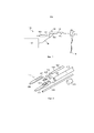
на фиг. 2 проиллюстрирован вид в разобранном состоянии дистального конца электрохирургического инструмента, который является вариантом реализации данного изобретения;in fig. 2 is an exploded view of the distal end of an electrosurgical instrument that is an embodiment of the present invention;
на фиг. 3 проиллюстрирован частично сквозной вид в перспективе дистального конца электрохирургического инструмента, который является вариантом реализации данного изобретения;in fig. 3 illustrates a partially through perspective view of the distal end of an electrosurgical instrument that is an embodiment of the present invention;
на фиг. 4А и 4В проиллюстрирован вид сверху и вид сбоку в поперечном сечении соответственно элемента защитного корпуса, подходящего для использования с данным изобретением; иin fig. 4A and 4B illustrate top and side cross-sectional views, respectively, of a protective housing element suitable for use with the present invention; And
на фиг. 5 проиллюстрирован вид сбоку в поперечном сечении узла дистального наконечника электрохирургического инструмента, который является вариантом реализации данного изобретения.in fig. 5 illustrates a side cross-sectional view of the distal handpiece assembly of an electrosurgical instrument, which is an embodiment of the present invention.
ПОДРОБНОЕ ОПИСАНИЕ СУЩНОСТИ ИЗОБРЕТЕНИЯ; ДОПОЛНИТЕЛЬНЫЕ И ПРЕДПОЧТИТЕЛЬНЫЕ ВАРИАНТЫDETAILED DESCRIPTION OF THE INVENTION; ADDITIONAL AND PREFERRED OPTIONS
Различные аспекты данного изобретения представлены ниже в контексте электрохирургической системы, которая обеспечивает электрохирургический инвазивный инструмент, предназначенный для использования при эндоскопических процедурах для удаления полипов и злокачественных новообразований посредством контролируемой подачи как микроволновой, так и РЧ энергии. Однако следует понимать, что аспекты изобретения, представленные в данном документе, не обязательно должны быть ограничены этим конкретным вариантом применения. Они могут быть в равной степени применимы в вариантах реализации изобретения, в которых требуется только РЧ энергия или в которых требуется только РЧ энергия и подача жидкости.Various aspects of the present invention are presented below in the context of an electrosurgical system that provides an electrosurgical invasive instrument for use in endoscopic procedures to remove polyps and malignancies by controlled delivery of both microwave and RF energy. However, it should be understood that the aspects of the invention presented herein are not necessarily limited to this particular application. They may be equally applicable in embodiments that require only RF energy or that require only RF energy and fluid supply.
На фиг. 1 проиллюстрировано схематическое изображение электрохирургической системы 100 в комплекте, которая способна избирательно подавать на дистальный конец инвазивного электрохирургического инструмента что-либо или все из следующего: РЧ энергии, микроволновой энергии и жидкости, например физиологического раствора или гиалуроновой кислоты. Система 100 содержит генератор 102 для управляемой подачи РЧ электромагнитной (ЭМ) энергии и/или ЭМ энергии микроволновой частоты. Подходящий генератор для этой цели описан в заявке WO 2012/076844, которая включена в данный документе посредством ссылки.In FIG. 1 illustrates a schematic representation of a
Генератор 102 соединен со стыковочным соединением 106 стыковочным кабелем 104. Стыковочное соединение 106 также соединено для приема источника 107 жидкости от устройства 108 для подачи жидкости, такого как шприц. Стыковочное соединение 106 содержит механизм перемещения иглы, который приводится в действие путем скольжения спускового крючка 110. Функция стыковочного соединения 106 состоит в том, чтобы объединять входные отверстия от генератора 102, устройства 108 для подачи жидкости и механизма перемещения иглы в один гибкий стержень 112, который проходит от дистального конца стыковочного соединения 106. Внутренняя конфигурация стыковочного соединения 106 обсуждается более подробно ниже.The
Гибкий стержень 112 могут вводить по всей длине инструментального (рабочего) канала хирургического устройства 114 для осмотра. Блок 116 передачи крутящего момента установлен на проксимальной протяженности стержня 112 между стыковочным соединением 106 и хирургическим устройством 114 для осмотра. Блок 116 передачи крутящего момента входит в зацепление со стержнем, чтобы позволить ему вращаться внутри инструментального канала хирургического устройства 114 для осмотра.The
Гибкий стержень 112 имеет наконечник 118 электрохирургического инструмента, форма которого позволяет ему проходить через инструментальный канал хирургического устройства 114 для осмотра и выступать (например, внутри пациента) на дистальном конце трубки эндоскопа. Наконечник инструмента содержит активный наконечник для подачи РЧ ЭМ энергии и/или ЭМ энергии микроволновой частоты в биологическую ткань и выдвижную иглу для подкожных инъекций для доставки жидкости. Эти объединенные технологии обеспечивают уникальное решение для разреза и удаления нежелательных тканей и возможность заделывания кровеносных сосудов вокруг целевого участка. Благодаря использованию выдвижной иглы для подкожных инъекций хирург может вводить физиологический раствор и/или гиалуроновую кислоту с добавленным маркерным красящим веществом между слоями тканей, чтобы растянуть и отметить положение подлежащего лечению пораженного участка. Инъекция жидкости таким способом поднимает и разделяет слои ткани, облегчая резекцию вокруг пораженного участка и плоскости через подслизистый слой, а также снижая риск прободения стенки кишечника и ненужного термического повреждения мышечного слоя.The
Как более подробно обсуждается ниже, наконечник 118 инструмента дополнительно содержит защитный корпус, расположенный под активным наконечником, чтобы способствовать проведению запланированной резекции ткани, повторно обеспечивая защиту от случайного прободения и жизнеспособность остальной ткани, что, в свою очередь, способствует более быстрому заживлению и восстановлению после операции.As discussed in more detail below, the
Конструкция наконечника инструмента, обсуждаемого ниже, может быть специально разработана для использования с обычным управляемым гибким эндоскопом, содержащим рабочий канал с внутренними диаметрами по меньшей мере 3,3 мм и длиной канала от 60 см до 170 см. Таким образом, большая часть инструмента сравнительно небольшого диаметра (менее 3 мм) находится внутри просвета гораздо большего и преимущественно полимерного изолирующего устройства, то есть гибкого канала эндоскопа, внешний диаметр которого обычно составляет от 11 мм до 13 мм. На практике дистальный узел выступает из дистального конца канала эндоскопа только на 15-25 мм, чтобы не заграждать поле зрения и не воздействовать негативно на фокусировку камеры. Выступающая часть дистального узла - это единственная часть инструмента, которая вообще прямо контактирует с телом пациента.The design of the tip of the instrument discussed below can be specially designed for use with a conventional steerable flexible endoscope containing a working channel with internal diameters of at least 3.3 mm and a channel length of 60 cm to 170 cm. Thus, most of the instrument is relatively small diameter (less than 3 mm) is located within the lumen of a much larger and predominantly polymeric isolation device, i.e. a flexible channel of the endoscope, the outer diameter of which is usually between 11 mm and 13 mm. In practice, the distal node protrudes from the distal end of the endoscope channel only by 15-25 mm, so as not to obstruct the field of view and not adversely affect the focus of the camera. The protruding part of the distal assembly is the only part of the instrument that makes direct contact with the patient's body at all.
На проксимальном конце рабочего канала эндоскопа, который обычно находится на расстоянии 50-80 см от пациента, гибкий стержень 112 выходит из порта рабочего канала и проходит еще на 30-100 см к стыковочному соединению 106. При использовании стыковочное соединение 106 обычно удерживается рукой ассистента в перчатке на протяжении всей процедуры. Стыковочное соединение 106 сконструировано и изготовлено из полимерных материалов таким образом, чтобы обеспечить первичную и вторичную электрическую изоляцию с удлиненным путями утечки и разделительными расстояниями. Стыковочный кабель 104 соединен с генератором 102 с помощью коаксиального интерфейса типа QMA, который предназначен для обеспечения непрерывного вращения по часовой стрелке или против часовой стрелки. Это обеспечивает вращение стыковочного соединения 106 с блоком 116 передачи крутящего момента под управлением пользователя. Ассистент поддерживает стыковочное соединение 106 на протяжении всей процедуры, чтобы помочь пользователю при ответном вращении инструмента, управлении иглой и введении жидкости.At the proximal end of the working channel of the endoscope, which is typically 50-80 cm away from the patient, the
На фиг. 2 проиллюстрирован вид в разобранном состоянии узла 214 дистального конца (иногда называемого наконечником инструмента) электрохирургического инструмента, который является вариантом реализации данного изобретения. Узел 214 дистального конца установлен на дистальном конце внешней трубки 216 канюли гибкого стержня, который, например, соответствует гибкому стержню 112, описанному выше со ссылкой на фиг. 1. Трубка 216 канюли образует гибкую гильзу, определяющую просвет для транспортировки жидкости к наконечнику инструмента, причем наконечник инструмента закреплен на ее дистальном конце. Чтобы обеспечить функцию передачи крутящего момента, внешняя трубка 216 канюли выполнена из оплетенной трубки, например, содержащей оболочку из оплетенной проволоки (например, из нержавеющей стали), заключенную между внутренним в радиальном направлении слоем полимера и внешним в радиальном направлении слоем полимера, причем полимер может, например, представлять собой Pebax®.In FIG. 2 illustrates an exploded view of the distal end assembly 214 (sometimes referred to as the instrument tip) of an electrosurgical instrument that is an embodiment of the present invention. The
В этом варианте реализации изобретения внешняя трубка 216 канюли на своем дистальном конце соединена с трубчатой частью 218 без оплетки, которая может представлять собой гибкий канал. Трубчатая часть 218 может быть образована из любого подходящего полимерного материала, например Pebax® и т.п. Осевая длина (то есть длина, соосная с осью стержня) трубчатой части 218 может составлять 1 мм или больше. Это может обеспечить безопасное расстояние между концом оплетки и проксимальным краем узла 214 дистального конца, чтобы избежать какого-либо риска нагрева оплетки из-за емкостной проводимости при использовании микроволновой энергии. Эта компоновка также может препятствовать замыканию или соединению двух пластин плоской линии передачи или двух проводников в коаксиальной линии передачи.In this embodiment, the
Трубчатая часть 218 может называться «мягким наконечником» 218. В некоторых вариантах реализации изобретения мягкий наконечник 218 может представлять собой дополнительную длину полимерной трубки, которая связана с дистальным концом гильзы или трубки 216 канюли. Для склеивания могут использовать любой подходящий адгезив, например эпоксидный состав и т. п. Опорная трубка 217 может быть установлена над соединением между трубчатой частью 218 и трубкой 216 канюли для усиления соединения путем обеспечения дополнительной механической прочности. Опорная трубка 217 может представлять собой короткую секцию полимерной трубки, внутри которого закреплены как трубчатая часть 218, так и канюля 216, например, с помощью склеивания. Опорная трубка 217 может быть гибкой и/или иметь длину, выбранную для обеспечения того, чтобы она не оказывала неблагоприятное влияние на гибкость стержня.The
Кроме того, соединение трубчатой части 218, трубки 216 канюли и опорной трубки 217 может размещаться в термоусадочной гильзе (не показана), чтобы обеспечить дополнительную конструкционную прочность на дистальном конце стержня. Additionally, the junction of
Оплетка внутри трубки 216 канюли позволяет преобразовать крутящий момент, прилагаемый к проксимальному концу стержня, во вращательное движение наконечника инструмента. Для удобства на некоторых из прилагаемых фигур трубчатая часть 218 и трубка 216 канюли показаны как прозрачные. В практических вариантах реализации изобретения стержень может быть непрозрачным.The braid within the
Дистальный конец трубчатой части 218 выполнен с возможностью надевания на соответствующую проксимальную часть 220 защитного корпуса 222. Защитный корпус изготовлен из металлического материала, имеющего низкое трение с биологической тканью, например из нержавеющей стали, и имеет подходящую форму для выполнения следующих функций:The distal end of the
- установка узла 214 дистального конца на гибком стержне;- installation of the
- обеспечение защитной нижней поверхности для конструкции активного наконечника, которая подает энергию в окружающую биологическую ткань;providing a protective bottom surface for the active tip design that delivers energy to the surrounding biological tissue;
- обеспечение защитного корпуса и опорной рамки для выдвижной иглы; и- providing a protective housing and a support frame for the retractable needle; And
- расположение конструкции активного наконечника относительно коаксиального кабеля во время сборки и последующего использования.- location of the active tip structure relative to the coaxial cable during assembly and subsequent use.
Части конструкции корпуса 222, которые выполняют эти функции, описаны более подробно ниже.The parts of the
Узел 214 дистального конца содержит активный наконечник 224, который представляет собой плоскую часть диэлектрического материала 221 (например, оксида алюминия), содержащего проводящие слои (например, слои металлизации) на своей верхней и нижней поверхностях. Каждый из проводящих слоев электрически соединен соответственно либо с внутренним проводником 228, либо с внешним проводником 226 коаксиального кабеля 142, который подведен в трубке 216 канюли. На дистальном конце коаксиального кабеля 142 его внешняя оболочка удалена, чтобы открыть определенный участок внешнего проводника 226. Внутренний проводник 228 коаксиального кабеля проходит за дистальный конец внешнего проводника 226. Коаксиальный кабель 142 и активный наконечник 224 установлены относительно друг друга таким образом, что выступающая часть внутреннего проводника 228 расположена на первом проводящем слое активного наконечника, и обеспечивается электрическое соединение внешнего проводника 226 со вторым проводящим слоем посредством защитного корпуса 222, как описано ниже. Первый проводящий слой изолирован от внешнего проводника 226, а второй проводящий слой изолирован от внутреннего проводника 228. The
Проводящие слои могут быть сформированы из проводников с высокой температурой плавления, например W или Ti. Однако в одном примере для содействия использованию припоя в электрическом соединении между внутренним и внешним проводниками коаксиального кабеля 142 и активным наконечником 224 проводники с более низкой температурой плавления могут быть нанесены на проксимальные участки проводящих слоев, в которых находятся электрические соединения. Проводники с более низкой температурой плавления могут быть серебряными (Ag) или золотыми (Au).The conductive layers can be formed from high melting point conductors such as W or Ti. However, in one example, to facilitate the use of solder in the electrical connection between the inner and outer conductors of the
Дистальный конец активного наконечника 224 изогнут, чтобы избежать образования острых углов внутри тела пациента. The distal end of the
Внешний проводник 226 электрически соединен с нижним проводящим слоем на нижней стороне активного наконечника 224 посредством защитного корпуса 222. Проксимальный конец защитного корпуса 222 образован с U-образным каналом 248 для приема и поддержки дистального конца коаксиального кабеля 142 питания. Узел дистального конца выполнен таким образом, что открытая часть внешнего проводника 226 находится в U-образном канале 248. Электропроводящий элемент 230, такой как гильза или муфта, используется для обжатия открытой части внешнего проводника 226. Сжатие, вызванное обжатием, означает, что коаксиальный кабель деформируется в области, где он принимается защитным корпусом 222. Например, часть коаксиального кабеля, в которой внешний проводник 226 открыт, может иметь овальное поперечное сечение, благодаря чему он упирается в стороны U-образного канала 248 и образует с ними прочный электрический контакт. Таким образом, обжатый внешний проводник 226 может удерживаться корпусом посредством посадки с натягом.The
Для осуществления электрического соединения между внешним проводником 226 и нижним проводящим слоем 229 на активном наконечнике 224 защитный корпус 222 электрически соединен с нижним проводящим слоем, например, пайкой (см., например, фиг. 5). В этом варианте реализации изобретения для этой цели предусмотрен навесок 231 припоя. Навесок 231 припоя имеет такую форму, чтобы его можно было принимать в углублении 249, образованном в верхней поверхности защитного корпуса 222. В этом примере углубление 49 является прямоугольным, и навесок 231 припоя имеет соответствующую форму, но может использоваться любая подходящая форма. Углубление 249 имеет отступ от краев защитного корпуса таким образом, чтобы припой присутствовал только между нижней поверхностью активного наконечника 224 и защитным корпусом 222, то есть он не течет к боковым краям активного наконечника 224. В сборке навесок 231 припоя может быть совмещен с областью на нижней поверхности активного наконечника 224, которая покрыта проводником с более низкой температурой плавления, как обсуждалось выше (например, золото). Навеском припоя может быть обеспечен подходящий изгиб (не показан) при сборке компонентов, чтобы облегчить процесс пайки. Сам процесс пайки может быть индукционной пайкой. Эффект индукционной пайки может быть ограничен областью активного наконечника 224 и защитного корпуса 222 на навеске 231 припоя.In order to make an electrical connection between the
Вышеуказанная конфигурация является предпочтительной, поскольку защитный корпус 222 удерживает все следующие элементы: (i) активный наконечник 224, (ii) навесок 231 припоя и (iii) коаксиальный кабель 142 в фиксированной пространственной взаимосвязи, которая обеспечивает точную и повторяемую сборку.The above configuration is preferred because the
Узел дистального конца дополнительно содержит направляющую 232 иглы, которая удерживается в углублении, образованном в нижней поверхности защитного корпуса 222. Направляющая 232 иглы представляет собой полую трубку (например, наконечник), например, изготовленную из полиимида, внутри которой установлена с возможностью скольжения игла 234 для подкожных инъекций. Игла 234 находится в жидкостной связи с внутренним объемом трубки 216 канюли, чтобы принимать находящуюся в ней жидкость для доставки к месту обработки.The distal end assembly further comprises a
После того как сборка 214 дистального конца собрана, она может быть закреплена внутри дистального конца трубчатой части 218 с помощью посадки с натягом и адгезива (например, эпоксидного средства). Адгезив также может образовывать заглушку для дистального конца трубчатой части 218, чтобы обеспечить герметичное уплотнение, а это означает, что жидкость, вводимая в стыковочное соединение, выходит только через иглу 234. Аналогичным образом, соединение (например, паяное соединение) между внутренним проводником 228 и верхним проводящим слоем 227 может иметь защитное покрытие 251 (см. фиг. 5), которое может быть образовано из подходящего адгезива (например, эпоксидного средства). Защитное покрытие 251 может усиливать соединение между защитным корпусом 222 и активным наконечником 224, в то же время образуя концевую заглушку для трубчатой части 218, то есть герметичное уплотнение, а это означает, что жидкость, вводимая в стыковочное соединение, выходит только через иглу.Once the
При использовании активный наконечник 224 находится в тесном контакте с телом пациента. Игла 234 может проходить за дистальный конец активного наконечника 224 и может быть отведена назад до положения внутри направляющей трубки 232 посредством управления скользящим механизмом на стыковочном соединении, который воздействует на провод 235 управления (см. фиг. 3) для размещения и втягивания иглы 234. В выдвинутом положении иглу используют для ввода жидкости с целью локального растягивания и/или маркировки ткани. Проводящие слои на активном наконечнике 224 образуют биполярные электроды для подачи РЧ и/или микроволновой электромагнитной энергии. In use, the
Направляющая 232 иглы проходит обратно внутрь и проксимально к дистальному узлу, чтобы обеспечить увеличенный зазор утечки, чтобы гарантировать, что РЧ/микроволновая энергия подается только через область дистального наконечника активного наконечника 224.The
На фиг. 3 проиллюстрирован узел 214 дистального конца в собранной конфигурации. Трубчатая часть 218, опорная гильза 217 и трубка 216 канюли показаны прозрачными, так что видны внутренние компоненты. Части защитного корпуса 222 внутри трубчатой части 218 опущены, чтобы показать, как электропроводящий элемент 230 насаживают на внешний проводник 226.In FIG. 3 illustrates the
На фиг. 4А и 4В показана форма конструкции 222 защитного корпуса, которую можно использовать в вариантах реализации данного изобретения. Дистальный конец защитного корпуса 222 имеет плоскую верхнюю поверхность 250 для контакта с нижним проводящим слоем 229 на активном наконечнике 224. Как обсуждалось выше, прямоугольное углубление 249 сформировано по направлению к проксимальному концу плоской верхней поверхности 250 для приема навески 231 припоя.In FIG. 4A and 4B show a form of
Проксимальный конец защитного корпуса 222 образован с U-образным каналом 248 для приема и поддержки дистального конца коаксиального кабеля 142 питания. Аналогичный канал образован на нижней стороне проксимального конца защитного корпуса 222 для приема направляющей трубки 232 выдвижной иглы 234. Внешняя поверхность проксимального конца защитного корпуса 222 имеет цилиндрическую форму, диаметр которой выбирается так, чтобы входить внутрь дистального конца трубчатой части 218.The proximal end of the
На сторонах защитного корпуса 222 между проксимальным и дистальным концами имеется пара выступающих частей 244 выступа, внутренние поверхности которых входят в зацепление с соответствующими боковыми краями активного наконечника 224 и внешняя поверхность которых входит в зацепление с помощью посадки с натягом с внутренней поверхностью трубчатой части 218.On the sides of the
Защитный корпус 222 предпочтительно выполнен из металлического материала, имеющего низкий коэффициент трения с биологической тканью, такого как нержавеющая сталь.The
Дистальный конец корпуса имеет форму, позволяющую активному наконечнику 224 нависать над ним примерно на 0,2 мм вокруг дистального края, за исключением дистального наконечника. Следовательно, поверхность, которая контактирует с нижней стороной активного наконечника, имеет максимальную ширину 2 мм, которая сужается до 1,6 мм в промежуточной части 223, а затем сужается к дистальному наконечнику в дистальной части 225. Дистальный наконечник может представлять собой одну закругленную кривую, например, с радиусом 0,2 мм.The distal end of the body is shaped to allow the
Между тем проксимальный конец корпуса определяет продолговатое углубление для приема проксимального конца активного наконечника. Продолговатое углубление ограничено с каждой стороны парой выступов 244, которые служат для удержания и выравнивания активного наконечника, а также определяют объем для приема защитного корпуса 251, который закрывает открытый внутренний проводник 228 коаксиального кабеля 142.Meanwhile, the proximal end of the housing defines an elongated recess for receiving the proximal end of the active tip. The elongated recess is defined on each side by a pair of
На фиг. 5 проиллюстрирован вид в поперечном сечении узла 214 дистального конца при полной сборке. Признаки, описанные выше, обозначены одинаковыми ссылочными позициями. В этих графических материалах показано, что паяное проводящее соединение, обеспечиваемое навеском 231 припоя, находится между защитным корпусом 222 и нижним проводящим слоем 229. Чтобы обеспечить надежное соединение между защитным корпусом 222 и активным наконечником 224, нижний проводящий слой 229 может быть связан с плоской поверхностью 250, к которой он дистально примыкает от зоны пайки.In FIG. 5 illustrates a cross-sectional view of the
Claims (27)
Applications Claiming Priority (3)
| Application Number | Priority Date | Filing Date | Title |
|---|---|---|---|
| GB1713177.2A GB2565575A (en) | 2017-08-17 | 2017-08-17 | Electrosurgical apparatus for delivering RF and/or microwave energy into biological tissue |
| GB1713177.2 | 2017-08-17 | ||
| PCT/EP2018/072155 WO2019034710A1 (en) | 2017-08-17 | 2018-08-15 | Electrosurgical apparatus for delivering rf and/or microwave energy into biological tissue |
Related Child Applications (1)
| Application Number | Title | Priority Date | Filing Date |
|---|---|---|---|
| RU2022107317A Division RU2022107317A (en) | 2017-08-17 | 2018-08-15 | ELECTROSURGICAL DEVICE FOR SUPPLYING RADIO-FREQUENCY AND/OR MICROWAVE ENERGY TO BIOLOGICAL TISSUE |
Publications (3)
| Publication Number | Publication Date |
|---|---|
| RU2020106129A RU2020106129A (en) | 2021-09-17 |
| RU2020106129A3 RU2020106129A3 (en) | 2021-09-30 |
| RU2768604C2 true RU2768604C2 (en) | 2022-03-24 |
Family
ID=59996698
Family Applications (1)
| Application Number | Title | Priority Date | Filing Date |
|---|---|---|---|
| RU2020106129A RU2768604C2 (en) | 2017-08-17 | 2018-08-15 | Electrosurgical device for supplying radio-frequency energy and/or microwave energy to biological tissue |
Country Status (15)
| Country | Link |
|---|---|
| US (1) | US20200268445A1 (en) |
| EP (2) | EP3668434B1 (en) |
| JP (1) | JP7195623B2 (en) |
| KR (1) | KR20200042442A (en) |
| CN (1) | CN110799143B (en) |
| AU (1) | AU2018316496A1 (en) |
| BR (1) | BR112019027335A2 (en) |
| CA (1) | CA3067514A1 (en) |
| ES (2) | ES2921436T3 (en) |
| GB (1) | GB2565575A (en) |
| IL (1) | IL271526A (en) |
| PT (1) | PT3782570T (en) |
| RU (1) | RU2768604C2 (en) |
| SG (2) | SG10202112729VA (en) |
| WO (1) | WO2019034710A1 (en) |
Families Citing this family (4)
| Publication number | Priority date | Publication date | Assignee | Title |
|---|---|---|---|---|
| ES2953573T3 (en) * | 2018-12-27 | 2023-11-14 | Conmed Corp | Soft Thread Cannula and Cannula Sealing Gasket Assembly |
| US11766288B2 (en) | 2019-02-22 | 2023-09-26 | Gyrus Acmi, Inc. | Flexible bipolar sheath |
| US11717342B2 (en) | 2019-04-11 | 2023-08-08 | Gyrus Acmi, Inc. | Medical device |
| GB2597751A (en) | 2020-08-03 | 2022-02-09 | Creo Medical Ltd | Electrosurgical apparatus, and methods for cutting and coagulation |
Citations (6)
| Publication number | Priority date | Publication date | Assignee | Title |
|---|---|---|---|---|
| RU2466758C1 (en) * | 2011-06-06 | 2012-11-20 | Государственное образовательное учреждение высшего профессионального образования "Саратовский государственный технический университет" (СГТУ) | Contact microwave applicator |
| US20150196353A1 (en) * | 2012-07-03 | 2015-07-16 | Creo Medical Limited | Electrosurgical resection instrument |
| RU2562287C2 (en) * | 2009-11-17 | 2015-09-10 | БиЭсДи МЕДИКАЛ КОРПОРЕЙШН | Applicator and microwave coagulation system |
| US20170118806A1 (en) * | 2012-03-31 | 2017-04-27 | Microcube, Llc | Returned power for microwave applications |
| WO2017075067A1 (en) * | 2015-10-26 | 2017-05-04 | Neuwave Medical, Inc. | Energy delivery systems and uses thereof |
| WO2017105799A1 (en) * | 2015-12-14 | 2017-06-22 | The Climate Corporation | Generating digital models of relative yield of a crop based on nitrate values in the soil |
Family Cites Families (11)
| Publication number | Priority date | Publication date | Assignee | Title |
|---|---|---|---|---|
| US6210396B1 (en) * | 1999-06-24 | 2001-04-03 | Medtronic, Inc. | Guiding catheter with tungsten loaded band |
| JP3482379B2 (en) * | 1999-07-08 | 2003-12-22 | オリンパス株式会社 | High frequency knife for endoscope |
| US6878147B2 (en) * | 2001-11-02 | 2005-04-12 | Vivant Medical, Inc. | High-strength microwave antenna assemblies |
| GB0130975D0 (en) * | 2001-12-27 | 2002-02-13 | Gyrus Group Plc | A surgical instrument |
| GB0620058D0 (en) * | 2006-10-10 | 2006-11-22 | Medical Device Innovations Ltd | Tissue measurement and ablation antenna |
| US8328801B2 (en) * | 2009-08-17 | 2012-12-11 | Vivant Medical, Inc. | Surface ablation antenna with dielectric loading |
| US8906007B2 (en) * | 2009-09-28 | 2014-12-09 | Covidien Lp | Electrosurgical devices, directional reflector assemblies coupleable thereto, and electrosurgical systems including same |
| GB201021032D0 (en) | 2010-12-10 | 2011-01-26 | Creo Medical Ltd | Electrosurgical apparatus |
| EP2997922B1 (en) * | 2012-09-26 | 2017-12-20 | Aesculap AG | Apparatus for tissue cutting and sealing |
| GB2514100B (en) * | 2013-05-08 | 2020-04-01 | Creo Medical Ltd | Apparatus for Controlling Power Delivered by Electrosurgical Probe |
| GB201323171D0 (en) * | 2013-12-31 | 2014-02-12 | Creo Medical Ltd | Electrosurgical apparatus and device |
-
2017
- 2017-08-17 GB GB1713177.2A patent/GB2565575A/en not_active Withdrawn
-
2018
- 2018-08-15 SG SG10202112729VA patent/SG10202112729VA/en unknown
- 2018-08-15 CN CN201880043868.6A patent/CN110799143B/en active Active
- 2018-08-15 EP EP18759585.5A patent/EP3668434B1/en active Active
- 2018-08-15 BR BR112019027335-2A patent/BR112019027335A2/en unknown
- 2018-08-15 WO PCT/EP2018/072155 patent/WO2019034710A1/en unknown
- 2018-08-15 JP JP2019570407A patent/JP7195623B2/en active Active
- 2018-08-15 AU AU2018316496A patent/AU2018316496A1/en not_active Abandoned
- 2018-08-15 CA CA3067514A patent/CA3067514A1/en active Pending
- 2018-08-15 ES ES20193995T patent/ES2921436T3/en active Active
- 2018-08-15 RU RU2020106129A patent/RU2768604C2/en active
- 2018-08-15 US US16/624,742 patent/US20200268445A1/en active Pending
- 2018-08-15 ES ES18759585T patent/ES2931298T3/en active Active
- 2018-08-15 EP EP20193995.6A patent/EP3782570B1/en active Active
- 2018-08-15 SG SG11201912234RA patent/SG11201912234RA/en unknown
- 2018-08-15 KR KR1020197037687A patent/KR20200042442A/en not_active Application Discontinuation
- 2018-08-15 PT PT201939956T patent/PT3782570T/en unknown
-
2019
- 2019-12-18 IL IL271526A patent/IL271526A/en unknown
Patent Citations (6)
| Publication number | Priority date | Publication date | Assignee | Title |
|---|---|---|---|---|
| RU2562287C2 (en) * | 2009-11-17 | 2015-09-10 | БиЭсДи МЕДИКАЛ КОРПОРЕЙШН | Applicator and microwave coagulation system |
| RU2466758C1 (en) * | 2011-06-06 | 2012-11-20 | Государственное образовательное учреждение высшего профессионального образования "Саратовский государственный технический университет" (СГТУ) | Contact microwave applicator |
| US20170118806A1 (en) * | 2012-03-31 | 2017-04-27 | Microcube, Llc | Returned power for microwave applications |
| US20150196353A1 (en) * | 2012-07-03 | 2015-07-16 | Creo Medical Limited | Electrosurgical resection instrument |
| WO2017075067A1 (en) * | 2015-10-26 | 2017-05-04 | Neuwave Medical, Inc. | Energy delivery systems and uses thereof |
| WO2017105799A1 (en) * | 2015-12-14 | 2017-06-22 | The Climate Corporation | Generating digital models of relative yield of a crop based on nitrate values in the soil |
Also Published As
| Publication number | Publication date |
|---|---|
| EP3668434B1 (en) | 2022-09-28 |
| EP3668434A1 (en) | 2020-06-24 |
| GB201713177D0 (en) | 2017-10-04 |
| EP3782570B1 (en) | 2022-04-27 |
| JP2020531055A (en) | 2020-11-05 |
| KR20200042442A (en) | 2020-04-23 |
| JP7195623B2 (en) | 2022-12-26 |
| CA3067514A1 (en) | 2019-02-21 |
| ES2931298T3 (en) | 2022-12-28 |
| EP3782570A1 (en) | 2021-02-24 |
| ES2921436T3 (en) | 2022-08-25 |
| CN110799143B (en) | 2022-12-23 |
| GB2565575A (en) | 2019-02-20 |
| RU2020106129A (en) | 2021-09-17 |
| SG10202112729VA (en) | 2021-12-30 |
| AU2018316496A1 (en) | 2020-01-23 |
| CN110799143A (en) | 2020-02-14 |
| SG11201912234RA (en) | 2020-01-30 |
| RU2020106129A3 (en) | 2021-09-30 |
| BR112019027335A2 (en) | 2020-07-07 |
| JP2023027197A (en) | 2023-03-01 |
| WO2019034710A1 (en) | 2019-02-21 |
| IL271526A (en) | 2020-02-27 |
| US20200268445A1 (en) | 2020-08-27 |
| PT3782570T (en) | 2022-07-07 |
Similar Documents
| Publication | Publication Date | Title |
|---|---|---|
| JP6803902B2 (en) | Electrosurgical equipment that supplies RF and / or microwave energy into living tissue | |
| JP6225181B2 (en) | Electrosurgical resection instrument | |
| RU2768604C2 (en) | Electrosurgical device for supplying radio-frequency energy and/or microwave energy to biological tissue | |
| JP7261492B2 (en) | electrosurgical device | |
| JP2021509594A (en) | Electrosurgical ablation instrument | |
| CN113164202A (en) | Electrosurgical instrument | |
| JP7469824B2 (en) | Electrosurgical device for delivering RF and/or microwave energy into biological tissue - Patents.com | |
| CN115802968A (en) | Electrosurgical device for cutting and coagulation |