RU2768375C1 - Dynamic image decoding device, a dynamic image decoding method, a dynamic image decoding program, a dynamic image encoding device, a dynamic image encoding method and a dynamic image encoding program - Google Patents
Dynamic image decoding device, a dynamic image decoding method, a dynamic image decoding program, a dynamic image encoding device, a dynamic image encoding method and a dynamic image encoding program Download PDFInfo
- Publication number
- RU2768375C1 RU2768375C1 RU2021121169A RU2021121169A RU2768375C1 RU 2768375 C1 RU2768375 C1 RU 2768375C1 RU 2021121169 A RU2021121169 A RU 2021121169A RU 2021121169 A RU2021121169 A RU 2021121169A RU 2768375 C1 RU2768375 C1 RU 2768375C1
- Authority
- RU
- Russia
- Prior art keywords
- motion vector
- prediction
- candidate
- motion information
- vector predictor
- Prior art date
Links
Images


Classifications
-
- H—ELECTRICITY
- H04—ELECTRIC COMMUNICATION TECHNIQUE
- H04N—PICTORIAL COMMUNICATION, e.g. TELEVISION
- H04N19/00—Methods or arrangements for coding, decoding, compressing or decompressing digital video signals
- H04N19/10—Methods or arrangements for coding, decoding, compressing or decompressing digital video signals using adaptive coding
- H04N19/102—Methods or arrangements for coding, decoding, compressing or decompressing digital video signals using adaptive coding characterised by the element, parameter or selection affected or controlled by the adaptive coding
- H04N19/103—Selection of coding mode or of prediction mode
-
- H—ELECTRICITY
- H04—ELECTRIC COMMUNICATION TECHNIQUE
- H04N—PICTORIAL COMMUNICATION, e.g. TELEVISION
- H04N19/00—Methods or arrangements for coding, decoding, compressing or decompressing digital video signals
- H04N19/50—Methods or arrangements for coding, decoding, compressing or decompressing digital video signals using predictive coding
- H04N19/503—Methods or arrangements for coding, decoding, compressing or decompressing digital video signals using predictive coding involving temporal prediction
- H04N19/51—Motion estimation or motion compensation
- H04N19/513—Processing of motion vectors
- H04N19/517—Processing of motion vectors by encoding
- H04N19/52—Processing of motion vectors by encoding by predictive encoding
-
- H—ELECTRICITY
- H04—ELECTRIC COMMUNICATION TECHNIQUE
- H04N—PICTORIAL COMMUNICATION, e.g. TELEVISION
- H04N19/00—Methods or arrangements for coding, decoding, compressing or decompressing digital video signals
- H04N19/10—Methods or arrangements for coding, decoding, compressing or decompressing digital video signals using adaptive coding
- H04N19/102—Methods or arrangements for coding, decoding, compressing or decompressing digital video signals using adaptive coding characterised by the element, parameter or selection affected or controlled by the adaptive coding
- H04N19/103—Selection of coding mode or of prediction mode
- H04N19/107—Selection of coding mode or of prediction mode between spatial and temporal predictive coding, e.g. picture refresh
-
- H—ELECTRICITY
- H04—ELECTRIC COMMUNICATION TECHNIQUE
- H04N—PICTORIAL COMMUNICATION, e.g. TELEVISION
- H04N19/00—Methods or arrangements for coding, decoding, compressing or decompressing digital video signals
- H04N19/10—Methods or arrangements for coding, decoding, compressing or decompressing digital video signals using adaptive coding
- H04N19/134—Methods or arrangements for coding, decoding, compressing or decompressing digital video signals using adaptive coding characterised by the element, parameter or criterion affecting or controlling the adaptive coding
- H04N19/136—Incoming video signal characteristics or properties
- H04N19/137—Motion inside a coding unit, e.g. average field, frame or block difference
- H04N19/139—Analysis of motion vectors, e.g. their magnitude, direction, variance or reliability
-
- H—ELECTRICITY
- H04—ELECTRIC COMMUNICATION TECHNIQUE
- H04N—PICTORIAL COMMUNICATION, e.g. TELEVISION
- H04N19/00—Methods or arrangements for coding, decoding, compressing or decompressing digital video signals
- H04N19/10—Methods or arrangements for coding, decoding, compressing or decompressing digital video signals using adaptive coding
- H04N19/102—Methods or arrangements for coding, decoding, compressing or decompressing digital video signals using adaptive coding characterised by the element, parameter or selection affected or controlled by the adaptive coding
- H04N19/103—Selection of coding mode or of prediction mode
- H04N19/105—Selection of the reference unit for prediction within a chosen coding or prediction mode, e.g. adaptive choice of position and number of pixels used for prediction
-
- H—ELECTRICITY
- H04—ELECTRIC COMMUNICATION TECHNIQUE
- H04N—PICTORIAL COMMUNICATION, e.g. TELEVISION
- H04N19/00—Methods or arrangements for coding, decoding, compressing or decompressing digital video signals
- H04N19/10—Methods or arrangements for coding, decoding, compressing or decompressing digital video signals using adaptive coding
- H04N19/102—Methods or arrangements for coding, decoding, compressing or decompressing digital video signals using adaptive coding characterised by the element, parameter or selection affected or controlled by the adaptive coding
- H04N19/119—Adaptive subdivision aspects, e.g. subdivision of a picture into rectangular or non-rectangular coding blocks
-
- H—ELECTRICITY
- H04—ELECTRIC COMMUNICATION TECHNIQUE
- H04N—PICTORIAL COMMUNICATION, e.g. TELEVISION
- H04N19/00—Methods or arrangements for coding, decoding, compressing or decompressing digital video signals
- H04N19/10—Methods or arrangements for coding, decoding, compressing or decompressing digital video signals using adaptive coding
- H04N19/134—Methods or arrangements for coding, decoding, compressing or decompressing digital video signals using adaptive coding characterised by the element, parameter or criterion affecting or controlling the adaptive coding
- H04N19/136—Incoming video signal characteristics or properties
- H04N19/137—Motion inside a coding unit, e.g. average field, frame or block difference
-
- H—ELECTRICITY
- H04—ELECTRIC COMMUNICATION TECHNIQUE
- H04N—PICTORIAL COMMUNICATION, e.g. TELEVISION
- H04N19/00—Methods or arrangements for coding, decoding, compressing or decompressing digital video signals
- H04N19/10—Methods or arrangements for coding, decoding, compressing or decompressing digital video signals using adaptive coding
- H04N19/169—Methods or arrangements for coding, decoding, compressing or decompressing digital video signals using adaptive coding characterised by the coding unit, i.e. the structural portion or semantic portion of the video signal being the object or the subject of the adaptive coding
- H04N19/17—Methods or arrangements for coding, decoding, compressing or decompressing digital video signals using adaptive coding characterised by the coding unit, i.e. the structural portion or semantic portion of the video signal being the object or the subject of the adaptive coding the unit being an image region, e.g. an object
- H04N19/176—Methods or arrangements for coding, decoding, compressing or decompressing digital video signals using adaptive coding characterised by the coding unit, i.e. the structural portion or semantic portion of the video signal being the object or the subject of the adaptive coding the unit being an image region, e.g. an object the region being a block, e.g. a macroblock
-
- H—ELECTRICITY
- H04—ELECTRIC COMMUNICATION TECHNIQUE
- H04N—PICTORIAL COMMUNICATION, e.g. TELEVISION
- H04N19/00—Methods or arrangements for coding, decoding, compressing or decompressing digital video signals
- H04N19/42—Methods or arrangements for coding, decoding, compressing or decompressing digital video signals characterised by implementation details or hardware specially adapted for video compression or decompression, e.g. dedicated software implementation
- H04N19/423—Methods or arrangements for coding, decoding, compressing or decompressing digital video signals characterised by implementation details or hardware specially adapted for video compression or decompression, e.g. dedicated software implementation characterised by memory arrangements
-
- H—ELECTRICITY
- H04—ELECTRIC COMMUNICATION TECHNIQUE
- H04N—PICTORIAL COMMUNICATION, e.g. TELEVISION
- H04N19/00—Methods or arrangements for coding, decoding, compressing or decompressing digital video signals
- H04N19/44—Decoders specially adapted therefor, e.g. video decoders which are asymmetric with respect to the encoder
-
- H—ELECTRICITY
- H04—ELECTRIC COMMUNICATION TECHNIQUE
- H04N—PICTORIAL COMMUNICATION, e.g. TELEVISION
- H04N19/00—Methods or arrangements for coding, decoding, compressing or decompressing digital video signals
- H04N19/50—Methods or arrangements for coding, decoding, compressing or decompressing digital video signals using predictive coding
- H04N19/503—Methods or arrangements for coding, decoding, compressing or decompressing digital video signals using predictive coding involving temporal prediction
- H04N19/51—Motion estimation or motion compensation
- H04N19/513—Processing of motion vectors
-
- H—ELECTRICITY
- H04—ELECTRIC COMMUNICATION TECHNIQUE
- H04N—PICTORIAL COMMUNICATION, e.g. TELEVISION
- H04N19/00—Methods or arrangements for coding, decoding, compressing or decompressing digital video signals
- H04N19/70—Methods or arrangements for coding, decoding, compressing or decompressing digital video signals characterised by syntax aspects related to video coding, e.g. related to compression standards
Abstract
Description
Область техники, к которой относится изобретениеThe field of technology to which the invention belongs
[0001] Настоящее изобретение относится к технологии кодирования и декодирования кадров для разделения кадра на блоки и выполнения предсказания.[0001] The present invention relates to a frame encoding and decoding technology for dividing a frame into blocks and performing prediction.
Уровень техникиState of the art
[0002] При кодировании и декодировании кадров, целевой кадр разделяется на блоки, каждый из которых представляет собой набор из предписанного количества дискретных отсчетов, и процесс выполняется в единицах блоков. Эффективность кодирования повышается посредством разделения кадра на соответствующие блоки и надлежащего задания внутрикадрового предсказания (интра-предсказания) и межкадрового предсказания (интер-предсказания).[0002] When encoding and decoding frames, the target frame is divided into blocks, each of which is a set of a prescribed number of discrete samples, and the process is performed in units of blocks. Encoding efficiency is improved by dividing the frame into appropriate blocks and properly specifying intra-prediction (intra-prediction) and inter-prediction (inter-prediction).
[0003] При кодировании/декодировании движущихся кадров, эффективность кодирования повышается посредством интер-предсказания для выполнения предсказания из кодированного/декодированного кадра. Патентный документ 1 описывает технологию для применения аффинного преобразования во время интер-предсказания. Довольно часто объект вызывает деформацию, такую как увеличение/уменьшение и вращение в движущихся кадрах, и эффективное кодирование обеспечивается за счет применения технологии патентного документа 1.[0003] When encoding/decoding moving frames, encoding efficiency is improved by inter-prediction to perform prediction from an encoded/decoded frame.
Список библиографических ссылокList of bibliographic references
Патентные документыPatent Documents
[0004] Патентный документ 1[0004]
Не прошедшая экспертизу заявка на патент (Япония), первая публикация № H9-172644.Unexamined Patent Application (Japan), First Publication No. H9-172644.
Сущность изобретенияThe essence of the invention
Техническая задачаTechnical task
[0005] Тем не менее, поскольку технология патентного документа 1 заключает в себе преобразование кадров, имеется проблема в том, что нагрузка по обработке является большой. С учетом вышеизложенной проблемы, настоящее изобретение предоставляет эффективную технологию кодирования с низкой нагрузкой.[0005] However, since the technology of
Решение задачиThe solution of the problem
[0006][0006]
Чтобы разрешать вышеописанные проблемы, устройство декодирования движущихся кадров согласно аспекту настоящего изобретения включает в себя модуль извлечения потенциально подходящих вариантов пространственной информации движения, выполненный с возможностью извлекать потенциально подходящий вариант пространственной информации движения из информации движения блока, соседнего с целевым блоком декодирования, в пространственной области; модуль извлечения потенциально подходящих вариантов временной информации движения, выполненный с возможностью извлекать потенциально подходящий вариант временной информации движения из информации движения блока, соседнего с целевым блоком декодирования, во временной области; и модуль извлечения потенциально подходящих вариантов информации движения на основе предыстории, выполненный с возможностью извлекать потенциально подходящий вариант информации движения на основе предыстории из запоминающего устройства для хранения информации движения декодированного блока, при этом потенциально подходящий вариант временной информации движения не сравнивается ни с потенциально подходящим вариантом пространственной информации движения, ни с потенциально подходящим вариантом информации движения на основе предыстории относительно информации движения.In order to solve the above-described problems, a moving frame decoding apparatus according to an aspect of the present invention includes a spatial motion information potential candidate extractor configured to extract a spatial motion information candidate from motion information of a block adjacent to a decoding target block in a spatial domain; a candidate temporal motion information candidate extractor, configured to extract a candidate temporal motion information from the motion information of a block adjacent to the decoding target block in the time domain; and a history-based motion information candidate extractor, configured to extract the motion information candidate based on the history from the motion information storage device of the decoded block, wherein the temporal motion information candidate is not compared with either the spatial motion information candidate. motion information, nor with a potentially suitable motion information based on a history of the motion information.
[0007][0007]
Кроме того, способ декодирования движущихся кадров согласно другому аспекту настоящего изобретения включает в себя этапы: извлечения потенциально подходящего варианта пространственной информации движения из информации движения блока, соседнего с целевым блоком декодирования, в пространственной области; извлечения потенциально подходящего варианта временной информации движения из информации движения блока, соседнего с целевым блоком декодирования, во временной области; и извлечения потенциально подходящего варианта информации движения на основе предыстории из запоминающего устройства для хранения информации движения декодированного блока, при этом потенциально подходящий вариант временной информации движения не сравнивается ни с потенциально подходящим вариантом пространственной информации движения, ни с потенциально подходящим вариантом информации движения на основе предыстории относительно информации движения.In addition, a moving frame decoding method according to another aspect of the present invention includes the steps of: extracting a potentially suitable case of spatial motion information from motion information of a block adjacent to a decoding target block in a spatial domain; extracting a potentially suitable case of temporal motion information from the motion information of a block adjacent to the decoding target block in the time domain; and extracting the motion information candidate based on the history from the motion information storage device of the decoded block, wherein the candidate temporal motion information is compared with neither the candidate spatial motion information nor the candidate motion information based on the history with respect to motion information.
[0008][0008]
Кроме того, программа для декодирования движущихся кадров согласно другому аспекту настоящего изобретения предписывает компьютеру выполнять этапы: извлечения потенциально подходящего варианта пространственной информации движения из информации движения блока, соседнего с целевым блоком декодирования, в пространственной области; извлечения потенциально подходящего варианта временной информации движения из информации движения блока, соседнего с целевым блоком декодирования, во временной области; и извлечения потенциально подходящего варианта информации движения на основе предыстории из запоминающего устройства для хранения информации движения декодированного блока, при этом потенциально подходящий вариант временной информации движения не сравнивается ни с потенциально подходящим вариантом пространственной информации движения, ни с потенциально подходящим вариантом информации движения на основе предыстории относительно информации движения.In addition, a program for decoding moving frames according to another aspect of the present invention causes a computer to perform the steps of: extracting a potentially suitable case of spatial motion information from the motion information of a block adjacent to a decoding target block in a spatial domain; extracting a potentially suitable case of temporal motion information from the motion information of a block adjacent to the decoding target block in the time domain; and extracting the motion information candidate based on the history from the motion information storage device of the decoded block, wherein the candidate temporal motion information is compared with neither the candidate spatial motion information nor the candidate motion information based on the history with respect to motion information.
Преимущества изобретенияBenefits of the Invention
[0009] Согласно настоящему изобретению, можно реализовывать высокоэффективный процесс кодирования/декодирования кадров с низкой нагрузкой.[0009] According to the present invention, it is possible to realize a highly efficient frame encoding/decoding process with low load.
Краткое описание чертежейBrief description of the drawings
[0010] Фиг. 1 является блок-схемой устройства кодирования кадров согласно варианту осуществления настоящего изобретения.[0010] FIG. 1 is a block diagram of a frame encoding apparatus according to an embodiment of the present invention.
Фиг. 2 является блок-схемой устройства декодирования кадров согласно варианту осуществления настоящего изобретения.Fig. 2 is a block diagram of a frame decoding apparatus according to an embodiment of the present invention.
Фиг. 3 является пояснительной блок-схемой последовательности операций способа, показывающей операцию разделения древовидного блока.Fig. 3 is an explanatory flowchart showing a tree block splitting operation.
Фиг. 4 является схемой, показывающей состояние, в котором входной кадр разделяется на древовидные блоки.Fig. 4 is a diagram showing a state in which an input frame is divided into tree blocks.
Фиг. 5 является пояснительной схемой, показывающей Z-сканирование.Fig. 5 is an explanatory diagram showing a Z-scan.
Фиг. 6A является схемой, показывающей разделенную форму блока.Fig. 6A is a diagram showing a divided block shape.
Фиг. 6B является схемой, показывающей разделенную форму блока.Fig. 6B is a diagram showing a divided block shape.
Фиг. 6C является схемой, показывающей разделенную форму блока.Fig. 6C is a diagram showing a divided block shape.
Фиг. 6D является схемой, показывающей разделенную форму блока.Fig. 6D is a diagram showing a divided block shape.
Фиг. 6E является схемой, показывающей разделенную форму блока.Fig. 6E is a diagram showing a divided block shape.
Фиг. 7 является пояснительной блок-схемой последовательности операций способа, показывающей операцию разделения блока на четыре части.Fig. 7 is an explanatory flowchart showing an operation of dividing a block into four parts.
Фиг. 8 является пояснительной блок-схемой последовательности операций способа, показывающей операцию разделения блока на две или три части.Fig. 8 is an explanatory flowchart showing the operation of dividing a block into two or three parts.
Фиг. 9 является синтаксисом для выражения формы разбиения блоков.Fig. 9 is the syntax for expressing the block split shape.
Фиг. 10A является пояснительной схемой, показывающей интра-предсказание.Fig. 10A is an explanatory diagram showing intra prediction.
Фиг. 10B является пояснительной схемой, показывающей интра-предсказание.Fig. 10B is an explanatory diagram showing intra prediction.
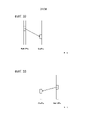
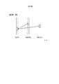
Фиг. 11 является пояснительной схемой, показывающей опорный блок интер-предсказания.Fig. 11 is an explanatory diagram showing an inter prediction reference block.
Фиг. 12 является синтаксисом для выражения режима предсказания блоков кодирования.Fig. 12 is a syntax for expressing a coding block prediction mode.
Фиг. 13 является схемой, показывающей соответствие между синтаксическим элементом, связанным со интер-предсказанием, и режимом.Fig. 13 is a diagram showing a correspondence between a syntax element related to inter prediction and a mode.
Фиг. 14 является пояснительной схемой, показывающей аффинную компенсацию движения двух управляющих точек.Fig. 14 is an explanatory diagram showing affine motion compensation of two control points.
Фиг. 15 является пояснительной схемой, показывающей аффинную компенсацию движения трех управляющих точек.Fig. 15 is an explanatory diagram showing motion affine compensation of three control points.
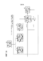
Фиг. 16 является блок-схемой подробной конфигурации модуля 102 интер-предсказания по фиг. 1.Fig. 16 is a block diagram of a detailed configuration of the
Фиг. 17 является блок-схемой подробной конфигурации модуля 301 извлечения режимов идентификации предикторов нормальных векторов движения по фиг. 16.Fig. 17 is a block diagram of a detailed configuration of the normal motion vector predictor identification
Фиг. 18 является блок-схемой подробной конфигурации модуля 302 извлечения режимов нормального объединения по фиг. 16.Fig. 18 is a block diagram of a detailed configuration of the normal combining
Фиг. 19 является пояснительной блок-схемой последовательности операций способа, показывающей процесс извлечения режимов идентификации предикторов нормальных векторов движения модуля 301 извлечения режимов идентификации предикторов нормальных векторов движения по фиг. 16.Fig. 19 is an explanatory flowchart showing a normal motion vector predictor identification mode extraction process of the normal motion vector predictor identification
Фиг. 20 является блок-схемой последовательности операций способа, показывающей процедуру обработки процесса извлечения режимов идентификации предикторов нормальных векторов движения.Fig. 20 is a flowchart showing a normal motion vector predictor identification mode extraction process processing procedure.
Фиг. 21 является пояснительной блок-схемой последовательности операций способа, показывающей процедуру обработки процесса извлечения режимов нормального объединения.Fig. 21 is an explanatory flowchart showing a normal combining mode extraction process processing procedure.
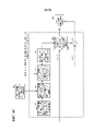
Фиг. 22 является блок-схемой подробной конфигурации модуля 203 интер-предсказания по фиг. 2.Fig. 22 is a block diagram of a detailed configuration of the
Фиг. 23 является блок-схемой подробной конфигурации модуля 401 извлечения режимов идентификации предикторов нормальных векторов движения по фиг. 22.Fig. 23 is a block diagram of a detailed configuration of the normal motion vector predictor identification
Фиг. 24 является блок-схемой подробной конфигурации модуля 402 извлечения режимов нормального объединения по фиг. 22.Fig. 24 is a block diagram of a detailed configuration of the normal combining
Фиг. 25 является пояснительной блок-схемой последовательности операций способа, показывающей процесс извлечения режимов идентификации предикторов нормальных векторов движения модуля 401 извлечения режимов идентификации предикторов нормальных векторов движения по фиг. 22.Fig. 25 is an explanatory flowchart showing a normal motion vector predictor identification mode extraction process of the normal motion vector predictor identification
Фиг. 26 является пояснительной схемой, показывающей процедуру обработки для инициализации/обновления списка потенциально подходящих вариантов предикторов векторов движения на основе предыстории.Fig. 26 is an explanatory diagram showing a processing procedure for initializing/updating a list of potentially candidate candidate motion vector predictors based on history.
Фиг. 27 является блок-схемой последовательности операций способа для процедуры обработки проверки на идентичные элементы в процедуре обработки для инициализации/обновления списка потенциально подходящих вариантов предикторов векторов движения на основе предыстории.Fig. 27 is a flowchart for the identity check processing procedure in the processing procedure for initializing/updating a list of potentially matching motion vector predictor cases based on history.
Фиг. 28 является блок-схемой последовательности операций способа для процедуры обработки поэлементного сдвига в процедуре обработки для инициализации/обновления списка потенциально подходящих вариантов предикторов векторов движения на основе предыстории.Fig. 28 is a flowchart for a pixel shift processing procedure in a processing procedure for initializing/updating a list of potentially suitable motion vector predictor cases based on history.
Фиг. 29 является пояснительной блок-схемой последовательности операций способа, показывающей процедуру обработки извлечения потенциально подходящих вариантов предикторов векторов движения на основе предыстории.Fig. 29 is an explanatory flowchart showing a history-based motion vector predictor candidate extraction processing procedure.
Фиг. 30 является пояснительной блок-схемой последовательности операций способа, показывающей процедуру обработки извлечения потенциально подходящих вариантов объединения на основе предыстории.Fig. 30 is an explanatory flowchart showing a processing procedure for extracting potentially suitable combinations based on history.
Фиг. 31A является пояснительной схемой, показывающей пример процесса обновления списков потенциально подходящих вариантов предикторов векторов движения на основе предыстории.Fig. 31A is an explanatory diagram showing an example of a process for updating lists of potentially candidate motion vector predictors based on history.
Фиг. 31B является пояснительной схемой, показывающей пример процесса обновления списков потенциально подходящих вариантов предикторов векторов движения на основе предыстории.Fig. 31B is an explanatory diagram showing an example of a process for updating lists of potentially candidate motion vector predictors based on history.
Фиг. 31C является пояснительной схемой, показывающей пример процесса обновления списков потенциально подходящих вариантов предикторов векторов движения на основе предыстории.Fig. 31C is an explanatory diagram showing an example of a process for updating lists of potentially candidate motion vector predictors based on history.
Фиг. 32 является пояснительной схемой, показывающей предсказание с компенсацией движения, когда время такта опорного кадра (RefL0Pic) L0 находится раньше времени такта целевого кадра (CurPic), в качестве L0-предсказания.Fig. 32 is an explanatory diagram showing motion compensation prediction when the cycle time of the reference frame (RefL0Pic) L0 is earlier than the cycle time of the target frame (CurPic) as the L0 prediction.
Фиг. 33 является пояснительной схемой, показывающей предсказание с компенсацией движения, когда время такта опорного кадра L0-предсказания находится позже времени такта целевого кадра, в качестве L0-предсказания.Fig. 33 is an explanatory diagram showing motion compensation prediction when the cycle time of the L0 prediction reference frame is later than the cycle time of the target frame as L0 prediction.
Фиг. 34 является пояснительной схемой, показывающей направление предсказания для предсказания с компенсацией движения, когда время такта опорного кадра L0-предсказания находится раньше времени такта целевого кадра, и время такта опорного кадра L1-предсказания находится позже времени такта целевого кадра, в качестве бипредсказания.Fig. 34 is an explanatory diagram showing a prediction direction for motion-compensated prediction when the clock time of the L0 prediction reference frame is earlier than the clock time of the target frame, and the clock time of the L1 prediction reference frame is later than the clock time of the target frame, as bi-prediction.
Фиг. 35 является пояснительной схемой, показывающей направление предсказания для предсказания с компенсацией движения, когда время такта опорного кадра L0-предсказания и время такта опорного кадра L1-предсказания находятся раньше времени такта целевого кадра, в качестве бипредсказания.Fig. 35 is an explanatory diagram showing a prediction direction for motion-compensated prediction when the cycle time of the L0 prediction reference frame and the cycle time of the L1 prediction reference frame are earlier than the cycle time of the target frame, as bi-prediction.
Фиг. 36 является пояснительной схемой, показывающей направление предсказания для предсказания с компенсацией движения, когда время такта опорного кадра L0-предсказания и время такта опорного кадра L1-предсказания находятся позже времени такта целевого кадра, в качестве бипредсказания.Fig. 36 is an explanatory diagram showing a prediction direction for motion-compensated prediction when the cycle time of the L0 prediction reference frame and the cycle time of the L1 prediction reference frame are later than the cycle time of the target frame, as bi-prediction.
Фиг. 37 является пояснительной схемой, показывающей пример аппаратной конфигурации устройства кодирования/декодирования согласно варианту осуществления настоящего изобретения.Fig. 37 is an explanatory diagram showing a hardware configuration example of an encoding/decoding apparatus according to an embodiment of the present invention.
Фиг. 38 является блок-схемой подробной конфигурации модуля 301 извлечения режимов идентификации предикторов нормальных векторов движения по фиг. 16 согласно второму варианту осуществления настоящего изобретения.Fig. 38 is a block diagram of a detailed configuration of the normal motion vector predictor identification
Фиг. 39 является блок-схемой подробной конфигурации модуля 401 извлечения режимов идентификации предикторов нормальных векторов движения по фиг. 22 согласно второму варианту осуществления настоящего изобретения.Fig. 39 is a block diagram of a detailed configuration of the normal motion vector predictor identification
Фиг. 40 является блок-схемой подробной конфигурации модуля 301 извлечения режимов идентификации предикторов нормальных векторов движения по фиг. 16 согласно третьему варианту осуществления настоящего изобретения.Fig. 40 is a block diagram of a detailed configuration of the normal motion vector predictor identification
Фиг. 41 является блок-схемой подробной конфигурации модуля 401 извлечения режимов идентификации предикторов нормальных векторов движения по фиг. 22 согласно третьему варианту осуществления настоящего изобретения.Fig. 41 is a block diagram of a detailed configuration of the normal motion vector predictor identification
Подробное описание вариантов осуществленияDetailed description of embodiments
[0011] В дальнейшем задаются технологические и технические термины, используемые в варианте осуществления.[0011] Hereinafter, the technological and technical terms used in the embodiment are specified.
[0012] Древовидный блок [0012] Tree block
В варианте осуществления, целевой кадр кодирования/декодирования одинаково разделяется на единицы предварительно определенного размера. Эта единица задается как древовидный блок. Хотя размер древовидного блока составляет 128×128 дискретных отсчетов на фиг. 4, размер древовидного блока не ограничен этим, и любой размер может задаваться. Древовидный блок цели (соответствующей цели кодирования в процессе кодирования или цели декодирования в процессе декодирования) переключается в порядке растрового сканирования, т.е. слева направо и сверху вниз. Внутренняя часть каждого древовидного блока дополнительно может рекурсивно разделяться. Блок, который представляет собой цель кодирования/декодирования после того, как древовидный блок рекурсивно разделяется, задается как блок кодирования. Кроме того, древовидный блок и блок кодирования совместно задаются в качестве блоков. Эффективное кодирование обеспечивается посредством выполнения соответствующего разбиения блоков. Размер древовидного блока может составлять фиксированное значение, предварительно определенное посредством устройства кодирования и устройства декодирования, или размер древовидного блока, определенный посредством устройства кодирования, может быть выполнен с возможностью передаваться в устройство декодирования. Здесь, максимальный размер древовидного блока составляет 128×128 дискретных отсчетов, и минимальный размер древовидного блока составляет 16×16 дискретных отсчетов. Кроме того, максимальный размер блока кодирования составляет 64×64 дискретных отсчета, и минимальный размер блока кодирования составляет 4×4 дискретных отсчета.In an embodiment, the encoding/decoding target frame is equally divided into units of a predetermined size. This unit is specified as a tree block. Although the treeblock size is 128×128 discrete samples in FIG. 4, the size of the tree block is not limited to this, and any size can be set. The tree block of the target (corresponding to the encoding target in the encoding process or the decoding target in the decoding process) is switched in the raster scan order, i.e. left to right and top to bottom. The interior of each treeblock may further be recursively split. The block that is the encoding/decoding target after the tree block is recursively divided is set as the encoding block. In addition, the tree block and the coding block are jointly defined as blocks. Efficient coding is ensured by performing appropriate block splitting. The treeblock size may be a fixed value predetermined by the encoder and the decoder, or the treeblock size determined by the encoder may be configured to be transmitted to the decoder. Here, the maximum treeblock size is 128×128 samples, and the minimum treeblock size is 16×16 samples. In addition, the maximum coding block size is 64×64 samples, and the minimum coding block size is 4×4 samples.
[0013] Режим предсказания [0013] Prediction mode
Переключение выполняется между интра-предсказанием (MODE_INTRA), в котором предсказание выполняется из обработанного сигнала кадров для целевого кадра, и интер-предсказанием (MODE_INTER), в котором предсказание выполняется из сигнала кадров для обработанного кадра в единицах целевых блоков кодирования.Switching is performed between intra-prediction (MODE_INTRA), in which prediction is performed from the processed frame signal for the target frame, and inter-prediction (MODE_INTER), in which prediction is performed from the frame signal for the processed frame in units of target coding units.
Обработанный кадр используется для кадра, сигнала кадров, древовидного блока, блока, блока кодирования и т.п., полученных посредством декодирования сигнала, полностью кодированного в процессе кодирования, и используется для кадра, сигнала кадров, древовидного блока, блока, блока кодирования и т.п., полученных посредством завершения декодирования в процессе декодирования.The processed frame is used for a frame, a frame signal, a treeblock, a block, an encoding block, or the like obtained by decoding a signal completely encoded in an encoding process, and is used for a frame, a frame signal, a treeblock, a block, an encoding block, etc. .p. obtained by completing decoding in the decoding process.
Режим, в котором идентифицируются интра-предсказание (MODE_INTRA) и интер-предсказание (MODE_INTER), задается как режим предсказания (PredMode). Режим предсказания (PredMode) имеет интра-предсказание (MODE_INTRA) или интер-предсказание (MODE_INTER) в качестве значения.The mode in which intra-prediction (MODE_INTRA) and inter-prediction (MODE_INTER) are identified is set as a prediction mode (PredMode). The prediction mode (PredMode) has intra-prediction (MODE_INTRA) or inter-prediction (MODE_INTER) as a value.
[0014] Интер-предсказание [0014] Inter prediction
При интер-предсказании, при котором предсказание выполняется из сигнала кадров для обработанного кадра, множество обработанных кадров могут использоваться в качестве опорных кадров. Чтобы управлять множеством опорных кадров, два типа опорных списков в виде L0 (опорного списка 0) и L1 (опорного списка 1) задаются, и опорный кадр идентифицируется с использованием каждого опорного индекса. В P-срезе, может использоваться L0-предсказание (Pred_L0). В B-срезе, могут использоваться L0-предсказание (Pred_L0), L1-предсказание (Pred_L1) и бипредсказание (Pred_BI). L0-предсказание (Pred_L0) представляет собой интер-предсказание, которое ссылается на опорный кадр, управляемый в L0, и L1-предсказание (Pred_L1) представляет собой интер-предсказание, которое ссылается на опорный кадр, управляемый в L1. Бипредсказание (Pred_BI) представляет собой интер-предсказание, при котором как выполняется L0-предсказание, так и L1-предсказание, и ссылаются на один опорный кадр, управляемый в каждом из L0 и L1. Информация для идентификации L0-предсказания, L1-предсказания и бипредсказания задается как режим интер-предсказания. В последующей обработке, константы и переменные с подстрочным индексом LX в выводе предположительно должны обрабатываться для каждого из L0 и L1.In inter-prediction, in which prediction is performed from a frame signal for a processed frame, a plurality of processed frames may be used as reference frames. In order to manage a plurality of reference frames, two types of reference lists in the form of L0 (reference list 0) and L1 (reference list 1) are defined, and the reference frame is identified using each reference index. In P-slice, L0 prediction (Pred_L0) can be used. In a B-slice, L0 prediction (Pred_L0), L1 prediction (Pred_L1), and biprediction (Pred_BI) can be used. L0 prediction (Pred_L0) is an inter prediction that refers to a reference frame driven in L0, and L1 prediction (Pred_L1) is an inter prediction that refers to a reference frame driven in L1. Bi-prediction (Pred_BI) is inter-prediction in which both L0 prediction and L1 prediction are performed, and refer to one reference frame driven in each of L0 and L1. Information for identifying L0 prediction, L1 prediction, and bi-prediction is set as an inter-prediction mode. In post-processing, constants and variables with subscript LX in the output are supposed to be processed for each of L0 and L1.
[0015] Режим идентификации предикторов векторов движения [0015] Motion vector predictor identification mode
Режим идентификации предикторов векторов движения представляет собой режим для передачи индекса для идентификации предиктора вектора движения, разности векторов движения, режима интер-предсказания и опорного индекса и определения информации интер-предсказания целевого блока. Предиктор вектора движения извлекается из потенциально подходящего варианта предиктора вектора движения, извлекаемого из обработанного блока, соседнего с целевым блоком, либо блока, расположенного в идентичной позиции или около (рядом) с целевым блоком из количества блоков, принадлежащих обработанному кадру, и индекса для идентификации предиктора вектора движения.The motion vector predictor identification mode is a mode for transmitting an index for identifying a motion vector predictor, a motion vector difference, an inter prediction mode, and a reference index, and determining target block inter prediction information. The motion vector predictor is derived from a potentially suitable motion vector predictor derived from a processed block adjacent to the target block, or a block located at or near the target block from the number of blocks belonging to the processed frame and an index to identify the predictor motion vector.
[0016] Режим объединения [0016] Combine Mode
Режим объединения представляет собой режим, в котором информация интер-предсказания целевого блока извлекается из информации интер-предсказания обработанного блока, соседнего с целевым блоком, либо блока, расположенного в идентичной позиции или около (рядом) с целевым блоком из количества блоков, принадлежащих обработанному кадру, без передачи разности векторов движения и опорного индекса.The merge mode is a mode in which the inter-prediction information of the target block is extracted from the inter-prediction information of the processed block adjacent to the target block, or the block located at the identical position or near (near) the target block from the number of blocks belonging to the processed frame , without transferring the difference of the motion vectors and the reference index.
[0017] Обработанный блок, соседний с целевым блоком, и информация интер-предсказания обработанного блока задаются как пространственные потенциально подходящие варианты объединения. Блок, расположенный в идентичной позиции или около (рядом) с целевым блоком из количества блоков, принадлежащих обработанному кадру, и информация интер-предсказания, извлекаемая из информации интер-предсказания блока, задаются как временные потенциально подходящие варианты объединения. Каждый потенциально подходящий вариант объединения регистрируется в списке потенциально подходящих вариантов объединения, и потенциально подходящий вариант объединения, используемый для предсказания целевого блока, идентифицируется посредством индекса объединения.[0017] The processed block adjacent to the target block and the inter-prediction information of the processed block are defined as spatial potential join candidates. A block located at or near the same position as the target block of the number of blocks belonging to the processed frame and the inter-prediction information extracted from the block's inter-prediction information are set as temporal potentially suitable joins. Each join candidate is registered in a join candidate list, and the join candidate used to predict the target block is identified by the join index.
[0018] Соседний блок [0018] Neighbor block
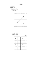
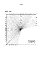
Фиг. 11 является пояснительной схемой, показывающей опорный блок, на который ссылаются при извлечении информации интер-предсказания в режиме идентификации предикторов векторов движения и режиме объединения. A0, A1, A2, B0, B1, B2 и B3 представляют собой обработанные блоки, соседние с целевым блоком. T0 представляет собой блок, расположенный в идентичной позиции или около (рядом) с целевым блоком в целевом кадре из количества блоков, принадлежащих обработанному кадру.Fig. 11 is an explanatory diagram showing a reference block referred to in extracting inter prediction information in the motion vector predictor identification mode and the combining mode. A0, A1, A2, B0, B1, B2 and B3 are processed blocks adjacent to the target block. T0 is a block located at or near the same position as the target block in the target frame out of the number of blocks belonging to the processed frame.
[0019] A1 и A2 представляют собой блоки, расположенные в левой стороне относительно целевого блока кодирования и соседние с целевым блоком кодирования. B1 и B3 представляют собой блоки, расположенные в верхней стороне относительно целевого блока кодирования и соседние с целевым блоком кодирования. A0, B0 и B2 представляют собой блоки, расположенные снизу слева, сверху справа и сверху слева относительно целевого блока кодирования, соответственно.[0019] A1 and A2 are blocks located on the left side of the coding target block and adjacent to the coding target block. B1 and B3 are blocks located on the upper side of the coding target block and adjacent to the coding target block. A0, B0, and B2 are bottom left, top right, and top left blocks of the target coding block, respectively.
[0020] Ниже описываются подробности того, как обрабатывать соседние блоки в режиме идентификации предикторов векторов движения и режиме объединения.[0020] The following describes the details of how to process adjacent blocks in the motion vector predictor identification mode and the merge mode.
[0021] Аффинная компенсация движения [0021] Affine Motion Compensation
Аффинная компенсация движения представляет собой процесс выполнения компенсации движения посредством разделения блока кодирования на субблоки предварительно определенной единицы и отдельного определения вектора движения для каждого из субблоков, на которые разделяется блок кодирования. Вектор движения каждого субблока извлекается на основе одной или более управляющих точек, извлекаемых из информации интер-предсказания обработанного блока, соседнего с целевым блоком, либо блока, расположенного в идентичной позиции или около (рядом) с целевым блоком из количества блоков, принадлежащих обработанному кадру. Хотя размер субблока составляет 4×4 дискретных отсчета в настоящем варианте осуществления, размер субблока не ограничен этим, и вектор движения может извлекаться в единицах дискретных отсчетов.Affine motion compensation is a process of performing motion compensation by dividing a coding block into subblocks of a predetermined unit and separately determining a motion vector for each of the subblocks into which the coding block is divided. The motion vector of each sub-block is extracted based on one or more control points extracted from the inter-prediction information of the processed block adjacent to the target block, or the block located at the identical position or near (near) the target block from the number of blocks belonging to the processed frame. Although the sub-block size is 4×4 discrete samples in the present embodiment, the sub-block size is not limited to this, and the motion vector can be extracted in units of discrete samples.
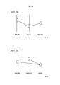
[0022] Пример аффинной компенсации движения в случае двух управляющих точек показывается на фиг. 14. В этом случае, две управляющих точки имеют два параметра в виде компонента горизонтального направления и компонента вертикального направления. Таким образом, аффинное преобразование в случае двух управляющих точек называется "четырехпараметрическим аффинным преобразованием". CP1 и CP2 по фиг. 14 представляют собой управляющие точки.[0022] An example of affine motion compensation in the case of two control points is shown in FIG. 14. In this case, the two control points have two parameters as a horizontal direction component and a vertical direction component. Thus, an affine transformation in the case of two control points is called a "four-parameter affine transformation". CP1 and CP2 in FIG. 14 are control points.
Пример аффинной компенсации движения в случае трех управляющих точек показывается на фиг. 15. В этом случае, три управляющих точки имеют два параметра в виде компонента горизонтального направления и компонента вертикального направления. Таким образом, аффинное преобразование в случае трех управляющих точек называется "шестипараметрическим аффинным преобразованием". CP1, CP2 и CP3 по фиг. 15 представляют собой управляющие точки.An example of affine motion compensation in the case of three control points is shown in FIG. 15. In this case, the three control points have two parameters as a horizontal direction component and a vertical direction component. Thus, the affine transformation in the case of three control points is called a "six-parameter affine transformation". CP1, CP2 and CP3 of FIG. 15 are control points.
[0023] Аффинная компенсация движения может использоваться как в режиме идентификации предикторов векторов движения, так и в режиме объединения. Режим, в котором аффинная компенсация движения применяется в режиме идентификации предикторов векторов движения, задается как режим идентификации предикторов векторов движения на основе субблоков, и режим, в котором аффинная компенсация движения применяется в режиме объединения, задается как режим объединения на основе субблоков.[0023] Affine motion compensation can be used in both motion vector predictor identification mode and pooling mode. The mode in which affine motion compensation is applied in the motion vector predictor identification mode is set as the sub-block-based motion vector predictor identification mode, and the mode in which affine motion compensation is applied in the combining mode is set as the sub-block-based combining mode.
[0024] Синтаксис интер-предсказания [0024] Inter prediction syntax
В дальнейшем описывается синтаксис, связанный со интер-предсказанием, с использованием фиг. 12 и 13.The following describes the syntax associated with inter-prediction using FIG. 12 and 13.
Флаг merge_flag на фиг. 12 указывает то, задается целевой блок кодирования в режим объединения или в режим идентификации предикторов векторов движения. Флаг merge_affine_flag указывает то, применяется или нет режим объединения на основе субблоков к целевому блоку кодирования режима объединения. Флаг inter_affine_flag указывает то, следует или нет применять режим идентификации предикторов векторов движения на основе субблоков к целевому блоку кодирования режима идентификации предикторов векторов движения. Флаг cu_affine_type_flag используется для того, чтобы определять количество управляющих точек в режиме идентификации предикторов векторов движения на основе субблоков.The merge_flag in FIG. 12 indicates whether the target coding block is set to the combining mode or the motion vector predictor identification mode. The merge_affine_flag flag indicates whether or not the subblock-based merging mode is applied to the target coding block of the merging mode. The inter_affine_flag indicates whether or not to apply the sub-block motion vector predictor identification mode to the target coding block of the motion vector predictor identification mode. The cu_affine_type_flag flag is used to determine the number of control points in the subblock-based motion vector predictor identification mode.
Фиг. 13 показывает значение каждого синтаксического элемента и способ предсказания, соответствующий ему. Режим нормального объединения соответствует merge_flag=1 и merge_affine_flag=0 и не представляет собой режим объединения на основе субблоков. Режим объединения на основе субблоков соответствует merge_flag=1 и merge_affine_flag=1. Режим идентификации предикторов нормальных векторов движения соответствует merge_flag=0 и inter_affine_flag=0. Режим идентификации предикторов нормальных векторов движения представляет собой режим объединения предиктора вектора движения, который не представляет собой режим идентификации предикторов векторов движения на основе субблоков. Режим идентификации предикторов векторов движения на основе субблоков соответствует merge_flag=0 и inter_affine_flag=1. Когда merge_flag=0 и inter_affine_flag=1, cu_affine_type_flag дополнительно передается, чтобы определять количество управляющих точек.Fig. 13 shows the meaning of each syntax element and the prediction method corresponding to it. The normal merging mode corresponds to merge_flag=1 and merge_affine_flag=0 and is not a sub-block based merging mode. The subblock-based merging mode corresponds to merge_flag=1 and merge_affine_flag=1. The normal motion vector predictor identification mode corresponds to merge_flag=0 and inter_affine_flag=0. The normal motion vector predictor identification mode is a motion vector predictor combining mode, which is not a subblock-based motion vector predictor identification mode. The subblock-based motion vector predictor identification mode corresponds to merge_flag=0 and inter_affine_flag=1. When merge_flag=0 and inter_affine_flag=1, cu_affine_type_flag is additionally passed to determine the number of control points.
[0025] POC [0025] POC
Номер в последовательности кадров (POC) представляет собой переменную, ассоциированную с кадром, который должен кодироваться, и задается равным значению, которое постепенно увеличивается на 1 согласно порядку вывода кадров. Согласно POC-значению, можно различать то, являются или нет кадры идентичными, чтобы различать переднезаднюю взаимосвязь между кадрами в порядке вывода или извлекать расстояние между кадрами. Например, если POC двух кадров имеют идентичное значение, может определяться то, что они представляют собой идентичный кадр. Когда POC двух кадров имеют различные значения, может определяться то, что кадр с меньшим POC-значением представляет собой кадр, который должен выводиться первым. Разность между POC двух кадров указывает межкадровое расстояние в направлении временной оси.A frame sequence number (POC) is a variable associated with a frame to be encoded and is set to a value that increments by 1 according to the frame output order. According to the POC value, it is possible to distinguish whether or not the frames are identical, to distinguish the anteroposterior relationship between frames in the output order, or to extract the distance between frames. For example, if the POCs of two frames have the same value, they may be determined to be the same frame. When the POCs of two frames have different values, it may be determined that the frame with the smaller POC value is the frame to be output first. The difference between the POC of two frames indicates the inter-frame distance in the direction of the time axis.
[0026] Первый вариант осуществления [0026] First Embodiment
В дальнейшем описываются устройство 100 кодирования кадров и устройство 200 декодирования кадров согласно первому варианту осуществления настоящего изобретения.In the following, the frame encoding apparatus 100 and the frame decoding apparatus 200 according to the first embodiment of the present invention will be described.
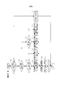
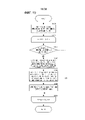
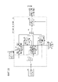
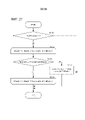
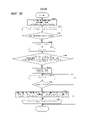
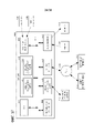
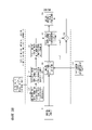
[0027] Фиг. 1 является блок-схемой устройства 100 кодирования кадров согласно первому варианту осуществления. Устройство 100 кодирования кадров согласно варианту осуществления включает в себя модуль 101 разбиения блоков, модуль 102 интер-предсказания, модуль 103 интра-предсказания, запоминающее устройство 104 декодированных кадров, модуль 105 определения способа предсказания, модуль 106 формирования остатков, модуль 107 ортогонального преобразования/квантования, модуль 108 кодирования битовых строк, модуль 109 обратного квантования/обратного ортогонального преобразования, модуль 110 наложения сигналов кадров для декодирования и запоминающее устройство 111 для хранения информации кодирования.[0027] FIG. 1 is a block diagram of a frame encoding apparatus 100 according to the first embodiment. The frame encoding apparatus 100 according to the embodiment includes a
[0028] Модуль 101 разбиения блоков рекурсивно разделяет входной кадр, чтобы формировать блок кодирования. Модуль 101 разбиения блоков включает в себя модуль квадратического разбиения, который разделяет разбитый целевой блок в горизонтальном направлении и в вертикальном направлении, и модуль двоичного/троичного разбиения, который разделяет разбитый целевой блок либо в горизонтальном направлении, либо в вертикальном направлении. Модуль 101 разбиения блоков задает сформированный блок кодирования в качестве целевого блока кодирования и предоставляет сигнал кадров целевого блока кодирования в модуль 102 интер-предсказания, модуль 103 интра-предсказания и модуль 106 формирования остатков. Кроме того, модуль 101 разбиения блоков предоставляет информацию, указывающую определенную структуру рекурсивного разбиения, в модуль 108 кодирования битовых строк. Ниже описывается подробная работа модуля 101 разбиения блоков.[0028] The
[0029] Модуль 102 интер-предсказания выполняет интер-предсказание целевого блока кодирования. Модуль 102 интер-предсказания извлекает множество потенциально подходящих вариантов информации интер-предсказания из информации интер-предсказания, сохраненной в запоминающем устройстве 111 для хранения информации кодирования, и декодированного сигнала кадров, сохраненного в запоминающем устройстве 104 декодированных кадров, выбирает подходящий режим интер-предсказания из множества извлеченных потенциально подходящих вариантов и предоставляет выбранный режим интер-предсказания и предсказанный сигнал кадров согласно выбранному режиму интер-предсказания в модуль 105 определения способа предсказания. Ниже описывается подробная конфигурация и работа модуля 102 интер-предсказания.[0029] The
[0030] Модуль 103 интра-предсказания выполняет интра-предсказание целевого блока кодирования. Модуль 103 интра-предсказания ссылается на декодированный сигнал кадров, сохраненный в запоминающем устройстве 104 декодированных кадров в качестве опорного дискретного отсчета, и формирует предсказанный сигнал кадров согласно интра-предсказанию на основе информации кодирования, такой как режим интра-предсказания, сохраненной в запоминающем устройстве 111 для хранения информации кодирования. При интра-предсказании, модуль 103 интра-предсказания выбирает подходящий режим интра-предсказания из множества режимов интра-предсказания и предоставляет выбранный режим интра-предсказания и предсказанный сигнал кадров согласно выбранному режиму интра-предсказания в модуль 105 определения способа предсказания.[0030] The
Примеры интра-предсказания показаны на фиг. 10A и 10B. Фиг. 10A показывает соответствие между направлением предсказания интра-предсказания и номером режима интра-предсказания. Например, в режиме 50 интра-предсказания, кадр интра-предсказания формируется посредством копирования опорных дискретных отсчетов в вертикальном направлении. Режим 1 интра-предсказания представляет собой DC-режим и представляет собой режим, в котором все выборочные значения целевого блока составляют среднее значение опорных дискретных отсчетов. Режим 0 интра-предсказания представляет собой планарный режим и представляет собой режим для создания двумерного кадра интра-предсказания из опорных дискретных отсчетов в вертикальном и горизонтальном направлениях. Фиг. 10B представляет собой пример, в котором кадр интра-предсказания, формируется в случае режима 40 интра-предсказания. Модуль 103 интра-предсказания копирует значение опорного дискретного отсчета в направлении, указываемом посредством режима интра-предсказания, относительно каждого дискретного отсчета целевого блока. Когда опорный дискретный отсчет режима интра-предсказания не находится в целочисленной позиции, модуль 103 интра-предсказания определяет опорное выборочное значение согласно интерполяции из опорных выборочных значений соседних целочисленных позиций.Examples of intra-prediction are shown in FIG. 10A and 10B. Fig. 10A shows the correspondence between the intra-prediction prediction direction and the intra-prediction mode number. For example, in
[0031] Запоминающее устройство 104 декодированных кадров сохраняет декодированный кадр, сформированный посредством модуля 110 наложения сигналов кадров для декодирования. Запоминающее устройство 104 декодированных кадров предоставляет сохраненный декодированный кадр в модуль 102 интер-предсказания и модуль 103 интра-предсказания.[0031] The decoded
[0032] Модуль 105 определения способа предсказания определяет оптимальный режим предсказания посредством оценки каждого интра-предсказания и интер-предсказания с использованием информации кодирования, остаточного объема кода, величины искажения между предсказанным сигналом кадров и целевым сигналом кадров и т.п. В случае интра-предсказания, модуль 105 определения способа предсказания предоставляет информацию интра-предсказания, такую как режим интра-предсказания, в качестве информации кодирования в модуль 108 кодирования битовых строк. В случае режима интер-предсказанного объединения, модуль 105 определения способа предсказания предоставляет информацию интер-предсказания, такую как индекс объединения и информация, указывающая то, представляет режим собой или нет режим объединения на основе субблоков (флаг объединения на основе субблоков), в качестве информации кодирования в модуль 108 кодирования битовых строк. В случае режима идентификации предикторов векторов движения интер-предсказания, модуль 105 определения способа предсказания предоставляет информацию интер-предсказания, такую как режим интер-предсказания, индекс предиктора вектора движения, опорные индексы L0 и L1, разность векторов движения и информация, указывающая то, представляет режим собой или нет режим идентификации предикторов векторов движения на основе субблоков (флаг предиктора вектора движения на основе субблоков), в качестве информации кодирования в модуль 108 кодирования битовых строк. Дополнительно, модуль 105 определения способа предсказания предоставляет определенную информацию кодирования в запоминающее устройство 111 для хранения информации кодирования. Модуль 105 определения способа предсказания предоставляет предсказанный сигнал кадров в модуль 106 формирования остатков и модуль 110 наложения сигналов кадров для декодирования.[0032] The prediction
[0033] Модуль 106 формирования остатков формирует остаток посредством вычитания предсказанного сигнала кадров из целевого сигнала кадров и предоставляет остаток в модуль 107 ортогонального преобразования/квантования.[0033] The
[0034] Модуль 107 ортогонального преобразования/квантования выполняет ортогональное преобразование и квантование для остатка в соответствии с параметром квантования, чтобы формировать ортогонально преобразованный/квантованный остаток, и предоставляет сформированный остаток в модуль 108 кодирования битовых строк и модуль 109 обратного квантования/обратного ортогонального преобразования.[0034] The orthogonal transform/
[0035] Модуль 108 кодирования битовых строк кодирует информацию кодирования согласно способу предсказания, определенному посредством модуля 105 определения способа предсказания для каждого блока кодирования, в дополнение к информации единиц последовательностей, кадров, срезов и блоков кодирования. В частности, модуль 108 кодирования битовых строк кодирует режим PredMode предсказания для каждого блока кодирования. Когда режим предсказания представляет собой интер-предсказание (MODE_INTER), модуль 108 кодирования битовых строк кодирует информацию кодирования (информацию интер-предсказания), такую как флаг для различения того, представляет или нет режим собой режим объединения, флаг объединения на основе субблоков, индекс объединения, когда режим представляет собой режим объединения, режим интер-предсказания, когда режим не представляет собой режим объединения, индекс предиктора вектора движения, информация относительно разности векторов движения и флаг предиктора вектора движения на основе субблоков в соответствии с указанным синтаксисом (синтаксическим правилом для битовых строк) и формирует первые битовые строки. Когда режим предсказания представляет собой интра-предсказание (MODE_INTRA), информация кодирования (информация интра-предсказания), такая как режим интра-предсказания кодируется в соответствии с указанным синтаксисом (синтаксическим правилом для битовых строк), и первые битовые строки формируются. Кроме того, модуль 108 кодирования битовых строк энтропийно кодирует ортогонально преобразованный и квантованный остаток в соответствии с указанным синтаксисом, чтобы формировать вторые битовые строки. Модуль 108 кодирования битовых строк мультиплексирует первые битовые строки и вторые битовые строки в соответствии с указанным синтаксисом и выводит поток битов.[0035] The bit
[0036] Модуль 109 обратного квантования/обратного ортогонального преобразования вычисляет остаток посредством выполнения обратного квантования и обратного ортогонального преобразования для ортогонально преобразованного/квантованного остатка, предоставляемого из модуля 107 ортогонального преобразования/квантования, и предоставляет вычисленный остаток в модуль 110 наложения сигналов кадров для декодирования.[0036] The inverse quantization/inverse
[0037] Модуль 110 наложения сигналов кадров для декодирования накладывает предсказанный сигнал кадров согласно определению модуля 105 определения способа предсказания и остаток, обратно квантованный и обратно ортогонально преобразованный посредством модуля 109 обратного квантования/обратного ортогонального преобразования, чтобы формировать декодированный кадр, и сохраняет декодированный кадр в запоминающем устройстве 104 декодированных кадров. Кроме того, модуль 110 наложения сигналов кадров для декодирования может сохранять декодированный кадр в запоминающем устройстве 104 декодированных кадров после выполнения процесса фильтрации для уменьшения искажения, такого как искажение в виде блочности вследствие кодирования для декодированного кадра.[0037] The frame
[0038] Запоминающее устройство 111 для хранения информации кодирования сохраняет информацию кодирования, такую как режим предсказания (интер-предсказание или интра-предсказание), определенный посредством модуля 105 определения способа предсказания. В случае интер-предсказания, информация кодирования, сохраненная в запоминающем устройстве 111 для хранения информации кодирования, включает в себя информацию интер-предсказания, такую как определенный вектор движения, опорные индексы опорных списков L0 и L1 и списка потенциально подходящих вариантов предикторов векторов движения на основе предыстории. Кроме того, в случае режима интер-предсказанного объединения, информация кодирования, сохраненная в запоминающем устройстве 111 для хранения информации кодирования, включает в себя информацию интер-предсказания, такую как индекс объединения и информация, указывающая то, представляет режим собой или нет режим объединения на основе субблоков (флаг объединения на основе субблоков), в дополнение к вышеописанной информации. Кроме того, в случае режима идентификации предикторов векторов движения интер-предсказания, информация кодирования, сохраненная в запоминающем устройстве 111 для хранения информации кодирования, включает в себя информацию интер-предсказания, такую как режим интер-предсказания, индекс предиктора вектора движения, разность векторов движения и информация, указывающая то, представляет режим собой или нет режим идентификации предикторов векторов движения на основе субблоков (флаг предиктора вектора движения на основе субблоков), в дополнение к вышеописанной информации. В случае интра-предсказания, информация кодирования, сохраненная в запоминающем устройстве 111 для хранения информации кодирования, включает в себя информацию интра-предсказания, такую как определенный режим интра-предсказания.[0038] The
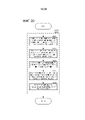
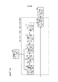
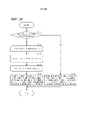
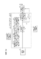
[0039] Фиг. 2 является блок-схемой, показывающей конфигурацию устройства декодирования кадров согласно варианту осуществления настоящего изобретения, соответствующего устройству кодирования кадров по фиг. 1. Устройство декодирования кадров согласно варианту осуществления включает в себя модуль 201 декодирования битовых строк, модуль 202 разбиения блоков, модуль 203 интер-предсказания, модуль 204 интра-предсказания, запоминающее устройство 205 для хранения информации кодирования, модуль 206 обратного квантования/обратного ортогонального преобразования, модуль 207 наложения сигналов кадров для декодирования и запоминающее устройство 208 декодированных кадров.[0039] FIG. 2 is a block diagram showing the configuration of a frame decoding apparatus according to an embodiment of the present invention corresponding to the frame encoding apparatus of FIG. 1. The frame decoding apparatus according to the embodiment includes a bit
[0040] Поскольку процесс декодирования устройства декодирования кадров по фиг. 2 соответствует процессу декодирования, предоставленному в устройстве кодирования кадров по фиг. 1, компоненты запоминающего устройства 205 для хранения информации кодирования, модуля 206 обратного квантования/обратного ортогонального преобразования, модуля 207 наложения сигналов кадров для декодирования и запоминающего устройства 208 декодированных кадров по фиг. 2 имеют функции, соответствующие компонентам запоминающего устройства 111 для хранения информации кодирования, модуля 109 обратного квантования/обратного ортогонального преобразования, модуля 110 наложения сигналов кадров для декодирования и запоминающего устройства 104 декодированных кадров устройства кодирования кадров по фиг. 1.[0040] Since the decoding process of the frame decoder of FIG. 2 corresponds to the decoding process provided in the frame encoder of FIG. 1, components of the
[0041] Поток битов, предоставляемый в модуль 201 декодирования битовых строк, разделяется в соответствии с указанным синтаксическим правилом. Модуль 201 декодирования битовых строк декодирует отделенную первую битовую строку и получает информацию единиц последовательностей, кадров, срезов, блоков кодирования и информацию кодирования единиц блоков кодирования. В частности, модуль 201 декодирования битовых строк декодирует режим PredMode предсказания для различения интер-предсказания (MODE_INTER) или интра-предсказания (MODE_INTRA) в единицах блоков кодирования. Когда режим предсказания представляет собой интер-предсказание (MODE_INTER), модуль 201 декодирования битовых строк декодирует информацию кодирования (информацию интер-предсказания) относительно флага для различения того, представляет или нет режим собой режим объединения, индекс объединения, когда режим представляет собой режим объединения, флаг объединения на основе субблоков, режим интер-предсказания, когда режим представляет собой режим идентификации предикторов векторов движения, индекс предиктора вектора движения, разность векторов движения, флаг предиктора вектора движения на основе субблоков и т.п. в соответствии с указанным синтаксисом и предоставляет информацию кодирования (информацию интер-предсказания) в запоминающее устройство 205 для хранения информации кодирования через модуль 203 интер-предсказания и модуль 202 разбиения блоков. Когда режим предсказания представляет собой интра-предсказание (MODE_INTRA), информация кодирования (информация интра-предсказания), такая как режим интра-предсказания декодируется в соответствии с указанным синтаксисом, и информация кодирования (информация интра-предсказания) предоставляется в запоминающее устройство 205 для хранения информации кодирования через модуль 203 интер-предсказания или модуль 204 интра-предсказания и модуль 202 разбиения блоков. Модуль 201 декодирования битовых строк декодирует отделенные вторые битовые строки, чтобы вычислять ортогонально преобразованный/квантованный остаток, и предоставляет ортогонально преобразованный/квантованный остаток в модуль 206 обратного квантования/обратного ортогонального преобразования.[0041] The bit stream provided to the bit
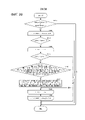
[0042] Когда режим PredMode предсказания целевого блока кодирования представляет собой режим идентификации предикторов векторов движения при интер-предсказании (MODE_INTER), модуль 203 интер-предсказания извлекает множество потенциально подходящих вариантов предикторов векторов движения с использованием информации кодирования ранее декодированного сигнала кадров, сохраненной в запоминающем устройстве 205 для хранения информации кодирования, и регистрирует множество извлеченных потенциально подходящих вариантов предикторов векторов движения в списке потенциально подходящих вариантов предикторов векторов движения, который описывается ниже. Модуль 203 интер-предсказания выбирает предиктор вектора движения согласно индексу предиктора вектора движения, декодированному и предоставляемому посредством модуля 201 декодирования битовых строк, из множества потенциально подходящих вариантов предикторов векторов движения, зарегистрированных в списке потенциально подходящих вариантов предикторов векторов движения, вычисляет вектор движения из разности векторов движения, декодированной посредством модуля 201 декодирования битовых строк, и выбранного предиктора вектора движения, и сохраняет вычисленный вектор движения в запоминающем устройстве 205 для хранения информации кодирования вместе с другой информацией кодирования. Информация кодирования блока кодирования, предоставляемая/сохраненная здесь, представляет собой режим PredMode предсказания, флаги predFlagL0[xP][yP] и predFlagL1[xP][yP], указывающие то, следует использовать L0-предсказание и L1-предсказание, опорные индексы refIdxL0[xP][yP] и refIdxL1[xP][yP] L0 и L1, векторы mvL0[xP][yP] и mvL1[xP][yP] движения L0 и L1 и т.п. Здесь, xP и yP представляют собой индексы, указывающие позицию верхнего левого дискретного отсчета блока кодирования в кадре. Когда режим PredMode предсказания представляет собой интер-предсказание (MODE_INTER), и режим интер-предсказания представляет собой L0-предсказание (Pred_L0), флаг predFlagL0, указывающий то, следует или нет использовать L0-предсказание, равен 1, и флаг predFlagL1, указывающий то, следует или нет использовать L1-предсказание, равен 0. Когда режим интер-предсказания представляет собой L1-предсказание (Pred_L1), флаг predFlagL0, указывающий то, следует или нет использовать L0-предсказание, равен, 0 и флаг predFlagL1, указывающий то, следует или нет использовать L1-предсказание, равен 1. Когда режим интер-предсказания представляет собой бипредсказание (Pred_BI), и флаг predFlagL0, указывающий то, следует или нет использовать L0-предсказание, и флаг predFlagL1, указывающий то, следует или нет использовать L1-предсказание, равны 1. Дополнительно, потенциально подходящие варианты объединения извлекаются в режиме объединения, в котором режим PredMode предсказания блока кодирования цели представляет собой интер-предсказание (MODE_INTER). Множество потенциально подходящих вариантов объединения извлекаются с использованием информации кодирования ранее декодированных блоков кодирования, сохраненной в запоминающем устройстве 205 для хранения информации кодирования, и регистрируются в списке потенциально подходящих вариантов объединения, который описывается ниже, потенциально подходящий вариант объединения, соответствующий индексу объединения, который должен декодироваться и предоставляться посредством модуля 201 декодирования битовых строк, выбирается из множества потенциально подходящих вариантов объединения, зарегистрированных в списке потенциально подходящих вариантов объединения, и информация интер-предсказания, такая как флаги predFlagL0[xP][yP] и predFlagL1[xP][yP], указывающие то, следует или нет использовать L0-предсказание и L1-предсказание выбранного потенциально подходящего варианта объединения, опорные индексы refIdxL0[xP][yP] и refIdxL1[xP][yP] L0 и L1 и векторы mvL0[xP][yP] и mvL1[xP][yP] движения L0 и L1, сохраняется в запоминающем устройстве 205 для хранения информации кодирования. Здесь, xP и yP представляют собой индексы, указывающие позицию верхнего левого дискретного отсчета блока кодирования в кадре. Ниже описывается подробная конфигурация и работа модуля 203 интер-предсказания.[0042] When the prediction mode PredMode of the target coding block is the inter-prediction motion vector predictor identification mode (MODE_INTER), the
[0043] Модуль 204 интра-предсказания выполняет интра-предсказание, когда режим PredMode предсказания блока кодирования цели представляет собой интра-предсказание (MODE_INTRA). Информация кодирования, декодированная посредством модуля 201 декодирования битовых строк, включает в себя режим интра-предсказания. Модуль 204 интра-предсказания формирует предсказанный сигнал кадров согласно интра-предсказанию из декодированного сигнала кадров, сохраненного в запоминающем устройстве 208 декодированных кадров, в соответствии с режимом интра-предсказания, включенным в информацию кодирования, декодированную посредством модуля 201 декодирования битовых строк, и предоставляет сформированный предсказанный сигнал кадров в модуль 207 наложения сигналов кадров для декодирования. Поскольку модуль 204 интра-предсказания соответствует модулю 103 интра-предсказания устройства 100 кодирования кадров, процесс, аналогичный процессу модуля 103 интра-предсказания, выполняется.[0043] The
[0044] Модуль 206 обратного квантования/обратного ортогонального преобразования выполняет обратное ортогональное преобразование и обратное квантование для ортогонально преобразованного/квантованного остатка, декодированного посредством модуля 201 декодирования битовых строк, и получает обратно ортогонально преобразованный/обратно квантованный остаток.[0044] The inverse quantization/inverse
[0045] Модуль 207 наложения сигналов кадров для декодирования декодирует сигнал кадров для декодирования посредством наложения предсказанного сигнала кадров, предсказанного в интер-режиме посредством модуля 203 интер-предсказания, или предсказанного сигнала кадров, предсказанного в интра-режиме посредством модуля 204 интра-предсказания, и остатка, обратно ортогонально преобразованного/обратно квантованного посредством модуля 206 обратного квантования/обратного ортогонального преобразования, и сохраняет декодированный сигнал кадров для декодирования в запоминающем устройстве 208 декодированных кадров. Во время хранения в запоминающем устройстве 208 декодированных кадров, модуль 207 наложения сигналов кадров для декодирования может сохранять декодированный кадр в запоминающем устройстве 208 декодированных кадров после того, как процесс фильтрации для уменьшения искажения в виде блочности и т.п. вследствие кодирования выполняется для декодированного кадра.[0045] The decoding frame
[0046] Далее описывается работа модуля 101 разбиения блоков в устройстве 100 кодирования кадров. Фиг. 3 является блок-схемой последовательности операций способа, показывающей операцию разделения кадра на древовидные блоки и дополнительного разделения каждого древовидного блока. Во-первых, входной кадр разделяется на древовидные блоки, имеющие предварительно определенный размер (этап S1001). Каждый древовидный блок сканируется в предварительно определенном порядке, т.е. в порядке растрового сканирования (этап S1002), и внутренняя часть древовидного блока цели разделяется (этап S1003).[0046] The operation of the
[0047] Фиг. 7 является блок-схемой последовательности операций способа, показывающей подробную работу процесса разбиения этапа S1003. Во-первых, определяется то, должен или нет целевой блок разделяться на четыре части (этап S1101).[0047] FIG. 7 is a flowchart showing the detailed operation of the partitioning process of step S1003. First, it is determined whether or not the target block is to be divided into four parts (step S1101).
[0048] Когда определяется то, что целевой блок должен разделяться на четыре части, целевой блок разделяется на четыре части (этап S1102). Каждый блок, полученный посредством разделения целевого блока, сканируется в порядке Z-сканирования, т.е. в порядке верхней левой, верхней правой, нижней левой и нижней правой частей (этап S1103). Фиг. 5 показывает пример порядка Z-сканирования, и ссылка с номером 601 по фиг. 6A показывает пример, в котором целевой блок разделяется на четыре части. Числа 0-3 ссылки с номером 601 по фиг. 6A указывают порядок обработки. Затем процесс разбиения по фиг. 7 рекурсивно выполняется для каждого блока из разделения на этапе S1101 (этап S1104).[0048] When it is determined that the target block is to be divided into four parts, the target block is divided into four parts (step S1102). Each block obtained by splitting the target block is scanned in Z-scan order, i.e. in the order of top left, top right, bottom left, and bottom right (step S1103). Fig. 5 shows an example of a Z-scan order, and
[0049] Когда определяется то, что целевой блок не должен разделяться на четыре части, двоичное/троичное разбиение выполняется (этап S1105).[0049] When it is determined that the target block is not to be quadrupled, binary/ternary splitting is performed (step S1105).
[0050] Фиг. 8 является блок-схемой последовательности операций способа, показывающей подробную работу процесса двоичного/троичного разбиения этапа S1105. Во-первых, определяется то, должен либо нет целевой блок разделяться на две или три части, т.е. то, должно либо нет выполняться двоичное или троичное разбиение (этап S1201).[0050] FIG. 8 is a flowchart showing the detailed operation of the binary/ternary partitioning process of step S1105. First, it is determined whether or not the target block should be divided into two or three parts, i.e. then whether or not binary or ternary partitioning is to be performed (step S1201).
[0051] Когда не определяется то, что целевой блок должен разделяться на две или три части, т.е. когда определяется то, что целевой блок не должен разделяться, разбиение завершается (этап S1211). Таким образом, процесс рекурсивного разбиения дополнительно не выполняется для блоков, разделенных согласно процессу рекурсивного разбиения.[0051] When it is not determined that the target block should be divided into two or three parts, i.e. when it is determined that the target block is not to be split, splitting is completed (step S1211). Thus, the recursive partitioning process is further not performed for the blocks divided according to the recursive partitioning process.
[0052] Когда определяется то, что целевой блок должен разделяться на две или три части, дополнительно определяется то, должен или нет целевой блок разделяться на две части (этап S1202).[0052] When it is determined that the target block is to be divided into two or three parts, it is further determined whether or not the target block is to be divided into two parts (step S1202).
[0053] Когда определяется то, что целевой блок должен разделяться на две части, определяется то, должен или нет целевой блок разделяться на верхнюю и нижнюю части (в вертикальном направлении) (этап S1203). На основе результата определения, целевой блок разделяется на две части, которые представляют собой верхнюю и нижнюю части (в вертикальном направлении) (этап S1204), или целевой блок разделяется на две части, которые представляют собой левую и правую части (в горизонтальном направлении) (этап S1205). Как результат этапа S1204, целевой блок разделяется на две части, которые представляют собой верхнюю и нижнюю части (в вертикальном направлении), как указано посредством ссылки с номером 602 на фиг. 6B. Как результат этапа S1205, целевой блок разделяется на две части, которые представляют собой левую и правую части (в горизонтальном направлении), как указано посредством ссылки с номером 604 по фиг. 6D.[0053] When it is determined that the target block is to be divided into two parts, it is determined whether or not the target block is to be divided into upper and lower parts (in the vertical direction) (step S1203). Based on the determination result, the target block is divided into two parts that are upper and lower parts (in the vertical direction) (step S1204), or the target block is divided into two parts that are left and right parts (in the horizontal direction) ( step S1205). As a result of step S1204, the target block is divided into two parts, which are upper and lower parts (in the vertical direction) as indicated by
[0054] Когда не определяется то, что целевой блок должен разделяться на две части, т.е. когда определяется то, что целевой блок должен разделяться на три части, на этапе S1202, определяется то, должен или нет целевой блок разделяться на верхнюю, среднюю и нижнюю части (в вертикальном направлении) (этап S1206). На основе результата определения, целевой блок разделяется на три части, которые представляют собой верхнюю, среднюю и нижнюю части (в вертикальном направлении) (этап S1207), или целевой блок разделяется на три части, которые представляют собой левую, среднюю и правую части (в горизонтальном направлении) (этап S1208). Как результат этапа S1207, целевой блок разделяется на три части, которые представляют собой верхнюю, среднюю и нижнюю части (в вертикальном направлении), как указано посредством ссылки с номером 603 по фиг. 6C. Как результат этапа S1208, целевой блок разделяется на три части, которые представляют собой левую, среднюю и правую части (в горизонтальном направлении), как указано посредством ссылки с номером 605 по фиг. 6E.[0054] When it is not determined that the target block should be divided into two parts, i.e. when it is determined that the target block is to be divided into three parts, at step S1202, it is determined whether or not the target block is to be divided into upper, middle and lower parts (in the vertical direction) (step S1206). Based on the determination result, the target block is divided into three parts that are the top, middle and bottom parts (in the vertical direction) (step S1207), or the target block is divided into three parts that are the left, middle and right parts (in horizontal direction) (step S1208). As a result of step S1207, the target block is divided into three parts, which are top, middle, and bottom (in the vertical direction) as indicated by
[0055] После того, как любой из этапов S1204, S1205, S1207 и S1208 выполняется, каждый из блоков, на которые разделяется целевой блок, сканируется в порядке слева направо и сверху вниз (этапе S1209). Номера 0-2 ссылок с номерами 602-605 по фиг. 6B в 6E указывают порядок обработки. Для каждого из блоков, на которые разделяется целевой блок, процесс двоичного/троичного разбиения по фиг. 8 рекурсивно выполняется (этап S1210).[0055] After any of steps S1204, S1205, S1207, and S1208 are executed, each of the blocks into which the target block is divided is scanned in order from left to right and top to bottom (step S1209). Reference numbers 0-2 602-605 of FIG. 6B to 6E indicate the processing order. For each of the blocks into which the target block is divided, the binary/ternary partitioning process of FIG. 8 is recursively executed (step S1210).
[0056] Рекурсивное разбиение блоков, описанное здесь, может ограничивать необходимость разбиения согласно количеству разбиений или размеру целевого блока и т.п. Информация, которая ограничивает необходимость разбиения, может реализовываться посредством конфигурации, в которой информация не доставляется посредством выполнения согласования между устройством кодирования и устройством декодирования заранее, либо реализовываться посредством конфигурации, в которой устройство кодирования определяет информацию, которая ограничивает необходимость разбиения, записывает информацию в битовую строку и доставляет информацию в устройство декодирования.[0056] The recursive block splitting described here may limit the need for splitting according to the number of splits or target block size, or the like. The information that limits the need for splitting may be realized by a configuration in which information is not delivered by performing negotiation between the encoding device and the decoding device in advance, or implemented by a configuration in which the encoding device determines information that limits the need for splitting, writes information to a bit string. and delivers the information to the decoding device.
[0057] Когда определенный блок разделяется, блок перед разбиением называется "родительским блоком", и каждый блок после разбиения называется "дочерним блоком".[0057] When a certain block is split, the block before splitting is called a "parent block", and each block after splitting is called a "child block".
[0058] Далее описывается работа модуля 202 разбиения блоков в устройстве 200 декодирования кадров. Модуль 202 разбиения блоков разделяет древовидный блок согласно процедуре обработки, аналогичной процедуре модуля 101 разбиения блоков устройства 100 кодирования кадров. Тем не менее, имеется отличие в том, что модуль 101 разбиения блоков устройства 100 кодирования кадров применяет технологию оптимизации, такую как оценка оптимальной формы на основе распознавания кадров либо оптимизация показателя искажения, чтобы определять оптимальную форму разбиения блоков, тогда как модуль 202 разбиения блоков устройства 200 декодирования кадров определяет форму разбиения блоков посредством информации разбиения декодирования блока, записанной в битовой строке.[0058] The following describes the operation of the
[0059] Синтаксис (синтаксическое правило для битовых строк), связанный с разбиением блоков согласно первому варианту осуществления, показывается на фиг. 9; coding_quadtree() представляет синтаксис, связанный с процессом квадратического разбиения для блока; multi_type_tree() представляет синтаксис, связанный с процессом двоичного или троичного разбиения для блока; qt_split представляет собой флаг, указывающий то, разделяется или нет блок на четыре части; qt_split=1, когда блок разделяется на четыре части, и qt_split=0, когда блок не разделяется на четыре части. Когда блок разделяется на четыре части (qt_split=1), процесс квадратического разбиения рекурсивно выполняется для блоков, каждый из которых разделен на четыре части (coding_quadtree (0), coding_quadtree (1), coding_quadtree (2), coding_quadtree (3), и аргументы 0-3 соответствуют числам, указываемым посредством ссылки с номером 601 по фиг. 6A). Когда блок не разделяется на четыре части (qt_split=0), последующее разбиение определяется согласно multi_type_tree(); mtt_split представляет собой флаг, указывающий то, выполняется дополнительно разбиение либо нет. Когда разбиение дополнительно выполняется (mtt_split=1), передаются mtt_split_vertical, который представляет собой флаг, указывающий то, разделяется блок вертикально или горизонтально, и mtt_split_binary, который представляет собой флаг для определения того, выполняется двоичное или троичное разбиение; mtt_split_vertical=1 указывает разбиение в вертикальном направлении, и mtt_split_vertical=0 указывает разбиение в горизонтальном направлении; mtt_split_binary=1 указывает двоичное разбиение, и mtt_split_binary=0 указывает троичное разбиение. При двоичном разбиении (mtt_split_binary=1), процесс разбиения рекурсивно выполняется для блоков, каждый из которых разделяется на две части (multi_type_tree (0), multi_type_tree (1), и аргументы 0-1 соответствуют числам, указываемым посредством ссылки с номером 602 или 604 на фиг. 6B в 6D). В случае троичного разбиения (mtt_split_binary=0), процесс разбиения рекурсивно выполняется для блоков, каждый из которых разделяется на три части (multi_type_tree (0), multi_type_tree (1), multi_type_tree (2), и аргументы 0-2 соответствуют числам, указываемым посредством ссылки с номером 603 по фиг. 6B, или числам, указываемым посредством ссылки с номером 605 по фиг. 6E). До тех пор, пока mtt_split=0 не достигается, иерархическое разбиение блоков выполняется посредством рекурсивного вызова multi_type_tree.[0059] The syntax (syntax rule for bit strings) associated with block splitting according to the first embodiment is shown in FIG. nine; coding_quadtree() represents the syntax associated with the quad splitting process for a block; multi_type_tree() represents the syntax associated with the binary or ternary splitting process for a block; qt_split is a flag indicating whether or not the block is split into four parts; qt_split=1 when the block is quadrupled, and qt_split=0 when the block is not quadrupled. When a block is split into four parts (qt_split=1), the quadratic splitting process is performed recursively on blocks each divided into four parts (coding_quadtree(0), coding_quadtree(1), coding_quadtree(2), coding_quadtree(3), and arguments 0-3 correspond to the numbers indicated by
[0060] Интер-предсказание [0060] Inter prediction
Способ интер-предсказания согласно варианту осуществления осуществляется в модуле 102 интер-предсказания устройства кодирования кадров по фиг. 1 и в модуле 203 интер-предсказания устройства декодирования кадров по фиг. 2.The inter-prediction method according to the embodiment is carried out in the
[0061] В дальнейшем описывается способ интер-предсказания согласно варианту осуществления со ссылкой на чертежи. Способ интер-предсказания осуществляется в процессах кодирования и декодирования в единицах блоков кодирования.[0061] Hereinafter, the inter-prediction method according to the embodiment will be described with reference to the drawings. The inter-prediction method is carried out in the coding and decoding processes in units of coding blocks.
[0062] Описание модуля 102 интер-предсказания на стороне кодирования [0062] Description of the
Фиг. 16 является схемой, показывающей подробную конфигурацию модуля 102 интер-предсказания устройства кодирования кадров на фиг. 1. Модуль 301 извлечения режимов идентификации предикторов нормальных векторов движения извлекает множество потенциально подходящих вариантов предикторов нормальных векторов движения, чтобы выбирать предиктор вектора движения, и вычисляет разность векторов движения между выбранным предиктором вектора движения и обнаруженным вектором движения. Обнаруженный режим интер-предсказания, опорный индекс и вектор движения и вычисленная разность векторов движения становятся информацией интер-предсказания режима идентификации предикторов нормальных векторов движения. Эта информация интер-предсказания предоставляется в модуль 305 определения режима интер-предсказания. Ниже описывается подробная конфигурация и процесс модуля 301 извлечения режимов идентификации предикторов нормальных векторов движения.Fig. 16 is a diagram showing a detailed configuration of the
[0063] Модуль 302 извлечения режимов нормального объединения извлекает множество потенциально подходящих вариантов нормального объединения, чтобы выбирать потенциально подходящий вариант нормального объединения, и получает информацию интер-предсказания режима нормального объединения. Эта информация интер-предсказания предоставляется в модуль 305 определения режима интер-предсказания. Ниже описывается подробная конфигурация и процесс модуля 302 извлечения режимов нормального объединения.[0063] The normal
[0064] Модуль 303 извлечения режимов идентификации предикторов векторов движения на основе субблоков извлекает множество потенциально подходящих вариантов предикторов векторов движения на основе субблоков, чтобы выбирать предиктор вектора движения на основе субблоков, и вычисляет разность векторов движения между выбранным предиктором вектора движения на основе субблоков и обнаруженным вектором движения. Обнаруженный режим интер-предсказания, опорный индекс и вектор движения и вычисленная разность векторов движения становятся информацией интер-предсказания режима идентификации предикторов векторов движения на основе субблоков. Эта информация интер-предсказания предоставляется в модуль 305 определения режима интер-предсказания.[0064] The sub-block-based motion vector predictor identification
[0065] Модуль 304 извлечения режимов объединения на основе субблоков извлекает множество потенциально подходящих вариантов объединения на основе субблоков, чтобы выбирать потенциально подходящий вариант объединения на основе субблоков, и получает информацию интер-предсказания режима объединения на основе субблоков. Эта информация интер-предсказания предоставляется в модуль 305 определения режима интер-предсказания.[0065] The subblock combining
[0066] Модуль 305 определения режима интер-предсказания определяет информацию интер-предсказания на основе информации интер-предсказания, предоставляемой из модуля 301 извлечения режимов идентификации предикторов нормальных векторов движения, модуля 302 извлечения режимов нормального объединения, модуля 303 извлечения режимов идентификации предикторов векторов движения на основе субблоков и модуля 304 извлечения режимов объединения на основе субблоков. Информация интер-предсказания согласно результату определения предоставляется из модуля 305 определения режима интер-предсказания в модуль 306 предсказания с компенсацией движения.[0066] The inter-prediction
[0067] Модуль 306 предсказания с компенсацией движения выполняет интер-предсказание для опорного сигнала кадров, сохраненного в запоминающем устройстве 104 декодированных кадров, на основе определенной информации интер-предсказания. Ниже описывается подробная конфигурация и процесс модуля 306 предсказания с компенсацией движения.[0067] The motion
[0068] Описание модуля 203 интер-предсказания декодирования на стороне декодирования [0068] Description of the decoding
Фиг. 22 является схемой, показывающей подробную конфигурацию модуля 203 интер-предсказания устройства декодирования кадров по фиг. 2.Fig. 22 is a diagram showing a detailed configuration of the
[0069] Модуль 401 извлечения режимов идентификации предикторов нормальных векторов движения извлекает множество потенциально подходящих вариантов предикторов нормальных векторов движения, чтобы выбирать предиктор вектора движения, вычисляет сумму выбранного предиктора вектора движения и декодированной разности векторов движения и задает вычисленную сумму в качестве вектора движения. Декодированный режим интер-предсказания, опорный индекс и вектор движения становятся информацией интер-предсказания режима идентификации предикторов нормальных векторов движения. Эта информация интер-предсказания предоставляется в модуль 406 предсказания с компенсацией движения через переключатель 408. Ниже описывается подробная конфигурация и процесс модуля 401 извлечения режимов идентификации предикторов нормальных векторов движения.[0069] The normal motion vector predictor
[0070] Модуль 402 извлечения режимов нормального объединения извлекает множество потенциально подходящих вариантов нормального объединения, чтобы выбирать потенциально подходящий вариант нормального объединения, и получает информацию интер-предсказания режима нормального объединения. Эта информация интер-предсказания предоставляется в модуль 406 предсказания с компенсацией движения через переключатель 408. Ниже описывается подробная конфигурация и процесс модуля 402 извлечения режимов нормального объединения.[0070] The normal
[0071] Модуль 403 извлечения режимов идентификации предикторов векторов движения на основе субблоков извлекает множество потенциально подходящих вариантов предикторов векторов движения на основе субблоков, чтобы выбирать предиктор вектора движения на основе субблоков, вычисляет сумму выбранного предиктора вектора движения на основе субблоков и декодированной разности векторов движения и задает вычисленную сумму в качестве вектора движения. Декодированный режим интер-предсказания, опорный индекс и вектор движения становятся информацией интер-предсказания режима идентификации предикторов векторов движения на основе субблоков. Эта информация интер-предсказания предоставляется в модуль 406 предсказания с компенсацией движения через переключатель 408.[0071] The sub-block-based motion vector predictor
[0072] Модуль 404 извлечения режимов объединения на основе субблоков извлекает множество потенциально подходящих вариантов объединения на основе субблоков, чтобы выбирать потенциально подходящий вариант объединения на основе субблоков, и получает информацию интер-предсказания режима объединения на основе субблоков. Эта информация интер-предсказания предоставляется в модуль 406 предсказания с компенсацией движения через переключатель 408.[0072] The sub-block combining
[0073] Модуль 406 предсказания с компенсацией движения выполняет интер-предсказание для опорного сигнала кадров, сохраненного в запоминающем устройстве 208 декодированных кадров, на основе определенной информации интер-предсказания. Подробная конфигурация и процесс модуля 406 предсказания с компенсацией движения являются аналогичными подробной конфигурации и процессу модуля 306 предсказания с компенсацией движения на стороне кодирования.[0073] The motion
[0074] Модуль извлечения режимов идентификации предикторов нормальных векторов движения (нормальное AMVP) [0074] Normal Motion Vector Predictor Identification Mode Extractor (Normal AMVP)
Модуль 301 извлечения режимов идентификации предикторов нормальных векторов движения по фиг. 17 включает в себя модуль 321 извлечения потенциально подходящих вариантов пространственных предикторов векторов движения, модуль 322 извлечения потенциально подходящих вариантов временных предикторов векторов движения, модуль 323 извлечения потенциально подходящих вариантов предикторов векторов движения на основе предыстории, модуль 325 пополнения потенциально подходящих вариантов предикторов векторов движения, модуль 326 обнаружения нормальных векторов движения, модуль 327 выбора потенциально подходящих вариантов предикторов векторов движения и модуль 328 вычитания векторов движения.The Normal Motion Vector Predictor
[0075] Модуль 401 извлечения режимов идентификации предикторов нормальных векторов движения по фиг. 23 включает в себя модуль 421 извлечения потенциально подходящих вариантов пространственных предикторов векторов движения, модуль 422 извлечения потенциально подходящих вариантов временных предикторов векторов движения, модуль 423 извлечения потенциально подходящих вариантов предикторов векторов движения на основе предыстории, модуль 425 пополнения потенциально подходящих вариантов предикторов векторов движения, модуль 426 выбора потенциально подходящих вариантов предикторов векторов движения и модуль 427 суммирования векторов движения.[0075] The Normal Motion Vector Predictor
[0076] В дальнейшем описываются процедуры обработки модуля 301 извлечения режимов идентификации предикторов нормальных векторов движения на стороне кодирования и модуля 401 извлечения режимов идентификации предикторов нормальных векторов движения на стороне декодирования с использованием блок-схем последовательности операций способа по фиг. 19 и 25, соответственно. Фиг. 19 является блок-схемой последовательности операций способа, показывающей процедуру обработки извлечения режимов идентификации предикторов нормальных векторов движения модуля 301 извлечения режимов идентификации предикторов нормальных векторов движения на стороне кодирования, и фиг. 25 является блок-схемой последовательности операций способа, показывающей процедуру обработки извлечения режимов идентификации предикторов нормальных векторов движения модуля 401 извлечения режимов идентификации предикторов нормальных векторов движения на стороне декодирования.[0076] In the following, the processing procedures of the normal motion vector predictor identification
[0077] Модуль извлечения режимов идентификации предикторов нормальных векторов движения (нормальное AMVP): описание на стороне кодирования [0077] Normal Motion Vector Predictor Identification Mode Extractor (Normal AMVP): Coding Side Description
В дальнейшем описывается процедура обработки извлечения режимов идентификации предикторов нормальных векторов движения на стороне кодирования со ссылкой на фиг. 19. В описании процедуры обработки по фиг. 19, термин "нормальный", показанный на фиг. 19, может опускаться.In the following, a normal motion vector predictor identification mode extraction processing procedure on the encoding side will be described with reference to FIG. 19. In the description of the processing procedure of FIG. 19, the term "normal" shown in FIG. 19 may be omitted.
[0078] Во-первых, модуль 326 обнаружения нормальных векторов движения обнаруживает нормальный вектор движения для каждого режима интер-предсказания и каждого опорного индекса (этап S100 по фиг. 19).[0078] First, the normal motion
[0079] Затем, в модуле 321 извлечения потенциально подходящих вариантов пространственных предикторов векторов движения, модуле 322 извлечения потенциально подходящих вариантов временных предикторов векторов движения, модуле 323 извлечения потенциально подходящих вариантов предикторов векторов движения на основе предыстории, модуле 325 пополнения потенциально подходящих вариантов предикторов векторов движения, модуле 327 выбора потенциально подходящих вариантов предикторов векторов движения и модуле 328 вычитания векторов движения, разность векторов движения для вектора движения, используемого для интер-предсказания режима идентификации предикторов нормальных векторов движения, вычисляется для каждого из L0 и L1 (этапы S101-S106 по фиг. 19). В частности, когда режим PredMode предсказания целевого блока представляет собой интер-предсказание (MODE_INTER), и режим интер-предсказания представляет собой L0-предсказание (Pred_L0), список mvpListL0 потенциально подходящих вариантов предикторов векторов движения L0 вычисляется, чтобы выбирать предиктор mvpL0 вектора движения, и разность mvdL0 векторов движения вектора mvL0 движения L0 вычисляется. Когда режим интер-предсказания целевого блока представляет собой L1-предсказание (Pred_L1), список mvpListL1 потенциально подходящих вариантов предикторов векторов движения L1 вычисляется, чтобы выбирать предиктор mvpL1 вектора движения, и разность mvdL1 векторов движения вектора mvL1 движения L1 вычисляется. Когда режим интер-предсказания целевого блока представляет собой бипредсказание (Pred_BI), L0-предсказание и L1-предсказание выполняются, список mvpListL0 потенциально подходящих вариантов предикторов векторов движения L0 вычисляется, чтобы выбирать предиктор mvpL0 вектора движения L0, разность mvdL0 векторов движения вектора mvL0 движения L0 вычисляется, список mvpListL1 потенциально подходящих вариантов предикторов векторов движения L1 вычисляется, чтобы выбирать предиктор mvpL1 вектора движения L1, и разность mvdL1 векторов движения вектора mvL1 движения L1 вычисляется.[0079] Then, in the spatial motion vector predictor
[0080] Хотя процесс вычисления разностей векторов движения выполняется для каждого из L0 и L1, процесс вычисления разностей векторов движения становится процессом, общим для L0 и L1. Следовательно, в нижеприведенном описании, L0 и L1 представляются как общий LX. X LX равен 0 в процессе вычисления разности векторов движения L0, и X LX равен 1 в процессе вычисления разности векторов движения L1. Кроме того, когда на информацию другого списка вместо LX ссылаются в ходе процесса вычисления разности векторов движения LX, другой список представляется как LY.[0080] Although the motion vector difference calculation process is performed for each of L0 and L1, the motion vector difference calculation process becomes a process common to L0 and L1. Therefore, in the description below, L0 and L1 are represented as common LX. X LX is equal to 0 in the process of calculating the motion vector difference L0, and X LX is equal to 1 in the process of calculating the motion vector difference L1. In addition, when other list information instead of LX is referenced during the LX motion vector difference calculation process, the other list is represented as LY.
[0081] Когда вектор mvLX движения LX используется (этап S102 по фиг. 19: "Да"), потенциально подходящие варианты предикторов векторов движения LX вычисляются, чтобы конструировать список mvpListLX потенциально подходящих вариантов предикторов векторов движения LX (этап S103 по фиг. 19). В модуле 321 извлечения потенциально подходящих вариантов пространственных предикторов векторов движения, модуле 322 извлечения потенциально подходящих вариантов временных предикторов векторов движения, модуле 323 извлечения потенциально подходящих вариантов предикторов векторов движения на основе предыстории и модуле 325 пополнения потенциально подходящих вариантов предикторов векторов движения модуля 301 извлечения режимов идентификации предикторов нормальных векторов движения, множество потенциально подходящих вариантов предикторов векторов движения извлекаются, чтобы конструировать список mvpListLX потенциально подходящих вариантов предикторов векторов движения. Ниже описывается подробная процедура обработки этапа S103 по фиг. 19 с использованием блок-схемы последовательности операций способа по фиг. 20.[0081] When the LX motion vector mvLX is used (step S102 of FIG. 19: "Yes"), potentially candidate LX motion vector predictor candidates are computed to construct a list mvpListLX of potentially candidate LX motion vector predictor candidates (step S103 of FIG. 19) . In the spatial motion vector predictor candidate
[0082] Затем, модуль 327 выбора потенциально подходящих вариантов предикторов векторов движения выбирает предиктор mvpLX вектора движения LX из списка mvpListLX потенциально подходящих вариантов предикторов векторов движения LX (этап S104 по фиг. 19). Здесь, один элемент (i-ый элемент при подсчете с 0-ого элемента) в списке mvpListLX потенциально подходящих вариантов предикторов векторов движения представляется как mvpListLX[i]. Каждая разность векторов движения, которая представляет собой разность между вектором mvLX движения и каждым потенциально подходящим вариантом mvpListLX[i] предиктора вектора движения, сохраненным в списке mvpListLX потенциально подходящих вариантов предикторов векторов движения, вычисляется. Объем кода, когда разности векторов движения кодируются, вычисляется для каждого элемента (потенциально подходящего варианта предиктора вектора движения) списка mvpListLX потенциально подходящих вариантов предикторов векторов движения. Затем потенциально подходящий вариант mvpListLX[i] предиктора вектора движения, который минимизирует объем кода для каждого потенциально подходящего варианта предиктора вектора движения из количества элементов, зарегистрированных в списке mvpListLX потенциально подходящих вариантов предикторов векторов движения, выбирается в качестве предиктора mvpLX вектора движения, и его индекс i получается. Когда предусмотрено множество потенциально подходящих вариантов предикторов векторов движения, имеющих наименьший объем сформированного кода в списке mvpListLX потенциально подходящих вариантов предикторов векторов движения, потенциально подходящий вариант mvpListLX[i] предиктора вектора движения, представленный посредством меньшего числа в индексе i в списке mvpListLX потенциально подходящих вариантов предикторов векторов движения, выбирается в качестве оптимального предиктора mvpLX вектора движения, и его индекс i получается.[0082] Next, the potentially candidate motion vector predictor
[0083] Затем, модуль 328 вычитания векторов движения вычитает выбранный предиктор mvpLX вектора движения LX из вектора mvLX движения LX и вычисляет разность mvdLX векторов движения LX в качестве mvdLX=mvLX-mvpLX (этап S105 по фиг. 19).[0083] Next, the
[0084] Модуль извлечения режимов идентификации предикторов нормальных векторов движения (нормальное AMVP): описание на стороне декодирования [0084] Normal Motion Vector Predictor Identification Mode Extractor (Normal AMVP): Decoding Side Description
Далее описывается процедура обработки режима идентификации предикторов нормальных векторов движения на стороне декодирования со ссылкой на фиг. 25. На стороне декодирования, в модуле 421 извлечения потенциально подходящих вариантов пространственных предикторов векторов движения, модуле 422 извлечения потенциально подходящих вариантов временных предикторов векторов движения, модуле 423 извлечения потенциально подходящих вариантов предикторов векторов движения на основе предыстории и модуле 425 пополнения потенциально подходящих вариантов предикторов векторов движения, вектор движения для использования при интер-предсказании режима идентификации предикторов нормальных векторов движения вычисляется для каждого из L0 и L1 (этапы S201-S206 по фиг. 25). В частности, когда режим PredMode предсказания целевого блока представляет собой интер-предсказание (MODE_INTER), и режим интер-предсказания целевого блока представляет собой L0-предсказание (Pred_L0), список mvpListL0 потенциально подходящих вариантов предикторов векторов движения L0 вычисляется, чтобы выбирать предиктор mvpL0 вектора движения, и вектор mvL0 движения L0 вычисляется. Когда режим интер-предсказания целевого блока представляет собой L1-предсказание (Pred_L1), список mvpListL1 потенциально подходящих вариантов предикторов векторов движения L1 вычисляется, чтобы выбирать предиктор mvpL1 вектора движения, и вектор mvL1 движения L1 вычисляется. Когда режим интер-предсказания целевого блока представляет собой бипредсказание (Pred_BI), L0-предсказание и L1-предсказание выполняются, список mvpListL0 потенциально подходящих вариантов предикторов векторов движения L0 вычисляется, чтобы выбирать предиктор mvpL0 вектора движения L0, вектор mvL0 движения L0 вычисляется, список mvpListL1 потенциально подходящих вариантов предикторов векторов движения L1 вычисляется, чтобы выбирать предиктор mvpL1 вектора движения L1, и каждый вектор mvL1 движения L1 вычисляется.Next, the normal motion vector predictor identification mode processing procedure on the decoding side will be described with reference to FIG. 25. On the decoding side, in the spatial motion vector predictor
[0085] Хотя процесс вычисления вектора движения выполняется для каждого из L0 и L1 на стороне декодирования, аналогично стороне кодирования, процесс вычисления вектора движения становится процессом, общим для L0 и L1. Следовательно, в нижеприведенном описании, L0 и L1 представляются как общий LX. LX представляет режим интер-предсказания для использования при интер-предсказании целевого блока кодирования. X равен 0 в процессе вычисления вектора движения L0, и X равен 1 в процессе вычисления вектора движения L1. Кроме того, когда на информацию другого опорного списка вместо опорного списка, идентичного опорному списку опорного списка, идентичного опорному списку LX цели вычисления, ссылаются в ходе процесса вычисления вектора движения LX, другой опорный список представляется как LY.[0085] Although the motion vector calculation process is performed for each of L0 and L1 on the decoding side, similarly to the encoding side, the motion vector calculation process becomes a process common to L0 and L1. Therefore, in the description below, L0 and L1 are represented as common LX. LX represents an inter-prediction mode for use in inter-prediction of a target coding block. X is 0 in the process of calculating the motion vector L0, and X is 1 in the process of calculating the motion vector L1. In addition, when other reference list information instead of a reference list identical to the reference list of the reference list identical to the reference list LX of the calculation target is referenced during the calculation process of the motion vector LX, the other reference list is represented as LY.
[0086] Когда вектор mvLX движения LX используется (этап S202 по фиг. 25: "Да"), потенциально подходящие варианты предикторов векторов движения LX вычисляются, чтобы конструировать список mvpListLX потенциально подходящих вариантов предикторов векторов движения LX (этап S203 по фиг. 25). В модуле 421 извлечения потенциально подходящих вариантов пространственных предикторов векторов движения, модуле 422 извлечения потенциально подходящих вариантов временных предикторов векторов движения, модуле 423 извлечения потенциально подходящих вариантов предикторов векторов движения на основе предыстории и модуле 425 пополнения потенциально подходящих вариантов предикторов векторов движения модуля 401 извлечения режимов идентификации предикторов нормальных векторов движения, множество потенциально подходящих вариантов предикторов векторов движения вычисляются, чтобы конструировать список mvpListLX потенциально подходящих вариантов предикторов векторов движения. Ниже описывается подробная процедура обработки этапа S203 по фиг. 25 с использованием блок-схемы последовательности операций способа по фиг. 20.[0086] When an LX motion vector mvLX is used (step S202 of FIG. 25: Yes), potentially candidate LX motion vector predictor candidates are computed to construct a list mvpListLX of potentially candidate LX motion vector predictor candidates (step S203 of FIG. 25) . In the spatial motion vector predictor
[0087] Затем, потенциально подходящий вариант mvpListLX[mvpIdxLX] предиктора вектора движения, соответствующий индексу mvpIdxLX предиктора вектора движения, декодированного и предоставляемого посредством модуля 201 декодирования битовых строк из списка mvpListLX потенциально подходящих вариантов предикторов векторов движения, извлекается в качестве выбранного предиктора mvpLX вектора движения в модуле 426 выбора потенциально подходящих вариантов предикторов векторов движения (этап S204 по фиг. 25).[0087] Then, the motion vector predictor candidate mvpListLX[mvpIdxLX] corresponding to the motion vector predictor index mvpIdxLX decoded and provided by the bit
[0088] Затем, модуль 427 суммирования векторов движения суммирует разность mvdLX векторов движения LX, которая декодируется и предоставляется посредством модуля 201 декодирования битовых строк, и предиктор mvpLX вектора движения LX и вычисляет вектор mvLX движения LX в качестве mvLX=mvpLX+mvdLX (этап S205 по фиг. 25).[0088] Next, the motion
[0089] Модуль извлечения режимов идентификации предикторов нормальных векторов движения (нормальное AMVP): способ предсказания векторов движения [0089] Normal Motion Vector Predictor Identification Mode Extractor (Normal AMVP): Motion Vector Prediction Method
Фиг. 20 является блок-схемой последовательности операций способа, показывающей процедуру обработки процесса извлечения режимов идентификации предикторов нормальных векторов движения, имеющего функцию, общую для модуля 301 извлечения режимов идентификации предикторов нормальных векторов движения устройства кодирования кадров и модуля 401 извлечения режимов идентификации предикторов нормальных векторов движения устройства декодирования кадров согласно варианту осуществления настоящего изобретения.Fig. 20 is a flowchart showing a processing procedure of the normal motion vector predictor identification mode extraction process having a function common to the normal motion vector predictor identification
[0090] Модуль 301 извлечения режимов идентификации предикторов нормальных векторов движения и модуль 401 извлечения режимов идентификации предикторов нормальных векторов движения включают в себя список mvpListLX потенциально подходящих вариантов предикторов векторов движения. Список mvpListLX потенциально подходящих вариантов предикторов векторов движения имеет списковую структуру и содержит область хранения, в которой индекс предиктора вектора движения, указывающий местоположение в списке потенциально подходящих вариантов предикторов векторов движения, и потенциально подходящий вариант предиктора вектора движения, соответствующий индексу, сохраняется в качестве элементов. Номер индекса предиктора вектора движения начинается с 0, и потенциально подходящие варианты предикторов векторов движения сохраняются в области хранения списка mvpListLX потенциально подходящих вариантов предикторов векторов движения. В настоящем варианте осуществления, предполагается, что, по меньшей мере, два потенциально подходящих вариантов предикторов векторов движения (информация интер-предсказания) могут регистрироваться в списке mvpListLX потенциально подходящих вариантов предикторов векторов движения. Кроме того, переменная numCurrMvpCand, указывающая количество потенциально подходящих вариантов предикторов векторов движения, зарегистрированных в списке mvpListLX потенциально подходящих вариантов предикторов векторов движения, задается равной 0.[0090] The normal motion vector predictor
[0091] Модули 321 и 421 извлечения потенциально подходящих вариантов пространственных предикторов векторов движения извлекают потенциально подходящие варианты предикторов векторов движения из соседних блоков с левой стороны. В этом процессе, предиктор mvLXA вектора движения извлекается со ссылкой на информацию интер-предсказания соседнего блока с левой стороны (A0 или A1 по фиг. 11), т.е. на флаг, указывающий то, может или нет потенциально подходящий вариант предиктора вектора движения использоваться, вектор движения, опорный индекс и т.п., и извлеченный mvLXA добавляется в список mvpListLX потенциально подходящих вариантов предикторов векторов движения (этап S301 по фиг. 20). Кроме того, X равен 0 во время L0-предсказания, и X равен 1 во время L1-предсказания (это справедливо далее). Затем, модули 321 и 421 извлечения потенциально подходящих вариантов пространственных предикторов векторов движения извлекают потенциально подходящий вариант предиктора вектора движения из соседнего блока с верхней стороны. В этом процессе, предиктор mvLXB вектора движения извлекается со ссылкой на информацию интер-предсказания соседнего блока с верхней стороны (B0, B1 или B2 по фиг. 11), т.е. на флаг, указывающий то, может или нет потенциально подходящий вариант предиктора вектора движения использоваться, вектор движения, опорный индекс и т.п., и mvLXB добавляется в список mvpListLX потенциально подходящих вариантов предикторов векторов движения, если извлеченный mvLXA не равен извлеченному mvLXB (этап S302 по фиг. 20). Обработка этапов S301 и S302 по фиг. 20 является общей за исключением того, что позиции соседних блоков, на которые ссылаются, и количество соседних блоков, на которые ссылаются, отличаются, и извлекаются флаг availableFlagLXN, указывающий то, может или нет потенциально подходящий вариант предиктора вектора движения блока кодирования использоваться, вектор mvLXN движения и опорный индекс refIdxN (N представляет A или B, и это справедливо далее).[0091] Potential candidate spatial motion vector predictor candidate extractors 321 and 421 extract potentially candidate motion vector predictor candidates from neighboring blocks on the left side. In this process, the motion vector predictor mvLXA is extracted with reference to the inter-prediction information of the adjacent block on the left side (A0 or A1 in FIG. 11), i.e. to a flag indicating whether or not a potentially suitable motion vector predictor candidate, motion vector, reference index, or the like can be used, and the extracted mvLXA is added to the list mvpListLX of potentially candidate motion vector predictor candidates (step S301 of FIG. 20). In addition, X is 0 during L0 prediction and X is 1 during L1 prediction (this is true below). Next, the candidate spatial motion vector predictor candidate extractors 321 and 421 extract the candidate motion vector predictor candidate from the upper side adjacent block. In this process, the motion vector predictor mvLXB is extracted with reference to the inter-prediction information of the neighboring block on the upper side (B0, B1 or B2 in FIG. 11), i.e. to a flag indicating whether or not a potential candidate motion vector predictor can be used, a motion vector, a reference index, etc., and mvLXB is added to the mvpListLX list of potentially candidate motion vector predictors if the extracted mvLXA is not equal to the extracted mvLXB (step S302 in Fig. 20). The processing of steps S301 and S302 in FIG. 20 is common except that the referenced neighboring block positions and the number of referenced neighboring blocks are different, and an availableFlagLXN flag is retrieved indicating whether or not a potentially suitable coding block motion vector predictor option can be used, vector mvLXN movement and reference index refIdxN (N represents A or B, and this is true below).
[0092] Затем, модули 323 и 423 извлечения потенциально подходящих вариантов предикторов векторов движения на основе предыстории добавляют потенциально подходящие варианты предикторов векторов движения на основе предыстории, зарегистрированные в списке HmvpCandList потенциально подходящих вариантов предикторов векторов движения на основе предыстории, в список mvpListLX потенциально подходящих вариантов предикторов векторов движения (этап S304 по фиг. 20). Ниже описываются подробности процедуры обработки регистрации этапа S304 с использованием блок-схемы последовательности операций способа по фиг. 29.[0092] Next, the history-based motion vector predictor
[0093] Затем, модули 322 и 422 извлечения потенциально подходящих вариантов временных предикторов векторов движения извлекают потенциально подходящие варианты предикторов векторов движения из блоков в кадре, время которого отличается от кадра текущего целевого кадра. В этом процессе, извлекаются флаг availableFlagLXCol, указывающий то, может или нет потенциально подходящий вариант предиктора вектора движения блока кодирования кадра другого момента времени использоваться, вектор mvLXCol движения, опорный индекс refIdxCol и опорный список listCol, и mvLXCol добавляется в список mvpListLX потенциально подходящих вариантов предикторов векторов движения (этап S304 по фиг. 20).[0093] Next, the potential candidate temporal motion vector predictor candidate extractors 322 and 422 extract the candidate motion vector predictor candidates from blocks in a frame whose time is different from that of the current target frame. In this process, the availableFlagLXCol flag indicating whether or not the motion vector predictor candidate of the frame encoding block of another time point can be used, the motion vector mvLXCol, the reference index refIdxCol and the reference list listCol are extracted, and mvLXCol is added to the mvpListLX list of potentially candidate predictors. motion vectors (step S304 of FIG. 20).
[0094] Кроме того, предполагается, что процессы модулей 322 и 422 извлечения потенциально подходящих вариантов временных предикторов векторов движения могут опускаться в единицах последовательностей (SPS), кадров (PPS) или срезов.[0094] In addition, it is contemplated that the processes of
[0095] Затем, модули 325 и 425 пополнения потенциально подходящих вариантов предикторов векторов движения добавляют потенциально подходящие варианты предикторов векторов движения, имеющие предварительно определенное значение, к примеру, (0, 0) до тех пор, пока список mvpListLX потенциально подходящих вариантов предикторов векторов движения не удовлетворяется (S305 по фиг. 20).[0095] Next, the candidate motion vector predictor
[0096] Модуль извлечения режимов нормального объединения (нормальное объединение) [0096] Normal Combination Mode Extractor (Normal Combination)
Модуль 302 извлечения режимов нормального объединения по фиг. 18 включает в себя модуль 341 извлечения пространственных потенциально подходящих вариантов объединения, модуль 342 извлечения временных потенциально подходящих вариантов объединения, модуль 344 извлечения средних потенциально подходящих вариантов объединения, модуль 345 извлечения потенциально подходящих вариантов объединения на основе предыстории, модуль 346 пополнения потенциально подходящих вариантов объединения и модуль 347 выбора потенциально подходящих вариантов объединения.The normal
[0097] Модуль 402 извлечения режимов нормального объединения по фиг. 24 включает в себя модуль 441 извлечения пространственных потенциально подходящих вариантов объединения, модуль 442 извлечения временных потенциально подходящих вариантов объединения, модуль 444 извлечения средних потенциально подходящих вариантов объединения, модуль 445 извлечения потенциально подходящих вариантов объединения на основе предыстории, модуль 446 пополнения потенциально подходящих вариантов объединения и модуль 447 выбора потенциально подходящих вариантов объединения.[0097] The normal
[0098] Фиг. 21 является пояснительной блок-схемой последовательности операций способа, показывающей процедуру процесса извлечения режимов нормального объединения, имеющего функцию, общую для модуля 302 извлечения режимов нормального объединения устройства кодирования кадров и модуля 402 извлечения режимов нормального объединения устройства декодирования кадров согласно варианту осуществления настоящего изобретения.[0098] FIG. 21 is an explanatory flowchart showing a procedure of a normal combining mode extraction process having a function common to a normal combining
[0099] Далее поэтапно описываются различные процессы. Хотя в дальнейшем описывается случай, в котором тип slice_type среза представляет собой B-срез, если не указано иное в нижеприведенном описании, настоящее изобретение также может применяться к случаю P-среза. Тем не менее, когда тип slice_type среза представляет собой P-срез, поскольку только L0-предсказание (Pred_L0) предоставляется в качестве режима интер-предсказания, и L1-предсказание (Pred_L1) и бипредсказание (Pred_BI) отсутствуют, процесс, связанный с L1, может опускаться.[0099] The following describes the various processes step by step. Although the following describes the case in which the slice_type of the slice is a B-slice, unless otherwise indicated in the description below, the present invention can also be applied to the case of a P-slice. However, when the slice_type of a slice is a P-slice, since only L0 prediction (Pred_L0) is provided as an inter-prediction mode, and L1 prediction (Pred_L1) and bi-prediction (Pred_BI) are not present, the process associated with L1 may go down.
[0100] Модуль 302 извлечения режимов нормального объединения и модуль 402 извлечения режимов нормального объединения имеют список mergeCandList потенциально подходящих вариантов объединения. Список mergeCandList потенциально подходящих вариантов объединения имеет списковую структуру и содержит индекс объединения, указывающий местоположение в списке потенциально подходящих вариантов объединения, и область хранения, в которой потенциально подходящие варианты объединения, соответствующие индексу, сохраняются в качестве элементов. Номер индекса объединения начинается с 0, и потенциально подходящие варианты объединения сохраняются в области хранения списка mergeCandList потенциально подходящих вариантов объединения. В последующем процессе, потенциально подходящий вариант объединения i индекса объединения, зарегистрированного в списке mergeCandList потенциально подходящих вариантов объединения, представляется посредством mergeCandList[i]. В настоящем варианте осуществления, предполагается, что, по меньшей мере, шесть потенциально подходящих вариантов объединения (информация интер-предсказания) могут регистрироваться в списке mergeCandList потенциально подходящих вариантов объединения. Дополнительно, переменная numCurrMergeCand, указывающая количество потенциально подходящих вариантов объединения, зарегистрированных в списке mergeCandList потенциально подходящих вариантов объединения, задается равной 0.[0100] The normal
[0101] Модуль 341 извлечения пространственных потенциально подходящих вариантов объединения и модуль 441 извлечения пространственных потенциально подходящих вариантов объединения извлекают пространственные потенциально подходящие варианты объединения из блоков (B1, A1, B0, A0 и B2 по фиг. 11), смежных с левой стороной и верхней стороной целевого блока в порядке B1, A1, B0, A0 и B2, из информации кодирования, сохраненной в запоминающем устройстве 111 для хранения информации кодирования устройства кодирования кадров или в запоминающем устройстве 205 для хранения информации кодирования устройства декодирования кадров, и регистрируют извлеченные пространственные потенциально подходящие варианты объединения в списке mergeCandList потенциально подходящих вариантов объединения (этап S401 по фиг. 21). Здесь, задается N, указывающее любой один из пространственных потенциально подходящих вариантов B1, A1, B0, A0 и B2 объединения и временного потенциально подходящего варианта Col объединения. Извлекаются флаг availableFlagN, указывающий то, может быть использована или нет информация интер-предсказания блока N в качестве пространственного потенциально подходящего варианта объединения, опорный индекс refIdxL0N L0 и опорный индекс refIdxL1N L1 пространственного потенциально подходящего варианта N объединения, флаг predFlagL0N L0-предсказания, указывающий то, выполняется или нет L0-предсказание, флаг predFlagL1N L1-предсказания, указывающий то, выполняется или нет L1-предсказание, вектор mvL0N движения L0 и вектор mvL1N движения L1. Тем не менее, поскольку потенциально подходящий вариант объединения извлекается без ссылки на информацию интер-предсказания блока, включенную в блок кодирования, который является целью в настоящем варианте осуществления, пространственный потенциально подходящий вариант объединения с использованием информации интер-предсказания блока, включенной в целевой блок кодирования, не извлекается.[0101] The spatial
[0102] Затем, модуль 342 извлечения временных потенциально подходящих вариантов объединения и модуль 442 извлечения временных потенциально подходящих вариантов объединения извлекают временные потенциально подходящие варианты объединения из кадров различных моментов времени и регистрируют извлеченные временные потенциально подходящие варианты объединения в списке mergeCandList потенциально подходящих вариантов объединения (этап S402 по фиг. 21). Извлекаются флаг availableFlagCol, указывающий то, может или нет временной потенциально подходящий вариант объединения использоваться, флаг predFlagL0Col L0-предсказания, указывающий то, выполняется или нет L0-предсказание временного потенциально подходящего варианта объединения, флаг predFlagL1Col L1-предсказания, указывающий то, выполняется или нет L1-предсказание, вектор mvL0Col движения L0 и вектор mvL1Col движения L1.[0102] Next, the temporal
[0103] Кроме того, предполагается, что процессы модуля 342 извлечения временных потенциально подходящих вариантов объединения и модуля 442 извлечения временных потенциально подходящих вариантов объединения могут опускаться в единицах последовательностей (SPS), кадров (PPS) или срезов.[0103] In addition, it is contemplated that the processes of temporal
[0104] Затем, модуль 345 извлечения потенциально подходящих вариантов объединения на основе предыстории и модуль 445 извлечения потенциально подходящих вариантов объединения на основе предыстории регистрируют потенциально подходящие варианты предикторов векторов движения на основе предыстории, зарегистрированные в списке HmvpCandList потенциально подходящих вариантов предикторов векторов движения на основе предыстории, в списке mergeCandList потенциально подходящих вариантов объединения (этап S403 по фиг. 21).[0104] Next, the history-based candidate
Кроме того, когда количество numCurrMergeCand потенциально подходящих вариантов объединения, зарегистрированных в списке mergeCandList потенциально подходящих вариантов объединения, меньше максимального количества MaxNumMergeCand потенциально подходящих вариантов объединения, максимальное количество MaxNumMergeCand потенциально подходящих вариантов объединения задается в качестве верхнего предела количества numCurrMergeCand потенциально подходящих вариантов объединения, зарегистрированного в списке mergeCandList потенциально подходящих вариантов объединения, и потенциально подходящие варианты объединения на основе предыстории извлекаются и регистрируются в списке mergeCandList потенциально подходящих вариантов объединения.In addition, when the number of numCurrMergeCand candidate merges registered in the list of merge candidates mergeCandList is less than the maximum number of candidate merges MaxNumMergeCand , the maximum number of candidate merges MaxNumMergeCand is set as the upper limit of the number of candidate merges numCurrMergeCand registered in mergeCandList of potentially suitable merges, and potentially suitable merges based on history are retrieved and registered in the mergeCandList of potentially suitable merges.
[0105] Затем, модуль 344 извлечения средних потенциально подходящих вариантов объединения и модуль 444 извлечения средних потенциально подходящих вариантов объединения извлекают средний потенциально подходящий вариант объединения из списка mergeCandList потенциально подходящих вариантов объединения и добавляют извлеченный средний потенциально подходящий вариант объединения в список mergeCandList потенциально подходящих вариантов объединения (этап S404 по фиг. 21).[0105] Next, the average
Кроме того, когда количество numCurrMergeCand потенциально подходящих вариантов объединения, зарегистрированных в списке mergeCandList потенциально подходящих вариантов объединения, меньше максимального количества MaxNumMergeCand потенциально подходящих вариантов объединения, максимальное количество MaxNumMergeCand потенциально подходящих вариантов объединения задается в качестве верхнего предела количества numCurrMergeCand потенциально подходящих вариантов объединения, зарегистрированного в списке mergeCandList потенциально подходящих вариантов объединения, и средние потенциально подходящие варианты объединения извлекаются и регистрируются в списке mergeCandList потенциально подходящих вариантов объединения.In addition, when the number of numCurrMergeCand candidate merges registered in the list of merge candidates mergeCandList is less than the maximum number of candidate merges MaxNumMergeCand , the maximum number of candidate merges MaxNumMergeCand is set as the upper limit of the number of candidate merges numCurrMergeCand registered in mergeCandList of merge candidates, and the average merge candidates are retrieved and registered in the mergeCandList of merge candidates.
Здесь, средний потенциально подходящий вариант объединения представляет собой новый потенциально подходящий вариант объединения, имеющий вектор движения, полученный посредством усреднения векторов движения первого потенциально подходящего варианта объединения и второго потенциально подходящего варианта объединения, зарегистрированных в списке mergeCandList потенциально подходящих вариантов объединения, для каждого из L0-предсказания и L1-предсказания.Here, the average candidate merge is a new candidate merge having a motion vector obtained by averaging the motion vectors of the first candidate merge and the second candidate merge registered in the list of candidate merges mergeCandList for each of L0- predictions and L1 predictions.
[0106] Затем, в модуле 346 пополнения потенциально подходящих вариантов объединения и модуле 446 пополнения потенциально подходящих вариантов объединения, когда количество numCurrMergeCand потенциально подходящих вариантов объединения, зарегистрированных в списке mergeCandList потенциально подходящих вариантов объединения, меньше максимального количества MaxNumMergeCand потенциально подходящих вариантов объединения, максимальное количество MaxNumMergeCand потенциально подходящих вариантов объединения задается в качестве верхнего предела количества numCurrMergeCand потенциально подходящих вариантов объединения, зарегистрированного в списке mergeCandList потенциально подходящих вариантов объединения, и дополнительный потенциально подходящий вариант объединения извлекается и регистрируется в списке mergeCandList потенциально подходящих вариантов объединения (этап S405 по фиг. 21). В P-срезе, потенциально подходящий вариант объединения, для которого вектор движения имеет значение в (0, 0), и режим предсказания представляет собой L0-предсказание (Pred_L0), добавляется с использованием максимального количества MaxNumMergeCand потенциально подходящих вариантов объединения в качестве верхнего предела. В B-срезе, потенциально подходящий вариант объединения, для которого вектор движения имеет значение в (0, 0), и режим предсказания представляет собой бипредсказание (Pred_BI), добавляется. Опорный индекс, когда потенциально подходящий вариант объединения добавляется, отличается от ранее добавленного опорного индекса.[0106] Then, in the candidate merge
[0107] Затем, модуль 347 выбора потенциально подходящих вариантов объединения и модуль 447 выбора потенциально подходящих вариантов объединения выбирают потенциально подходящие варианты объединения из потенциально подходящих вариантов объединения, зарегистрированных в списке mergeCandList потенциально подходящих вариантов объединения. Модуль 347 выбора потенциально подходящих вариантов объединения на стороне кодирования выбирает потенциально подходящий вариант объединения посредством вычисления объема кода и величины искажения и предоставляет индекс объединения, указывающий выбранный потенциально подходящий вариант объединения, и информацию интер-предсказания потенциально подходящего варианта объединения в модуль 306 предсказания с компенсацией движения через модуль 305 определения режима интер-предсказания. С другой стороны, модуль 447 выбора потенциально подходящих вариантов объединения на стороне декодирования выбирает потенциально подходящий вариант объединения на основе декодированного индекса объединения и предоставляет выбранный потенциально подходящий вариант объединения в модуль 406 предсказания с компенсацией движения.[0107] Next, the merge candidate selection module 347 and the merge
[0108] Обновление списка потенциально подходящих вариантов предикторов векторов движения на основе предыстории [0108] Updating the list of potentially suitable motion vector predictors based on history
Далее подробно описываются способ инициализации и способ обновления списка HmvpCandList потенциально подходящих вариантов предикторов векторов движения на основе предыстории, предоставленного в запоминающем устройстве 111 для хранения информации кодирования на стороне кодирования и в запоминающем устройстве 205 для хранения информации кодирования на стороне декодирования. Фиг. 26 является пояснительной блок-схемой последовательности операций способа, показывающей процедуру обработки для инициализации/обновления списка потенциально подходящих вариантов предикторов векторов движения на основе предыстории.The following describes in detail the initialization method and the method for updating the list HmvpCandList of potentially suitable motion vector predictor candidates based on the history provided in the
[0109] В настоящем варианте осуществления, предполагается, что список HmvpCandList потенциально подходящих вариантов предикторов векторов движения на основе предыстории обновляется в запоминающем устройстве 111 для хранения информации кодирования и в запоминающем устройстве 205 для хранения информации кодирования. Модуль обновления списков потенциально подходящих вариантов предикторов векторов движения на основе предыстории может устанавливаться в модуле 102 интер-предсказания и модуле 203 интер-предсказания, чтобы обновлять список HmvpCandList потенциально подходящих вариантов предикторов векторов движения на основе предыстории.[0109] In the present embodiment, it is assumed that the list HmvpCandList of potentially suitable motion vector predictors based on history is updated in the
[0110] Список HmvpCandList потенциально подходящих вариантов предикторов векторов движения на основе предыстории первоначально задается в начале среза, список HmvpCandList потенциально подходящих вариантов предикторов векторов движения на основе предыстории обновляется, когда режим идентификации предикторов нормальных векторов движения или режим нормального объединения выбран посредством модуля 105 определения способа предсказания на стороне кодирования, и список HmvpCandList потенциально подходящих вариантов предикторов векторов движения на основе предыстории обновляется, когда информация предсказания, декодированная посредством модуля 201 декодирования битовых строк, задается относительно режима идентификации предикторов нормальных векторов движения или режима нормального объединения на стороне декодирования.[0110] The history based motion vector predictor candidate list HmvpCandList is initially set at the beginning of the slice, the history based motion vector predictor candidate list HmvpCandList is updated when the normal motion vector predictor identification mode or the normal combining mode is selected by the
[0111] Информация интер-предсказания, используемая, когда интер-предсказание выполняется в режиме идентификации предикторов нормальных векторов движения или режиме нормального объединения, регистрируется в качестве потенциально подходящего варианта hMvpCand информации интер-предсказания в списке HmvpCandList потенциально подходящих вариантов предикторов векторов движения на основе предыстории. Потенциально подходящий вариант hMvpCand информации интер-предсказания включает в себя опорный индекс refIdxL0 L0, опорный индекс refIdxL1 L1, флаг predFlagL0 L0-предсказания, указывающий то, выполняется или нет L0-предсказание, флаг predFlagL1 L1-предсказания, указывающий то, выполняется или нет L1-предсказание, вектор mvL0 движения L0 и вектор mvL1 движения L1.[0111] The inter-prediction information used when inter-prediction is performed in the normal motion vector predictor identification mode or the normal pooling mode is registered as a potential candidate hMvpCand of the inter prediction information in the history-based list of potential motion vector predictor candidates HmvpCandList . Potentially suitable inter prediction information hMvpCand includes L0 reference index refIdxL0, L1 reference index refIdxL1, L0 prediction flag predFlagL0 indicating whether L0 prediction is performed or not, L1 prediction flag predFlagL1 indicating whether L1 is performed or not. -prediction, motion vector mvL0 L0 and motion vector mvL1 L1.
[0112] Когда имеется информация интер-предсказания, имеющая значение, идентичное значению потенциально подходящего варианта hMvpCand информации интер-предсказания, из количества элементов (т.е. информации интер-предсказания), зарегистрированных в списке HmvpCandList потенциально подходящих вариантов предикторов векторов движения на основе предыстории, предоставленном в запоминающем устройстве 111 для хранения информации кодирования на стороне кодирования и в запоминающем устройстве 205 для хранения информации кодирования на стороне декодирования, элемент удаляется из списка HmvpCandList потенциально подходящих вариантов предикторов векторов движения на основе предыстории. С другой стороны, когда отсутствует информация интер-предсказания, имеющая значение, идентичное значению потенциально подходящего варианта hMvpCand информации интер-предсказания, элемент в начале списка HmvpCandList потенциально подходящих вариантов предикторов векторов движения на основе предыстории удаляется, и потенциально подходящий вариант hMvpCand информации интер-предсказания добавляется в конец списка HmvpCandList потенциально подходящих вариантов предикторов векторов движения на основе предыстории.[0112] When there is inter prediction information having a value identical to the value of the inter prediction information potential candidate hMvpCand, out of the number of elements (i.e., inter prediction information) registered in the list HmvpCandList of potentially candidate motion vector predictor candidates based on provided in the
[0113] количество элементов списка HmvpCandList потенциально подходящих вариантов предикторов векторов движения на основе предыстории, предоставленного в запоминающем устройстве 111 для хранения информации кодирования на стороне кодирования и в запоминающем устройстве 205 для хранения информации кодирования на стороне декодирования согласно настоящему изобретению, предположительно составляет шесть.[0113] The number of elements of the list HmvpCandList of potentially suitable motion vector predictor options based on history provided in the encoding
[0114] Во-первых, список HmvpCandList потенциально подходящих вариантов предикторов векторов движения на основе предыстории инициализируется в единицах срезов (этап S2101 по фиг. 26). Все элементы списка HmvpCandList потенциально подходящих вариантов предикторов векторов движения на основе предыстории являются пустыми в начале среза, и значение числа NumHmvpCand потенциально подходящих вариантов предикторов векторов движения на основе предыстории (текущего количества потенциально подходящих вариантов), зарегистрированных в списке HmvpCandList потенциально подходящих вариантов предикторов векторов движения на основе предыстории, может задаваться равным 0.[0114] First, the list HmvpCandList of potentially suitable motion vector predictor options based on history is initialized in units of slices (step S2101 of FIG. 26). All elements of the HmvpCandList list of potential candidates for motion vector predictors based on history are empty at the beginning of the slice, and the value of the number NumHmvpCand of potential candidates for motion vector predictors based on the history (the current number of candidates for potential candidates) registered in the list HmvpCandList of potential candidates for motion vector predictors based on history, can be set to 0.
[0115] Кроме того, инициализация списка HmvpCandList потенциально подходящих вариантов предикторов векторов движения на основе предыстории выполняется в единицах срезов (первого блока кодирования среза), но может выполняться в единицах кадров, плиток или строк древовидного блока.[0115] In addition, the initialization of the list HmvpCandList of potentially suitable variants of motion vector predictors based on history is performed in units of slices (the first slice coding block), but may be performed in units of frames, tiles, or rows of a tree block.
[0116] Затем, следующий процесс обновления списка HmvpCandList потенциально подходящих вариантов предикторов векторов движения на основе предыстории итеративно выполняется для каждого блока кодирования в срезе (этапы S2102-S2111 по фиг. 26).[0116] Then, the following process of updating the list HmvpCandList of potentially suitable motion vector predictor options based on the history is iteratively performed for each coding block in the slice (steps S2102-S2111 of FIG. 26).
[0117] Во-первых, начальная настройка выполняется для каждого блока кодирования. Флаг identicalCandExist, указывающий то, имеется или нет идентичный потенциально подходящий вариант, задается равным значению "ложь", и индекс removeIdx цели удаления, указывающий потенциально подходящий вариант цели удаления, задается равным 0 (этап S2103 по фиг. 26).[0117] First, the initial setting is performed for each coding block. The identicalCandExist flag indicating whether or not there is an identical candidate is set to false, and the removal target index removeIdx indicating the potential candidate to be removed is set to 0 (step S2103 of FIG. 26).
[0118] Определяется то, имеется или нет потенциально подходящий вариант hMvpCand информации интер-предсказания цели регистрации (этап S2104 по фиг. 26). Когда модуль 105 определения способа предсказания на стороне кодирования определяет то, что режим представляет собой режим идентификации предикторов нормальных векторов движения или режим нормального объединения, либо когда модуль 201 декодирования битовых строк на стороне декодирования декодирует режим в качестве режима идентификации предикторов нормальных векторов движения или режима нормального объединения, его информация интер-предсказания задается в качестве потенциально подходящего варианта hMvpCand информации интер-предсказания цели регистрации. Когда модуль 105 определения способа предсказания на стороне кодирования определяет то, что режим представляет собой режим интра-предсказания, режим идентификации предикторов векторов движения на основе субблоков или режим объединения на основе субблоков, либо когда модуль 201 декодирования битовых строк на стороне декодирования декодирует режим в качестве режима интра-предсказания, режима идентификации предикторов векторов движения на основе субблоков или режима объединения на основе субблоков, процесс обновления списка HmvpCandList потенциально подходящих вариантов предикторов векторов движения на основе предыстории не выполняется, и потенциально подходящий вариант hMvpCand информации интер-предсказания цели регистрации не существует. Когда отсутствует потенциально подходящий вариант hMvpCand информации интер-предсказания цели регистрации, этапы S2105-S2106 пропускаются (этап S2104 по фиг. 26: "Нет"). Когда имеется потенциально подходящий вариант hMvpCand информации интер-предсказания цели регистрации, обработка с этапа S2105 выполняется (этап S2104 по фиг. 26: "Да").[0118] It is determined whether or not there is a potential candidate hMvpCand of registration target inter prediction information (step S2104 of FIG. 26). When the encoding side prediction
[0119] Затем, определяется то, имеется или нет элемент (информация интер-предсказания), имеющий значение, идентичное значению потенциально подходящего варианта hMvpCand информации интер-предсказания цели регистрации, т.е. идентичного элемента, из количества элементов списка HmvpCandList потенциально подходящих вариантов предикторов векторов движения на основе предыстории (этап S2105 по фиг. 26). Фиг. 27 является блок-схемой последовательности операций способа для процедуры обработки проверки на идентичные элементы. Когда значение числа NumHmvpCand потенциально подходящих вариантов предикторов векторов движения на основе предыстории равно 0 (этап S2121 по фиг. 27: "Нет"), список HmvpCandList потенциально подходящих вариантов предикторов векторов движения на основе предыстории является пустым, и отсутствует идентичный потенциально подходящий вариант, так что этапы S2122-S2125 по фиг. 27 пропускаются, и текущая процедура обработки проверки на идентичные элементы завершается. Когда значение числа NumHmvpCand потенциально подходящих вариантов предикторов векторов движения на основе предыстории превышает 0 ("Да" на этапе S2121 по фиг. 27), обработка этапа S2123 итеративно выполняется до тех пор, пока индекс hMvpIdx предиктора вектора движения на основе предыстории не изменяется с 0 до NumHmvpCand-1 (этапы S2122-S2125 по фиг. 27). Во-первых, сравнение выполняется относительно того, является или нет hMvpIdx-ый элемент HmvpCandList[hMvpIdx] при подсчете с 0-ого элемента списка потенциально подходящих вариантов предикторов векторов движения на основе предыстории идентичным потенциально подходящему варианту hMvpCand информации интер-предсказания (этап S2123 по фиг. 27). Когда они являются идентичными (этап S2123 по фиг. 27: "Да"), флаг identicalCandExist, указывающий то, имеется или нет идентичный потенциально подходящий вариант, задается равным значению "истина", и индекс removeIdx цели удаления, указывающий позицию элемента цели удаления, задается равным текущему значению индекса hMvpIdx предиктора вектора движения на основе предыстории, и текущий процесс проверки на идентичные элементы завершается. Когда они не являются идентичными (этап S2123 по фиг. 27: "Нет"), hMvpIdx постепенно увеличивается на 1. Если индекс hMvpIdx предиктора вектора движения на основе предыстории меньше или равен NumHmvpCand-1, обработка с этапа S2123 выполняется.[0119] Next, it is determined whether or not there is an element (inter prediction information) having a value identical to the value of a potentially suitable variant hMvpCand of the registration target inter prediction information, i.e. identical element, from the number of elements of the list HmvpCandList of potentially suitable variants of motion vector predictors based on the history (step S2105 of Fig. 26). Fig. 27 is a flowchart of a process for identical check processing. When the value of the number NumHmvpCand of the history-based motion vector predictor potential candidates NumHmvpCand is 0 (S2121 of FIG. 27: No), the history-based motion vector predictor candidate list HmvpCandList is empty, and there is no identical candidate, so that steps S2122-S2125 of FIG. 27 are skipped, and the current identity check processing routine is terminated. When the value of the number NumHmvpCand of potentially suitable history-based motion vector predictor cases exceeds 0 (Yes in step S2121 of FIG. 27), the processing of step S2123 is iteratively performed until the history-based motion vector predictor index hMvpIdx changes from 0 to NumHmvpCand-1 (steps S2122-S2125 of FIG. 27). First, a comparison is made as to whether or not the hMvpIdx th element of HmvpCandList[hMvpIdx] is, when counted from the 0 th element of the history-based motion vector predictor candidate candidate list, identical to the inter prediction information candidate candidate hMvpCand (step S2123 to Fig. 27). When they are identical (step S2123 of FIG. 27: Yes), the identicalCandExist flag indicating whether or not there is an identical candidate is set to true, and the removeIdx index of the removal target indicating the element position of the removal target, is set to the current value of the history-based motion vector predictor index hMvpIdx, and the current identical checking process is terminated. When they are not identical (step S2123 of FIG. 27: No), hMvpIdx is incrementally increased by 1. If the history-based motion vector predictor index hMvpIdx is less than or equal to NumHmvpCand-1, the processing from step S2123 is executed.
[0120] Со ссылкой на блок-схему последовательности операций способа по фиг. 26 снова, процесс сдвига и добавления элемента списка HmvpCandList потенциально подходящих вариантов предикторов векторов движения на основе предыстории выполняется (этап S2106 по фиг. 26). Фиг. 28 является блок-схемой последовательности операций способа для процедуры обработки сдвига/добавления элемента списка HmvpCandList потенциально подходящих вариантов предикторов векторов движения на основе предыстории этапа S2106 по фиг. 26. Во-первых, определяется то, следует добавлять новый элемент после удаления элемента, сохраненного в списке HmvpCandList потенциально подходящих вариантов предикторов векторов движения на основе предыстории, либо добавлять новый элемент без удаления элемента. В частности, сравнение выполняется относительно того, представляет собой "истина" или нет флаг identicalCandExist, указывающий то, существует или нет идентичный потенциально подходящий вариант, либо того, равно NumHmvpCand или нет шести (этап S2141 по фиг. 28). Когда либо такое условие, что флаг identicalCandExist, указывающий то, имеется или нет идентичный потенциально подходящий вариант, представляет собой "истина", либо такое условие, что текущее количество NumHmvpCand потенциально подходящих вариантов равно шести, удовлетворяется (этап S2141 по фиг. 28: "Да"), новый элемент добавляется после удаления элемента, сохраненного в списке HmvpCandList потенциально подходящих вариантов предикторов векторов движения на основе предыстории. Начальное значение индекса i задается равным значению removeIdx+1. Процесс поэлементного сдвига этапа S2143 итеративно выполняется от этого начального значения до NumHmvpCand (этапы S2142-S2144 по фиг. 28). Посредством копирования элемента HmvpCandList[i] в HmvpCandList[i-1], элемент сдвигается вперед (этап S2143 по фиг. 28), и i постепенно увеличивается на 1 (этапы S2142-S2144 по фиг. 28). Затем, потенциально подходящий вариант hMvpCand информации интер-предсказания добавляется в (NumHmvpCand-1)-ый элемент HmvpCandList[NumHmvpCand-1] при подсчете с 0-ого элемента, который соответствует концу списка потенциально подходящих вариантов предикторов векторов движения на основе предыстории (этап S2145 по фиг. 28), и текущий процесс сдвига/добавления элемента списка HmvpCandList потенциально подходящих вариантов предикторов векторов движения на основе предыстории завершается. С другой стороны, когда ни такое условие, что флаг identicalCandExist, указывающий то, имеется или нет идентичный потенциально подходящий вариант, представляет собой "истина", ни такое условие что, текущее количество NumHmvpCand потенциально подходящих вариантов равно шести, не удовлетворяется (этап S2141 по фиг. 28: "Нет"), потенциально подходящий вариант hMvpCand информации интер-предсказания добавляется в конец списка потенциально подходящих вариантов предикторов векторов движения на основе предыстории без удаления элемента, сохраненного в списке HmvpCandList потенциально подходящих вариантов предикторов векторов движения на основе предыстории (этап S2146 по фиг. 28). Здесь, конец списка потенциально подходящих вариантов предикторов векторов движения на основе предыстории представляет собой NumHmvpCand-ый элемент HmvpCandList[numHmvpCand] при подсчете с 0-ого элемента. Кроме того, NumHmvpCand постепенно увеличивается на 1, и текущий процесс сдвига/добавления элемента списка HmvpCandList потенциально подходящих вариантов предикторов векторов движения на основе предыстории завершается.[0120] With reference to the flowchart of the method of FIG. 26 again, the process of shifting and adding a list item HmvpCandList of potentially suitable motion vector predictors based on history is performed (step S2106 of FIG. 26). Fig. 28 is a flowchart for the shift/add item HmvpCandList processing procedure of potentially suitable motion vector predictor options based on the history of step S2106 of FIG. 26. First, it is determined whether to add a new element after deleting an element stored in the HmvpCandList list of potentially suitable motion vector predictors based on history, or to add a new element without deleting the element. Specifically, a comparison is made as to whether or not the identicalCandExist flag indicating whether or not an identical candidate exists or whether or not NumHmvpCand is equal to or not six is "true" (step S2141 of FIG. 28). When either the condition that the identicalCandExist flag indicating whether or not there is an identical candidate is "true" or the condition that the current number of potential candidates NumHmvpCand is six is satisfied (step S2141 of FIG. 28: " Yes"), a new element is added after deleting an element stored in the HmvpCandList list of potentially eligible motion vector predictors based on history. The initial value of index i is set to the
[0121] Фиг. 31 является пояснительной схемой, показывающей пример процесса обновления списка потенциально подходящих вариантов предикторов векторов движения на основе предыстории. Когда новый элемент добавляется в список HmvpCandList потенциально подходящих вариантов предикторов векторов движения на основе предыстории, в котором зарегистрированы шесть элементов (информация интер-предсказания), элементы сравниваются с новой информацией интер-предсказания в порядке от переднего элемента списка HmvpCandList потенциально подходящих вариантов предикторов векторов движения на основе предыстории (фиг. 31A). Если новый элемент имеет значение, идентичное значению третьего элемента HMVP2 с начала списка HmvpCandList потенциально подходящих вариантов предикторов векторов движения на основе предыстории, элемент HMVP2 удаляется из списка HmvpCandList потенциально подходящих вариантов предикторов векторов движения на основе предыстории, и последующие элементы HMVP3-HMVP5 сдвигаются вперед (копируются) по одному, и новый элемент добавляется в конец списка HmvpCandList потенциально подходящих вариантов предикторов векторов движения на основе предыстории (фиг. 31B), чтобы завершать обновление списка HmvpCandList потенциально подходящих вариантов предикторов векторов движения на основе предыстории (фиг. 31C).[0121] FIG. 31 is an explanatory diagram showing an example of a process for updating a list of potentially candidate motion vector predictors based on history. When a new element is added to the history-based motion vector predictor potential candidate list HmvpCandList in which six elements (inter-prediction information) are registered, the elements are compared with the new inter-prediction information in order from the leading element of the motion vector predictor candidate list HmvpCandList based on history (FIG. 31A). If the new element has a value identical to the value of the third element of HMVP2 from the beginning of the HMVPCandList list of potentially candidate history-based motion vector predictors, the HMVP2 element is removed from the HMVPCandList of potentially candidate history-based motion vector predictor candidates, and subsequent HMVP3-HMVP5 elements are shifted forward ( are copied) one at a time, and a new element is added to the end of the HmvpCandList list of potentially suitable history-based motion vector predictor candidates (FIG. 31B) to complete the update of the HmvpCandList list of potentially candidate history-based motion vector predictor candidates (FIG. 31C).
[0122] Процесс извлечения потенциально подходящих вариантов предикторов векторов движения на основе предыстории [0122] The process of extracting potentially suitable variants of motion vector predictors based on the history
Далее подробно описывается способ извлечения потенциально подходящего варианта предиктора вектора движения на основе предыстории из списка HmvpCandList потенциально подходящих вариантов предикторов векторов движения на основе предыстории, который представляет собой процедуру обработки этапа S304 по фиг. 20, которая представляет собой процесс, общий для модуля 323 извлечения потенциально подходящих вариантов предикторов векторов движения на основе предыстории модуля 301 извлечения режимов идентификации предикторов нормальных векторов движения на стороне кодирования и модуля 423 извлечения потенциально подходящих вариантов предикторов векторов движения на основе предыстории модуля 401 извлечения режимов идентификации предикторов нормальных векторов движения на стороне декодирования. Фиг. 29 является пояснительной блок-схемой последовательности операций способа, показывающей процедуру обработки извлечения потенциально подходящих вариантов предикторов векторов движения на основе предыстории.The following describes in detail a method for extracting a potentially suitable history-based motion vector predictor candidate from a history-based motion vector predictor potential candidate list HmvpCandList, which is the processing procedure of step S304 of FIG. 20, which is a process common to the
[0123] Когда текущее количество numCurrMvpCand потенциально подходящих вариантов предикторов векторов движения превышает или равно максимальному количеству элементов в списке mvpListLX потенциально подходящих вариантов предикторов векторов движения (здесь, 2), или значение количества NumHmvpCand потенциально подходящих вариантов предикторов векторов движения на основе предыстории равно 0 ("Нет" на этапе S2201 по фиг. 29), обработка этапов S2202-S2209 по фиг. 29 опускается, и процедура обработки извлечения потенциально подходящих вариантов предикторов векторов движения на основе предыстории завершается. Когда текущее количество numCurrMvpCand потенциально подходящих вариантов предикторов векторов движения меньше 2, что представляет собой максимальное количество элементов списка mvpListLX потенциально подходящих вариантов предикторов векторов движения, и значение количества NumHmvpCand потенциально подходящих вариантов предикторов векторов движения на основе предыстории превышает 0 ("Да" на этапе S2201 по фиг. 29), обработка этапов S2202-S2209 по фиг. 29 выполняется.[0123] When the current number numCurrMvpCand of potential candidate motion vector predictor candidates is greater than or equal to the maximum number of elements in the list mvpListLX of candidate motion vector predictor candidates (here, 2), or the value of the number NumHmvpCand of potential candidate motion vector predictor candidates based on history is 0 ( No at step S2201 of Fig. 29), the processing of steps S2202 to S2209 of Fig. 29 is omitted, and the history-based motion vector predictor candidate extraction process is terminated. When the current number of candidate motion vector predictor candidates numCurrMvpCand is less than 2, which is the maximum number of elements of the candidate motion vector predictor candidate list mvpListLX, and the value of the number NumHmvpCand of candidate motion vector predictor candidates based on history is greater than 0 ("Yes" in step S2201 in Fig. 29), the processing of steps S2202-S2209 in Fig. 29 is being implemented.
[0124] Затем, обработка этапов S2203-S2208 по фиг. 29 итеративно выполняется до тех пор, пока индекс i не изменяется с 1 до меньшего значения из 4 и количества numCheckedHMVPCand потенциально подходящих вариантов предикторов векторов движения на основе предыстории (этапы S2202-S2209 по фиг. 29). Когда текущее количество numCurrMvpCand потенциально подходящих вариантов предикторов векторов движения превышает или равно 2, что представляет собой максимальное количество элементов списка mvpListLX потенциально подходящих вариантов предикторов векторов движения (этап S2203 по фиг. 29: "Нет"), обработка этапов S2204-S2209 на фиг. 29 опускается, и текущая процедура обработки извлечения потенциально подходящих вариантов предикторов векторов движения на основе предыстории завершается. Когда текущее количество numCurrMvpCand потенциально подходящих вариантов предикторов векторов движения меньше 2, что представляет собой максимальное количество элементов списка mvpListLX потенциально подходящих вариантов предикторов векторов движения (этап S2203 по фиг. 29: "Да"), обработка с этапа S2204 по фиг. 29 выполняется.[0124] Next, the processing of steps S2203-S2208 in FIG. 29 is iteratively executed until index i changes from 1 to the lower of 4 and the number numCheckedHMVPCand of potentially suitable history-based motion vector predictor candidates (steps S2202-S2209 of FIG. 29). When the current number of candidate motion vector predictor candidates numCurrMvpCand is greater than or equal to 2, which is the maximum number of elements of the candidate motion vector predictor candidate list mvpListLX (step S2203 of FIG. 29: No), the processing of steps S2204 to S2209 in FIG. 29 is omitted, and the current history-based motion vector predictor potential candidate extraction processing procedure is terminated. When the current number of candidate motion vector predictor candidates numCurrMvpCand is less than 2, which is the maximum number of elements of the candidate motion vector predictor candidate list mvpListLX (step S2203 of FIG. 29: "Yes"), the processing from step S2204 of FIG. 29 is being implemented.
[0125] Затем, обработка этапов S2205-S2207 выполняется для Y=0 и 1 (L0 и L1) (этапы S2204-S2208 по фиг. 29). Когда текущее количество numCurrMvpCand потенциально подходящих вариантов предикторов векторов движения превышает или равно 2, что представляет собой максимальное количество элементов списка mvpListLX потенциально подходящих вариантов предикторов векторов движения (этап S2205 по фиг. 29: "Нет"), обработка этапов S2206-S2209 по фиг. 29 опускается, и текущая процедура обработки извлечения потенциально подходящих вариантов предикторов векторов движения на основе предыстории завершается. Когда текущее количество numCurrMvpCand потенциально подходящих вариантов предикторов векторов движения меньше 2, что представляет собой максимальное количество элементов списка mvpListLX потенциально подходящих вариантов предикторов векторов движения (этап S2205 по фиг. 29: "Да"), обработка с этапа S2206 по фиг. 29 выполняется.[0125] Next, the processing of steps S2205-S2207 is performed for Y=0 and 1 (L0 and L1) (steps S2204-S2208 in FIG. 29). When the current number of candidate motion vector predictor candidates numCurrMvpCand is greater than or equal to 2, which is the maximum number of elements of the candidate motion vector predictor candidate list mvpListLX (step S2205 of FIG. 29: No), the processing of steps S2206 to S2209 of FIG. 29 is omitted, and the current history-based motion vector predictor potential candidate extraction processing procedure is terminated. When the current number of candidate motion vector predictor candidates numCurrMvpCand is less than 2, which is the maximum number of elements of the candidate motion vector predictor candidate list mvpListLX (step S2205 of FIG. 29: "Yes"), the processing from step S2206 of FIG. 29 is being implemented.
[0126] Затем, в случае элемента, который имеет опорный индекс, идентичный опорному индексу refIdxLX вектора движения цели кодирования/декодирования, и который отличается от любого элемента списка mvpListLX предикторов векторов движения в списке HmvpCandList потенциально подходящих вариантов предикторов векторов движения на основе предыстории ("Да" на этапе S2206 по фиг. 29), вектор движения LY потенциально подходящего варианта HmvpCandList[NumHmvpCand-i] предиктора вектора движения на основе предыстории добавляется в numCurrMvpCand-ый элемент mvpListLX[numCurrMvpCand] при подсчете с 0-ого элемента списка потенциально подходящих вариантов предикторов векторов движения (этап S2207 по фиг. 29), и текущее количество numCurrMvpCand потенциально подходящих вариантов предикторов векторов движения постепенно увеличивается на единицу. Когда отсутствует элемент, который имеет опорный индекс, идентичный опорному индексу refIdxLX вектора движения цели кодирования/декодирования, и который отличается от любого элемента списка mvpListLX предикторов векторов движения в списке HmvpCandList потенциально подходящих вариантов предикторов векторов движения на основе предыстории ("Нет" на этапе S2206 по фиг. 29), дополнительная обработка этапа S2207 пропускается.[0126] Then, in the case of an element that has a reference index that is identical to the motion vector reference index refIdxLX of the encoding/decoding target, and that is different from any element of the motion vector predictor list mvpListLX in the list HmvpCandList of potentially suitable motion vector predictor candidates based on history (" Yes" in step S2206 of FIG. 29), the motion vector LY of the motion vector predictor based on the history HmvpCandList[NumHmvpCand-i] is added to the numCurrMvpCand th element of mvpListLX[numCurrMvpCand] when counting from the 0th element of the potentially suitable candidate list motion vector predictors (step S2207 of FIG. 29), and the current number numCurrMvpCand of potentially suitable motion vector predictor options is incremented by one. When there is no element that has a reference index identical to the motion vector reference index refIdxLX of the encoding/decoding target and that is different from any element of the motion vector predictor list mvpListLX in the history-based motion vector predictor candidate list HmvpCandList ("No" in step S2206) in Fig. 29), the additional processing of step S2207 is skipped.
[0127] Вышеуказанная обработка этапов S2205-S2207 по фиг. 29 выполняется для L0 и L1 (этапы S2204-S2208 по фиг. 29). Когда индекс i постепенно увеличивается на 1, и индекс i меньше или равен меньшему значению из 4 и количества NumHmvpCand потенциально подходящих вариантов предикторов векторов движения на основе предыстории, обработка с этапа S2203 выполняется снова (этапы S2202-S2209 по фиг. 29).[0127] The above processing of steps S2205-S2207 in FIG. 29 is performed for L0 and L1 (steps S2204-S2208 in FIG. 29). When the index i is incremented by 1 and the index i is less than or equal to the lesser of 4 and the number of NumHmvpCand of potentially suitable history-based motion vector predictor variants, the processing from step S2203 is performed again (steps S2202-S2209 of FIG. 29).
[0128] Процесс извлечения потенциально подходящих вариантов объединения на основе предыстории [0128] The process of extracting potentially suitable combinations based on history
Далее подробно описывается способ извлечения потенциально подходящих вариантов объединения на основе предыстории из списка HmvpCandList потенциально подходящих вариантов объединения на основе предыстории, который представляет собой процедуру обработки этапа S404 по фиг. 21, которая представляет собой процесс, общий для модуля 345 извлечения потенциально подходящих вариантов объединения на основе предыстории модуля 302 извлечения режимов нормального объединения на стороне кодирования и модуля 445 извлечения потенциально подходящих вариантов объединения на основе предыстории модуля 402 извлечения режимов нормального объединения на стороне декодирования. Фиг. 30 является пояснительной блок-схемой последовательности операций способа, показывающей процедуру обработки извлечения потенциально подходящих вариантов объединения на основе предыстории.The following describes in detail a method for extracting potentially matching history-based merges from the list of potentially matching history-based merges HmvpCandList, which is the processing procedure of step S404 of FIG. 21, which is a process common to the potentially good
[0129] Во-первых, процесс инициализации выполняется (этап S2301 по фиг. 30). Каждый (numCurrMergeCand-1)-ый элемент от 0 для isPruned[i] задается равным значению "ложь", и переменная numOrigMergeCand задается равным количеству numCurrMergeCand элементов, зарегистрированных в текущем списке потенциально подходящих вариантов объединения.[0129] First, an initialization process is performed (step S2301 of FIG. 30). Each (numCurrMergeCand-1)th element from 0 to isPruned[i] is set to false, and numOrigMergeCand is set to the number of numCurrMergeCand elements registered in the current list of potentially suitable merges.
[0130][0130]
Затем, начальное значение индекса hMvpIdx задается равным 1, и процесс добавления этапов S2303-S2310 по фиг. 30 итеративно выполняется до тех пор, пока индекс hMvpIdx не изменяется с начального значения до NumHmvpCand (этапы S2302-S2311 по фиг. 30). Ели количество numCurrMergeCand элементов, зарегистрированных в текущем списке потенциально подходящих вариантов объединения, не меньше или равно (максимальное количество MaxNumMergeCand потенциально подходящих вариантов объединения - 1), потенциально подходящие варианты объединения добавляются во все элементы списка потенциально подходящих вариантов объединения таким образом, что настоящий процесс извлечения потенциально подходящих вариантов объединения на основе предыстории завершается ("Нет" на этапе S2303 по фиг. 30). Когда количество numCurrMergeCand элементов, зарегистрированных в текущем списке потенциально подходящих вариантов объединения, меньше или равно (максимальное количество MaxNumMergeCand потенциально подходящих вариантов объединения - 1), обработка с этапа S2304 выполняется; sameMotion задается равным значению "ложь" (этап S2304 по фиг. 30). Затем, начальное значение индекса i задается равным 0, и обработка этапов S2306 и S2307 по фиг. 30 выполняется до тех пор, пока индекс не изменяется с начального значения до numOrigMergeCand-1 (S2305-S2308 на фиг. 30). Проводится сравнение в отношении того, имеет или нет (NumHmvpCand-hMvpIdx)-ый элемент HmvpCandList[NumHmvpCand-hMvpIdx] при подсчете с 0-ого элемента списка потенциально подходящих вариантов предсказания векторов движения на основе предыстории значение, идентичное значению i-ого элемента mergeCandList[i] при подсчете с 0-ого элемента списка потенциально подходящих вариантов объединения (этап S2306 по фиг. 30).Then, the hMvpIdx index initial value is set to 1, and the addition process of steps S2303 to S2310 in FIG. 30 is iteratively executed until the hMvpIdx index changes from the initial value to NumHmvpCand (steps S2302-S2311 in FIG. 30). If the number of numCurrMergeCand elements registered in the current merge candidate list is not less than or equal to (MaxNumMergeCand maximum merge candidate list is 1), merge candidates are added to all elements of the merge candidate list in such a way that the actual extraction process of potentially suitable options for combining based on the history is completed ("No" at step S2303 of Fig. 30). When the number numCurrMergeCand of elements registered in the current merge candidate list is less than or equal to (the maximum number of potential merge candidates MaxNumMergeCand is 1), the processing from step S2304 is executed; sameMotion is set to false (step S2304 of FIG. 30). Then, the initial value of the index i is set to 0, and the processing of steps S2306 and S2307 in FIG. 30 is executed until the index changes from the initial value to numOrigMergeCand-1 (S2305-S2308 in FIG. 30). A comparison is made as to whether or not the (NumHmvpCand-hMvpIdx)th element of HmvpCandList[NumHmvpCand-hMvpIdx] has, when counted from the 0th element of the list of potentially eligible motion vector predictions based on history, a value identical to the value of the i-th element of mergeCandList[ i] when counting from the 0th element of the list of potentially suitable combinations (step S2306 of FIG. 30).
[0131][0131]
Потенциально подходящие варианты объединения имеют идентичное значение, когда значения всех компонентов (режима интер-предсказания, опорного индекса и вектора движения) потенциально подходящих вариантов объединения являются идентичными. Когда потенциально подходящие варианты объединения имеют идентичное значение, и isPruned[i] представляет собой "ложь" ("Да" на этапе S2306 по фиг. 30), как sameMotion, так и isPruned[i] задаются равными "истина" (этап S2307 по фиг. 30). Когда потенциально подходящие варианты объединения не имеют идентичного значения ("Нет" на этапе S2306 по фиг. 30), обработка этапа S2307 пропускается. Когда итеративная обработка этапов S2305-S2308 по фиг. 30 завершена, проводится сравнение в отношении того, представляет или нет sameMotion собой "ложь" (этап S2309 по фиг. 30). Если sameMotion представляет собой "ложь" ("Да" на этапе S2309 по фиг. 30), т.е. поскольку (NumHmvpCand-hMvpIdx)-ый элемент HmvpCandList[NumHmvpCand-hMvpIdx] при подсчете из с-ого элемента списка потенциально подходящих вариантов предикторов векторов движения на основе предыстории не существует в mergeCandList, (NumHmvpCand-hMvpIdx)-ый элемент HmvpCandList[NumHmvpCand-hMvpIdx] при подсчете из с-ого элемента списка потенциально подходящих вариантов предикторов векторов движения на основе предыстории добавляется в numCurrMergeCand-ый элемент mergeCandList[numCurrMergeCand] списка потенциально подходящих вариантов объединения, и numCurrMergeCand постепенно увеличивается на 1 (этап S2310 по фиг. 30). Индекс hMvpIdx постепенно увеличивается на 1 (этап S2302 по фиг. 30), и процесс итеративного выполнения этапов S2302-S2311 по фиг. 30 выполняется.Potential candidate joins have an identical value when the values of all components (inter-prediction mode, reference index, and motion vector) of the candidate join options are identical. When the potentially suitable join options have the same value and isPruned[i] is "false" ("Yes" in step S2306 of FIG. 30), both sameMotion and isPruned[i] are set to "true" (step S2307 by Fig. 30). When the potentially suitable combinations do not have the same value ("No" in step S2306 of FIG. 30), the processing of step S2307 is skipped. When the iterative processing of steps S2305 to S2308 in FIG. 30 is completed, a comparison is made as to whether or not the sameMotion is "false" (step S2309 in FIG. 30). If sameMotion is "false" ("Yes" in step S2309 of FIG. 30), that is, since (NumHmvpCand-hMvpIdx)-th element of HmvpCandList[NumHmvpCand-hMvpIdx] does not exist in mergeCandList when counting from the c-th element of the list of potentially suitable motion vector predictors based on history, (NumHmvpCand-hMvpIdx)-th element of HmvpCandList[NumHmvpId-hMvpIdx ] is added to the numCurrMergeCand th element of mergeCandList[numCurrMergeCand] of the merge candidate list from the c-th element of the list of potentially suitable motion vector predictors based on history, and numCurrMergeCand is incremented by 1 (step S2310 of FIG. 30). The hMvpIdx index is incrementally increased by 1 (step S2302 of FIG. 30), and the process of iteratively executing steps S2302 to S2311 of FIG. 30 is in progress.
Когда проверка всех элементов списка потенциально подходящих вариантов предикторов векторов движения на основе предыстории завершается, либо когда потенциально подходящие варианты объединения добавляются во все элементы списка потенциально подходящих вариантов объединения, текущий процесс извлечения потенциально подходящих вариантов объединения на основе предыстории завершается.When the checking of all elements of the history-based motion vector predictor candidate list is completed, or when candidate joins are added to all elements of the candidate join list, the current history-based matching candidate extraction process is terminated.
[0132] Процесс предсказания с компенсацией движения [0132] Motion compensation prediction process
Модуль 306 предсказания с компенсацией движения получает позицию и размер блока, который представляет собой текущую цель процесса предсказания при кодировании. Кроме того, модуль 306 предсказания с компенсацией движения получает информацию интер-предсказания из модуля 305 определения режима интер-предсказания. Опорный индекс и вектор движения извлекаются из полученной информации интер-предсказания, и сигнал предсказания формируется после того, как получается сигнал кадров позиции, в которую опорный кадр, идентифицированный посредством опорного индекса в запоминающем устройстве 104 декодированных кадров, перемещается из позиции, идентичной позиции сигнала кадров блока предсказания, на величину вектора движения.Motion
[0133] Сигнал предсказания с компенсацией движения предоставляется в модуль 105 определения способа предсказания с использованием сигнала предсказания, полученного из одного опорного кадра, в качестве сигнала предсказания с компенсацией движения, когда режим интер-предсказания при интер-предсказании представляет собой предсказание из одного опорного кадра, такое как L0-предсказание или L1-предсказание, и с использованием сигнала предсказания, полученного посредством сигналов предсказания с усреднением со взвешиванием, полученных из двух опорных кадров, в качестве сигнала предсказания с компенсацией движения, когда режим предсказания представляет собой предсказание из двух опорных кадров, такое как режим интер-предсказания бипредсказания. Хотя средневзвешенный коэффициент бипредсказания здесь составляет 1:1, усреднение со взвешиванием может выполняться с использованием другого коэффициента. Например, весовой коэффициент может увеличиваться по мере того, как межкадровый интервал между кадром, который представляет собой цель предсказания, и опорным кадром снижается. Кроме того, весовой коэффициент может вычисляться с использованием соответствующей таблицы между комбинациями межкадровых интервалов и весовых коэффициентов.[0133] The motion-compensated prediction signal is provided to the prediction
[0134] Модуль 406 предсказания с компенсацией движения имеет функцию, аналогичную функции модуля 306 предсказания с компенсацией движения на стороне кодирования. Модуль 406 предсказания с компенсацией движения получает информацию интер-предсказания из модуля 401 извлечения режимов идентификации предикторов нормальных векторов движения, модуля 402 извлечения режимов нормального объединения, модуля 403 извлечения режимов идентификации предикторов векторов движения на основе субблоков и модуля 404 извлечения режимов объединения на основе субблоков через переключатель 408. Модуль 406 предсказания с компенсацией движения предоставляет полученный сигнал предсказания с компенсацией движения в модуль 207 наложения сигналов кадров для декодирования.[0134] The motion
[0135] Касательно режима интер-предсказания [0135] Regarding the inter-prediction mode
Процесс выполнения предсказания из одного опорного кадра задается как унипредсказание. В случае унипредсказания, выполняется предсказание с использованием одного из двух опорных кадров, зарегистрированных в опорных списках L0 и L1, такое как L0-предсказание или L1-предсказание.The process of performing prediction from one reference frame is defined as uni-prediction. In the case of uniprediction, prediction is performed using one of the two reference frames registered in the L0 and L1 reference lists, such as L0 prediction or L1 prediction.
[0136] Фиг. 32 показывает случай унипредсказания, в котором время такта опорного кадра (RefL0Pic) L0 находится раньше времени такта целевого кадра (CurPic). Фиг. 33 показывает случай унипредсказания, в котором время такта опорного кадра L0-предсказания находится позже времени такта целевого кадра. Аналогично, опорный кадр L0-предсказания по фиг. 32 и 33 может заменяться опорным кадром (RefL1Pic) L1-предсказания, чтобы выполнять унипредсказание.[0136] FIG. 32 shows a case of uni-prediction in which the clock time of the reference frame (RefL0Pic) L0 is earlier than the clock time of the target frame (CurPic). Fig. 33 shows a case of uniprediction in which the cycle time of the L0 prediction reference frame is later than the cycle time of the target frame. Similarly, the L0 prediction reference frame of FIG. 32 and 33 may be replaced by an L1 prediction reference frame (RefL1Pic) to perform uni-prediction.
[0137] Процесс выполнения предсказания из двух опорных кадров задается как бипредсказание, и бипредсказание представляется как бипредсказание с использованием как L0-предсказания, так и L1-предсказания. Фиг. 34 показывает случай бипредсказания, в котором время такта опорного кадра L0-предсказания находится раньше времени такта целевого кадра, и время такта опорного кадра L1-предсказания находится позже времени такта целевого кадра. Фиг. 35 показывает случай бипредсказания, в котором времена такта опорного кадра L0-предсказания и опорного кадра L1-предсказания находятся раньше времени такта целевого кадра. Фиг. 36 показывает случай бипредсказания, в котором время такта опорного кадра L0-предсказания и время такта опорного кадра L1-предсказания находятся позже времени такта целевого кадра.[0137] The process of performing prediction from two reference frames is defined as bi-prediction, and the bi-prediction is represented as bi-prediction using both L0 prediction and L1 prediction. Fig. 34 shows a case of biprediction in which the cycle time of the L0 prediction reference frame is earlier than the clock time of the target frame, and the clock time of the L1 prediction reference frame is later than the clock time of the target frame. Fig. 35 shows a case of bi-prediction in which the cycle times of the L0 prediction reference frame and the L1 prediction reference frame are earlier than the cycle time of the target frame. Fig. 36 shows a case of bi-prediction in which the cycle time of the L0 prediction reference frame and the cycle time of the L1 prediction reference frame are later than the cycle time of the target frame.
[0138] Как описано выше, взаимосвязь между типом предсказания L0/L1 и временем может использоваться без ограничения L0, который находится в предыдущем направлении, и L1, который находится в будущем направлении. В случае бипредсказания, каждое из L0-предсказания и L1-предсказания может выполняться с использованием идентичного опорного кадра. Кроме того, определяется то, следует выполнять предсказание с компенсацией движения согласно унипредсказанию или бипредсказанию, на основе, например, информации (например, флага), указывающей то, следует или нет использовать L0-предсказание, и то, следует или нет использовать L1-предсказание.[0138] As described above, the relationship between L0/L1 prediction type and time can be used without limitation of L0, which is in the previous direction, and L1, which is in the future direction. In the case of bi-prediction, each of L0 prediction and L1 prediction may be performed using the same reference frame. In addition, it is determined whether motion compensation prediction according to uni-prediction or bi-prediction should be performed based on, for example, information (eg, a flag) indicating whether or not to use L0 prediction, and whether or not to use L1 prediction. .
[0139] Касательно опорного индекса [0139] Regarding the reference index
В варианте осуществления настоящего изобретения, можно выбирать оптимальный опорный кадр из множества опорных кадров при предсказании с компенсацией движения, чтобы повышать точность предсказания с компенсацией движения. Таким образом, опорный кадр, используемый при предсказании с компенсацией движения, используется в качестве опорного индекса, и опорный индекс кодируется в потоке битов вместе с разностью векторов движения.In an embodiment of the present invention, it is possible to select an optimal reference frame from a plurality of reference frames in motion-compensated prediction in order to improve the accuracy of motion-compensated prediction. Thus, a reference frame used in motion compensation prediction is used as a reference index, and the reference index is encoded in the bitstream along with the motion vector difference.
[0140] Процесс компенсации движения на основе режима идентификации предикторов нормальных векторов движения [0140] Motion compensation process based on normal motion vector predictor identification mode
Как показано в модуле 102 интер-предсказания на стороне кодирования по фиг. 16, когда информация интер-предсказания из модуля 301 извлечения режимов идентификации предикторов нормальных векторов движения выбрана в модуле 305 определения режима интер-предсказания, модуль 306 предсказания с компенсацией движения получает информацию интер-предсказания из модуля 305 определения режима интер-предсказания, извлекает режим интер-предсказания, опорный индекс и вектор движения текущего целевого блока и формирует сигнал предсказания с компенсацией движения. Сформированный сигнал предсказания с компенсацией движения предоставляется в модуль 105 определения способа предсказания.As shown in the
[0141] Аналогично, как показано в модуле 203 интер-предсказания на стороне декодирования по фиг. 22, когда переключатель 408 соединен с модулем 401 извлечения режимов идентификации предикторов нормальных векторов движения в процессе декодирования, модуль 406 предсказания с компенсацией движения получает информацию интер-предсказания из модуля 401 извлечения режимов идентификации предикторов нормальных векторов движения, извлекает режим интер-предсказания, опорный индекс и вектор движения текущего целевого блока и формирует сигнал предсказания с компенсацией движения. Сформированный сигнал предсказания с компенсацией движения предоставляется в модуль 207 наложения сигналов кадров для декодирования.[0141] Similarly, as shown in the
[0142] Процесс компенсации движения на основе режима нормального объединения [0142] Motion compensation process based on normal combining mode
Кроме того, как показано в модуле 102 интер-предсказания на стороне кодирования по фиг. 16, когда информация интер-предсказания выбрана из модуля 302 извлечения режимов нормального объединения в модуле 305 определения режима интер-предсказания, модуль 306 предсказания с компенсацией движения получает информацию интер-предсказания из модуля 305 определения режима интер-предсказания, извлекает режим интер-предсказания, опорный индекс и вектор движения текущего целевого блока и формирует сигнал предсказания с компенсацией движения. Сформированный сигнал предсказания с компенсацией движения предоставляется в модуль 105 определения способа предсказания.In addition, as shown in the
[0143] Аналогично, как показано в модуле 203 интер-предсказания на стороне декодирования по фиг. 22, когда переключатель 408 соединен с модулем 402 извлечения режимов нормального объединения в процессе декодирования, модуль 406 предсказания с компенсацией движения получает информацию интер-предсказания из модуля 402 извлечения режимов нормального объединения, извлекает режим интер-предсказания, опорный индекс и вектор движения текущего целевого блока и формирует сигнал предсказания с компенсацией движения. Сформированный сигнал предсказания с компенсацией движения предоставляется в модуль 207 наложения сигналов кадров для декодирования.[0143] Similarly, as shown in the
[0144] Процесс компенсации движения на основе режима идентификации предикторов векторов движения на основе субблоков [0144] Motion compensation process based on sub-block based motion vector predictor identification mode
Кроме того, как показано в модуле 102 интер-предсказания на стороне кодирования по фиг. 16, когда информация интер-предсказания из модуля 303 извлечения режимов идентификации предикторов векторов движения на основе субблоков выбрана в модуле 305 определения режима интер-предсказания, модуль 306 предсказания с компенсацией движения получает информацию интер-предсказания из модуля 305 определения режима интер-предсказания, извлекает режим интер-предсказания, опорный индекс и вектор движения текущего целевого блока и формирует сигнал предсказания с компенсацией движения. Сформированный сигнал предсказания с компенсацией движения предоставляется в модуль 105 определения способа предсказания.In addition, as shown in the
[0145] Аналогично, как показано в модуле 203 интер-предсказания на стороне декодирования по фиг. 22, когда переключатель 408 соединен с модулем 403 извлечения режимов идентификации предикторов векторов движения на основе субблоков в процессе декодирования, модуль 406 предсказания с компенсацией движения получает информацию интер-предсказания из модуля 403 извлечения режимов идентификации предикторов векторов движения на основе субблоков, извлекает режим интер-предсказания, опорный индекс и вектор движения текущего целевого блока и формирует сигнал предсказания с компенсацией движения. Сформированный сигнал предсказания с компенсацией движения предоставляется в модуль 207 наложения сигналов кадров для декодирования.[0145] Similarly, as shown in the
[0146] Процесс компенсации движения на основе режима объединения на основе субблоков [0146] Motion compensation process based on sub-block combining mode
Кроме того, как показано в модуле 102 интер-предсказания на стороне кодирования по фиг. 16, когда информация интер-предсказания из модуля 304 извлечения режимов объединения на основе субблоков выбрана в модуле 305 определения режима интер-предсказания, модуль 306 предсказания с компенсацией движения получает информацию интер-предсказания из модуля 305 определения режима интер-предсказания, извлекает режим интер-предсказания, опорный индекс и вектор движения текущего целевого блока и формирует сигнал предсказания с компенсацией движения. Сформированный сигнал предсказания с компенсацией движения предоставляется в модуль 105 определения способа предсказания.In addition, as shown in the
[0147] Аналогично, как показано в модуле 203 интер-предсказания на стороне декодирования по фиг. 22, когда переключатель 408 соединен с модулем 404 извлечения режимов объединения на основе субблоков в процессе декодирования, модуль 406 предсказания с компенсацией движения получает информацию интер-предсказания из модуля 404 извлечения режимов объединения на основе субблоков, извлекает режим интер-предсказания, опорный индекс и вектор движения текущего целевого блока и формирует сигнал предсказания с компенсацией движения. Сформированный сигнал предсказания с компенсацией движения предоставляется в модуль 207 наложения сигналов кадров для декодирования.[0147] Similarly, as shown in the
[0148] Процесс компенсации движения на основе предсказания с аффинным преобразованием [0148] Motion Compensation Process Based on Affine Transform Prediction
В режиме идентификации предикторов нормальных векторов движения и режиме нормального объединения, компенсация движения аффинной модели может использоваться на основе следующих флагов. Следующие флаги отражаются в следующих флагах на основе условий интер-предсказания, определенных посредством модуля 305 определения режима интер-предсказания в процессе кодирования, и кодируются в потоке битов. В процессе декодирования, определяется то, следует или нет выполнять компенсацию движения аффинной модели, на основе следующих флагов в потоке битов.In normal motion vector predictor identification mode and normal pooling mode, affine model motion compensation can be used based on the following flags. The following flags are reflected in the following flags based on the inter-prediction conditions determined by the inter-prediction
[0149] sps_affine_enabled_flag представляет то, может или нет компенсация движения аффинной модели использоваться при интер-предсказании. Если sps_affine_enabled_flag равен 0, подавление выполняется без компенсации движения аффинной модели в единицах последовательностей. Кроме того, inter_affine_flag и cu_affine_type_flag не передаются в синтаксисе CU (блоков кодирования) видеопоследовательности для кодирования. Если sps_affine_enabled_flag равен 1, компенсация движения аффинной модели может использоваться в видеопоследовательности для кодирования.[0149] sps_affine_enabled_flag represents whether or not affine model motion compensation can be used in inter-prediction. If sps_affine_enabled_flag is 0, suppression is performed without compensating for affine model movement in units of sequences. In addition, inter_affine_flag and cu_affine_type_flag are not passed in the syntax of the CU (coding units) of the video sequence for encoding. If sps_affine_enabled_flag is equal to 1, affine model motion compensation can be used in the video sequence for encoding.
[0150] sps_affine_type_flag представляет то, может или нет компенсация движения шестипараметрической аффинной модели использоваться при интер-предсказании. Если sps_affine_type_flag равен 0, подавление выполняется без компенсации движения шестипараметрической аффинной модели. Кроме того, cu_affine_type_flag не передается в CU-синтаксисе видеопоследовательности для кодирования. Если sps_affine_type_flag равен 1, компенсация движения шестипараметрической аффинной модели может использоваться в видеопоследовательности для кодирования. Когда sps_affine_type_flag не существует, он предположительно равен 0.[0150] The sps_affine_type_flag represents whether or not six-parameter affine model motion compensation can be used in inter-prediction. If sps_affine_type_flag is 0, suppression is performed without motion compensation for the six-parameter affine model. In addition, cu_affine_type_flag is not passed in the video sequence CU syntax for encoding. If sps_affine_type_flag is equal to 1, six-parameter affine model motion compensation may be used in the video sequence for encoding. When sps_affine_type_flag does not exist, it is assumed to be 0.
[0151] Когда P- или B-срез декодируется, если inter_affine_flag равен 1 в текущей целевой CU, компенсация движения аффинной модели используется для того, чтобы формировать сигнал предсказания с компенсацией движения текущей целевой CU. Если inter_affine_flag равен 0, аффинная модель не используется в текущей целевой CU. Когда inter_affine_flag не существует, он предположительно равен 0.[0151] When a P- or B-slice is decoded, if inter_affine_flag is equal to 1 in the current target CU, the affine model motion compensation is used to generate a motion-compensated prediction signal of the current target CU. If inter_affine_flag is 0, the affine model is not used in the current target CU. When inter_affine_flag does not exist, it is assumed to be 0.
[0152] Когда P- или B-срез декодируется, если cu_affine_type_flag равен 1 в текущей целевой CU, компенсация движения шестипараметрической аффинной модели используется для того, чтобы формировать сигнал предсказания с компенсацией движения текущей целевой CU. Если cu_affine_type_flag равен 0, компенсация движения четырехпараметрической аффинной модели используется для того, чтобы формировать сигнал предсказания с компенсацией движения текущей целевой CU.[0152] When a P- or B-slice is decoded, if cu_affine_type_flag is equal to 1 in the current target CU, motion compensation of the six-parameter affine model is used to generate a motion-compensated prediction signal of the current target CU. If cu_affine_type_flag is equal to 0, the motion compensation of the four-parameter affine model is used to generate the motion-compensated prediction signal of the current target CU.
[0153] В компенсации движения аффинной модели, поскольку опорный индекс и вектор движения извлекаются в единицах субблоков, сигнал предсказания с компенсацией движения формируется с использованием опорного индекса или вектора движения, который представляет собой цель в единицах субблоков.[0153] In the motion compensation of the affine model, since the reference index and the motion vector are extracted in units of sub-blocks, a motion-compensated prediction signal is generated using the reference index or motion vector, which is the target in units of sub-blocks.
[0154] Четырехпараметрическая аффинная модель представляет собой режим, в котором вектор движения субблока извлекается из четырех параметров горизонтальных компонентов и вертикальных компонентов векторов движения двух управляющих точек, и компенсация движения выполняется в единицах субблоков.[0154] The four-parameter affine model is a mode in which the motion vector of a subblock is extracted from the four parameters of the horizontal components and the vertical components of the motion vectors of two control points, and motion compensation is performed in units of subblocks.
[0155][0155]
В настоящем варианте осуществления, при извлечении списка потенциально подходящих вариантов предикторов векторов движения в режиме идентификации предикторов нормальных векторов движения, потенциально подходящие варианты добавляются в порядке потенциально подходящего варианта пространственного предиктора вектора движения, потенциально подходящего варианта предиктора вектора движения на основе предыстории и потенциально подходящего варианта временного предиктора вектора движения. За счет приспособления вышеуказанной конфигурации, могут обеспечиваться следующие преимущества.In the present embodiment, when extracting a list of potential motion vector predictor candidates in the normal motion vector predictor identification mode, potential candidates are added in the order of spatial motion vector predictor candidate, history-based motion vector predictor candidate, and temporal candidate. motion vector predictor. By adapting the above configuration, the following advantages can be achieved.
[0156][0156]
1. В процессе извлечения потенциально подходящих вариантов предикторов векторов движения на основе предыстории, процедура проверки на идентичные элементы выполняется для элементов, уже добавленных в список потенциально подходящих вариантов предикторов векторов движения, и элементов списка потенциально подходящих вариантов предикторов векторов движения на основе предыстории. Поскольку элементы списка потенциально подходящих вариантов предикторов векторов движения на основе предыстории добавляются в список потенциально подходящих вариантов предикторов векторов движения только тогда, когда элементы не являются идентичными, гарантируется то, что список потенциально подходящих вариантов предикторов векторов движения имеет различные элементы. Дополнительно, потенциально подходящий вариант пространственного предиктора вектора движения с использованием пространственной корреляции и потенциально подходящий вариант предиктора вектора движения на основе предыстории с использованием предыстории обработки имеют различные характеристики Соответственно, имеется высокая вероятность того, что могут предоставляться множество потенциально подходящих вариантов предикторов векторов движения, имеющих различные характеристики, и может повышаться эффективность кодирования.1. During the history-based motion vector predictor candidate extraction process, the identity check procedure is performed on the elements already added to the motion vector predictor candidate list and the elements of the history-based motion vector predictor candidate list. Since the elements of the history-based motion vector predictor candidate candidate list are added to the motion vector predictor candidate candidate list only when the elements are not identical, it is guaranteed that the motion vector predictor candidate candidate list has different elements. Further, the potential candidate spatial motion vector predictor using spatial correlation and the potential candidate history-based motion vector predictor using processing history have different characteristics. characteristics, and coding efficiency can be improved.
[0157][0157]
2. В процессе извлечения потенциально подходящих вариантов предикторов векторов движения на основе предыстории, выполняется процесс проверки на идентичные элементы с потенциально подходящим вариантом пространственного предиктора вектора движения, но процесс проверки на идентичные элементы не выполняется с потенциально подходящим вариантом временного предиктора вектора движения. Соответственно, поскольку количество раз, когда идентичный элемент проверяется, может быть ограничено, нагрузка по обработке, связанная с извлечением списка потенциально подходящих вариантов предикторов векторов движения, может уменьшаться.2. In the process of extracting potential motion vector predictor candidates based on history, the identical element test process is performed with the spatial motion vector predictor candidate candidate, but the identical element test process is not performed with the temporal motion vector predictor candidate candidate. Accordingly, since the number of times an identical element is checked can be limited, the processing load associated with retrieving a list of potentially matching motion vector predictor candidates can be reduced.
[0158][0158]
3. В процессе извлечения потенциально подходящих вариантов временных предикторов векторов движения, не выполняется процесс проверки на идентичные элементы, ассоциированный с потенциально подходящим вариантом пространственного предиктора вектора движения и потенциально подходящим вариантом предиктора вектора движения на основе предыстории. Соответственно, потенциально подходящий вариант предиктора вектора движения на основе предыстории и потенциально подходящий вариант временного предиктора вектора движения могут извлекаться независимо. Пропускная способность может повышаться за счет параллельной обработки.3. In the temporal motion vector predictor candidate candidate extraction process, the identical element checking process associated with the spatial motion vector predictor candidate and the historical motion vector predictor candidate is not performed. Accordingly, a candidate history-based motion vector predictor candidate and a candidate temporal motion vector predictor candidate can be derived independently. Throughput can be improved by parallel processing.
[0159][0159]
Второй вариант осуществленияSecond Embodiment
Во втором варианте осуществления, при формировании списка потенциально подходящих вариантов предикторов векторов движения в режиме идентификации предикторов нормальных векторов движения, потенциально подходящие варианты временных предикторов векторов движения не извлекаются, и потенциально подходящие варианты добавляются в порядке потенциально подходящего варианта пространственного предиктора вектора движения и потенциально подходящего варианта предиктора вектора движения на основе предыстории.In the second embodiment, when generating a list of potential candidate motion vector predictor candidates in the normal motion vector predictor identification mode, candidate temporal motion vector predictor candidates are not extracted, and potential candidates are added in the order of spatial motion vector predictor candidate and candidate candidate motion vector predictor based on history.
Фиг. 38 является блок-схемой подробной конфигурации модуля 301 извлечения режимов идентификации предикторов нормальных векторов движения по фиг. 16 согласно второму варианту осуществления.Fig. 38 is a block diagram of a detailed configuration of the normal motion vector predictor identification
Фиг. 39 является блок-схемой подробной конфигурации модуля 401 извлечения режимов идентификации предикторов нормальных векторов движения по фиг. 22 согласно второму варианту осуществления.Fig. 39 is a block diagram of a detailed configuration of the normal motion vector predictor identification
Во втором варианте осуществления, поскольку список потенциально подходящих вариантов предикторов векторов движения формируется без извлечения потенциально подходящих вариантов временных предикторов векторов движения, нагрузка по обработке может уменьшаться. Кроме того, в режиме идентификации предикторов нормальных векторов движения, поскольку потенциально подходящие варианты предикторов векторов движения на основе предыстории являются достаточными для списка потенциально подходящих вариантов предикторов векторов движения, эффективность кодирования не понижается.In the second embodiment, since a list of potential candidate motion vector predictor candidates is generated without extracting potentially candidate temporal motion vector predictor candidates, the processing load can be reduced. In addition, in the normal motion vector predictor identification mode, since the history-based potential candidate motion vector predictors are sufficient for the list of potential motion vector predictor candidates, coding efficiency is not degraded.
[0160][0160]
Третий вариант осуществленияThird Embodiment
В третьем варианте осуществления, при формировании списка потенциально подходящих вариантов предикторов векторов движения в режиме идентификации предикторов нормальных векторов движения, потенциально подходящие варианты добавляются в порядке потенциально подходящего варианта пространственного предиктора вектора движения, потенциально подходящего варианта временного предиктора вектора движения и потенциально подходящего варианта предиктора вектора движения на основе предыстории. Здесь, в процессе извлечения потенциально подходящих вариантов предикторов векторов движения на основе предыстории, процесс проверки на идентичные элементы, ассоциированный с потенциально подходящим вариантом пространственного предиктора вектора движения и потенциально подходящим вариантом временного предиктора вектора движения, не выполняется.In the third embodiment, when generating a list of potential motion vector predictor candidates in the normal motion vector predictor identification mode, potential candidates are added in the order of spatial motion vector predictor candidate, temporal motion vector predictor candidate, and motion vector predictor candidate. based on history. Here, in the process of extracting potential motion vector predictor candidates based on history, the identity checking process associated with the spatial motion vector predictor candidate and the temporal motion vector predictor candidate is not performed.
[0161][0161]
Фиг. 40 является блок-схемой подробной конфигурации модуля 301 извлечения режимов идентификации предикторов нормальных векторов движения по фиг. 16 согласно третьему варианту осуществления.Fig. 40 is a block diagram of a detailed configuration of the normal motion vector predictor identification
[0162][0162]
Фиг. 41 является блок-схемой подробной конфигурации модуля 401 извлечения режимов идентификации предикторов нормальных векторов движения по фиг. 22 согласно третьему варианту осуществления.Fig. 41 is a block diagram of a detailed configuration of the normal motion vector predictor identification
[0163][0163]
В третьем варианте осуществления, аналогично первому варианту осуществления, количество раз, когда идентичный элемент проверяется, может быть ограничено, так что нагрузка по обработке, связанная с извлечением списка потенциально подходящих вариантов предикторов векторов движения, может уменьшаться. Кроме того, посредством добавления потенциально подходящих вариантов временных предикторов векторов движения, имеющих более высокое ранжирование, чем потенциально подходящие варианты предикторов векторов движения на основе предыстории, в список потенциально подходящих вариантов предикторов векторов движения, потенциально подходящий вариант временного предиктора вектора движения с высокой эффективностью предсказания может приоритезироваться по сравнению с потенциально подходящим вариантом предиктора вектора движения на основе предыстории, и список потенциально подходящих вариантов предикторов векторов движения с высокой эффективностью кодирования может формироваться, в то время как нагрузка по обработке ограничена без выполнения процесса проверки на идентичные элементы для предиктора вектора движения между различными типами потенциально подходящих вариантов (потенциально подходящими вариантами пространственных предикторов векторов движения, потенциально подходящими вариантами временных предикторов векторов движения и потенциально подходящими вариантами предикторов векторов движения на основе предыстории).In the third embodiment, similarly to the first embodiment, the number of times an identical element is checked can be limited so that the processing load associated with retrieving a list of potentially matching motion vector predictor candidates can be reduced. In addition, by adding candidate temporal motion vector predictor candidates having a higher ranking than candidate motion vector predictor candidates based on history to the candidate list of motion vector predictor candidates, a candidate temporal motion vector predictor candidate with high prediction performance can be prioritized over a potentially candidate motion vector predictor candidate based on history, and a list of potentially candidate motion vector predictor candidates with high coding gain can be generated while the processing load is limited without performing a process of checking for identical elements for the motion vector predictor between different types of potentially good candidates (potentially good candidates for spatial motion vector predictors, potential candidates for temporal motion vector predictors and potentially suitable motion vector predictors based on history).
[0164] Два или более из всех вариантов осуществления, описанных выше, могут комбинироваться.[0164] Two or more of all the embodiments described above may be combined.
[0165] Во всех вариантах осуществления, описанных выше, поток битов, выводимый посредством устройства кодирования кадров, имеет конкретный формат данных таким образом, что поток битов может декодироваться в соответствии со способом кодирования, используемым в варианте осуществления. Кроме того, устройство декодирования кадров, соответствующее устройству кодирования кадров, может декодировать поток битов конкретного формата данных.[0165] In all the embodiments described above, the bitstream output by the frame encoder has a specific data format such that the bitstream can be decoded according to the coding method used in the embodiment. In addition, the frame decoding device corresponding to the frame encoding device can decode a bitstream of a specific data format.
[0166] Когда проводная или беспроводная сеть используется для того, чтобы обмениваться потоком битов между устройством кодирования кадров и устройством декодирования кадров, поток битов может преобразовываться в формат данных, подходящий для формы передачи тракта связи, и передаваться. В этом случае, предоставляются передающее устройство для преобразования потока битов, выводимого из устройства кодирования кадров, в кодированные данные формата данных, подходящего для формы передачи тракта связи, и передачи кодированных данных в сеть, и приемное устройство для приема кодированных данных из сети, восстановления кодированных данных в поток битов и предоставления потока битов в устройство декодирования кадров. Передающее устройство включает в себя запоминающее устройство, которое буферизует поток битов, выводимый посредством устройства кодирования кадров, модуль обработки пакетов, который пакетизирует поток битов, и передающий модуль, который передает пакетизированные кодированные данные через сеть. Приемное устройство включает в себя приемный модуль, который принимает пакетизированные кодированные данные через сеть, запоминающее устройство, которое буферизует принимаемые кодированные данные, и модуль обработки пакетов, который формирует поток битов посредством выполнения обработки пакетов для кодированных данных и предоставляет поток битов в устройство декодирования кадров.[0166] When a wired or wireless network is used to exchange a bit stream between a frame encoder and a frame decoder, the bit stream can be converted to a data format suitable for the transmission form of the communication path and transmitted. In this case, a transmission device is provided for converting the bit stream output from the frame encoding device into coded data of a data format suitable for the transmission form of the communication path, and transmitting the coded data to the network, and a receiver for receiving the coded data from the network, recovering the coded data into a bitstream and providing the bitstream to a frame decoder. The transmission device includes a memory that buffers a bit stream output by the frame encoder, a packet processing unit that packetizes the bit stream, and a transmission unit that transmits the packetized encoded data via a network. The receiving device includes a receiving module that receives packetized coded data via a network, a storage device that buffers the received coded data, and a packet processing module that generates a bit stream by performing packet processing on the coded data and provides the bit stream to a frame decoding device.
[0167] Кроме того, устройство отображения может предоставляться посредством добавления модуля отображения, который отображает кадр, декодированный посредством устройства декодирования кадров, в конфигурацию. В этом случае, модуль отображения считывает декодированный сигнал кадров, сформированный посредством модуля 207 наложения сигналов кадров для декодирования и сохраненный в запоминающем устройстве 208 декодированных кадров, и отображает декодированный сигнал кадров на экране.[0167] In addition, a display device can be provided by adding a display module that displays a frame decoded by the frame decoding device to a configuration. In this case, the display unit reads the decoded frame signal generated by the frame
[0168] Кроме того, устройство формирования изображений может предоставляться посредством добавления модуля формирования изображений, который вводит захваченный кадр в устройство кодирования кадров, в конфигурацию. В этом случае, модуль формирования изображений вводит захваченный сигнал кадров в модуль 101 разбиения блоков.[0168] In addition, an imaging device can be provided by adding an imaging module that inputs a captured frame to a frame encoding device to a configuration. In this case, the imaging module inputs the captured frame signal to the
[0169] Фиг. 37 показывает пример аппаратной конфигурации устройства кодирования/декодирования согласно настоящему варианту осуществления. Устройство кодирования/декодирования включает в себя конфигурацию устройства кодирования кадров и устройства декодирования кадров согласно варианту осуществления настоящего изобретения. Связанное устройство 9000 кодирования/декодирования включает в себя CPU 9001, IC 9002 кодека, интерфейс 9003 ввода-вывода, запоминающее устройство 9004, накопитель 9005 на оптических дисках, сетевой интерфейс 9006 и видеоинтерфейс 9009, и соответствующие части соединяются посредством шины 9010.[0169] FIG. 37 shows an example of a hardware configuration of an encoder/decoder according to the present embodiment. The encoding/decoding apparatus includes a configuration of a frame encoding apparatus and a frame decoding apparatus according to an embodiment of the present invention. The associated encoding/
[0170] Модуль 9007 кодирования кадров и модуль 9008 декодирования кадров типично реализуются в качестве IC 9002 кодека. Процесс кодирования кадров устройства кодирования кадров согласно варианту осуществления настоящего изобретения выполняется посредством модуля 9007 кодирования кадров, и процесс декодирования кадров в устройстве декодирования кадров согласно варианту осуществления настоящего изобретения выполняется посредством модуля 9008 декодирования кадров. Интерфейс 9003 ввода-вывода реализуется посредством, например, USB-интерфейса и соединяется с внешней клавиатурой 9104, мышью 9105 и т.п. CPU 9001 управляет устройством 9000 кодирования/декодирования таким образом, что требуемая пользователем операция выполняется на основе пользовательской операции, вводимой через интерфейс 9003 ввода-вывода. Пользовательские операции с использованием клавиатуры 9104, мыши 9105 и т.п. включают в себя выбор функции кодирования или декодирования, которая должна выполняться, задание качества кодирования, указание назначения ввода-вывода потока битов, указание назначения ввода-вывода кадра и т.п.[0170]
[0171] Когда пользователю требуется операция воспроизведения кадра, записанного на дисковом носителе 9100 записи, накопитель 9005 на оптических дисках считывает поток битов из дискового носителя 9100 записи, который вставлен, и передает считываемый поток битов в модуль 9008 декодирования кадров IC 9002 кодека через шину 9010. Модуль 9008 декодирования кадров выполняет процесс декодирования кадров для входного потока битов в устройстве декодирования кадров согласно варианту осуществления настоящего изобретения и передает декодированный кадр на внешний монитор 9103 через видеоинтерфейс 9009. Устройство 9000 кодирования/декодирования включает в себя сетевой интерфейс 9006 и может соединяться с внешним сервером 9106 распространения и портативным терминалом 9107 через сеть 9101. Когда пользователь хочет воспроизводить кадр, записанный на сервере 9106 распространения или в портативном терминале 9107, вместо кадра, записанного на дисковом носителе 9100 записи, сетевой интерфейс 9006 получает поток битов из сети 9101 вместо считывания потока битов из входного дискового носителя 9100 записи. Когда пользователь хочет воспроизводить кадр, записанный в запоминающем устройстве 9004, процесс декодирования кадров в устройстве декодирования кадров согласно варианту осуществления настоящего изобретения выполняется для потока битов, записанного в запоминающем устройстве 9004.[0171] When a user requires a playback operation of a frame recorded on the
[0172] Когда пользователь хочет выполнять операцию кодирования кадра, захваченного посредством внешней камеры 9102 и записи кодированного кадра в запоминающем устройстве 9004, видеоинтерфейс 9009 вводит кадр из камеры 9102 и передает кадр в модуль 9007 кодирования кадров IC 9002 кодека через шину 9010. Модуль 9007 кодирования кадров выполняет процесс кодирования кадров для ввода кадра через видеоинтерфейс 9009 в устройстве кодирования кадров согласно варианту осуществления настоящего изобретения, чтобы создавать поток битов. Затем поток битов передается в запоминающее устройство 9004 через шину 9010. Когда пользователь хочет записывать поток битов на дисковом носителе 9100 записи вместо запоминающего устройства 9004, накопитель 9005 на оптических дисках записывает поток битов на дисковый носитель 9100 записи, который вставлен.[0172] When the user wants to perform the operation of encoding a frame captured by the
[0173] Также можно реализовывать аппаратную конфигурацию, которая включает в себя устройство кодирования кадров без включения устройства декодирования кадров, либо аппаратную конфигурацию, которая включает в себя устройство декодирования кадров без включения устройства кодирования кадров. Такая аппаратная конфигурация реализуется, например, посредством замены IC 9002 кодека модулем 9007 кодирования кадров или модулем 9008 декодирования кадров.[0173] It is also possible to implement a hardware configuration that includes a frame encoder without including a frame decoder, or a hardware configuration that includes a frame decoder without including a frame encoder. Such a hardware configuration is implemented, for example, by replacing the
[0174] Вышеуказанные процессы, связанные с кодированием и декодированием, могут реализовываться как устройство передачи, хранения и приема данных с использованием аппаратных средств и реализовываться посредством микропрограммного обеспечения, сохраненного в постоянном запоминающем устройстве (ROM), во флэш-памяти и т.п., либо как программное обеспечение компьютера и т.п. Микропрограммно-реализованная программа и программно-реализованная программа для нее могут предоставляться посредством записи программ на носителе записи, допускающем считывание посредством компьютера и т.п., либо могут предоставляться из сервера через проводную или беспроводную сеть, либо могут предоставляться в качестве широковещательных передач данных согласно наземной или спутниковой цифровой широковещательной передаче.[0174] The above processes related to encoding and decoding may be implemented as a data transmission, storage, and reception device using hardware, and implemented by firmware stored in read-only memory (ROM), flash memory, or the like. or as computer software, etc. The firmware and firmware therefor may be provided by writing programs on a recording medium capable of being read by a computer or the like, or may be provided from a server via a wired or wireless network, or may be provided as data broadcasts according to terrestrial or satellite digital broadcast.
[0175] Настоящее изобретение описывается выше на основе вариантов осуществления. Варианты осуществления представляют собой примеры, и специалисты в данной области техники должны понимать, что различные модификации являются возможными в комбинациях соответствующих компонентов и процессов обработки, и такие модификации находятся в пределах объема настоящего изобретения.[0175] The present invention is described above based on the embodiments. Embodiments are examples, and those skilled in the art will appreciate that various modifications are possible in combinations of appropriate components and processing processes, and such modifications are within the scope of the present invention.
Пояснение номеров ссылокExplanation of reference numbers
[0176][0176]
100 - устройство кодирования кадров100 - frame encoder
101 - модуль разбиения блоков101 - block breaking module
102 - модуль интер-предсказания102 - inter-prediction module
103 - модуль интра-предсказания103 - intra-prediction module
104 - запоминающее устройство декодированных кадров104 - decoded frame memory
105 - модуль определения способа предсказания105 - prediction method determination module
106 - модуль формирования остатков106 - residue formation module
107 - модуль ортогонального преобразования/квантования107 - orthogonal transformation/quantization module
108 - модуль кодирования битовых строк108 - bit string encoding module
109 - модуль обратного квантования/обратного ортогонального преобразования109 - inverse quantization/inverse orthogonal transform module
110 - модуль наложения сигналов кадров для декодирования110 - frame overlay module for decoding
111 - запоминающее устройство для хранения информации кодирования111 - storage device for storing encoding information
200 - устройство декодирования кадров200 - frame decoder
201 - модуль декодирования битовых строк201 - bit string decoding module
202 - модуль разбиения блоков202 - block breaking module
203 - модуль интер-предсказания203 - inter-prediction module
204 - модуль интра-предсказания204 - intra-prediction module
205 - запоминающее устройство для хранения информации кодирования205 - storage device for storing encoding information
206 - модуль обратного квантования/обратного ортогонального преобразования206 - inverse quantization/inverse orthogonal transform module
207 - модуль наложения сигналов кадров для декодирования207 - frame overlay module for decoding
208 - запоминающее устройство декодированных кадров208 - decoded frame memory
Claims (20)
Applications Claiming Priority (5)
| Application Number | Priority Date | Filing Date | Title |
|---|---|---|---|
| JP2018-247407 | 2018-12-28 | ||
| JP2018247407 | 2018-12-28 | ||
| JP2019063065 | 2019-03-28 | ||
| JP2019-063065 | 2019-03-28 | ||
| PCT/JP2019/050103 WO2020137888A1 (en) | 2018-12-28 | 2019-12-20 | Dynamic image decoding device, dynamic image decoding method, dynamic image decoding program, dynamic image encoding device, dynamic image encoding method, and dynamic image encoding program |
Related Child Applications (1)
| Application Number | Title | Priority Date | Filing Date |
|---|---|---|---|
| RU2022106266A Division RU2779930C2 (en) | 2018-12-28 | 2019-12-20 | Dynamic image decoding device, dynamic image decoding method, dynamic image decoding program, dynamic image encoding device, dynamic image coding method and dynamic image coding program |
Publications (1)
| Publication Number | Publication Date |
|---|---|
| RU2768375C1 true RU2768375C1 (en) | 2022-03-24 |
Family
ID=71128684
Family Applications (1)
| Application Number | Title | Priority Date | Filing Date |
|---|---|---|---|
| RU2021121169A RU2768375C1 (en) | 2018-12-28 | 2019-12-20 | Dynamic image decoding device, a dynamic image decoding method, a dynamic image decoding program, a dynamic image encoding device, a dynamic image encoding method and a dynamic image encoding program |
Country Status (10)
| Country | Link |
|---|---|
| US (4) | US11503283B2 (en) |
| EP (1) | EP3905686A4 (en) |
| JP (5) | JP6866919B2 (en) |
| KR (2) | KR20230163002A (en) |
| CN (1) | CN113287314A (en) |
| BR (1) | BR112021012414A2 (en) |
| CA (1) | CA3129872A1 (en) |
| MX (1) | MX2021007756A (en) |
| RU (1) | RU2768375C1 (en) |
| WO (1) | WO2020137888A1 (en) |
Families Citing this family (3)
| Publication number | Priority date | Publication date | Assignee | Title |
|---|---|---|---|---|
| CN113039802A (en) | 2018-11-16 | 2021-06-25 | 北京字节跳动网络技术有限公司 | Use of history-based affine parameters |
| CA3129872A1 (en) | 2018-12-28 | 2020-07-02 | Jvckenwood Corporation | Dynamic image decoding device, dynamic image decoding method, dynamic image decoding program, dynamic image encoding device, dynamic image encoding method, and dynamic image encoding program |
| CN113491125A (en) * | 2019-02-22 | 2021-10-08 | 北京字节跳动网络技术有限公司 | History-based affine pattern sub-table |
Citations (6)
| Publication number | Priority date | Publication date | Assignee | Title |
|---|---|---|---|---|
| US20130077691A1 (en) * | 2011-06-20 | 2013-03-28 | Qualcomm Incorporated | Parallelization friendly merge candidates for video coding |
| US20130114723A1 (en) * | 2011-11-04 | 2013-05-09 | Nokia Corporation | Method for coding and an apparatus |
| US20140294320A1 (en) * | 2013-03-29 | 2014-10-02 | Anil Kokaram | Pull frame interpolation |
| US20150163508A1 (en) * | 2011-10-21 | 2015-06-11 | Mehmet Oguz BICI | Method for Video Coding and an Apparatus |
| RU2589866C2 (en) * | 2011-11-07 | 2016-07-10 | Инфобридж Пте. Лтд. | Method of decoding video data |
| US20170127082A1 (en) * | 2014-06-16 | 2017-05-04 | Qualcomm Incorporated | Simplified shifting merge candidate and merge list derivation in 3d-hevc |
Family Cites Families (11)
| Publication number | Priority date | Publication date | Assignee | Title |
|---|---|---|---|---|
| JP3277111B2 (en) | 1995-10-18 | 2002-04-22 | シャープ株式会社 | Video encoding device and video decoding device |
| US8514933B2 (en) | 2005-03-01 | 2013-08-20 | Qualcomm Incorporated | Adaptive frame skipping techniques for rate controlled video encoding |
| JP6322136B2 (en) * | 2011-06-27 | 2018-05-09 | サムスン エレクトロニクス カンパニー リミテッド | Motion information encoding method and apparatus, decoding method and apparatus |
| CN107371021B (en) * | 2011-12-28 | 2020-01-24 | Jvc 建伍株式会社 | Moving picture encoding device, moving picture encoding method, and storage medium |
| BR112020024142A2 (en) * | 2018-06-29 | 2021-03-02 | Beijing Bytedance Network Technology Co., Ltd. | method for video processing, apparatus for encoding video data, non-transitory computer-readable storage medium and recording medium |
| US10785582B2 (en) | 2018-12-10 | 2020-09-22 | Starkey Laboratories, Inc. | Ear-worn electronic hearing device incorporating an antenna with cutouts |
| MX2021003247A (en) | 2018-09-22 | 2021-05-12 | Lg Electronics Inc | Method and apparatus for processing video signals using inter prediction. |
| CN110944196B (en) | 2018-09-24 | 2023-05-30 | 北京字节跳动网络技术有限公司 | Simplified history-based motion vector prediction |
| US11470340B2 (en) | 2018-12-10 | 2022-10-11 | Tencent America LLC | Simplified merge list construction for small coding blocks |
| CA3129872A1 (en) | 2018-12-28 | 2020-07-02 | Jvckenwood Corporation | Dynamic image decoding device, dynamic image decoding method, dynamic image decoding program, dynamic image encoding device, dynamic image encoding method, and dynamic image encoding program |
| CN116389750A (en) * | 2018-12-28 | 2023-07-04 | Jvc建伍株式会社 | Moving image decoding device and method, and moving image encoding device and method |
-
2019
- 2019-12-20 CA CA3129872A patent/CA3129872A1/en active Pending
- 2019-12-20 CN CN201980050793.9A patent/CN113287314A/en active Pending
- 2019-12-20 MX MX2021007756A patent/MX2021007756A/en unknown
- 2019-12-20 KR KR1020237040331A patent/KR20230163002A/en not_active Application Discontinuation
- 2019-12-20 WO PCT/JP2019/050103 patent/WO2020137888A1/en unknown
- 2019-12-20 RU RU2021121169A patent/RU2768375C1/en active
- 2019-12-20 BR BR112021012414-4A patent/BR112021012414A2/en unknown
- 2019-12-20 EP EP19903254.1A patent/EP3905686A4/en active Pending
- 2019-12-20 KR KR1020217003084A patent/KR102606883B1/en active IP Right Grant
- 2019-12-20 US US17/417,351 patent/US11503283B2/en active Active
- 2019-12-27 JP JP2019239372A patent/JP6866919B2/en active Active
-
2021
- 2021-03-19 JP JP2021045720A patent/JP7140224B2/en active Active
- 2021-11-29 JP JP2021193044A patent/JP7405127B2/en active Active
-
2022
- 2022-10-07 US US17/962,421 patent/US11856190B2/en active Active
-
2023
- 2023-06-15 US US18/210,559 patent/US20230328236A1/en active Pending
- 2023-06-15 US US18/210,512 patent/US20230328235A1/en active Pending
- 2023-12-14 JP JP2023211396A patent/JP2024023678A/en active Pending
-
2024
- 2024-03-08 JP JP2024035709A patent/JP2024053072A/en active Pending
Patent Citations (6)
| Publication number | Priority date | Publication date | Assignee | Title |
|---|---|---|---|---|
| US20130077691A1 (en) * | 2011-06-20 | 2013-03-28 | Qualcomm Incorporated | Parallelization friendly merge candidates for video coding |
| US20150163508A1 (en) * | 2011-10-21 | 2015-06-11 | Mehmet Oguz BICI | Method for Video Coding and an Apparatus |
| US20130114723A1 (en) * | 2011-11-04 | 2013-05-09 | Nokia Corporation | Method for coding and an apparatus |
| RU2589866C2 (en) * | 2011-11-07 | 2016-07-10 | Инфобридж Пте. Лтд. | Method of decoding video data |
| US20140294320A1 (en) * | 2013-03-29 | 2014-10-02 | Anil Kokaram | Pull frame interpolation |
| US20170127082A1 (en) * | 2014-06-16 | 2017-05-04 | Qualcomm Incorporated | Simplified shifting merge candidate and merge list derivation in 3d-hevc |
Also Published As
| Publication number | Publication date |
|---|---|
| JP2020167663A (en) | 2020-10-08 |
| JP6866919B2 (en) | 2021-04-28 |
| KR20230163002A (en) | 2023-11-29 |
| US20230031647A1 (en) | 2023-02-02 |
| MX2021007756A (en) | 2021-08-05 |
| CN113287314A (en) | 2021-08-20 |
| KR20210022757A (en) | 2021-03-03 |
| JP7405127B2 (en) | 2023-12-26 |
| US20230328236A1 (en) | 2023-10-12 |
| US20230328235A1 (en) | 2023-10-12 |
| US11503283B2 (en) | 2022-11-15 |
| JP2024053072A (en) | 2024-04-12 |
| EP3905686A1 (en) | 2021-11-03 |
| WO2020137888A1 (en) | 2020-07-02 |
| RU2022106266A (en) | 2022-03-17 |
| US20220078411A1 (en) | 2022-03-10 |
| EP3905686A4 (en) | 2022-10-19 |
| US11856190B2 (en) | 2023-12-26 |
| BR112021012414A2 (en) | 2021-09-08 |
| JP7140224B2 (en) | 2022-09-21 |
| KR102606883B1 (en) | 2023-11-24 |
| CA3129872A1 (en) | 2020-07-02 |
| JP2022036089A (en) | 2022-03-04 |
| JP2024023678A (en) | 2024-02-21 |
| JP2021100285A (en) | 2021-07-01 |
Similar Documents
| Publication | Publication Date | Title |
|---|---|---|
| JP7236646B2 (en) | Image encoding device, image encoding method, image encoding program, image decoding device, image decoding method, and image decoding program | |
| RU2768375C1 (en) | Dynamic image decoding device, a dynamic image decoding method, a dynamic image decoding program, a dynamic image encoding device, a dynamic image encoding method and a dynamic image encoding program | |
| RU2765206C1 (en) | Frame encoding device, frame encoding method, frame decoding device and frame decoding method | |
| RU2768971C1 (en) | Moving image encoding device, moving image encoding method, moving image encoding program, moving image decoding device, moving image decoding method and moving image decoding program | |
| RU2770863C1 (en) | Frame encoding device, frame encoding method, frame decoding device and frame decoding method | |
| EP3905691A1 (en) | Image decoding device, image decoding method, and image decoding program | |
| CN113068038B (en) | Moving image decoding device, moving image decoding method, and moving image decoding program | |
| RU2779930C2 (en) | Dynamic image decoding device, dynamic image decoding method, dynamic image decoding program, dynamic image encoding device, dynamic image coding method and dynamic image coding program | |
| RU2773383C1 (en) | Frame decoding device, a method for decoding frames and a program for decoding frames | |
| RU2772985C1 (en) | Frame encoding device, frame encoding method, frame decoding device and frame decoding method | |
| RU2776437C2 (en) | Frame encoding device, frame encoding method, frame decoding device and frame decoding method | |
| RU2779292C2 (en) | Moving image encoding device, moving image encoding method, moving image encoding program, moving image decoding device, moving image decoding method and display program | |
| RU2772815C1 (en) | Device for encoding moving frames, a method for encoding moving frames, a device for decoding moving frames, a method for decoding moving frames | |
| CN113055690B (en) | Image encoding device and method, image decoding device and method, and storage medium | |
| WO2020137857A1 (en) | Image encoding device, image encoding method, image encoding program, image decoding device, image decoding method, and image decoding program |