RU2768261C2 - Image block encoding and decoding methods, corresponding devices and data stream - Google Patents
Image block encoding and decoding methods, corresponding devices and data stream Download PDFInfo
- Publication number
- RU2768261C2 RU2768261C2 RU2018126358A RU2018126358A RU2768261C2 RU 2768261 C2 RU2768261 C2 RU 2768261C2 RU 2018126358 A RU2018126358 A RU 2018126358A RU 2018126358 A RU2018126358 A RU 2018126358A RU 2768261 C2 RU2768261 C2 RU 2768261C2
- Authority
- RU
- Russia
- Prior art keywords
- image
- reconstructed
- encoded
- reference image
- stream
- Prior art date
Links
Images
Classifications
-
- H—ELECTRICITY
- H04—ELECTRIC COMMUNICATION TECHNIQUE
- H04N—PICTORIAL COMMUNICATION, e.g. TELEVISION
- H04N19/00—Methods or arrangements for coding, decoding, compressing or decompressing digital video signals
- H04N19/44—Decoders specially adapted therefor, e.g. video decoders which are asymmetric with respect to the encoder
-
- H—ELECTRICITY
- H04—ELECTRIC COMMUNICATION TECHNIQUE
- H04N—PICTORIAL COMMUNICATION, e.g. TELEVISION
- H04N19/00—Methods or arrangements for coding, decoding, compressing or decompressing digital video signals
- H04N19/30—Methods or arrangements for coding, decoding, compressing or decompressing digital video signals using hierarchical techniques, e.g. scalability
-
- H—ELECTRICITY
- H04—ELECTRIC COMMUNICATION TECHNIQUE
- H04N—PICTORIAL COMMUNICATION, e.g. TELEVISION
- H04N19/00—Methods or arrangements for coding, decoding, compressing or decompressing digital video signals
- H04N19/10—Methods or arrangements for coding, decoding, compressing or decompressing digital video signals using adaptive coding
- H04N19/169—Methods or arrangements for coding, decoding, compressing or decompressing digital video signals using adaptive coding characterised by the coding unit, i.e. the structural portion or semantic portion of the video signal being the object or the subject of the adaptive coding
- H04N19/17—Methods or arrangements for coding, decoding, compressing or decompressing digital video signals using adaptive coding characterised by the coding unit, i.e. the structural portion or semantic portion of the video signal being the object or the subject of the adaptive coding the unit being an image region, e.g. an object
- H04N19/176—Methods or arrangements for coding, decoding, compressing or decompressing digital video signals using adaptive coding characterised by the coding unit, i.e. the structural portion or semantic portion of the video signal being the object or the subject of the adaptive coding the unit being an image region, e.g. an object the region being a block, e.g. a macroblock
-
- H—ELECTRICITY
- H04—ELECTRIC COMMUNICATION TECHNIQUE
- H04N—PICTORIAL COMMUNICATION, e.g. TELEVISION
- H04N19/00—Methods or arrangements for coding, decoding, compressing or decompressing digital video signals
- H04N19/50—Methods or arrangements for coding, decoding, compressing or decompressing digital video signals using predictive coding
- H04N19/503—Methods or arrangements for coding, decoding, compressing or decompressing digital video signals using predictive coding involving temporal prediction
- H04N19/51—Motion estimation or motion compensation
- H04N19/573—Motion compensation with multiple frame prediction using two or more reference frames in a given prediction direction
-
- H—ELECTRICITY
- H04—ELECTRIC COMMUNICATION TECHNIQUE
- H04N—PICTORIAL COMMUNICATION, e.g. TELEVISION
- H04N19/00—Methods or arrangements for coding, decoding, compressing or decompressing digital video signals
- H04N19/70—Methods or arrangements for coding, decoding, compressing or decompressing digital video signals characterised by syntax aspects related to video coding, e.g. related to compression standards
-
- H—ELECTRICITY
- H04—ELECTRIC COMMUNICATION TECHNIQUE
- H04N—PICTORIAL COMMUNICATION, e.g. TELEVISION
- H04N21/00—Selective content distribution, e.g. interactive television or video on demand [VOD]
- H04N21/20—Servers specifically adapted for the distribution of content, e.g. VOD servers; Operations thereof
- H04N21/23—Processing of content or additional data; Elementary server operations; Server middleware
- H04N21/235—Processing of additional data, e.g. scrambling of additional data or processing content descriptors
- H04N21/2355—Processing of additional data, e.g. scrambling of additional data or processing content descriptors involving reformatting operations of additional data, e.g. HTML pages
- H04N21/2358—Processing of additional data, e.g. scrambling of additional data or processing content descriptors involving reformatting operations of additional data, e.g. HTML pages for generating different versions, e.g. for different recipient devices
-
- H—ELECTRICITY
- H04—ELECTRIC COMMUNICATION TECHNIQUE
- H04N—PICTORIAL COMMUNICATION, e.g. TELEVISION
- H04N21/00—Selective content distribution, e.g. interactive television or video on demand [VOD]
- H04N21/40—Client devices specifically adapted for the reception of or interaction with content, e.g. set-top-box [STB]; Operations thereof
- H04N21/43—Processing of content or additional data, e.g. demultiplexing additional data from a digital video stream; Elementary client operations, e.g. monitoring of home network or synchronising decoder's clock; Client middleware
- H04N21/438—Interfacing the downstream path of the transmission network originating from a server, e.g. retrieving MPEG packets from an IP network
- H04N21/4383—Accessing a communication channel
- H04N21/4384—Accessing a communication channel involving operations to reduce the access time, e.g. fast-tuning for reducing channel switching latency
Landscapes
- Engineering & Computer Science (AREA)
- Multimedia (AREA)
- Signal Processing (AREA)
- Compression Or Coding Systems Of Tv Signals (AREA)
- Compression Of Band Width Or Redundancy In Fax (AREA)
Abstract
Description
1. Область техники, к которой относится изобретение1. Technical field to which the invention belongs
Раскрыт способ декодирования блока изображения из особого реконструированного опорного изображения. Раскрыты также соответствующий способ кодирования и соответствующие устройства кодирования и декодирования.A method for decoding an image block from a specific reconstructed reference image is disclosed. A corresponding encoding method and corresponding encoding and decoding devices are also disclosed.
2. Уровень техники2. State of the art
В ходе потоковой передачи видеосигнала, доступная полоса может изменяться с течением времени. В результате, исходящую битовую скорость потокового приложения необходимо регулировать для согласования с доступной полосой в реальном времени во избежание перегрузки. Одним способом обеспечения регулировок битовой скорости в реальном времени является использование кодера реального времени, но для этого требуется выделять каждому клиенту отдельную систему кодирования, что может быть неприемлемо в случае большого числа клиентов, например, для услуг VOD. Другим способом обеспечения регулировок битовой скорости в реальном времени является использование масштабируемого видеокодирования. В масштабируемом кодировании, источник видеосигнала кодируется в несколько слоев. В ходе передачи для регулировки исходящей битовой скорости, сервер выбирает слои, подлежащие отправке (режим “push”) или декодер запрашивает слои, подлежащие отправке (режим “pull”). Способ пригоден для потоковой передачи по разнородным каналам, но масштабируемое видеокодирование снижает общую эффективность сжатия и повышает вычислительную сложность кодера и декодера по сравнению с однослойным видеокодированием. Простой способ реализации регулировки битовой скорости состоит в кодировании нескольких версий одной и той же видеопоследовательности. Эти версии имеют разные уровни разрешения и/или качества и, таким образом, разные битовые скорости. В ходе потоковой передачи, когда необходимо регулировать исходящую битовую скорость, поток подлежащий передаче, можно динамически переключать с одной версии на другую для согласования с требованием полосы или возможностями пользователя как изображено на фиг. 1. Это решение называется “переключением потоков”. Однако непосредственное переключение между потоками в случае изображений, кодированных с внешним предсказанием (P- или B-изображений) может приводить к рассогласованию реконструированных опорных изображений и неправильной реконструкции изображений. Качество реконструированного видео может значительно снижаться. Один способ решения проблемы состоит в использовании точек произвольного доступа (RAP) в битовом потоке (обычно I-изображений или IDR-изображений или CRA-изображений). IDR расшифровывается как “мгновенное обновление декодера” и CRA как “чистый произвольный доступ“. Поскольку переключение может происходить только в этих RAP, RAP необходимо часто назначать в битовом потоке для реализации быстрого переключения потоков. Однако кодирование таких I/IDR-изображений вносит существенные издержки по битовой скорости. Кроме того, изображения после RAP, которая использует реконструированные опорные изображения, находящиеся до RAP, либо пропускаются, либо декодируются неправильно, поскольку они используют реконструированное(ые) опорное(ые) изображение(я), которое(ые) отличае(ю)тся от изображения(й), используемого(ых) при кодировании, как изображено на фиг. 2. Согласно фиг. 2, Ic реконструируется из реконструированного опорного изображения I1 и I2 во время его кодирования из реконструированного опорного изображения i1 и i2.During video streaming, the available bandwidth may change over time. As a result, the outgoing bit rate of a streaming application needs to be adjusted to match the available real-time bandwidth to avoid congestion. One way to provide real-time bit rate adjustments is to use a real-time encoder, but this requires a separate coding system for each client, which may be unacceptable in the case of a large number of clients, for example, for VOD services. Another way to provide real-time bit rate adjustments is to use scalable video coding. In scalable coding, the video source is encoded in multiple layers. During transmission, to adjust the outgoing bit rate, the server selects the layers to be sent ("push" mode) or the decoder requests the layers to be sent ("pull" mode). The method is suitable for streaming over heterogeneous channels, but scalable video coding reduces the overall compression efficiency and increases the computational complexity of the encoder and decoder compared to single layer video coding. A simple way to implement bit rate adjustment is to encode multiple versions of the same video sequence. These versions have different levels of resolution and/or quality and thus different bit rates. During streaming, when it is necessary to adjust the outgoing bit rate, the stream to be transmitted can be dynamically switched from one version to another to match the bandwidth requirement or user capabilities as shown in FIG. 1. This solution is called “stream switching”. However, direct switching between streams in the case of inter-prediction-encoded pictures (P- or B-pictures) may lead to misalignment of the reconstructed reference pictures and incorrect reconstruction of the pictures. The quality of the reconstructed video may be significantly reduced. One way to solve the problem is to use random access points (RAPs) in the bitstream (usually I-pictures or IDR-pictures or CRA-pictures). IDR stands for "Instant Decoder Refresh" and CRA for "Pure Random Access". Since switching can only occur in these RAPs, the RAP needs to be assigned frequently in the bitstream to implement fast stream switching. However, encoding such I/IDR pictures introduces significant bit rate overhead. In addition, pictures after RAP that use reconstructed reference pictures prior to RAP are either skipped or decoded incorrectly because they use reconstructed reference picture(s) that differs from image(s) used in encoding, as shown in FIG. 2. Referring to FIG. 2, Ic is reconstructed from the reconstructed reference picture I1 and I2 during its encoding from the reconstructed reference picture i1 and i2.
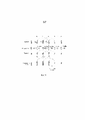
В AVC предусмотрены особые типы изображения (SI/SP), которые позволяют идентично реконструировать изображение из другого потока и, таким образом, облегчают переключение потоков. Видеоизображения, таким образом, кодируются в точках переключения в SP-изображения, а не в изображения, кодированные с внутренним предсказанием, как изображено на фиг. 3. Эффективность кодирования SP-изображений выше, чем для изображений, кодированных с внутренним предсказанием, но они все же менее эффективны, чем обычные P-изображения. Поэтому общая эффективность кодирования все же снижается в случае назначения большого количества точек переключения.AVC provides special image types (SI/SP) that allow an image to be identically reconstructed from another stream and thus facilitate stream switching. The video images are thus encoded at the switch points into SP pictures rather than into intra prediction encoded pictures as depicted in FIG. 3. The coding efficiency of SP pictures is higher than that of intra prediction encoded pictures, but they are still less efficient than normal P pictures. Therefore, the overall coding efficiency is still reduced if a large number of switching points are assigned.
В документе автора Zhou и др. под названием “Efficient bit stream switching of H.264 coded video”, опубликованном в Proceedings of SPIE vol. 5909 (2005), раскрыто решение, позволяющее выполнять переключение в любое время без существенных издержек по битовой скорости. Решение обеспечено только для GOP-структуры IPPP. Помимо нескольких версий одной и той же видеопоследовательности на разной битовой скорости, изображение DIFF кодируется для реконструированного опорного изображения текущего изображения, на котором происходит переключение, как изображено на фиг. 4. Изображение DIFF является разностью реконструированного опорного изображения текущего изображения и соответствующего по времени изображения в другом потоке. Разностное изображение передается на декодер для компенсации рассогласования. Поскольку изображение DIFF передается только когда происходит переключение, как упомянуто на странице 5 документа, издержки по битовой скорости, вносимые вышеописанной схемой, малы. С другой стороны, решение пригодно только для P-изображения, предсказываемого из единичного реконструированного опорного изображения. Кроме того, это решение требует, чтобы порядок кодирования и порядок отображения были идентичны.In a paper by Zhou et al. titled “ Efficient bit stream switching of H.264 coded video ”, published in Proceedings of SPIE vol. 5909 (2005), a solution is disclosed that allows switching at any time without significant bit rate overhead. The solution is provided only for the IPPP GOP structure. In addition to multiple versions of the same video sequence at different bit rates, a DIFF picture is encoded for the reconstructed reference picture of the current picture on which the switch occurs, as shown in FIG. 4. The DIFF image is the difference between the reconstructed reference image of the current image and the time-corresponding image in the other stream. The difference image is sent to the decoder to compensate for the mismatch. Since the DIFF image is only transmitted when a switch occurs, as mentioned on page 5 of the document, the bit rate overhead introduced by the above scheme is small. On the other hand, the solution is only valid for a P-picture predicted from a single reconstructed reference picture. Also, this solution requires that the encoding order and the display order are identical.
3. Сущность изобретения3. The essence of the invention
Раскрыт способ декодирования блока изображения. Способ содержит:A method for decoding an image block is disclosed. The method contains:
- декодирование, по меньшей мере, одного потока S_diff в декодированные данные и в одну информацию для идентификации реконструированного опорного изображения в буфере изображений декодера;decoding at least one S_diff stream into decoded data and into one information to identify the reconstructed reference picture in the decoder picture buffer;
- реконструкция особого опорного изображения из, по меньшей мере, идентифицированного реконструированного опорного изображения и из декодированных данных;- reconstructing the particular reference picture from at least the identified reconstructed reference picture and from the decoded data;
- реконструкция блока изображения из, по меньшей мере, особого опорного изображения, причем особое опорное изображение, будучи реконструировано, не отображается.- reconstruction of the image block from at least a specific reference image, wherein the specific reference image, being reconstructed, is not displayed.
В предпочтительном варианте, идентифицированное реконструированное опорное изображение декодируется из первого слоя, и при этом декодированные данные и информация, идентифицирующая реконструированное опорное изображение в буфере изображений декодера декодируются из второго слоя в зависимости от первого слоя.Preferably, the identified reconstructed reference picture is decoded from the first layer, whereby decoded data and information identifying the reconstructed reference picture in the decoder picture buffer are decoded from the second layer depending on the first layer.
Согласно частной характеристике, первый слой является базовым слоем.According to a private characteristic, the first layer is the base layer.
Согласно частному варианту осуществления, способ декодирования дополнительно содержит декодирование флага, указывающего, что последующие декодированные изображения второго слоя не используют никакого межслоевого предсказания.According to a particular embodiment, the decoding method further comprises decoding a flag indicating that subsequent decoded images of the second layer do not use any interlayer prediction.
Раскрыт также способ кодирования блока изображения. Способ кодирования дополнительно содержит:A method for encoding an image block is also disclosed. The encoding method further comprises:
- кодирование блока изображения из, по меньшей мере, одного реконструированного опорного изображения; и- encoding an image block from at least one reconstructed reference image; And
- кодирование, по меньшей мере, одного реконструированного опорного изображения как особого опорного изображения из другого реконструированного опорного изображения и информации для идентификации другого реконструированного опорного изображения в буфере изображений декодера, причем особое опорное изображение, будучи реконструировано, не отображается.- encoding at least one reconstructed reference picture as a specific reference picture from another reconstructed reference picture and information for identifying the other reconstructed reference picture in the decoder's picture buffer, wherein the specific reference picture, being reconstructed, is not displayed.
В предпочтительном варианте, идентифицированное реконструированное опорное изображение, кодируется в первом слое и, по меньшей мере, одно реконструированное опорное изображение и информация для идентификации другого реконструированного опорного изображения в буфере изображений декодера кодируются во втором слое в зависимости от первого слоя.Preferably, the identified reconstructed reference picture is encoded in the first layer and at least one reconstructed reference picture and information for identifying another reconstructed reference picture in the decoder picture buffer is encoded in the second layer depending on the first layer.
Согласно частной характеристике, первый слой является базовым слоем.According to a private characteristic, the first layer is the base layer.
Согласно частному варианту осуществления, дополнительно содержится кодирование флага, указывающего, что последующие кодированные изображения второго слоя не используют никакого межслоевого предсказания.According to a particular embodiment, the encoding of a flag is further included indicating that subsequent encoded pictures of the second layer do not use any interlayer prediction.
Устройство декодирования для декодирования блока изображения раскрыто. Устройство декодирования содержит:A decoding device for decoding an image block is disclosed. The decoding device contains:
- средство для декодирования, по меньшей мере, одного потока S_diff в декодированные данные и в одну информацию для идентификации реконструированного опорного изображения в буфере изображений декодера;means for decoding at least one S_diff stream into decoded data and into one information for identifying a reconstructed reference picture in a decoder picture buffer;
- средство для реконструкции особого опорного изображения из, по меньшей мере, идентифицированного реконструированного опорного изображения и из декодированных данных;means for reconstructing the particular reference picture from at least the identified reconstructed reference picture and from the decoded data;
- средство для реконструкции блока изображения из, по меньшей мере, особого опорного изображения, причем, по меньшей мере, особое опорное изображение не отображается.means for reconstructing the image block from at least the specific reference image, wherein at least the specific reference image is not displayed.
Устройство декодирования выполнено с возможностью выполнения этапов способа декодирования.The decoding device is configured to perform the steps of the decoding method.
Устройство кодирования для кодирования блока изображения раскрыто. Устройство кодирования содержит:An encoding device for encoding an image block is disclosed. The encoding device contains:
- кодирование блока изображения из, по меньшей мере, одного реконструированного опорного изображения; и- encoding an image block from at least one reconstructed reference image; And
- кодирование, по меньшей мере, одного реконструированного опорного изображения как особого опорного изображения из другого реконструированного опорного изображения и информации для идентификации другого реконструированного опорного изображения в буфере изображений декодера, причем особое опорное изображение, будучи реконструировано, не отображается.- encoding at least one reconstructed reference picture as a specific reference picture from another reconstructed reference picture and information for identifying the other reconstructed reference picture in the decoder's picture buffer, wherein the specific reference picture, being reconstructed, is not displayed.
Устройство кодирования выполнено с возможностью выполнения этапов способа кодирования.The encoding device is configured to perform the steps of the encoding method.
Наконец, раскрыт поток данных. Поток данных содержит кодированную в нем одну информацию для идентификации реконструированного опорного изображения в буфере изображений декодера и данные, обеспечивающие возможность реконструкции особого опорного изображения из идентифицированного реконструированного опорного изображения, причем особое опорное изображение является опорным изображением, которое не отображается.Finally, the data stream is revealed. The data stream contains encoded therein one information for identifying the reconstructed reference picture in the decoder picture buffer and data enabling the reconstruction of the particular reference picture from the identified reconstructed reference picture, the particular reference picture being a reference picture which is not displayed.
4. Краткое описание чертежей4. Brief description of the drawings
Другие признаки и преимущества изобретения явствуют из нижеследующего описания некоторых его вариантов осуществления, причем это описание приведено со ссылками на чертежи в которых:Other features and advantages of the invention appear from the following description of some of its embodiments, and this description is given with reference to the drawings in which:
фиг. 1 и 2 демонстрируют общие принципы переключения потоков;fig. 1 and 2 demonstrate the general principles of thread switching;
фиг. 3 демонстрирует принципы переключения потоков с использованием SI/SP-изображений согласно уровню техники;fig. 3 shows principles of stream switching using SI/SP images according to the prior art;
фиг. 4 демонстрирует принципы переключения потоков с использованием изображения DIFF согласно уровню техники;fig. 4 shows principles of stream switching using a DIFF image according to the prior art;
фиг. 5 изображает блок-схему операций способа декодирования согласно изобретению;fig. 5 is a flowchart of the decoding method according to the invention;
фиг. 6 изображает блок-схему операций способа кодирования согласно изобретению;fig. 6 shows a flowchart of the coding method according to the invention;
фиг. 7 демонстрирует принципы переключения потоков с использованием SRP-изображений согласно изобретению;fig. 7 shows the principles of stream switching using SRP images according to the invention;
фиг. 8 демонстрирует дополнительный вариант осуществления способа декодирования согласно изобретению;fig. 8 shows a further embodiment of the decoding method according to the invention;
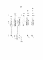
фиг. 9 изображает кодер многослойного видео согласно изобретению;fig. 9 shows a layered video encoder according to the invention;
фиг. 10 изображает декодер многослойного видео согласно изобретению; иfig. 10 shows a layered video decoder according to the invention; And
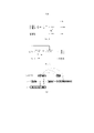
фиг. 11 представляет многослойный поток согласно изобретению.fig. 11 represents a multilayer flow according to the invention.
5. Подробное описание изобретения5. Detailed description of the invention
Изобретение относится к способу декодирования блока изображения, состоящего из пикселей, и к способу кодирования такого блока изображения. Блок изображения принадлежит изображению из последовательности изображений. Каждое изображение содержит пиксели или точки изображение, с каждым(ой) из которых связан, по меньшей мере, один элемент данных изображения. Элементом данных изображения является, например, элемент данных яркости или элемент данных цветности. Способы кодирования и декодирования описаны ниже со ссылкой на блок изображения. Ясно, что эти способы можно применять на нескольких блоках изображения для изображения и на нескольких изображениях последовательности с целью кодирования, соответственно декодирования, одного или более изображений. Блок изображения представляет собой набор пикселей любой формы. Это может быть квадрат, прямоугольник. Но изобретение не ограничивается такими формами. В нижеследующем разделе слово "блок" используется в смысле "блок изображения". В HEVC блок означает единицу кодирования (CU).The invention relates to a method for decoding an image block consisting of pixels, and to a method for encoding such an image block. An image block belongs to an image from an image sequence. Each image contains image pixels or dots, each of which has at least one image data element associated with it. The image data element is, for example, a luminance data element or a chrominance data element. The encoding and decoding methods are described below with reference to an image block. It is clear that these methods can be applied on several image blocks for an image and on several images of a sequence for the purpose of encoding, respectively decoding, one or more images. An image block is a collection of pixels of any shape. It can be a square, a rectangle. But the invention is not limited to such forms. In the following section, the word "block" is used in the sense of "image block". In HEVC, a block means a coding unit (CU).
Термин “предсказатель” означает данные, используемые для предсказания других данных. Предсказатель используется для предсказания блока изображения. Предсказатель или блок предсказания получается из одной или нескольких реконструированных опорных выборок того же изображения, что и изображение, которому принадлежит блок, которые он предсказывает (пространственное предсказание или предсказание внутри изображения) или из одного (однонаправленное предсказание) или нескольких опорных блоков (двунаправленное предсказание или би-предсказание) реконструированных опорных изображений (временное предсказание или предсказание между изображениями). Опорный блок идентифицируется в реконструированном опорном изображении вектором движения. Предсказание также может взвешиваться для учета модели изменения освещения (известной как взвешенное предсказание).The term “predictor” means data used to predict other data. The predictor is used to predict a block of an image. A predictor or prediction block is obtained from one or more reconstructed reference samples of the same image as the image to which the block belongs, which it predicts (spatial or intra-picture prediction) or from one (unidirectional prediction) or more reference blocks (bidirectional or bi-prediction) of the reconstructed reference pictures (temporal or inter-picture prediction). The reference block is identified in the reconstructed reference image by a motion vector. The prediction can also be weighted to account for a lighting change model (known as weighted prediction).
Термин “остаток” означает данные, полученные после вычитания предсказателя из исходных данных.The term "residual" means the data obtained after subtracting the predictor from the original data.
Термин “реконструкция” означает данные (например, пиксели, блоки), полученные после объединения остатка с предсказателем. Объединение, в общем случае, представляет собой сумму предсказателя с остатком. Однако объединение является более общим и, в особенности, содержит дополнительный постфильтрационный каскад реконструированных выборок и/или дополнительный этап добавления смещений к реконструированным выборкам. После реконструкции опорного изображения, оно сохраняется в DPB (расшифровывается как "буфер изображений декодера") как вновь реконструированное опорное изображение.The term "reconstruction" means the data (eg, pixels, blocks) obtained after combining the remainder with the predictor. The union, in general, is the sum of the predictor with the remainder. However, the pooling is more general and, in particular, contains an additional post-filtering cascade of reconstructed samples and/or an additional step of adding biases to the reconstructed samples. After the reference picture has been reconstructed, it is stored in the DPB (stands for Decoder Picture Buffer) as a newly reconstructed reference picture.
В отношении декодирования изображений, термины "реконструкция" (восстановление) и "декодирование" очень часто используются как синонимы. Поэтому "реконструированный блок" также можно понимать в смысле "декодированный блок".With respect to image decoding, the terms "reconstruction" (restoration) and "decoding" are very often used interchangeably. Therefore, "reconstructed block" can also be understood in the sense of "decoded block".
Термин "кодирование" следует понимать в самом широком смысле. Кодирование, возможно, содержит применение преобразования и/или квантования данных. Оно также может означать только энтропийное кодирование. Примером такого преобразования DCT является ("дискретное косинусное преобразование). Таким же образом, термин "декодирование", возможно, содержит, помимо энтропийного декодирования, применение преобразования и/или обратного квантования. Преобразование, применяемое на стороне декодера, является преобразованием, обратным применяемому на стороне кодера.The term "encoding" should be understood in its broadest sense. Encoding may include applying a transformation and/or quantization of the data. It can also mean only entropy coding. An example of such a DCT transformation is ("discrete cosine transform"). In the same way, the term "decoding" may contain, in addition to entropy decoding, the application of a transformation and/or inverse quantization. The transformation applied at the decoder side is the inverse transformation applied at side of the encoder.
Поток представляет последовательность битов, которая формирует представление кодированных изображений, и соответствующие данные, образующие одну или более кодированных видеопоследовательностей. Поток является коллективным термином, используемым для обозначения либо потока единиц NAL, либо потока байтов.A stream represents a sequence of bits that forms a representation of encoded pictures, and corresponding data that forms one or more encoded video sequences. Stream is a collective term used to refer to either a stream of NAL units or a stream of bytes.
Единица NAL (расшифровывается как “уровень сетевых абстракций”) является синтаксической структурой, содержащей указание типа данных, которому нужно следовать, и байты, содержащие эти данные. NAL указывается для форматирования этих данных и обеспечения информации заголовка способом, пригодным для транспортировки на различных каналах связи или носителях данных. Все данные содержатся в единицах NAL, каждая из которых содержит целое число байтов. Единица NAL указывает общий формат для использования в пакетно-ориентированных и потоковых системах. Формат единиц NAL для пакетно-ориентированного переноса и потока байтов одинаков за исключением того, что в формате потока байтов каждой единице NAL может предшествовать префикс начального кода и дополнительные байты заполнения.A NAL unit (stands for “Network Abstraction Layer”) is a syntactic structure containing an indication of the data type to be followed and the bytes containing this data. NAL is specified to format this data and provide header information in a manner suitable for transport on various communication channels or storage media. All data is contained in NAL units, each of which contains an integer number of bytes. The NAL unit specifies the general format for use in packet-oriented and streaming systems. The format of NAL units for packet-oriented transfer and byte stream is the same except that in byte stream format, each NAL unit may be preceded by a start code prefix and additional padding bytes.
AU (расшифровывается как “единица доступа”) представляет собой набор единиц NAL, связанных друг с другом согласно заданному правилу классификации, которые располагаются последовательно в порядке декодирования и содержат в точности одно кодированное изображение. Декодирование единицы доступа всегда дает декодированное изображение.AU (stands for “access unit”) is a set of NAL units associated with each other according to a given classification rule, which are sequential in decoding order and contain exactly one encoded picture. Decoding an access unit always yields a decoded picture.
Блоки, представленные на фиг. 5 и 6, являются чисто функциональными сущностями, которые не обязательно соответствуют физически разделенным сущностям. Как очевидно специалисту в данной области техники, аспекты настоящих принципов можно реализовать в виде системы, способа или компьютерно-считываемого носителя. Соответственно, аспекты настоящих принципов могут принимать форму полностью аппаратного варианта осуществления, полностью программный вариант осуществления (включающий в себя программно-аппаратное обеспечение, резидентное программное обеспечение, микрокод и т.д.), или вариант осуществления, объединяющий программные и аппаратные аспекты, которые все в общем случае именуются здесь “схемой”, “модулем” или “системой”. Кроме того, аспекты настоящих принципов может принимать форму компьютерно-считываемого носителя данных. Можно использовать любую комбинацию одного или более компьютерно-считываемых носителей данных.The blocks shown in Fig. 5 and 6 are purely functional entities that do not necessarily correspond to physically separated entities. As one of skill in the art would appreciate, aspects of the present principles may be implemented in a system, method, or computer-readable medium. Accordingly, aspects of these principles may take the form of an all-hardware implementation, an all-software implementation (including firmware, resident software, microcode, etc.), or an implementation that combines software and hardware aspects that are all are generally referred to here as a “circuit”, “module”, or “system”. In addition, aspects of the present principles may take the form of a computer-readable storage medium. Any combination of one or more computer-readable storage media may be used.
Блок-схема операций и/или блок-схемы, показанные на фигурах, демонстрируют конфигурацию, принцип работы и функциональные возможности возможных реализаций систем, способов и компьютерных программных продуктов согласно различным вариантам осуществления настоящего изобретения. В связи с этим, каждый блок в блок-схеме операций или блок-схемах может представлять модуль, сегмент или участок кода, который содержит одну или более исполнимых инструкций для реализации заданной(ых) логической(их) функции(й). Следует также заметить, что, в некоторых альтернативных реализациях, функции, указанные в блоке, могут осуществляться в другом порядке, чем указано на фигурах. Например, два блока, показанные последовательно, могут, фактически, выполняться, по существу, одновременно, или блоки могут иногда выполняться в обратном порядке, или блоки могут выполняться в альтернативном порядке, в зависимости от предусмотренных функциональных возможностей. Также будет указано, что каждый блок блок-схем и/или иллюстрации блок-схемы операций, и комбинации блоков в блок-схемах и/или иллюстрации блок-схемы операций, можно реализовать посредством аппаратных систем специального назначения, которые осуществляют заданные функции или действия, или комбинации оборудования специального назначения и компьютерных инструкций. Хотя в явном виде не описано, настоящие варианты осуществления можно применять в любой комбинации или подкомбинации.The flowchart and/or block diagrams shown in the figures demonstrate the configuration, operation, and functionality of possible implementations of systems, methods, and computer program products according to various embodiments of the present invention. In this regard, each block in the flowchart or flowcharts may represent a module, segment, or section of code that contains one or more executable instructions for implementing the given logical function(s). It should also be noted that, in some alternative implementations, the functions indicated in the block may be performed in a different order than indicated in the figures. For example, two blocks shown in sequence may actually be executed substantially simultaneously, or the blocks may sometimes be executed in reverse order, or the blocks may be executed in an alternate order, depending on the functionality provided. It will also be noted that each block of flowcharts and/or flowchart illustrations, and combinations of blocks in the flowchart and/or flowchart illustration, can be implemented by special purpose hardware systems that perform predetermined functions or actions, or combinations of special purpose equipment and computer instructions. Although not explicitly described, the present embodiments may be used in any combination or subcombination.
Фиг. 5 изображает блок-схему операций способа декодирования согласно конкретному и неограничительному варианту осуществления. Способ предусматривает декодирование текущего блока Bc изображения, кодированного в потоке S. Блок Bc изображения принадлежит слайсу Sc текущего изображения Ic. Слайс входит в состав изображения, например набора блоков изображения.Fig. 5 is a flowchart of a decoding method according to a specific and non-restrictive embodiment. The method involves decoding the current image block Bc encoded in the stream S. The image block Bc belongs to the slice Sc of the current image Ic. A slice is part of an image, such as a set of image blocks.
На этапе 10, по меньшей мере, один поток S_diff декодируется в декодированные данные (например, остатки и режимы кодирования) и в информацию INFO для идентификации реконструированного опорного изображения R2, хранящегося в DPB.In
На этапе 12, особое опорное изображение (сокращенно SRP) R1’ реконструируется из идентифицированного реконструированного опорного изображения R2 и из декодированных данных. Затем особое опорное изображение помещается в DPB. Это опорное изображение R1’ является особым, поскольку оно никогда не отображается, но используются только для реконструкции блоков в других изображениях. Реконструкция SRP R1’ содержит, для каждого блока изображения R1’, определение предсказателя и добавление остатка. Предсказатель можно определить из идентифицированного реконструированного опорного изображения R2 (либо в качестве блока в R2, совмещенном с Bc, или в качестве блока, подвергнутого компенсации движения, в R2, таким образом, идентифицированном вектором движения) или из соседних реконструированных выборок R1’, как в классическом внутреннем предсказании. Блок в R2 совмещен с Bc, если его пространственное положение в R2 идентично пространственному положению Bc в Ic. Согласно варианту, если размер реконструированного опорного изображения R2 отличается от размера текущего изображения Ic, то R2 повторно масштабируется для реконструкции особого опорного изображения благодаря чему, повторно масштабированное изображение R2 (возможно с надлежащим заполнением) имеет такой же размер, как Ic. В этом случае, R1’ реконструируется из F(R2), где F – фильтр повторного масштабирования. Поток S_diff может быть частью потока S или может быть независимым от потока S.In
В порядке примера, поток S_diff кодирует попиксельную разность между другим реконструированным опорным изображением R1, отличным от R2, и реконструированным опорным изображением R2. R1, например, является реконструированным опорным изображением, из которого кодируется текущий блок Bc изображения. В этом случае, декодирование потока S_diff содержит декодирование разностного изображения DIFF обычно посредством энтропийного декодирования, обратного квантования и преобразования. Преобразованием является, например, обратное DCT. Разностное изображение обычно является приближением разности между реконструированным опорным изображением R1 и реконструированным опорным изображением R2. Приближение обусловлено потерей в ходе кодирования (например, вследствие квантования). В случае беспотерьного кодирования разностного изображения DIFF, декодированное разностное изображение DIFF равно разности между реконструированным опорным изображением R1 и реконструированным опорным изображением R2. Согласно варианту, если R1 и R2 имеют разные размеры, разностное изображение является разностью между реконструированным опорным изображением R1 и повторно масштабированным реконструированным опорным изображением R2. В порядке примера, если R2 больше R1, то R2 масштабируется с понижением, и если R2 меньше R1, то R2 масштабируется с повышением. В этом случае, особое опорное изображение R1’ равно F(R2)+DIFF, F является тождественным преобразованием, если R2 и Ic имеют одинаковый размер, или, в противном случае, F является функцией повторного масштабирования.By way of example, the S_diff stream encodes a pixel-by-pixel difference between another reconstructed reference picture R1 other than R2 and a reconstructed reference picture R2. R1, for example, is a reconstructed reference picture from which the current picture block Bc is encoded. In this case, the decoding of the S_diff stream comprises decoding the DIFF difference image, usually by entropy decoding, inverse quantization, and transformation. The transformation is, for example, the inverse DCT. The difference image is typically an approximation of the difference between the reconstructed reference image R1 and the reconstructed reference image R2. Approximation is due to loss during encoding (eg due to quantization). In the case of lossless encoding of the DIFF difference picture, the decoded DIFF difference picture is equal to the difference between the reconstructed reference picture R1 and the reconstructed reference picture R2. In an embodiment, if R1 and R2 have different sizes, the difference image is the difference between the reconstructed reference image R1 and the rescaled reconstructed reference image R2. By way of example, if R2 is greater than R1, then R2 is scaled down, and if R2 is less than R1, then R2 is scaled up. In this case, the specific reference image R1' is equal to F(R2)+DIFF, F is the identity transform if R2 and Ic are the same size, or otherwise F is the rescaling function.
Согласно варианту, способ декодирования дополнительно содержит необязательное декодирование знака, связанного с разностным изображением DIFF. Если такой знак декодируется, особое опорное изображение R1’ равно F(R2)+DIFF, когда знак положителен, и равно F(R2)-DIFF, когда знак отрицателен.According to an embodiment, the decoding method further comprises optionally decoding a sign associated with a DIFF difference image. If such a character is decoded, the specific reference picture R1' is equal to F(R2)+DIFF when the sign is positive and equal to F(R2)-DIFF when the sign is negative.
Согласно другому варианту, поток S_diff кодирует для некоторых блоков R1 разность между этими блоками и совмещенными блоками в R2. Другие блоки R1 кодируются в S_diff с использованием классического внутреннего предсказания, т.е. из соседних реконструированных выборок.According to another variant, the S_diff stream encodes, for some R1 blocks, the difference between these blocks and the aligned blocks in R2. The other R1 blocks are encoded in S_diff using classical intra prediction, i.e. from neighboring reconstructed samples.
Согласно другому варианту, поток S_diff кодирует для некоторых блоков R1 разность между этими блоками и соответствующими блоками в R2. Соответствующие блоки в R2 являются либо совмещенными блоками, либо блоками, подвергнутыми компенсации движения. Другие блоки R1 кодируются в S_diff с использованием классического внутреннего предсказания, т.е. из соседних реконструированных выборок.According to another variant, the flow S_diff encodes for some blocks R1 the difference between these blocks and the corresponding blocks in R2. The corresponding blocks in R2 are either aligned blocks or blocks subjected to motion compensation. The other R1 blocks are encoded in S_diff using classical intra prediction, i.e. from neighboring reconstructed samples.
Декодирование информации INFO позволяет обрабатывать разные случаи использования. В порядке примера, если текущий блок Bc изображения кодируется из двух реконструированных опорных изображений R1 и r1, то два особых опорных изображения R1’ и r1’ и две информация INFO и info декодируются на этапе 10. Особые опорные изображения R1’ и r1’ соответствуют, соответственно, R2 и r2, где R2 и r2 – два реконструированных опорных изображения, хранящиеся в DPB, откуда Bc подлежит реконструкции. В результате, INFO указывает декодеру, что R1’ подлежит реконструкции из R2, тогда как info указывает, что r1’ подлежит реконструкции из r2.Decoding the INFO information allows handling different use cases. By way of example, if the current picture block Bc is encoded from two reconstructed reference pictures R1 and r1, then two specific reference pictures R1' and r1' and two information INFO and info are decoded in
Каждое особое изображение идентифицируется, например, в потоке S_diff выделенным флагом, указывающим тип изображения/слайса, отличный от классического типа изображения/слайса I, P, B. Этот тип изображения/слайса указывает, что текущая AU содержит особое опорное изображение, которое не отображается. Согласно варианту, каждое особое изображение идентифицируется выделенным флагом в заголовке слайса.Each particular picture is identified, for example, in the S_diff stream by a dedicated flag indicating a picture/slice type other than the classic picture/slice type I, P, B. This picture/slice type indicates that the current AU contains a particular reference picture that is not displayed. . In a variant, each particular image is identified by a dedicated flag in the slice header.
Согласно варианту, типом слайса изображения является I, P или B, но особый флаг в заголовке слайса указывает, что реконструированное изображение не отображается, но сохраняется как опорное в DPB.In a variant, the image slice type is I, P, or B, but a specific flag in the slice header indicates that the reconstructed image is not displayed but stored as a reference in the DPB.
Информация INFO для идентификации в DPB реконструированного опорного изображения R2, представляет собой, например, POC (расшифровывается как “счетчик порядка изображений”), определенный в документе ISO/IEC 14496-10 (раздел 3.104). Согласно варианту, информация для идентификации реконструированного опорного изображения является индексом реконструированного опорного изображения.The INFO information for identifying in the DPB the reconstructed reference picture R2 is, for example, POC (stands for “picture order counter”) as defined in ISO/IEC 14496-10 (section 3.104). In an embodiment, the information for identifying the reconstructed reference image is an index of the reconstructed reference image.
На этапе 16, текущий блок Bc изображения реконструируется из особого опорного изображения R1’. Обычно, поскольку особое опорное изображение ближе в отношении содержимого к R1, чем R2, дрейф уменьшается. Обычно, реконструкция блока изображения содержит декодирование остатка из потока S и добавление остатка в предсказатель. Остаток может быть нулевым в случае режима пропуска. Декодирование остатка содержит энтропийное декодирование, обратное квантование и применение преобразования, обратного преобразованию, применяемому на стороне кодера. Эти этапы общеизвестны специалистам в области сжатия/кодирования видеосигнала и дополнительно не раскрыты. Опорный блок в особом опорном изображении R1’ идентифицируется вектором движения, декодированным из потока S. Опорный блок используется в качестве предсказателя. В случае би-предсказания, два опорных блока идентифицируются в двух реконструированных опорных изображениях, которые, возможно, являются одним и тем же реконструированным опорным изображением. Предсказатель представляет собой взвешенную сумму этих двух опорных блоков. Если Bc би-предсказывается из двух опорных блоков, принадлежащих двум реконструированным опорным изображениям R2 и r2, которые могут отличаться от реконструированных опорных изображений R1 и r1, используемых при кодировании, то два SRP R1’ и r1’ можно реконструировать. Таким образом, особые опорные изображения R1’ и r1’ используются как опорные изображения для Bc. Bc также может быть реконструирован из одного особого опорного изображения R1’ и из r1, если r1 доступно в DPB при реконструкции Bc. INFO и знак можно декодировать для каждого особого опорного изображения (в заголовке слайса или в заголовке сегмента слайса) или можно группировать для нескольких особых опорных изображений в одном единственном заголовке. INFO и знак декодируются, например, из сообщения SEI, VPS (набора параметров видео HEVC) или из заголовка слайса Sc.In
Фиг. 6 изображает блок-схему операций способа кодирования согласно конкретному и неограничительному варианту осуществления. Способ позволяет кодировать текущий блок Bc изображения в потоке S.Fig. 6 is a flowchart of an encoding method according to a specific and non-restrictive embodiment. The method allows encoding the current image block Bc in the stream S.
На этапе 20, текущий блок Bc изображения кодируется из, по меньшей мере, одного первого реконструированного опорного изображения R1 в потоке S. Обычно кодирование текущего блока изображения содержит определение остатка, преобразование остатка и квантование преобразованного остатка в квантованные данные. Квантованные данные дополнительно подвергаются энтропийному кодированию в потоке S. Остаток получается вычитанием предсказателя из текущего блока Bc изображения. Предсказатель определяется из первого реконструированного опорного изображения R1. Точнее говоря, предсказатель определяется в реконструированном опорном изображении R1 на основании вектора движения. Если текущий блок би-предсказывается из двух опорных блоков, предсказатель получается усреднением этих двух опорных блоков. Два опорных блока принадлежат либо двум разным реконструированным опорным изображениям R1 и r1, либо одному и тому же реконструированному опорному изображению. Векторы движения также кодируются в потоке S. Эти этапы общеизвестны специалистам в области сжатия видеосигнала и дополнительно не раскрыты.In
На этапе 24, реконструированное опорное изображение R1 и информация INFO кодируются в поток S_diff. Декодирование S_diff дает SRP. Поток S_diff может быть частью потока S или может быть независимым от потока S. Реконструированное опорное изображение R1 кодируется в S_diff из второго реконструированного опорного изображения R2, отличного от R1, идентифицируемого INFO. Согласно варианту, если размер реконструированного опорного изображения R2 отличается от размера текущего изображения Ic и, таким образом, от размера R1, то R2 повторно масштабируется для кодирования реконструированного опорного изображения R1, благодаря чему, повторно масштабированное изображение R2 (возможно с надлежащим заполнением) имеет такой же размер, как Ic. В этом случае, R1 кодируется из F(R2), где F – фильтр повторного масштабирования.In
В порядке примера, поток S_diff кодирует попиксельную разность DIFF между R1 и R2. Изображение DIFF кодируется посредством преобразования (например, с использованием DCT), квантования и энтропийного кодирования. Согласно варианту, если R1 и R2 имеют разные размеры, разностное изображение является разностью между реконструированным опорным изображением R1 и повторно масштабированным вторым реконструированным опорным изображением R2. В порядке примера, если R2 больше R1, то R2 масштабируется с понижением, и если R2 меньше R1, то R2 масштабируется с повышением. В этом случае, DIFF=R1-F(R2), F является тождественной функцией, когда R2 и Ic имеют одинаковый размер, и в противном случае является функцией повторного масштабирования.By way of example, the S_diff stream encodes a pixel-by-pixel difference DIFF between R1 and R2. A DIFF image is encoded through transformation (eg, using DCT), quantization, and entropy coding. In an embodiment, if R1 and R2 have different sizes, the difference image is the difference between the reconstructed reference image R1 and the rescaled second reconstructed reference image R2. By way of example, if R2 is greater than R1, then R2 is scaled down, and if R2 is less than R1, then R2 is scaled up. In this case, DIFF=R1-F(R2), F is the identity function when R2 and Ic have the same size, and otherwise is the rescaling function.
Согласно варианту, способ декодирования дополнительно содержит необязательное декодирование знака, связанного с разностным изображением. Если такой знак декодируется, особое опорное изображение R1’ равно F(R2)+DIFF, когда знак положителен, и равно F(R2)-DIFF, когда знак отрицателен.According to an embodiment, the decoding method further comprises optionally decoding a sign associated with a difference image. If such a character is decoded, the specific reference picture R1' is equal to F(R2)+DIFF when the sign is positive and equal to F(R2)-DIFF when the sign is negative.
Согласно другому варианту, поток S_diff кодирует для некоторых блоков R1 разность между этими блоками и блоками в R2 (т.е. либо блоками, совмещенными с Bc, либо с блоками, подвергнутыми компенсации движения). Другие блоки R1 кодируются в S_diff с использованием классического внутреннего предсказания, т.е. из соседних реконструированных выборок.According to another variant, the flow S_diff encodes for some blocks R1 the difference between these blocks and blocks in R2 (ie either blocks aligned with Bc or blocks subjected to motion compensation). The other R1 blocks are encoded in S_diff using classical intra prediction, i.e. from neighboring reconstructed samples.
Кодирование информации INFO позволяет обрабатывать другой случай использования. В порядке примера, если текущий блок Bc изображения кодируется из двух реконструированных опорных изображений R1 и r1, то два реконструированных опорных изображения кодируются из двух других реконструированных опорных изображений R2 и r2. INFO указывает декодеру, что особое опорное изображение R1’ подлежит реконструкции из R2, тогда как info указывает, что другое особое опорное изображение r1’ подлежит реконструкции из r2. Каждое особое опорное изображение идентифицируется, например, в потоке S_diff выделенным флагом, указывающим тип изображения/слайса, отличный от классического типа изображения/слайса I, P, B. Этот тип изображения/слайса указывает, что текущая AU является особым опорным изображением, который подлежит использованию для замены изображения в DPB. Согласно варианту, каждое особое изображение идентифицируется выделенным флагом в заголовке слайса.Encoding the INFO information allows a different use case to be handled. By way of example, if the current picture block Bc is encoded from two reconstructed reference pictures R1 and r1, then the two reconstructed reference pictures are encoded from two other reconstructed reference pictures R2 and r2. INFO indicates to the decoder that the specific reference picture R1' is to be reconstructed from R2, while info indicates that the other specific reference picture r1' is to be reconstructed from r2. Each particular reference picture is identified, for example, in the S_diff stream by a dedicated flag indicating a picture/slice type other than the classic I, P, B picture/slice type. This picture/slice type indicates that the current AU is a particular reference picture to be use to replace an image in DPB. In a variant, each particular image is identified by a dedicated flag in the slice header.
Согласно варианту, типом слайса изображения является I, P или B, но особый флаг в заголовке слайса указывает, что реконструированное изображение не отображается, но сохраняется как опорное в DPB.In a variant, the image slice type is I, P, or B, but a specific flag in the slice header indicates that the reconstructed image is not displayed but stored as a reference in the DPB.
В конкретном варианте осуществления, одно особое опорное изображение и информация INFO кодируются для нескольких или каждой из возможных пар реконструированного опорного изображения DPB. В результате, блок Bc можно в любое время реконструировать из любого изображения DPB, даже если оно не является изображением, из которого он был кодирован, в то же время, ограничивая дрейф. Действительно, при реконструкции Bc, если R1 недоступен в DPB, Bc можно реконструировать из особого опорного изображения R1’ вместо R2. Таким образом, дрейф ограничивается, поскольку R1’ ближе в отношении содержимого к R1, чем R2.In a particular embodiment, one particular reference picture and INFO information are encoded for several or each of the possible pairs of the reconstructed DPB reference picture. As a result, block Bc can be reconstructed at any time from any DPB picture, even if it is not the picture from which it was encoded, while limiting drift. Indeed, when reconstructing Bc, if R1 is not available in the DPB, Bc can be reconstructed from the specific reference image R1' instead of R2. Thus drift is limited because R1' is closer in content to R1 than R2.
Информация, идентифицирующая второе реконструированное опорное изображение, представляет собой, например, POC. Согласно варианту, информация, идентифицирующая второе реконструированное опорное изображение, является индексом реконструированного опорного изображения.Information identifying the second reconstructed reference image is, for example, POC. In an embodiment, the information identifying the second reconstructed reference image is an index of the reconstructed reference image.
Все раскрытые разновидности и варианты способа декодирования применимы к способу кодирования. В частности, способ кодирования содержит необязательное кодирование знака, связанного с разностным изображением.All disclosed varieties and variations of the decoding method are applicable to the encoding method. In particular, the encoding method comprises optionally encoding a sign associated with a difference image.
INFO и знак декодируются, например, из сообщения SEI, VPS (набора параметров видео HEVC) или из заголовка слайса Sc.INFO and sign are decoded, for example, from the SEI message, VPS (HEVC Video Parameter Set) or from the slice header Sc.
Согласно варианту, способы кодирования и декодирования используются в отношении переключения потоков, как показано на фиг. 7. В этом случае, первая последовательность изображений кодируется в потоке S0. Вторая последовательность изображений кодируется в потоке S1. Обычно вторая последовательность изображений идентична первой последовательности, но кодирована на другой битовой скорости, т.е. с использованием другого шага квантования. Согласно варианту, вторая последовательность изображений является повторно масштабированной версией первой последовательности, т.е. либо масштабированной с повышением, либо масштабированной с понижением версией. Согласно конкретному варианту осуществления, S0 и S1 имеют одинаковую GOP-структуру (т.е. такой же порядок декодирования и такие же списки опорных изображений, как определенные в разделах 8.3.1 и 8.3.2 стандарта HEVC).According to an embodiment, encoding and decoding methods are used in relation to stream switching, as shown in FIG. 7. In this case, the first sequence of pictures is encoded in the stream S0. The second sequence of pictures is encoded in stream S1. Typically, the second sequence of pictures is identical to the first sequence, but encoded at a different bit rate, i.e. using a different quantization step. According to a variant, the second sequence of images is a rescaled version of the first sequence, i. e. either an upscaled or downscaled version. According to a particular embodiment, S0 and S1 have the same GOP structure (ie, the same decoding order and the same reference picture lists as defined in sections 8.3.1 and 8.3.2 of the HEVC standard).
Помимо потоков S0 и S1, в каждый момент времени tn реконструированное опорное изображение ![]()
![]()
![]()
![]()
![]()
![]()
![]()
![]()
![]()
![]()
![]()
![]()
Способ декодирования, раскрытый со ссылкой на фиг. 5, используется для декодирования блока Bc изображения после переключения из первого потока S0 во второй поток S1. Согласно фиг. 7, изображения декодируются и отображаются из потока S0 до времени t2. Переключение происходит между t2 и t3. После переключения изображения декодируются и отображаются из потока S1. Во время переключения DBP0 содержит несколько реконструированных опорных изображений, декодированных из S0. DPB0 связан с S0. Согласно фиг. 7, DPB0 содержит три реконструированных опорных изображения ![]()
![]()
![]()
![]()
![]()
![]()
На этапе 10, S_diff1, S_diff2 и S_diff3 декодируются в декодированные данные (например, остатки и режимы кодирования) и в информацию info_t0, info_t1, info_t2, идентифицирующую реконструированные опорные изображения ![]()
![]()
![]()
![]()
![]()
![]()
На этапе 12, три особых опорных изображения SRP_t0, SRP_t1, SRP_t2 реконструируются из соответствующих декодированных данных и из соответствующих реконструированных опорных изображений ![]()
![]()
![]()
![]()
![]()
![]()
![]()
![]()
![]()
![]()
![]()
![]()
![]()
![]()
![]()
![]()
![]()
![]()
![]()
![]()
![]()
![]()
![]()
![]()
![]()
![]()
![]()
![]()
![]()
![]()
![]()
![]()
![]()
![]()
![]()
![]()
![]()
![]()
![]()
![]()
![]()
![]()
![]()
![]()
![]()
![]()
![]()
![]()
На этапе 16, Bc реконструируется из реконструированных опорных изображений в DPB1. Сразу после переключения, DPB1 содержит три SRP.In
Очевидно, изобретение не ограничивается случаем 3 реконструированных опорных изображений. Согласно конкретному варианту осуществления изобретения, для всех реконструированных опорных изображений в DPB0, особое опорное изображение реконструируется на этапе 12 и сохраняется в DPB1. Согласно варианту, SRP реконструируется только для каждого реконструированного опорного изображения в DPB0, которые подлежат использованию в качестве опорных изображений после переключения.Obviously, the invention is not limited to the case of 3 reconstructed reference pictures. According to a specific embodiment of the invention, for all reconstructed reference pictures in DPB0, a specific reference picture is reconstructed in
Согласно варианту, флаг f13 кодируется (соответственно, декодируется), например, в VPS или SEI, указывая, что последующие кодированные (соответственно, декодированные) изображения с данным layer_id не используют никакого межслоевого предсказания. Точнее говоря, изображения, кодированные (соответственно декодированные) после флага, не используют никакого межслоевого предсказания.In a variant, flag f13 is encoded (respectively decoded) in, for example, a VPS or SEI indicating that subsequent encoded (respectively decoded) pictures with the given layer_id do not use any interlayer prediction. More specifically, images encoded (respectively decoded) after the flag do not use any interlayer prediction.
Фиг. 8 демонстрирует дополнительный вариант осуществления способа декодирования согласно конкретному и неограничительному варианту осуществления. Декодер принимает разные единицы доступа. Принимается и декодируется первая единица доступа AU1. Первое изображение I1 реконструируется из декодированной AU1. Затем принимается и декодируется вторая единица доступа AU2. Второе изображение I2 реконструируется из декодированной AU2. Изображения I1 и I2 принадлежат одному и тому же потоку S0 и сохраняются в DPB0, если они сигнализируются как используемые в качестве опорных изображений. Затем происходит переключение. Переключение может запрашиваться декодером, который отправляет запрос кодеру для приема потока S_diff. Согласно варианту, переключение инициируется кодером. После переключения, декодер принимает две единицы AU S_diff1 и S_diff2. S_diff1 и S_diff2 (этап 10) декодируются для реконструкции (этап 12) SRP1 и SRP2 с использованием изображений I1 и I2 соответственно. SRP1 и SRP2 являются двумя особыми опорными изображениями. Затем SRP1 и SRP2 помещаются в DPB1, связанный с S1. Затем декодер принимает AU3 и декодирует ее. Изображение I3 реконструируется из декодированной AU3 и, возможно, из, по меньшей мере, одного изображения DPB1 (временное предсказание), т.е. SRP1 либо SRP2. I3 принадлежит второму потоку S1 и, возможно, хранится в DPB1 для использования в будущем в качестве реконструированного опорного изображения. Затем декодер принимает AU4 и декодирует ее. Изображение I4 реконструируется из декодированной AU4 и, возможно, из, по меньшей мере, одного изображения DPB1 (временное предсказание). Изображения I1, I2, I3 и I4 отображаются, а SRP1, SRP2 – нет. Действительно, отображается только одно из двух выровненных по времени изображений. SRP1 выровнено по времени с I1, а SRP2 выровнено по времени с I2.Fig. 8 shows a further embodiment of a decoding method according to a specific and non-limiting embodiment. The decoder accepts different access units. The first access unit AU1 is received and decoded. The first picture I1 is reconstructed from the decoded AU1. Then, the second access unit AU2 is received and decoded. The second picture I2 is reconstructed from the decoded AU2. Pictures I1 and I2 belong to the same stream S0 and are stored in DPB0 if they are signaled as being used as reference pictures. Then there is a switch. The switch may be requested by the decoder, which sends a request to the encoder to receive the S_diff stream. According to a variant, the switchover is initiated by the encoder. After switching, the decoder receives two AUs S_diff1 and S_diff2. S_diff1 and S_diff2 (step 10) are decoded to reconstruct (step 12) SRP1 and SRP2 using pictures I1 and I2, respectively. SRP1 and SRP2 are two specific reference pictures. Then SRP1 and SRP2 are placed in DPB1 associated with S1. The decoder then receives AU3 and decodes it. Image I3 is reconstructed from decoded AU3 and possibly from at least one image DPB1 (temporal prediction), i. e. SRP1 or SRP2. I3 belongs to the second stream S1 and possibly stored in DPB1 for future use as a reconstructed reference picture. The decoder then receives AU4 and decodes it. Image I4 is reconstructed from decoded AU4 and possibly from at least one image DPB1 (temporal prediction). Images I1, I2, I3 and I4 are displayed but SRP1, SRP2 are not. Indeed, only one of the two time-aligned images is displayed. SRP1 is time aligned with I1 and SRP2 is time aligned with I2.
Согласно конкретному варианту осуществления изобретения, изображения первой и второй последовательностей и особые опорные изображения кодируются в многослойный поток. В порядке конкретного примера, изображения, идентифицированные как особые опорные изображения, кодируются как слой улучшения масштабируемого потока, который зависит от другого уровня (потока S0), например базовый слой, в котором кодируются изображения первой последовательности. Первый слой зависит от второго слоя, если нуждается в информации из этого второго слоя для декодирования. Слой улучшения позволяет реконструировать из реконструированных опорных изображений S0, особые опорные изображения, подлежащие использованию в качестве опорного изображения для реконструкции изображений S1 после переключения из S0 в S1. Этот слой улучшения согласуется, например, со стандартом кодирования SVC или SHVC. Согласно конкретному варианту осуществления изобретения, особые опорные изображения кодируются поднабором инструментов/режимов кодирования, обеспечиваемых SVC или SHVC для слоя улучшения кодирования. Согласно другому варианту осуществления изобретения, внутрислоевое предсказание вектора движения (временное предсказание) отключается в стандарте кодирования SVC или SHVC. Напротив, внутреннее предсказание из слоя S0 активируется. Также может активироваться предсказание внутри изображения. Согласно другому варианту осуществления, временное предсказание mv отключается для кодирования S0 и S1, например, путем задания флага slice_temporal_mvp_enable_flag HEVC на значение "ложь". Это означает, что предсказание вектора движения (предсказание mv) строится с использованием MV из реконструированных соседних единиц кодирования, но без использования MV ранее реконструированных опорных изображений.According to a specific embodiment of the invention, the first and second sequence pictures and specific reference pictures are encoded into a layered stream. As a specific example, pictures identified as specific reference pictures are encoded as a scalable stream enhancement layer that depends on another layer (S0 stream), such as the base layer, in which the first sequence pictures are encoded. The first layer depends on the second layer if it needs information from this second layer for decoding. The enhancement layer makes it possible to reconstruct, from the reconstructed reference pictures S0, specific reference pictures to be used as a reference picture for reconstructing pictures S1 after switching from S0 to S1. This enhancement layer conforms to, for example, the SVC or SHVC coding standard. According to a particular embodiment of the invention, specific reference pictures are encoded by a subset of coding tools/modes provided by SVC or SHVC for the coding enhancement layer. According to another embodiment of the invention, intra-layer motion vector prediction (temporal prediction) is disabled in the SVC or SHVC coding standard. On the contrary, intra prediction from layer S0 is activated. In-image prediction can also be activated. According to another embodiment, mv temporal prediction is disabled for S0 and S1 encoding, for example, by setting the slice_temporal_mvp_enable_flag HEVC flag to false. This means that the motion vector prediction (mv prediction) is built using the MVs from the reconstructed neighboring coding units, but without using the MVs of the previously reconstructed reference pictures.
В нижеследующих фиг. 9 и 10, модули кодирования и декодирования именуются кодером и декодером.In the following FIGS. 9 and 10, the encoding and decoding modules are referred to as encoder and decoder.
Фиг. 9 изображает кодер многослойного видео согласно конкретному и неограничительному варианту осуществления. Изображения первой последовательности кодируются в S0 с использованием первого кодера ENC0, который является кодером однослойного видео, например, кодером, согласующимся с MPEG2, H.264 или HEVC. Изобретение не ограничивается используемым кодером однослойного видео. Опорные изображения, кодированные с помощью ENC0, реконструируются как R2 и поступают на вход третьего кодера ENC2. Второй кодер ENC1 используется для кодирования изображений второй последовательности в S1. Изобретение не ограничивается используемым кодером. Опорные изображения, кодированные с помощью ENC1, которые соответствуют по времени реконструированным опорным изображениям R2, реконструируются как R1 и поступают на вход третьего кодера ENC2. Поэтому, для каждого реконструированного опорного изображения R2 в DPB ENC0, реконструируется соответствующее по времени опорное изображение R1. Кодер ENC2, таким образом, кодирует реконструированные опорные изображения R1 из соответствующего по времени реконструированного опорного изображения R2, возможно повторно масштабированного, в поток S_diff. Согласно конкретному варианту осуществления, кодер ENC2 содержит вычитатель для вычитания R2 (возможно повторно масштабированного) из R1 и, дополнительно, энтропийный кодер для кодирования полученного таким образом разностного изображения, возможно преобразованного и квантованного. Согласно варианту, из каждого блока R1 вычитается предсказатель, причем предсказатель представляет собой либо пространственно совмещенный блок в изображении R2 (возможно повторно масштабированный), либо блок, подвергнутый компенсации движения, в R2 (возможно повторно масштабированный), либо выведенный из пространственно соседствующих блоков в R1 (пространственное внутреннее предсказание). Таким образом, получается остаток, который дополнительно подвергается энтропийному кодированию, возможно, после преобразования и квантования. В этом случае, в S_diff кодируется не просто попиксельная разность между R1 и R2. Информация INFO, идентифицирующая реконструированное опорное изображение R2, используемое для кодирования реконструированного опорного изображения R1, также кодируется в S_diff. Кодер ENC2 согласуется, например, с масштабируемым видеокодером, например, SVC или SHVC. Изобретение не ограничивается используемым масштабируемым кодером. Стандарты масштабируемого видеокодека задают индикатор layer_id для разделения/различения AU, принадлежащей одному слою (BL), от AU, принадлежащих другим слоям улучшения. Согласно конкретному варианту осуществления, AU, поступающая из ENC0, кодируются с данным layer_id, который отличается от layer_id, используемого для кодирования AU, поступающих из ENC2. AU, поступающие из ENC1, и AU, поступающая из ENC2, имеют одинаковый layer_id. Согласно предпочтительному варианту осуществления, ENC1 и ENC2 могут быть одним и тем же модулем кодирования.Fig. 9 depicts a layered video encoder according to a specific and non-restrictive embodiment. The pictures of the first sequence are encoded in S0 using the first ENC0 encoder, which is a single layer video encoder, such as an MPEG2, H.264 or HEVC compliant encoder. The invention is not limited to the single layer video encoder used. The reference pictures encoded with ENC0 are reconstructed as R2 and fed to the third ENC2 encoder. The second encoder ENC1 is used to encode pictures of the second sequence in S1. The invention is not limited to the encoder used. Reference pictures encoded with ENC1, which correspond in time to the reconstructed reference pictures R2, are reconstructed as R1 and input to the third ENC2 encoder. Therefore, for each reconstructed reference picture R2 in DPB ENC0, a time-corresponding reference picture R1 is reconstructed. The encoder ENC2 thus encodes the reconstructed reference pictures R1 from a time-corresponding reconstructed reference picture R2, possibly rescaled, into the stream S_diff. According to a particular embodiment, the ENC2 encoder comprises a subtractor for subtracting R2 (possibly rescaled) from R1 and, additionally, an entropy encoder for encoding the difference image thus obtained, possibly transformed and quantized. In a variant, a predictor is subtracted from each block R1, wherein the predictor is either a spatially aligned block in R2 (possibly rescaled), or a motion-compensated block in R2 (possibly rescaled), or derived from spatially adjacent blocks in R1 (spatial internal prediction). Thus, a residual is obtained, which is additionally subjected to entropy coding, possibly after transformation and quantization. In this case, it is not just the per-pixel difference between R1 and R2 that is encoded in S_diff. INFO information identifying the reconstructed reference picture R2 used to encode the reconstructed reference picture R1 is also encoded in S_diff. The ENC2 encoder matches, for example, a scalable video encoder such as SVC or SHVC. The invention is not limited to the scalable encoder used. The scalable video codec standards define the layer_id indicator to separate/distinguish an AU belonging to one layer (BL) from AUs belonging to other enhancement layers. In a specific embodiment, AUs coming from ENC0 are encoded with a given layer_id that is different from the layer_id used to encode AUs coming from ENC2. The AU coming from ENC1 and the AU coming from ENC2 have the same layer_id. According to a preferred embodiment, ENC1 and ENC2 may be the same coding unit.
Фиг. 10 изображает декодер многослойного видео согласно конкретному и неограничительному варианту осуществления. Первый поток S0 декодируется с использованием первого декодера DEC0, который является декодером однослойного видео, например, декодером, согласующимся с MPEG2, H.264 или HEVC. Изобретение не ограничивается используемым декодером однослойного видео. Декодер DEC0 реконструирует изображения из первого потока S0, в частности, опорные изображения R2, хранящиеся в DPB0. Второй декодер DEC1 используется для реконструкции изображений из второго потока S1. Изобретение не ограничивается используемым декодером. Декодер DEC2 декодирует (этап 10) из потока S_diff информацию INFO для идентификации реконструированного опорного изображения R2 в DPB0. Декодер DEC2 согласуется, например, с масштабируемым видеодекодером, например SVC или SHVC. Изобретение не ограничивается используемым масштабируемым декодером. Декодер DEC2 дополнительно реконструирует (этап 12) особое опорное изображение R1’ из выровненного по времени реконструированного опорного изображения R2, возможно повторно масштабированного, и из данных (например, остатков, режимов кодирования), декодированных из S_diff. Согласно конкретному варианту осуществления, декодер DEC2 содержит энтропийный декодер для декодирования остатка из S_diff и сумматор для добавления остатка в предсказатель, причем предсказатель выводится либо из совмещенных или подвергнутых компенсации движения блоков в R2, возможно повторно масштабированных, либо из реконструированных выборок в R1’ (предсказание внутри изображения). Затем особое опорное изображение R1’ помещается в DPB1.Fig. 10 depicts a layered video decoder according to a specific and non-restrictive embodiment. The first stream S0 is decoded using the first decoder DEC0, which is a single layer video decoder, such as an MPEG2, H.264 or HEVC compliant decoder. The invention is not limited to the single layer video decoder used. The decoder DEC0 reconstructs the pictures from the first stream S0, in particular the reference pictures R2 stored in DPB0. The second decoder DEC1 is used to reconstruct images from the second stream S1. The invention is not limited to the decoder used. The decoder DEC2 decodes (step 10) from the S_diff stream the INFO information to identify the reconstructed reference picture R2 in DPB0. The DEC2 decoder matches, for example, a scalable video decoder such as SVC or SHVC. The invention is not limited to the scalable decoder used. The decoder DEC2 further reconstructs (step 12) the specific reference picture R1' from the time-aligned reconstructed reference picture R2, optionally rescaled, and from the data (eg, residuals, coding modes) decoded from S_diff. According to a specific embodiment, decoder DEC2 comprises an entropy decoder for decoding the remainder from S_diff and an adder for adding the remainder to the predictor, the predictor being derived either from aligned or motion compensated blocks in R2, possibly rescaled, or from reconstructed samples in R1' (prediction inside the image). Then the specific reference picture R1' is placed in DPB1.
Согласно предпочтительному варианту осуществления, DEC1 и DEC2 могут быть одним и тем же модулем декодирования.According to a preferred embodiment, DEC1 and DEC2 may be the same decoding module.
Фиг. 11 представляет многослойный поток согласно конкретному и неограничительному варианту осуществления. На этой фигуре пунктирные линии представляют зависимости изображений. AU1 и AU2 с layer_id=Layer_A принимаются и декодируются. Опорные изображения b1 и b2 реконструируются из декодированной AU и сохраняются в DPB_A Layer_A. После переключения, принимаются и декодируются AU S_diff1 и S_diff2 с layer_id=Layer_B. Затем декодер DEC2 реконструирует особые опорные изображения e’1 и e’2 из данных, декодированных из S_diff1 и из S_diff2 и дополнительно из b1 и b2, идентифицированных информацией info_1 и info_2, декодированной из S_diff1 и S_diff2, соответственно. Особые опорные изображения e’1 и e’2, выровненные по времени с b1 и b2, соответственно, сохраняются в DPB_B Layer_B. Затем принимается и декодируется AU3. Изображение e3 реконструируется из этой декодированной AU3 и дополнительно из особых опорных изображений e’1 и e’2. Реконструированное изображение e3 сохраняется в DPB_B, поскольку e3 используется как реконструированное опорное изображение для e4. AU4 принимается и декодируется. изображение e4 реконструируется из декодированной AU4 и дополнительно из особого опорного изображения e’2 и реконструированного опорного изображения e3. Принимаются и декодируются следующие AU5 и AU6. Из декодированных AU5 и AU6 реконструируются соответствующие изображения e5 и e6. DPB_B, возможно, обновляется путем добавления e5 и e6, если реконструированные изображения используются как опорные изображения. e’1 предпочтительно является приближением e1, одного из реконструированных опорными изображений, используемых при кодировании e3. e’2 предпочтительно является приближением e2, одного из реконструированных опорными изображений, используемых при кодировании e3 и e4.Fig. 11 represents a multilayer stream according to a specific and non-limiting embodiment. In this figure, dashed lines represent image dependencies. AU1 and AU2 with layer_id=Layer_A are received and decoded. Reference pictures b1 and b2 are reconstructed from the decoded AU and stored in DPB_A Layer_A. After switching, AUs S_diff1 and S_diff2 with layer_id=Layer_B are received and decoded. The decoder DEC2 then reconstructs the specific reference pictures e'1 and e'2 from the data decoded from S_diff1 and from S_diff2, and additionally from b1 and b2 identified by info_1 and info_2 decoded from S_diff1 and S_diff2, respectively. Specific reference pictures e'1 and e'2, aligned in time with b1 and b2, respectively, are stored in DPB_B Layer_B. Then AU3 is received and decoded. Picture e3 is reconstructed from this decoded AU3 and additionally from specific reference pictures e'1 and e'2. The reconstructed image e3 is stored in DPB_B because e3 is used as the reconstructed reference image for e4. AU4 is received and decoded. image e4 is reconstructed from the decoded AU4 and additionally from the specific reference image e'2 and the reconstructed reference image e3. The following AU5 and AU6 are received and decoded. From the decoded AU5 and AU6, the corresponding images e5 and e6 are reconstructed. DPB_B may be updated by adding e5 and e6 if the reconstructed images are used as reference images. e'1 is preferably an approximation of e1, one of the reconstructed reference pictures used in encoding e3. e'2 is preferably an approximation of e2, one of the reconstructed reference pictures used in encoding e3 and e4.
В предпочтительном варианте, флаг f13 кодируется (соответственно, декодируется), например, в VPS или в SEI, указывающий, что последующие кодированные (соответственно, декодированные) декодированные изображения с данным layer_id не используют никакого межслоевого предсказания. Точнее говоря, изображения, кодированные (соответственно, декодированные) после флага, не используют никакого межслоевого предсказания.In the preferred embodiment, flag f13 is encoded (respectively decoded) in, for example, a VPS or SEI indicating that subsequent encoded (respectively decoded) decoded pictures with the given layer_id do not use any interlayer prediction. More specifically, images encoded (respectively decoded) after the flag do not use any interlayer prediction.
Кодирование изображений первой и второй последовательностей и особых опорных изображений в многослойный поток позволяет реконструировать два опорных изображения, выровненных по времени (b1 и e’1 или b2 и e’2), например, имеющих одинаковый POC. Действительно, в многослойном подходе используются разные DPB. В частности, для каждого слоя используется отдельный DPB. В результате, выровненные по времени реконструированные опорные изображения хранятся в разных DPB. Традиционно, декодирование многослойного потока требует декодирования слоя уровня N до декодирования слоя уровня N+1, где N – целое число, вследствие зависимости слоев. Такая зависимость между слоями несовместима с применением переключения потоков. В предпочтительном варианте, кодирование флага f13 предусматривает независимость между слоями и, таким образом делает масштабируемое кодирование/декодирование пригодным для применений переключения потоков.Encoding the first and second sequence pictures and specific reference pictures in a layered stream allows two time-aligned reference pictures (b1 and e'1 or b2 and e'2) to be reconstructed, for example, having the same POC. Indeed, the layered approach uses different DPBs. In particular, a separate DPB is used for each layer. As a result, time-aligned reconstructed reference pictures are stored in different DPBs. Conventionally, decoding a multilayer stream requires decoding layer N before decoding layer N+1, where N is an integer, due to layer dependency. This dependency between layers is incompatible with the use of stream switching. In the preferred embodiment, the encoding of the f13 flag provides for independence between layers and thus makes scalable encoding/decoding suitable for stream switching applications.
Способы кодирования и декодирования согласно изобретению позволяют реализовать гибкое переключение потоков при небольших издержках по битовой скорости только когда происходит переключение. Эти способы пригодны для любой GOP-структуры, любого количества реконструированных опорных изображений и даже когда порядок декодирования отличается от порядка отображения.The encoding and decoding methods according to the invention allow flexible stream switching to be realized at low bit rate overhead only when a switch occurs. These methods are suitable for any GOP structure, any number of reconstructed reference pictures, and even when the decoding order is different from the display order.
Ниже приведен пример синтаксиса для потока S_diff в рамках стандарта кодирования SHVC. The following is an example of the syntax for the S_diff stream within the SHVC encoding standard.
slice_type добавляется для идентификации слайса особого опорного изображения.slice_type is added to identify a particular reference picture slice.


sign_diff_pic, равный 1, указывает, что остатки следует прибавлять для предсказания, иначе остатки следует вычитать для предсказания. sign_diff_pic equal to 1 indicates that residuals should be added for prediction, otherwise residuals should be subtracted for prediction.
pic_order_cnt_diffpic_lsb указывает счетчик порядка изображений по модулю MaxPicOrderCntLsb для этого особого опорного изображения. Тогда предсказание внутри BL будет использовать опорное изображение в DPB с тем же pic_order_cnt. длина элемента синтаксиса pic_order_cnt_lsb равна log2_max_pic_order_cnt_lsb_minus4 + 4 бита. Значение pic_order_cnt_diffpic_lsb должно быть заключено в пределах от 0 до MaxPicOrderCntLsb − 1, включительно. В отсутствие pic_order_cnt_diffpic_lsb, pic_order_cnt_diffpic_lsb полагается равным 0. pic_order_cnt_diffpic_lsb specifies the picture order counter modulo MaxPicOrderCntLsb for this specific reference picture. Then intra-BL prediction will use the reference picture in DPB with the same pic_order_cnt. the length of the pic_order_cnt_lsb syntax element is log2_max_pic_order_cnt_lsb_minus4 + 4 bits. The value of pic_order_cnt_diffpic_lsb must be between 0 and MaxPicOrderCntLsb − 1, inclusive. In the absence of pic_order_cnt_diffpic_lsb, pic_order_cnt_diffpic_lsb is set to 0.
delta_poc_msb_diffpic_cycle_lt используется для определения значения старших битов значения счетчика порядка изображений долговременного реконструированного опорного изображения в DPB, который используется для реконструкции этого особого опорного изображения. В отсутствие delta_poc_msb_cycle_lt, оно полагается равным 0. delta_poc_msb_diffpic_cycle_lt is used to determine the value of the most significant bits of the picture order counter value of the long-term reconstructed reference picture in the DPB that is used to reconstruct that particular reference picture. In the absence of delta_poc_msb_cycle_lt, it is assumed to be 0.
num_layer_id_diffpic_apply указывает num_layer_id реконструированных опорных изображений, используемых для декодирования этого особого опорного изображения. num_layer_id_diffpic_apply indicates the num_layer_id of reconstructed reference pictures used to decode this particular reference picture.
Примеры синтаксиса (vps_extension):Syntax examples (vps_extension):

diff_pic_flag_enabled, равный 1, указывает, что inter_layer_pred_for_non_diff_picture_flag кодируются. diff_pic_flag_enabled equal to 1 indicates that inter_layer_pred_for_non_diff_picture_flag are encoded.
inter_layer_pred_for_non_diff_picture_flag, равный 1, указывает, что никакое последующее изображение типа I,P или B не использует межслоевого предсказания, но изображения типа SRP могут использовать межслоевое предсказание, но не временное внутрислоевое предсказание. inter_layer_pred_for_non_diff_picture_flag equal to 1 indicates that no subsequent picture of type I,P or B uses interlayer prediction, but pictures of type SRP can use interlayer prediction but not temporal intralayer prediction.
Кодер и декодер видеосигнала, отвечающие изобретению и изображенные на фиг. 9 и 10, реализованы, например, в различных формах оборудования, программного обеспечения, программно-аппаратного обеспечения, процессоров специального назначения или их комбинации. Предпочтительно, настоящие принципы можно реализовать в виде комбинации аппаратного обеспечения и программного обеспечения. Кроме того, программное обеспечение предпочтительно реализовать в виде прикладной программы, материально воплощенной на устройстве хранения программ. Прикладная программа может выгружаться на, и выполняться, машиной, содержащей любую подходящую архитектуру. Предпочтительно, машина реализуется на компьютерной платформе, имеющей оборудование, например, один или более центральных процессоров (CPU), оперативную память (RAM), и интерфейс(ы) ввода/вывода (I/O). Компьютерная платформа также включает в себя операционную систему и микрокомандный код. Различные описанные здесь процессы и функции могут быть либо частью микрокомандного кода, либо частью прикладной программы (или их комбинации), которая выполняется через операционную систему. Кроме того, к компьютерной платформе могут быть подключены различные другие периферийные устройства, например, дополнительное устройство хранения данных и устройство печати.The video encoder and decoder according to the invention and shown in FIG. 9 and 10 are implemented, for example, in various forms of hardware, software, firmware, special purpose processors, or combinations thereof. Preferably, the present principles may be implemented as a combination of hardware and software. In addition, the software is preferably implemented as an application program tangibly embodied on a program storage device. An application program may be uploaded to, and executed by, a machine containing any suitable architecture. Preferably, the machine is implemented on a computer platform having hardware such as one or more central processing units (CPUs), random access memory (RAM), and input/output (I/O) interface(s). The computer platform also includes an operating system and microinstruction code. The various processes and functions described herein may be either part of microcode or part of an application program (or combination thereof) that runs through an operating system. In addition, various other peripheral devices may be connected to the computer platform, such as an additional storage device and a printing device.
Согласно вариантам, устройства кодирования и декодирования, отвечающие изобретению, реализованы согласно чисто аппаратной реализации, например, в форме выделенного компонента (например, в ASIC (специализированной интегральной схеме) или в FPGA (вентильной матрице, программируемой пользователем) или в VLSI (ИС с очень высокой степенью интеграции) или нескольких электронных компонентов, встроенных в устройство, или даже в форме комбинации аппаратных элементов и программных элементов.In embodiments, the encoders and decoders of the invention are implemented according to a purely hardware implementation, for example, in the form of a dedicated component (for example, in an ASIC (Application Specific Integrated Circuit) or in an FPGA (Field Programmable Gate Array) or in a VLSI (Very Hard IC). highly integrated) or several electronic components built into the device, or even in the form of a combination of hardware elements and software elements.
Claims (12)
Applications Claiming Priority (2)
| Application Number | Priority Date | Filing Date | Title |
|---|---|---|---|
| EP13305203.5 | 2013-02-22 | ||
| EP13305203.5A EP2804375A1 (en) | 2013-02-22 | 2013-02-22 | Coding and decoding methods of a picture block, corresponding devices and data stream |
Related Parent Applications (1)
| Application Number | Title | Priority Date | Filing Date |
|---|---|---|---|
| RU2015140121A Division RU2663336C2 (en) | 2013-02-22 | 2014-02-17 | Methods of coding and decoding picture block, corresponding devices and data stream |
Publications (3)
| Publication Number | Publication Date |
|---|---|
| RU2018126358A RU2018126358A (en) | 2019-03-12 |
| RU2018126358A3 RU2018126358A3 (en) | 2022-01-10 |
| RU2768261C2 true RU2768261C2 (en) | 2022-03-23 |
Family
ID=47757534
Family Applications (2)
| Application Number | Title | Priority Date | Filing Date |
|---|---|---|---|
| RU2015140121A RU2663336C2 (en) | 2013-02-22 | 2014-02-17 | Methods of coding and decoding picture block, corresponding devices and data stream |
| RU2018126358A RU2768261C2 (en) | 2013-02-22 | 2014-02-17 | Image block encoding and decoding methods, corresponding devices and data stream |
Family Applications Before (1)
| Application Number | Title | Priority Date | Filing Date |
|---|---|---|---|
| RU2015140121A RU2663336C2 (en) | 2013-02-22 | 2014-02-17 | Methods of coding and decoding picture block, corresponding devices and data stream |
Country Status (18)
| Country | Link |
|---|---|
| US (3) | US11558629B2 (en) |
| EP (3) | EP2804375A1 (en) |
| JP (2) | JP6259472B2 (en) |
| KR (1) | KR102114520B1 (en) |
| CN (2) | CN110087100B (en) |
| AU (1) | AU2014220852C1 (en) |
| BR (1) | BR112015020060B1 (en) |
| CA (1) | CA2899280C (en) |
| HK (2) | HK1218195A1 (en) |
| IL (1) | IL240137A0 (en) |
| MX (2) | MX359389B (en) |
| MY (1) | MY175386A (en) |
| PH (1) | PH12015501680A1 (en) |
| RU (2) | RU2663336C2 (en) |
| SG (1) | SG11201505696XA (en) |
| TW (2) | TWI621350B (en) |
| WO (2) | WO2014128081A1 (en) |
| ZA (1) | ZA201505086B (en) |
Families Citing this family (4)
| Publication number | Priority date | Publication date | Assignee | Title |
|---|---|---|---|---|
| EP2804374A1 (en) | 2013-02-22 | 2014-11-19 | Thomson Licensing | Coding and decoding methods of a picture block, corresponding devices and data stream |
| EP2804375A1 (en) * | 2013-02-22 | 2014-11-19 | Thomson Licensing | Coding and decoding methods of a picture block, corresponding devices and data stream |
| CN109493304B (en) * | 2017-09-13 | 2022-11-08 | 腾讯科技(深圳)有限公司 | Image data processing method and device |
| US11758193B2 (en) * | 2019-11-04 | 2023-09-12 | Hfi Innovation Inc. | Signaling high-level information in video and image coding |
Citations (6)
| Publication number | Priority date | Publication date | Assignee | Title |
|---|---|---|---|---|
| US20070086521A1 (en) * | 2005-10-11 | 2007-04-19 | Nokia Corporation | Efficient decoded picture buffer management for scalable video coding |
| WO2008060262A1 (en) * | 2005-09-07 | 2008-05-22 | Vidyo, Inc. | System and method for scalable and low-delay videoconferencing using scalable video coding |
| US20090274214A1 (en) * | 2005-05-26 | 2009-11-05 | Lg Electronics Inc. | Method for providing and using information about inter-layer prediction for video signal |
| US20100046622A1 (en) * | 2006-12-14 | 2010-02-25 | Thomson Licensing | Method and apparatus for encoding and/or decoding bit depth scalable video data using adaptive enhancement layer residual prediction |
| RU2010133234A (en) * | 2008-01-09 | 2012-02-20 | Моторола, Инк. (US) | METHOD AND DEVICE FOR HIGH SCALABLE IN-FRAME VIDEO-CODING |
| WO2012173439A2 (en) * | 2011-06-15 | 2012-12-20 | 한국전자통신연구원 | Method for coding and decoding scalable video and apparatus using same |
Family Cites Families (38)
| Publication number | Priority date | Publication date | Assignee | Title |
|---|---|---|---|---|
| US5614952A (en) | 1994-10-11 | 1997-03-25 | Hitachi America, Ltd. | Digital video decoder for decoding digital high definition and/or digital standard definition television signals |
| US6480541B1 (en) | 1996-11-27 | 2002-11-12 | Realnetworks, Inc. | Method and apparatus for providing scalable pre-compressed digital video with reduced quantization based artifacts |
| JP2000059793A (en) | 1998-08-07 | 2000-02-25 | Sony Corp | Picture decoding device and method therefor |
| FR2782437B1 (en) | 1998-08-14 | 2000-10-13 | Thomson Multimedia Sa | MPEG STREAM SWITCHING METHOD |
| US6466624B1 (en) | 1998-10-28 | 2002-10-15 | Pixonics, Llc | Video decoder with bit stream based enhancements |
| US7017176B1 (en) | 1999-06-10 | 2006-03-21 | Cisco Technology, Inc. | Data transmission over multiple upstream channels within a cable modem system |
| US20060093045A1 (en) | 1999-06-29 | 2006-05-04 | Roger Anderson | Method and apparatus for splicing |
| US6850568B1 (en) | 2000-01-12 | 2005-02-01 | Sony Corporation | Method and apparatus for decoding mpeg video signals |
| US6574273B1 (en) | 2000-01-12 | 2003-06-03 | Sony Corporation | Method and apparatus for decoding MPEG video signals with continuous data transfer |
| US6542541B1 (en) | 2000-01-12 | 2003-04-01 | Sony Corporation | Method and apparatus for decoding MPEG video signals using multiple data transfer units |
| US6920175B2 (en) | 2001-01-03 | 2005-07-19 | Nokia Corporation | Video coding architecture and methods for using same |
| US20020122491A1 (en) | 2001-01-03 | 2002-09-05 | Marta Karczewicz | Video decoder architecture and method for using same |
| JP4574444B2 (en) * | 2005-05-27 | 2010-11-04 | キヤノン株式会社 | Image decoding apparatus and method, image encoding apparatus and method, computer program, and storage medium |
| WO2006129184A1 (en) | 2005-06-03 | 2006-12-07 | Nokia Corporation | Residual prediction mode in scalable video coding |
| US8335226B2 (en) | 2005-08-03 | 2012-12-18 | Broadcom Corporation | Systems and methods to transmit information among a plurality of physical upstream channels |
| US8213452B2 (en) | 2006-07-18 | 2012-07-03 | Broadcom Corporation | Optimized scheduling method using ordered grants from a central controller |
| US8311102B2 (en) | 2006-07-26 | 2012-11-13 | Microsoft Corporation | Bitstream switching in multiple bit-rate video streaming environments |
| CN101395922A (en) | 2006-11-17 | 2009-03-25 | Lg电子株式会社 | Method and apparatus for decoding/encoding a video signal |
| US8199812B2 (en) | 2007-01-09 | 2012-06-12 | Qualcomm Incorporated | Adaptive upsampling for scalable video coding |
| US20080212673A1 (en) | 2007-03-01 | 2008-09-04 | Peisong Chen | Systems and Methods for Adaptively Determining I Frames for Acquisition and Base and Enhancement Layer Balancing |
| CN101094406B (en) | 2007-07-23 | 2010-09-29 | 北京中星微电子有限公司 | Method and device for transferring video data stream |
| US8638852B2 (en) | 2008-01-08 | 2014-01-28 | Qualcomm Incorporated | Video coding of filter coefficients based on horizontal and vertical symmetry |
| WO2009136681A1 (en) * | 2008-05-08 | 2009-11-12 | Lg Electronics Inc. | Method for encoding and decoding image, and apparatus for displaying image |
| US20100118938A1 (en) * | 2008-11-12 | 2010-05-13 | Fraunhofer-Gesellschaft Zur Foerderung Der Angewandten Forschung E.V. | Encoder and method for generating a stream of data |
| US8201207B2 (en) | 2008-12-15 | 2012-06-12 | Cisco Technology, Inc. | Apparatus and methods for moving cable modems between upstream channels |
| US20100226437A1 (en) | 2009-03-06 | 2010-09-09 | Sony Corporation, A Japanese Corporation | Reduced-resolution decoding of avc bit streams for transcoding or display at lower resolution |
| JP5841944B2 (en) | 2009-09-04 | 2016-01-13 | コーニンクレッカ フィリップス エヌ ヴェKoninklijke Philips N.V. | Scalable image encoding and decoding |
| US20120075436A1 (en) * | 2010-09-24 | 2012-03-29 | Qualcomm Incorporated | Coding stereo video data |
| US9813738B2 (en) | 2010-10-05 | 2017-11-07 | Hfi Innovation Inc. | Method and apparatus of adaptive loop filtering |
| GB2500835B (en) | 2010-12-10 | 2014-02-12 | Ibm | High-dynamic range video tone mapping |
| WO2012173440A2 (en) | 2011-06-15 | 2012-12-20 | 한국전자통신연구원 | Method for coding and decoding scalable video and apparatus using same |
| CA2839274A1 (en) | 2011-06-30 | 2013-01-03 | Vidyo, Inc. | Motion prediction in scalable video coding |
| MX2014000159A (en) | 2011-07-02 | 2014-02-19 | Samsung Electronics Co Ltd | Sas-based semiconductor storage device memory disk unit. |
| US10003817B2 (en) | 2011-11-07 | 2018-06-19 | Microsoft Technology Licensing, Llc | Signaling of state information for a decoded picture buffer and reference picture lists |
| HUE055104T2 (en) | 2012-01-13 | 2021-10-28 | Interdigital Madison Patent Holdings | Method and device for coding an image block, corresponding method and decoding device |
| EP2804374A1 (en) | 2013-02-22 | 2014-11-19 | Thomson Licensing | Coding and decoding methods of a picture block, corresponding devices and data stream |
| EP2804375A1 (en) | 2013-02-22 | 2014-11-19 | Thomson Licensing | Coding and decoding methods of a picture block, corresponding devices and data stream |
| WO2015085575A1 (en) | 2013-12-13 | 2015-06-18 | Mediatek Singapore Pte. Ltd. | Methods for background residual prediction |
-
2013
- 2013-02-22 EP EP13305203.5A patent/EP2804375A1/en not_active Withdrawn
-
2014
- 2014-02-17 RU RU2015140121A patent/RU2663336C2/en active
- 2014-02-17 KR KR1020157022643A patent/KR102114520B1/en active IP Right Grant
- 2014-02-17 AU AU2014220852A patent/AU2014220852C1/en active Active
- 2014-02-17 MY MYPI2015702262A patent/MY175386A/en unknown
- 2014-02-17 JP JP2015558410A patent/JP6259472B2/en active Active
- 2014-02-17 WO PCT/EP2014/053021 patent/WO2014128081A1/en active Application Filing
- 2014-02-17 RU RU2018126358A patent/RU2768261C2/en active
- 2014-02-17 WO PCT/EP2014/053024 patent/WO2014128082A1/en active Application Filing
- 2014-02-17 EP EP14705142.9A patent/EP2959689B1/en active Active
- 2014-02-17 CN CN201910288247.0A patent/CN110087100B/en active Active
- 2014-02-17 SG SG11201505696XA patent/SG11201505696XA/en unknown
- 2014-02-17 EP EP22173444.5A patent/EP4087250A1/en active Pending
- 2014-02-17 MX MX2015010626A patent/MX359389B/en active IP Right Grant
- 2014-02-17 BR BR112015020060-5A patent/BR112015020060B1/en active IP Right Grant
- 2014-02-17 CA CA2899280A patent/CA2899280C/en active Active
- 2014-02-17 US US14/768,929 patent/US11558629B2/en active Active
- 2014-02-17 CN CN201480010053.XA patent/CN105191318B/en active Active
- 2014-02-21 TW TW103105750A patent/TWI621350B/en active
- 2014-02-21 TW TW103105751A patent/TW201436529A/en unknown
-
2015
- 2015-07-15 ZA ZA2015/05086A patent/ZA201505086B/en unknown
- 2015-07-23 IL IL240137A patent/IL240137A0/en active IP Right Grant
- 2015-07-29 PH PH12015501680A patent/PH12015501680A1/en unknown
- 2015-08-17 MX MX2018011400A patent/MX2018011400A/en unknown
-
2016
- 2016-05-30 HK HK16106091.7A patent/HK1218195A1/en unknown
- 2016-05-30 HK HK16106092.6A patent/HK1218196A1/en unknown
-
2017
- 2017-12-07 JP JP2017234905A patent/JP6700239B2/en active Active
-
2022
- 2022-12-21 US US18/086,554 patent/US11750830B2/en active Active
-
2023
- 2023-07-17 US US18/222,860 patent/US20230362396A1/en active Pending
Patent Citations (6)
| Publication number | Priority date | Publication date | Assignee | Title |
|---|---|---|---|---|
| US20090274214A1 (en) * | 2005-05-26 | 2009-11-05 | Lg Electronics Inc. | Method for providing and using information about inter-layer prediction for video signal |
| WO2008060262A1 (en) * | 2005-09-07 | 2008-05-22 | Vidyo, Inc. | System and method for scalable and low-delay videoconferencing using scalable video coding |
| US20070086521A1 (en) * | 2005-10-11 | 2007-04-19 | Nokia Corporation | Efficient decoded picture buffer management for scalable video coding |
| US20100046622A1 (en) * | 2006-12-14 | 2010-02-25 | Thomson Licensing | Method and apparatus for encoding and/or decoding bit depth scalable video data using adaptive enhancement layer residual prediction |
| RU2010133234A (en) * | 2008-01-09 | 2012-02-20 | Моторола, Инк. (US) | METHOD AND DEVICE FOR HIGH SCALABLE IN-FRAME VIDEO-CODING |
| WO2012173439A2 (en) * | 2011-06-15 | 2012-12-20 | 한국전자통신연구원 | Method for coding and decoding scalable video and apparatus using same |
Non-Patent Citations (2)
| Title |
|---|
| RICKARD SJOBERG et al. Overview of HEVC High-Level Syntax and Reference Picture Management, IEEE TRANSACTIONS ON CIRCUITS AND SYSTEMS FOR VIDEO TECHNOLOGY, IEEE SERVICE CENTER, vol. 22, no.12, 2012. * |
| XIAOSONG ZHOU AND C.-C. JAY KUO, Efficient bit stream switching of H.264 coded video, PROCEEDINGS OF SPIE, vol. 5909, 2005. * |
Also Published As
Similar Documents
| Publication | Publication Date | Title |
|---|---|---|
| KR101759855B1 (en) | Image decoding method and apparatus using same | |
| US20230156208A1 (en) | Coding and decoding methods of a picture block, corresponding devices and data stream | |
| EP2959688B1 (en) | Coding and decoding of a picture block | |
| KR20230150284A (en) | Efficient video encoder architecture | |
| KR20220035252A (en) | Video coding method and device | |
| JP2022549799A (en) | Provide segment presence information |
Legal Events
| Date | Code | Title | Description |
|---|---|---|---|
| HZ9A | Changing address for correspondence with an applicant |