RU2756373C1 - Method for studying optical density of flowing liquid - Google Patents
Method for studying optical density of flowing liquid Download PDFInfo
- Publication number
- RU2756373C1 RU2756373C1 RU2020138663A RU2020138663A RU2756373C1 RU 2756373 C1 RU2756373 C1 RU 2756373C1 RU 2020138663 A RU2020138663 A RU 2020138663A RU 2020138663 A RU2020138663 A RU 2020138663A RU 2756373 C1 RU2756373 C1 RU 2756373C1
- Authority
- RU
- Russia
- Prior art keywords
- refractive index
- liquid
- optical density
- closed
- cuvette
- Prior art date
Links
- 239000007788 liquid Substances 0.000 title claims abstract description 62
- 230000003287 optical effect Effects 0.000 title claims abstract description 33
- 238000000034 method Methods 0.000 title claims description 10
- 230000005855 radiation Effects 0.000 claims abstract description 24
- 238000012545 processing Methods 0.000 claims abstract description 14
- 230000004907 flux Effects 0.000 claims abstract description 13
- 230000007423 decrease Effects 0.000 claims abstract description 6
- 238000005286 illumination Methods 0.000 claims abstract description 6
- 238000000926 separation method Methods 0.000 claims abstract 2
- 238000005259 measurement Methods 0.000 claims description 27
- 238000003491 array Methods 0.000 claims description 7
- 230000000694 effects Effects 0.000 abstract description 6
- 239000000126 substance Substances 0.000 abstract description 3
- 238000002798 spectrophotometry method Methods 0.000 abstract 1
- 210000004027 cell Anatomy 0.000 description 28
- 238000013461 design Methods 0.000 description 26
- LFQSCWFLJHTTHZ-UHFFFAOYSA-N Ethanol Chemical compound CCO LFQSCWFLJHTTHZ-UHFFFAOYSA-N 0.000 description 7
- HEMHJVSKTPXQMS-UHFFFAOYSA-M Sodium hydroxide Chemical compound [OH-].[Na+] HEMHJVSKTPXQMS-UHFFFAOYSA-M 0.000 description 6
- 239000012530 fluid Substances 0.000 description 6
- XLYOFNOQVPJJNP-UHFFFAOYSA-N water Chemical compound O XLYOFNOQVPJJNP-UHFFFAOYSA-N 0.000 description 6
- 239000007864 aqueous solution Substances 0.000 description 4
- 239000000047 product Substances 0.000 description 4
- 230000015572 biosynthetic process Effects 0.000 description 3
- 238000010586 diagram Methods 0.000 description 3
- 239000012153 distilled water Substances 0.000 description 3
- 235000019441 ethanol Nutrition 0.000 description 3
- 239000004065 semiconductor Substances 0.000 description 3
- 238000012360 testing method Methods 0.000 description 3
- 239000012535 impurity Substances 0.000 description 2
- 230000010365 information processing Effects 0.000 description 2
- 238000000691 measurement method Methods 0.000 description 2
- 238000012544 monitoring process Methods 0.000 description 2
- 239000000243 solution Substances 0.000 description 2
- 230000003595 spectral effect Effects 0.000 description 2
- VYPSYNLAJGMNEJ-UHFFFAOYSA-N Silicium dioxide Chemical compound O=[Si]=O VYPSYNLAJGMNEJ-UHFFFAOYSA-N 0.000 description 1
- 239000000654 additive Substances 0.000 description 1
- 238000004458 analytical method Methods 0.000 description 1
- 235000015197 apple juice Nutrition 0.000 description 1
- 210000002421 cell wall Anatomy 0.000 description 1
- 230000001427 coherent effect Effects 0.000 description 1
- 238000010276 construction Methods 0.000 description 1
- 238000001514 detection method Methods 0.000 description 1
- 238000011161 development Methods 0.000 description 1
- 238000002474 experimental method Methods 0.000 description 1
- 235000013305 food Nutrition 0.000 description 1
- 235000011389 fruit/vegetable juice Nutrition 0.000 description 1
- 239000011521 glass Substances 0.000 description 1
- CPBQJMYROZQQJC-UHFFFAOYSA-N helium neon Chemical compound [He].[Ne] CPBQJMYROZQQJC-UHFFFAOYSA-N 0.000 description 1
- 230000036512 infertility Effects 0.000 description 1
- 238000005184 irreversible process Methods 0.000 description 1
- 230000031700 light absorption Effects 0.000 description 1
- 239000000463 material Substances 0.000 description 1
- 239000000203 mixture Substances 0.000 description 1
- 230000010287 polarization Effects 0.000 description 1
- 239000002244 precipitate Substances 0.000 description 1
- 238000003908 quality control method Methods 0.000 description 1
- 238000011160 research Methods 0.000 description 1
- 150000003839 salts Chemical class 0.000 description 1
- 238000005070 sampling Methods 0.000 description 1
- 235000020679 tap water Nutrition 0.000 description 1
- 239000008399 tap water Substances 0.000 description 1
- 238000012800 visualization Methods 0.000 description 1
- 239000011800 void material Substances 0.000 description 1
- 239000002351 wastewater Substances 0.000 description 1
Images
Classifications
-
- G—PHYSICS
- G01—MEASURING; TESTING
- G01N—INVESTIGATING OR ANALYSING MATERIALS BY DETERMINING THEIR CHEMICAL OR PHYSICAL PROPERTIES
- G01N21/00—Investigating or analysing materials by the use of optical means, i.e. using sub-millimetre waves, infrared, visible or ultraviolet light
- G01N21/84—Systems specially adapted for particular applications
- G01N21/85—Investigating moving fluids or granular solids
Landscapes
- Physics & Mathematics (AREA)
- Health & Medical Sciences (AREA)
- Life Sciences & Earth Sciences (AREA)
- Chemical & Material Sciences (AREA)
- Analytical Chemistry (AREA)
- Biochemistry (AREA)
- General Health & Medical Sciences (AREA)
- General Physics & Mathematics (AREA)
- Immunology (AREA)
- Pathology (AREA)
- Investigating Or Analysing Materials By Optical Means (AREA)
Abstract
Description
Изобретение относится к контрольно-измерительной технике, а именно к способам и устройствам для определения состояния текущей среды по измеренному значению показателя преломления. Так как в процессе измерения почти исключен контакт измерительных элементов прибора с исследуемой текущей средой, то это позволяет не вносить изменений в структуру потока, сохранять стерильность среды и т.д. Данный метод не изменяет физическую структуру, химический состав и вкусовые свойства контролируемой жидкости. Основным негативным фактором, который крайне сложно компенсировать, влияющим на погрешность измерения показателя преломления является изменение оптической плотности текущей жидкости. Влияние этого фактора на погрешность измерения показателя преломления крайне сложно измерить, так как на величину погрешности оказывают влияние другие негативные факторы.The invention relates to instrumentation, and in particular to methods and devices for determining the state of the current environment by the measured value of the refractive index. Since the contact of the measuring elements of the device with the investigated flowing medium is almost excluded during the measurement, this makes it possible not to make changes in the flow structure, to maintain the sterility of the medium, etc. This method does not change the physical structure, chemical composition and taste of the controlled liquid. The main negative factor, which is extremely difficult to compensate, affecting the measurement error of the refractive index, is the change in the optical density of the flowing liquid. The influence of this factor on the error in measuring the refractive index is extremely difficult to measure, since the magnitude of the error is influenced by other negative factors.
Сущность метода заключается в том, что регистрация сигнала происходит от двух пучков лазерного излучения с разным направлением поляризации, проходящими под прямым углом границы, состоящие из исследуемой текущей жидкости, эталонной жидкости и материалов проточной и замкнутой кюветы. Сигналы поступают на две фотодиодные линейки. Одна часть светового потока уменьшает амплитуду сигнала первой фотодиодной линейки и увеличивает освещенность второй. Другая часть светового потока увеличивает амплитуду сигнала первой фотодиодной линейки и уменьшает - второй фотодиодной линейки. Величина разности амплитуд нормированных выходных сигналов с фотодиодных линеек пропорциональна значению β (информативный параметр) и L (расстоянию от стенки кюветы до фотодиодной линейки).The essence of the method lies in the fact that the signal is recorded from two beams of laser radiation with different polarization directions, passing at right angles to the boundary, consisting of the investigated flowing liquid, the reference liquid and materials of the flowing and closed cell. The signals are fed to two photodiode arrays. One part of the luminous flux reduces the signal amplitude of the first photodiode array and increases the illumination of the second. Another part of the luminous flux increases the signal amplitude of the first photodiode array and decreases the amplitude of the second photodiode array. The magnitude of the difference between the amplitudes of the normalized output signals from the photodiode arrays is proportional to the value of β (informative parameter) and L (the distance from the cell wall to the photodiode array).
В известных конструкциях проточных рефрактометров измерение показателя преломления ![]()
![]()
![]()
![]()
β = Δn tg(γ), (1)β = Δn tan (γ), (1)
где γ – угол между входящим лучом и перпендикуляром к границе раздела проточной и замкнутой емкости. where γ is the angle between the incoming beam and the perpendicular to the interface between the flowing and closed container.
Угол γ определяется положением оси оптического клина (компенсатора), вращая который достигается максимальное значение отношения сигнал/шум регистрируемого фотоприемником. Проведенные нами исследования показали, что при таком построении конструкции рефрактометра с использованием разностной кюветы Андерсона на точность измерения ![]()
![]()
1. Погрешность δ1(Δn), связанная с напряжением разбаланса на фотоэлектрическом преобразователе. Для его компенсации используется оптический клин, который вносит дополнительную погрешность за счет увеличения числа отражений между оптическими элементами лазерного излучения;1. Error δ 1 (Δn) associated with the voltage imbalance on the photoelectric converter. To compensate for it, an optical wedge is used, which introduces an additional error due to an increase in the number of reflections between the optical elements of laser radiation;
2. Динамическая погрешность, связанная с изменением температуры текущей жидкости. Эта погрешность существенно влияет на результат измерения при скачкообразном изменении температуры или расхода q текущей жидкости;2. Dynamic error associated with a change in the temperature of the flowing fluid. This error significantly affects the measurement result when there is an abrupt change in temperature or flow rate q of the flowing liquid;
3. Погрешностью δ2(Δn), связанной с наличием в рефрактометрах дифференциального типа на основе кюветы Андерсона транспортного звена для отбора текущей жидкости. Наличие этого звена приводит к появлению времени запаздывания τd при проведении измерений.3. The error δ 2 (Δn), associated with the presence in the refractometers of a differential type based on the Anderson cuvette of a transport link for sampling the flowing liquid. The presence of this link leads to the appearance of a delay time τ d during measurements.
4. Погрешность δ(Δn), связанная с изменение оптической плотности текущей жидкости по сечению трубопровода. 4. Error δ (Δn), associated with a change in the optical density of the flowing fluid over the cross section of the pipeline.
Изобретение иллюстрируется следующими чертежами:The invention is illustrated by the following drawings:
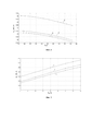
Фиг. 1. Зависимость показателя преломления от температуры Тf. Графикам 1, 2, 3 соответствуют следующие жидкости: дистиллированная вода, водопроводная вода, этиловый спирт.FIG. 1. Dependence of the refractive index on temperature Тf.
Фиг. 2. Зависимость показателя преломления от солености воды Ns для различных температур Тf. Графикам 1, 2, 3 соответствует Тf в К: 283.1, 293.1, 303.2.FIG. 2. Dependence of the refractive index on water salinity Ns for different temperatures Tf.
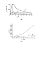
Фиг. 3. Зависимость динамической погрешности проточного рефрактометра от характера изменения расхода q. Графики 1 и 3 соответствуют изменению q скачкообразно в ранее используемой и разработанной нами конструкции рефрактометра. Графики 2 и 4 соответствуют режиму q = const в ранее используемой и разработанной нами конструкции рефрактометра.FIG. 3. Dependence of the dynamic error of the flow-through refractometer on the nature of the change in flow rate q.
Фиг. 4. Зависимость изменения оптической плотности Δd от значения расхода q различных сред при Тf = 293.2 K. График 1, 2, 3 соответствуют: воде; водному раствору гидроксида натрия; водному раствору яблочного сока с растворенным сахаром и мякотью.FIG. 4. Dependence of the change in optical density Δd on the flow rate q of various media at Тf = 293.2
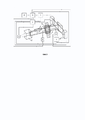
Фиг. 5. Структурная схема разработанной конструкции рефрактометра дифференциального типа.FIG. 5. Block diagram of the developed design of a differential refractometer.
Анализ результатов исследований различных сред с использованием конструкции рефрактометра дифференциального типа позволил разработать формулу для определения погрешности измерения ![]()
![]()
![]()
![]()
![]()
![]()
(b(τcτftp1 + k1τft +τc) ![]()
![]()
(b(τcτftp2 + k2τft +τc) ![]()
![]()
(b(τcτftp3 + k2τft+τc) ![]()
![]()
где p1 = -1/τd; p2,3 = (-(τc - τft) ± ![]()
![]()
τc – постоянная времени замкнутой кюветы, τft – постоянная времени проточной кюветы, L- расстояние от дифференциальной кюветы до фотоприемника, b – температурный градиент показателя преломления текущей жидкости, k1 и k2 – коэффициенты характеризующие размеры проточной и замкнутой кюветы, массу и теплоемкость жидкостей в них находящихся и прочие; Tf – температура проточной жидкости; Tc – температура эталонной жидкости.τ c is the time constant of the closed cell, τ ft is the time constant of the flow cell, L is the distance from the differential cell to the photodetector, b is the temperature gradient of the refractive index of the flowing liquid, k 1 and k 2 are the coefficients characterizing the dimensions of the flow and closed cell, the mass and heat capacity of liquids in them and others; T f is the temperature of the flowing liquid; T c is the temperature of the reference liquid.
Соотношение (2) показывает, что проводить исследования влияния оптической плотности на погрешность измерения ![]()
![]()
![]()
![]()
Поэтому нами для исследования влияния оптической плотности на погрешность измерения ![]()
![]()
![]()
![]()
Наиболее близким по технической реализации являются решения, принятые за прототипы (авторские свидетельства СССР: АС № 640184 - опубликовано: 30.12.1978 и АС № 433857 - опубликовано: 12.04.1973). Изобретение описывает способ измерения показателя преломления ![]()
![]()
В случае размещения замкнутой кюветы внутри проточной для выравнивания температур исследуемой и эталонной жидкости в конструкции дифференциальной кювете Андерсона, возникает ряд дополнительных проблем. Основная из которых связана с образованием застойных зон, особенно при быстрых потоках жидкой среды около замкнутой кюветы. В этих зонах накапливаются примеси, которые потом при попадании в среду (особенно в биологических растворах) могут вызвать необратимые процессы.In the case of placing a closed cell inside the flow cell to equalize the temperatures of the test and reference liquid in the design of the Anderson differential cell, a number of additional problems arise. The main one is associated with the formation of stagnant zones, especially with fast flows of a liquid medium near a closed cell. In these zones, impurities accumulate, which then, when they enter the environment (especially in biological solutions), can cause irreversible processes.
Кроме того, для случая проточной жидкости возникают неопределенность в установлении значения коэффициента пропорциональности KI, который зависит от температуры текущей среды и углов падения лазерного излучения на стенки дифференциальной кюветы Андерсона. В случае измерения показателя преломления неподвижной жидкости (представленные прототипы) можно подобрать эталонную жидкость, чтобы значение Δn было небольшим и контролировать изменение температуры. В текущей жидкости это намного сложнее.In addition, for the case of a flowing liquid, uncertainty arises in establishing the value of the proportionality coefficient K I , which depends on the temperature of the flowing medium and the angles of incidence of laser radiation on the walls of the differential Anderson cuvette. In the case of measuring the refractive index of a stationary liquid (prototypes presented), it is possible to select a reference liquid so that the value of Δn is small and the change in temperature can be monitored. In a flowing fluid, this is much more difficult.
В новой разработанной нами конструкции рефрактометра для реализации метода исследования оптической плотности воздействие этих негативных факторов на результаты измерений несущественно. Его структурная схема, представленная на фиг. 5, состоит из следующих элементов:In the new design of the refractometer developed by us for the implementation of the method of studying the optical density, the influence of these negative factors on the measurement results is insignificant. Its block diagram, shown in Fig. 5, consists of the following elements:
1. Полупроводниковый лазер на гетероструктурах с λ = 632.8 нм, с длиной поперечной пространственной когерентности Ltk = 10 мм, углом расходимости излучения θ ≈ 0.02 мрад для создания когерентного, монохроматического излучения;1. Semiconductor laser based on heterostructures with λ = 632.8 nm, with a transverse spatial coherence length L tk = 10 mm, a radiation divergence angle θ ≈ 0.02 mrad to create coherent, monochromatic radiation;
2. Многофункциональный блок питания полупроводникового лазера и электронных элементов схемы регистрации и обработки информации; 2. Multifunctional power supply unit for semiconductor laser and electronic elements of the information registration and processing circuit;
3. Оптическая система (призменный коллиматор), на выходе которого формируется параллельный пучок заданной формы;3. Optical system (prism collimator), at the output of which a parallel beam of a given shape is formed;
4. Призма Дове - отражательная призма, предназначена для оборачивания изображения при сохранении направления лазерного излучения. В главном сечении призма представляет собой равнобедренную трапецию, боковые стороны которой наклонены к основанию под углом 45°. Изготовлена из кварцевого стекла UVFS.4. Dove prism - a reflective prism designed to wrap the image while maintaining the direction of the laser radiation. In the main section, the prism is an isosceles trapezoid, the sides of which are inclined to the base at an angle of 45 °. Made of UVFS quartz glass.
5. Замкнутая кювета предназначена для размещения эталонной жидкости. Представляет собой цилиндрический трубопровод с пустотой по центральной оси для размещения проточной кюветы;5. The closed cuvette is designed to accommodate the reference liquid. It is a cylindrical tubing with a central void to accommodate the flow cell;
6. Проточная кювета для размещения исследуемой текущей жидкости. Представляет собой цилиндрический трубопровод, который размещается внутри замкнутой кюветы;6. A flow cell for placement of the investigated flowing liquid. It is a cylindrical pipeline that is placed inside a closed cell;
7. Делительная призма предназначена для разделения световых потоков. Изготовлена из стекла ВК7; 7. The dividing prism is designed to separate the light flux. Made of VK7 glass;
8. Фотодиодная линейка для регистрации картины прошедшего через кюветы рассеянного лазерного излучения от границ сред для определения освещенности. Для этого фотодиодная линейка состоит из одиночных сенсоров, которые можно объединить в фотодиодные структуры для регистрации рассеянного лазерного излучения;8. Photodiode ruler for registration of the pattern of the scattered laser radiation passed through the cuvettes from the boundaries of the media to determine the illumination. For this, the photodiode array consists of single sensors that can be combined into photodiode structures for recording scattered laser radiation;
9. Аналого-цифровой преобразователь;9. Analog-to-digital converter;
10. Устройство обработки и управления для обработки сигналов информативного отклонения и определения необходимых операции по подстройки оптической системы на максимум отношения сигнал/шум.10. A processing and control device for processing informative deviation signals and determining the necessary operations to adjust the optical system to the maximum signal-to-noise ratio.
11. Ноутбук;11. Laptop;
12. Датчик температуры для контроля температуры текущей среды в зоне проведения измерений. Контроль температуры необходим, так как значения показателя преломления текущей и эталонной среды зависит от значения данного параметра;12. Temperature sensor for monitoring the temperature of the flowing medium in the measurement area. Temperature control is necessary, since the values of the refractive index of the current and reference medium depend on the value of this parameter;
13. Блок обработки информации датчика температуры предназначен для введения данных о температуре в ноутбук для выбора соответствующих градуировочных таблиц при измерении показателя преломления текущей жидкости. 13. The block for processing information of the temperature sensor is intended for entering temperature data into a laptop to select the appropriate calibration tables when measuring the refractive index of a flowing liquid.
В новой конструкции оптической части рефрактометра (фиг. 5) полупроводниковый лазер 1 с λ = 632.8 нм устанавливается таким образом, чтобы после прохождения оптической систему 3 (призменный коллиматор) его лучей сформировался параллельный пучок заданной формы. Выбор длины волны лазера 1 обусловлен тем, что значения показателей преломления эталонных наборов для поверки рефрактометров измерены на красной линии (λ = 632.8 нм) лазерного излучения гелий-неонового лазера. Кроме того, большинство промышленных проточных рефрактометров работают на этой длине волны.In the new design of the optical part of the refractometer (Fig. 5), a
В конструкции рефрактометра используются измерительные кюветы цилиндрической формы проточная 6 и замкнутая 5, текущая жидкость движется по проточной кювете 6 в направлении перпендикулярном относительно поступающего на её стенку лазерному излучению, температура текущей жидкости в проточной кювете и эталонной жидкости в замкнутой кювете контролируется датчиками температуры 12, информация от них через специальные устройства 13 поступает на устройство обработки информации 10, для регистрации излучения используются две фотодиодные линейки TSL1406RS, состоящие из 512 фоточувствительных сенсоров (компания AMS-TAOS USA), с длиной фоточувствительного слоя 40.16 мм, с фотодиодных линеек 8 сигналы через аналогово-цифровые преобразователи поступают в устройство обработки информации, разработанное на основе микроконтроллера STM32 (ARM Cortex M3 core - STM32F100RBT6B), микроконтроллера информация поступает на ноутбук, который используется для определения значения ![]()
![]()
В разработанной нами новой конструкции рефрактометра кюветы 5 и 6 расположены в вертикальном положении. Такой способ расположения кювет позволяет исключить наличие пустот в проточной кювете при малых расходах жидкости, в отличие от ранее используемых конструкций кювет в дифференциальных рефрактометрах. Такое размещение кювет позволяет полностью исключить образование в них застойных зон и обеспечить более эффективный теплообмен между текущей жидкостью и эталонной по сравнению с ранее используемыми конструкциями рефрактометров. Существенно снижается влияние вклада погрешности от изменения температуры Тf текущей жидкости (особенно при резком изменении Тf) на погрешность измерения ![]()
![]()
![]()
![]()
где Δd = ![]()
![]()
![]()
![]()
В новом методе для измерения показателя преломления ![]()
![]()
β = ΔА = ![]()
![]()
![]()
![]()
где Kar – коэффициент пропорциональности, where K ar - coefficient of proportionality,
![]()
![]()
Нормировка выходного сигналу A с фотодиодной линейки осуществляется по следующему принципу:The standardization of the output signal A from the photodiode bar is carried out according to the following principle:
A = ![]()
![]()
где Аmax – максимальное значение сигнала освещенности с элемента фотодиодной линейки, Аi – амплитуда сигнала с элемента фотодиодной ячейки, i – номер элемента.where A max is the maximum value of the illumination signal from the element of the photodiode array, And i is the amplitude of the signal from the element of the photodiode cell, i is the number of the element.
Коэффициент пропорциональности Kar определяется при предварительной градуировке рефрактометра. Для этого используются две жидкости с известными показателями преломления: дистиллированная вода и этанол (этиловый спирт). Для прозрачных сред значение Kar не изменяется.The proportionality coefficient K ar is determined during the preliminary calibration of the refractometer. For this, two liquids with known refractive indices are used: distilled water and ethanol (ethyl alcohol). For transparent media, the K ar value does not change.
После обработки сигналов нормированные значения их амплитуд A_ar^1,A_ar^2 используются в соотношении (4) для определения значение n_f, далее вычисляется д(Дn), после чего используя соотношение (3) определяется изменение оптической плотности Дd. After processing the signals, the normalized values of their amplitudes A_ar ^ 1, A_ar ^ 2 are used in relation (4) to determine the value of n_f, then d (Dn) is calculated, after which, using relation (3), the change in the optical density Dd is determined.
В конструкции фотодиодной линейки TSL1406RS перед фоточувствительным слоем нет фокусирующих оптических элементов, как в других моделях линеек. Поэтому влияние эффектов, связанных с неоднократным отражением лазерного излучения между фоточувствительным слоем и гранями призмы 7, на отношение сигнал/шум на фоточувствительных сенсорах несущественно.In the design of the TSL1406RS photodiode array, there are no focusing optical elements in front of the photosensitive layer, as in other ruler models. Therefore, the influence of the effects associated with repeated reflection of laser radiation between the photosensitive layer and the faces of the prism 7 on the signal-to-noise ratio on photosensitive sensors is insignificant.
В измерениях показателя преломления с использованием проточных рефрактометрах наиболее неинформативным параметром является температура текущей жидкости Tf. Температура контролируемой и сравнительной жидкости между собой связаны. При изменении Tf изменяется ![]()
![]()
![]()
![]()
![]()
![]()
![]()
![]()
Если среда состоит из нескольких компонент (растворенных друг в друге), например, водный раствор гидроксида натрия, то по причине неодинакового поглощения света по ширине светового потока в слоях текущей жидкости, особенно при их перемешивании, значение Дd незначительно возрастает. Разработанная нами схема компенсации устраняет рассогласования в оптических путях лазерных лучей. Это позволяет проводить измерения показателя преломления с погрешностью 10-4 и меньше. В случае более сложной среды, например, водный раствор сока с сахаром и мякотью (прозрачный) до определенного значения расхода q и температуры текущей среды схема компенсации работает успешно. В дальнейшем влияние изменения значения Дd на погрешность измерения ![]()
![]()
![]()
![]()
Изобретение может быть использовано для проведения фундаментальных научных исследований жидких сред для разработки новых и совершенствования используемых методов измерения показателя преломления, а также для контроля состояния различных текущих сред в пищевой, химической и фармацевтической промышленности, сельском хозяйстве, для определения уровня загрязнения сточных вод от промышленных и сельскохозяйственных предприятий и жилых комплексов.The invention can be used for fundamental scientific research of liquid media for the development of new and improvement of the used methods for measuring the refractive index, as well as for monitoring the state of various flowing media in the food, chemical and pharmaceutical industries, agriculture, for determining the level of wastewater pollution from industrial and agricultural enterprises and residential complexes.
ПримерExample
Для подтверждения возможностей использования новой конструкции рефрактометра на фиг. 1 в качестве примера представлены зависимости изменения показателя преломления текущих жидкостей от температуры.To confirm the possibilities of using the new design of the refractometer, FIG. 1 as an example, the dependences of the change in the refractive index of flowing liquids on temperature are shown.
Полученные результаты совпали в пределах погрешности измерений со значениями показателей преломления, полученными ранее на других конструкциях рефрактометров.The results obtained coincided within the measurement error with the values of refractive indices previously obtained on other designs of refractometers.
На фиг. 2 представлена зависимость показателя преломления ![]()
![]()
Полученные результаты совпали в пределах погрешности измерения с результатами других исследований. Проведенные эксперименты подтвердили работоспособность предложенного метода измерения ![]()
![]()
Температурная компенсация в рефрактометрах осуществляется в режиме пассивного температурного теплообмена между жидкостями в двух кюветах и зависит от конструкции кюветного преобразователя рефрактометра. На фиг. 3 в качестве примера представлены зависимости исследования динамической погрешности измерения ![]()
![]()
Полученный результат показывает, что в разработанной конструкции рефрактометра влияние динамической погрешности на результат измерения ![]()
![]()
![]()
![]()
![]()
![]()
Проведенные нами исследования показали, что в диапазоне температур от 283 до 343 К, если текущая жидкость однородная (без примесей или добавок - вода), то независимо от режима её течения в трубопроводе влияние изменения оптической плотности на погрешность измерения ![]()
![]()
Claims (7)
Priority Applications (1)
| Application Number | Priority Date | Filing Date | Title |
|---|---|---|---|
| RU2020138663A RU2756373C1 (en) | 2020-11-25 | 2020-11-25 | Method for studying optical density of flowing liquid |
Applications Claiming Priority (1)
| Application Number | Priority Date | Filing Date | Title |
|---|---|---|---|
| RU2020138663A RU2756373C1 (en) | 2020-11-25 | 2020-11-25 | Method for studying optical density of flowing liquid |
Publications (1)
| Publication Number | Publication Date |
|---|---|
| RU2756373C1 true RU2756373C1 (en) | 2021-09-29 |
Family
ID=77999948
Family Applications (1)
| Application Number | Title | Priority Date | Filing Date |
|---|---|---|---|
| RU2020138663A RU2756373C1 (en) | 2020-11-25 | 2020-11-25 | Method for studying optical density of flowing liquid |
Country Status (1)
| Country | Link |
|---|---|
| RU (1) | RU2756373C1 (en) |
Cited By (2)
| Publication number | Priority date | Publication date | Assignee | Title |
|---|---|---|---|---|
| CN113959950A (en) * | 2021-10-28 | 2022-01-21 | 绍兴泊盛科技有限公司 | Detection apparatus for detect liquid refracting index based on light stream accuse chip |
| RU2834195C1 (en) * | 2024-09-26 | 2025-02-04 | ФЕДЕРАЛЬНОЕ ГОСУДАРСТВЕННОЕ БЮДЖЕТНОЕ УЧРЕЖДЕНИЕ НАУКИ ИНСТИТУТ ОРГАНИЧЕСКОЙ ХИМИИ им. Н.Д. ЗЕЛИНСКОГО РОССИЙСКОЙ АКАДЕМИИ НАУК (ИОХ РАН) | Method for laser scanning of fluids in hollow prisms |
Citations (5)
| Publication number | Priority date | Publication date | Assignee | Title |
|---|---|---|---|---|
| SU693180A1 (en) * | 1979-07-25 | 1979-10-28 | Предприятие П/Я Г-4126 | Device for measuring characteristics of liquid optical density |
| RU2084873C1 (en) * | 1994-02-22 | 1997-07-20 | Герасимов Сергей Александрович | Meter of optical density of travelling liquid medium |
| EP2609415A1 (en) * | 2010-08-26 | 2013-07-03 | Services Pétroliers Schlumberger | Method for measuring fractions of hydrocarbon fluids using optical spectroscopy |
| RU157015U1 (en) * | 2015-06-01 | 2015-11-20 | Общество с ограниченной ответственностью "Производственно-технологический центр "УралАлмазИнвест" | FLUID OPTICAL DENSITY METER |
| US20180011027A1 (en) * | 2014-02-01 | 2018-01-11 | aquila biolabs GmbH | Method, device, and system for the automated determination of optical densities or of the change in optical densities of reaction mixtures in shaken reactors |
-
2020
- 2020-11-25 RU RU2020138663A patent/RU2756373C1/en active
Patent Citations (5)
| Publication number | Priority date | Publication date | Assignee | Title |
|---|---|---|---|---|
| SU693180A1 (en) * | 1979-07-25 | 1979-10-28 | Предприятие П/Я Г-4126 | Device for measuring characteristics of liquid optical density |
| RU2084873C1 (en) * | 1994-02-22 | 1997-07-20 | Герасимов Сергей Александрович | Meter of optical density of travelling liquid medium |
| EP2609415A1 (en) * | 2010-08-26 | 2013-07-03 | Services Pétroliers Schlumberger | Method for measuring fractions of hydrocarbon fluids using optical spectroscopy |
| US20180011027A1 (en) * | 2014-02-01 | 2018-01-11 | aquila biolabs GmbH | Method, device, and system for the automated determination of optical densities or of the change in optical densities of reaction mixtures in shaken reactors |
| RU157015U1 (en) * | 2015-06-01 | 2015-11-20 | Общество с ограниченной ответственностью "Производственно-технологический центр "УралАлмазИнвест" | FLUID OPTICAL DENSITY METER |
Cited By (3)
| Publication number | Priority date | Publication date | Assignee | Title |
|---|---|---|---|---|
| CN113959950A (en) * | 2021-10-28 | 2022-01-21 | 绍兴泊盛科技有限公司 | Detection apparatus for detect liquid refracting index based on light stream accuse chip |
| CN113959950B (en) * | 2021-10-28 | 2024-04-12 | 绍兴泊盛科技有限公司 | Detection device for detecting liquid refractive index based on optofluidic chip |
| RU2834195C1 (en) * | 2024-09-26 | 2025-02-04 | ФЕДЕРАЛЬНОЕ ГОСУДАРСТВЕННОЕ БЮДЖЕТНОЕ УЧРЕЖДЕНИЕ НАУКИ ИНСТИТУТ ОРГАНИЧЕСКОЙ ХИМИИ им. Н.Д. ЗЕЛИНСКОГО РОССИЙСКОЙ АКАДЕМИИ НАУК (ИОХ РАН) | Method for laser scanning of fluids in hollow prisms |
Similar Documents
| Publication | Publication Date | Title |
|---|---|---|
| Davydov et al. | An optical method of monitoring the state of flowing media with low transparency that contain large inclusions | |
| Nenninger et al. | Reference-compensated biosensing using a dual-channel surface plasmon resonance sensor system based on a planar lightpipe configuration | |
| CN201837582U (en) | Integrated optical ozone yield detection device | |
| CN104296875B (en) | Device and method for measuring polarization degree of light beam | |
| Davydov et al. | Effect of the absorbance of a flowing liquid on the error of the refractive index measured with a differential refractometer | |
| JPH01313736A (en) | Method and apparatus for measuring refractive index n of material | |
| KR100865755B1 (en) | Multichannel Biosensor Using Surface Plasmon Resonance | |
| CN102042971A (en) | Integrated optical ozone production volume detection device, calibration method and measuring method | |
| Grebenikova et al. | Monitoring of flowing media state by refraction phenomenon | |
| RU2756373C1 (en) | Method for studying optical density of flowing liquid | |
| CN105737995A (en) | High-power laser multi-parameter measurement device based on integrating sphere | |
| Grebenikova et al. | The effect of optical density of the flowing liquid on the measurement error of its refractive index | |
| Docchio et al. | A simple and reliable system for measuring the refractive index of liquids using a position-sensitive detector | |
| CN111272683A (en) | A liquid absorption coefficient measuring device and measuring method | |
| ITAN20070019A1 (en) | SPECTROPHOTOMETRIC REFRACTOMETER | |
| Arai et al. | In situ temperature-compensated ultraviolet spectrophotometry to estimate nitrate and chloride concentrations in estuarine seawater with different salinity and composition | |
| KR100922124B1 (en) | Non-invasive online concentration measuring device of photoactive solution | |
| Hanning et al. | A spectroscopic refractometer for temperature-independent refractive index detection | |
| Provodin et al. | Optical method for express control of the state of liquids | |
| Karabegov | Automatic differential prism refractometer for monitoring process liquids | |
| Al-Hafidh et al. | Multireflection polarimetry in microfluidics | |
| CN117347287A (en) | Optical interference structural self-compensating seawater salinity measuring device | |
| RU2730040C1 (en) | Submerged polarimeter for controlling the portion of aromatic hydrocarbons in light oil products | |
| JP3787332B2 (en) | Thermal lens absorption analyzer | |
| Ushenin et al. | Аpplication of temperature sensors for improving the device based on the phenomenon of surface plasmon resonance |