RU2755714C2 - Systems and methods for producing composite part - Google Patents
Systems and methods for producing composite part Download PDFInfo
- Publication number
- RU2755714C2 RU2755714C2 RU2017136732A RU2017136732A RU2755714C2 RU 2755714 C2 RU2755714 C2 RU 2755714C2 RU 2017136732 A RU2017136732 A RU 2017136732A RU 2017136732 A RU2017136732 A RU 2017136732A RU 2755714 C2 RU2755714 C2 RU 2755714C2
- Authority
- RU
- Russia
- Prior art keywords
- layer
- specified
- width
- target
- measured
- Prior art date
Links
Images

Classifications
-
- B—PERFORMING OPERATIONS; TRANSPORTING
- B29—WORKING OF PLASTICS; WORKING OF SUBSTANCES IN A PLASTIC STATE IN GENERAL
- B29C—SHAPING OR JOINING OF PLASTICS; SHAPING OF MATERIAL IN A PLASTIC STATE, NOT OTHERWISE PROVIDED FOR; AFTER-TREATMENT OF THE SHAPED PRODUCTS, e.g. REPAIRING
- B29C43/00—Compression moulding, i.e. applying external pressure to flow the moulding material; Apparatus therefor
- B29C43/02—Compression moulding, i.e. applying external pressure to flow the moulding material; Apparatus therefor of articles of definite length, i.e. discrete articles
- B29C43/10—Isostatic pressing, i.e. using non-rigid pressure-exerting members against rigid parts or dies
-
- B—PERFORMING OPERATIONS; TRANSPORTING
- B29—WORKING OF PLASTICS; WORKING OF SUBSTANCES IN A PLASTIC STATE IN GENERAL
- B29C—SHAPING OR JOINING OF PLASTICS; SHAPING OF MATERIAL IN A PLASTIC STATE, NOT OTHERWISE PROVIDED FOR; AFTER-TREATMENT OF THE SHAPED PRODUCTS, e.g. REPAIRING
- B29C70/00—Shaping composites, i.e. plastics material comprising reinforcements, fillers or preformed parts, e.g. inserts
- B29C70/04—Shaping composites, i.e. plastics material comprising reinforcements, fillers or preformed parts, e.g. inserts comprising reinforcements only, e.g. self-reinforcing plastics
- B29C70/28—Shaping operations therefor
- B29C70/30—Shaping by lay-up, i.e. applying fibres, tape or broadsheet on a mould, former or core; Shaping by spray-up, i.e. spraying of fibres on a mould, former or core
- B29C70/38—Automated lay-up, e.g. using robots, laying filaments according to predetermined patterns
- B29C70/386—Automated tape laying [ATL]
-
- B—PERFORMING OPERATIONS; TRANSPORTING
- B29—WORKING OF PLASTICS; WORKING OF SUBSTANCES IN A PLASTIC STATE IN GENERAL
- B29C—SHAPING OR JOINING OF PLASTICS; SHAPING OF MATERIAL IN A PLASTIC STATE, NOT OTHERWISE PROVIDED FOR; AFTER-TREATMENT OF THE SHAPED PRODUCTS, e.g. REPAIRING
- B29C70/00—Shaping composites, i.e. plastics material comprising reinforcements, fillers or preformed parts, e.g. inserts
- B29C70/04—Shaping composites, i.e. plastics material comprising reinforcements, fillers or preformed parts, e.g. inserts comprising reinforcements only, e.g. self-reinforcing plastics
- B29C70/28—Shaping operations therefor
- B29C70/30—Shaping by lay-up, i.e. applying fibres, tape or broadsheet on a mould, former or core; Shaping by spray-up, i.e. spraying of fibres on a mould, former or core
-
- B—PERFORMING OPERATIONS; TRANSPORTING
- B29—WORKING OF PLASTICS; WORKING OF SUBSTANCES IN A PLASTIC STATE IN GENERAL
- B29C—SHAPING OR JOINING OF PLASTICS; SHAPING OF MATERIAL IN A PLASTIC STATE, NOT OTHERWISE PROVIDED FOR; AFTER-TREATMENT OF THE SHAPED PRODUCTS, e.g. REPAIRING
- B29C70/00—Shaping composites, i.e. plastics material comprising reinforcements, fillers or preformed parts, e.g. inserts
- B29C70/04—Shaping composites, i.e. plastics material comprising reinforcements, fillers or preformed parts, e.g. inserts comprising reinforcements only, e.g. self-reinforcing plastics
- B29C70/28—Shaping operations therefor
- B29C70/54—Component parts, details or accessories; Auxiliary operations, e.g. feeding or storage of prepregs or SMC after impregnation or during ageing
- B29C70/541—Positioning reinforcements in a mould, e.g. using clamping means for the reinforcement
-
- B—PERFORMING OPERATIONS; TRANSPORTING
- B21—MECHANICAL METAL-WORKING WITHOUT ESSENTIALLY REMOVING MATERIAL; PUNCHING METAL
- B21D—WORKING OR PROCESSING OF SHEET METAL OR METAL TUBES, RODS OR PROFILES WITHOUT ESSENTIALLY REMOVING MATERIAL; PUNCHING METAL
- B21D53/00—Making other particular articles
-
- B—PERFORMING OPERATIONS; TRANSPORTING
- B29—WORKING OF PLASTICS; WORKING OF SUBSTANCES IN A PLASTIC STATE IN GENERAL
- B29C—SHAPING OR JOINING OF PLASTICS; SHAPING OF MATERIAL IN A PLASTIC STATE, NOT OTHERWISE PROVIDED FOR; AFTER-TREATMENT OF THE SHAPED PRODUCTS, e.g. REPAIRING
- B29C70/00—Shaping composites, i.e. plastics material comprising reinforcements, fillers or preformed parts, e.g. inserts
- B29C70/04—Shaping composites, i.e. plastics material comprising reinforcements, fillers or preformed parts, e.g. inserts comprising reinforcements only, e.g. self-reinforcing plastics
- B29C70/06—Fibrous reinforcements only
- B29C70/10—Fibrous reinforcements only characterised by the structure of fibrous reinforcements, e.g. hollow fibres
- B29C70/16—Fibrous reinforcements only characterised by the structure of fibrous reinforcements, e.g. hollow fibres using fibres of substantial or continuous length
-
- B—PERFORMING OPERATIONS; TRANSPORTING
- B29—WORKING OF PLASTICS; WORKING OF SUBSTANCES IN A PLASTIC STATE IN GENERAL
- B29C—SHAPING OR JOINING OF PLASTICS; SHAPING OF MATERIAL IN A PLASTIC STATE, NOT OTHERWISE PROVIDED FOR; AFTER-TREATMENT OF THE SHAPED PRODUCTS, e.g. REPAIRING
- B29C70/00—Shaping composites, i.e. plastics material comprising reinforcements, fillers or preformed parts, e.g. inserts
- B29C70/04—Shaping composites, i.e. plastics material comprising reinforcements, fillers or preformed parts, e.g. inserts comprising reinforcements only, e.g. self-reinforcing plastics
- B29C70/28—Shaping operations therefor
- B29C70/40—Shaping or impregnating by compression not applied
- B29C70/42—Shaping or impregnating by compression not applied for producing articles of definite length, i.e. discrete articles
- B29C70/44—Shaping or impregnating by compression not applied for producing articles of definite length, i.e. discrete articles using isostatic pressure, e.g. pressure difference-moulding, vacuum bag-moulding, autoclave-moulding or expanding rubber-moulding
-
- B—PERFORMING OPERATIONS; TRANSPORTING
- B29—WORKING OF PLASTICS; WORKING OF SUBSTANCES IN A PLASTIC STATE IN GENERAL
- B29C—SHAPING OR JOINING OF PLASTICS; SHAPING OF MATERIAL IN A PLASTIC STATE, NOT OTHERWISE PROVIDED FOR; AFTER-TREATMENT OF THE SHAPED PRODUCTS, e.g. REPAIRING
- B29C70/00—Shaping composites, i.e. plastics material comprising reinforcements, fillers or preformed parts, e.g. inserts
- B29C70/04—Shaping composites, i.e. plastics material comprising reinforcements, fillers or preformed parts, e.g. inserts comprising reinforcements only, e.g. self-reinforcing plastics
- B29C70/28—Shaping operations therefor
- B29C70/54—Component parts, details or accessories; Auxiliary operations, e.g. feeding or storage of prepregs or SMC after impregnation or during ageing
- B29C70/545—Perforating, cutting or machining during or after moulding
-
- B—PERFORMING OPERATIONS; TRANSPORTING
- B29—WORKING OF PLASTICS; WORKING OF SUBSTANCES IN A PLASTIC STATE IN GENERAL
- B29C—SHAPING OR JOINING OF PLASTICS; SHAPING OF MATERIAL IN A PLASTIC STATE, NOT OTHERWISE PROVIDED FOR; AFTER-TREATMENT OF THE SHAPED PRODUCTS, e.g. REPAIRING
- B29C70/00—Shaping composites, i.e. plastics material comprising reinforcements, fillers or preformed parts, e.g. inserts
- B29C70/04—Shaping composites, i.e. plastics material comprising reinforcements, fillers or preformed parts, e.g. inserts comprising reinforcements only, e.g. self-reinforcing plastics
- B29C70/28—Shaping operations therefor
- B29C70/54—Component parts, details or accessories; Auxiliary operations, e.g. feeding or storage of prepregs or SMC after impregnation or during ageing
- B29C70/546—Measures for feeding or distributing the matrix material in the reinforcing structure
-
- B—PERFORMING OPERATIONS; TRANSPORTING
- B29—WORKING OF PLASTICS; WORKING OF SUBSTANCES IN A PLASTIC STATE IN GENERAL
- B29C—SHAPING OR JOINING OF PLASTICS; SHAPING OF MATERIAL IN A PLASTIC STATE, NOT OTHERWISE PROVIDED FOR; AFTER-TREATMENT OF THE SHAPED PRODUCTS, e.g. REPAIRING
- B29C2793/00—Shaping techniques involving a cutting or machining operation
- B29C2793/0081—Shaping techniques involving a cutting or machining operation before shaping
-
- B—PERFORMING OPERATIONS; TRANSPORTING
- B29—WORKING OF PLASTICS; WORKING OF SUBSTANCES IN A PLASTIC STATE IN GENERAL
- B29K—INDEXING SCHEME ASSOCIATED WITH SUBCLASSES B29B, B29C OR B29D, RELATING TO MOULDING MATERIALS OR TO MATERIALS FOR MOULDS, REINFORCEMENTS, FILLERS OR PREFORMED PARTS, e.g. INSERTS
- B29K2045/00—Use of polymers of unsaturated cyclic compounds having no unsaturated aliphatic groups in a side-chain, e.g. coumarone-indene resins or derivatives thereof, as moulding material
-
- B—PERFORMING OPERATIONS; TRANSPORTING
- B29—WORKING OF PLASTICS; WORKING OF SUBSTANCES IN A PLASTIC STATE IN GENERAL
- B29K—INDEXING SCHEME ASSOCIATED WITH SUBCLASSES B29B, B29C OR B29D, RELATING TO MOULDING MATERIALS OR TO MATERIALS FOR MOULDS, REINFORCEMENTS, FILLERS OR PREFORMED PARTS, e.g. INSERTS
- B29K2063/00—Use of EP, i.e. epoxy resins or derivatives thereof, as moulding material
-
- B—PERFORMING OPERATIONS; TRANSPORTING
- B29—WORKING OF PLASTICS; WORKING OF SUBSTANCES IN A PLASTIC STATE IN GENERAL
- B29K—INDEXING SCHEME ASSOCIATED WITH SUBCLASSES B29B, B29C OR B29D, RELATING TO MOULDING MATERIALS OR TO MATERIALS FOR MOULDS, REINFORCEMENTS, FILLERS OR PREFORMED PARTS, e.g. INSERTS
- B29K2105/00—Condition, form or state of moulded material or of the material to be shaped
- B29K2105/06—Condition, form or state of moulded material or of the material to be shaped containing reinforcements, fillers or inserts
- B29K2105/08—Condition, form or state of moulded material or of the material to be shaped containing reinforcements, fillers or inserts of continuous length, e.g. cords, rovings, mats, fabrics, strands or yarns
- B29K2105/0872—Prepregs
- B29K2105/089—Prepregs fabric
-
- B—PERFORMING OPERATIONS; TRANSPORTING
- B29—WORKING OF PLASTICS; WORKING OF SUBSTANCES IN A PLASTIC STATE IN GENERAL
- B29K—INDEXING SCHEME ASSOCIATED WITH SUBCLASSES B29B, B29C OR B29D, RELATING TO MOULDING MATERIALS OR TO MATERIALS FOR MOULDS, REINFORCEMENTS, FILLERS OR PREFORMED PARTS, e.g. INSERTS
- B29K2105/00—Condition, form or state of moulded material or of the material to be shaped
- B29K2105/25—Solid
- B29K2105/253—Preform
- B29K2105/256—Sheets, plates, blanks or films
-
- B—PERFORMING OPERATIONS; TRANSPORTING
- B29—WORKING OF PLASTICS; WORKING OF SUBSTANCES IN A PLASTIC STATE IN GENERAL
- B29L—INDEXING SCHEME ASSOCIATED WITH SUBCLASS B29C, RELATING TO PARTICULAR ARTICLES
- B29L2031/00—Other particular articles
- B29L2031/30—Vehicles, e.g. ships or aircraft, or body parts thereof
Abstract
Description
УРОВЕНЬ ТЕХНИКИLEVEL OF TECHNOLOGY
Настоящее изобретение в целом относится к композитным деталям, в частности к системам и способам получения композитной детали.The present invention generally relates to composite parts, in particular to systems and methods for producing a composite part.
Если не указано иное, материалы, приведенные в данном разделе, не являются уровнем техники для пунктов формулы изобретения, при этом не предполагается включение указанных материалов в данный раздел в качестве уровня техники.Unless otherwise indicated, the materials in this section are not prior art to the claims, nor are they intended to be included in this section as prior art.
Благодаря легкости и высокой прочности композитные материалы находят широкое применение при изготовлении деталей во множестве различных областей промышленности. Например, в аэрокосмической промышленности используют композитные детали для создания легких конструктивных компонентов воздушного летательного аппарата и космического летательного аппарата, таких как, например, несущие конструкции фюзеляжа, стрингеры, крылья, горизонтальные стабилизаторы и/или вертикальные стабилизаторы. Один из подходов получения композитной детали включает резку множества слоев композитного материала, размещение слоев на каркасе, имеющем требуемую форму, и последующую термообработку слоев, которым придана требуемая форма.Due to their lightness and high strength, composite materials are widely used in the manufacture of parts in many different industries. For example, the aerospace industry uses composite parts to create lightweight aircraft and spacecraft structural components such as, for example, fuselage struts, stringers, wings, horizontal stabilizers, and / or vertical stabilizers. One approach to making a composite part involves cutting multiple layers of composite material, placing the layers on a frame having the desired shape, and then heat treating the layers to the desired shape.
РАСКРЫТИЕ СУЩНОСТИ ИЗОБРЕТЕНИЯDISCLOSURE OF THE INVENTION
Предложены способ и система для получения композитной детали. В одном из примеров способ получения композитной детали включает резку, по одному слою за раз в заданной последовательности на основании спецификации детали, множества слоев материала. В спецификации детали указаны параметры процесса изготовления для получения композитной детали. Способ также включает размещение, по одному слою за раз на основании спецификации детали, множества слоев с получением стопы в области измерения наслаивающего устройства. Для каждого слоя, после его размещения и перед резкой следующего слоя в последовательности, способ включаетA method and a system for producing a composite part are proposed. In one example, a method for producing a composite part includes cutting, one layer at a time in a predetermined sequence based on the part specification, a plurality of layers of material. The part specification specifies the manufacturing process parameters for the composite part. The method also includes placing, one layer at a time based on part specification, multiple layers to form a stack in the measurement area of the layering device. For each layer, after placing it and before cutting the next layer in sequence, the method includes
(i) сканирование слоя по длине для определения изображения слоя,(i) scanning the layer lengthwise to determine the image of the layer,
(ii) определение, на основании указанного изображения, по меньшей двух краев слоя,(ii) determining, based on said image, at least two edges of the layer,
(iii) определение, на основании указанных по меньшей двух краев, измеренной ширины во множестве мест по длине слоя,(iii) determining, based on the specified at least two edges, the measured width at multiple locations along the length of the layer,
(iv) сравнение ширины слоя в каждом месте, с целевой шириной в месте,(iv) comparing the width of the layer at each location, with the target width at the location,
(v) принятие решения, на основании произведенного сравнения, следует ли скорректировать процесс изготовления, и(v) deciding, based on the comparison made, whether the manufacturing process should be adjusted, and
(vi) если указанным решением является проведение корректировки процесса изготовления, осуществление последующей корректировки процесса изготовления на основании произведенного сравнения измеренной ширины с целевой шириной в каждом месте.(vi) if the specified solution is to make an adjustment to the manufacturing process, to implement a subsequent adjustment to the manufacturing process based on the comparison of the measured width with the target width at each location.
Параметры, указанные в спецификации детали, содержат целевую ширину в каждом месте по длине слоя. Кроме того, по меньшей мере для одного слоя принимают решение скорректировать процесс изготовления.The parameters specified in the BOM contain the target width at each location along the length of the layer. In addition, for at least one layer, a decision is made to adjust the manufacturing process.
Еще в одном примере система для получения композитной детали содержит режущее устройство для резки множества слоев материала, по одному слою за раз, область измерения для приема указанного множества слоев, по одному слою за раз с получением стопы и измерительное устройство для сканирования области измерения. Система также содержит контроллер, выполненный с возможностью побуждать режущее устройство резать, на основании спецификации детали, множество слоев в последовательности по одному слою за раз. В спецификации детали указаны параметры процесса изготовления для получения композитной детали. Для каждого слоя, после приема слоя в области измерения и перед резкой режущим устройством следующего слоя в последовательности, контроллер дополнительно выполнен с возможностью:In yet another example, a system for producing a composite part comprises a cutting device for cutting multiple layers of material, one layer at a time, a measurement region for receiving said plurality of layers, one layer at a time to form a stack, and a measuring device for scanning the measurement region. The system also includes a controller configured to cause the cutter to cut, based on the part specification, multiple layers in sequence, one layer at a time. The part specification specifies the manufacturing process parameters for the composite part. For each layer, after receiving the layer in the measurement area and before cutting the next layer in sequence by the cutting device, the controller is further configured to:
(i) побуждать измерительное устройство сканировать слой по длине для определения изображения слоя,(i) cause the measuring device to scan the layer lengthwise to determine the image of the layer,
(ii) определять, на основании изображения, по меньшей мере два края слоя,(ii) determine, based on the image, at least two edges of the layer,
(iii) определять, на основании по меньшей двух краев, измеренной ширины во множестве мест по длине слоя,(iii) determine, based on at least two edges, the measured width at multiple locations along the length of the layer,
(iv) сравнивать измеренную ширину слоя в каждом месте с целевой шириной в месте,(iv) compare the measured layer width at each location with the target width at the location,
(v) принимать решение, на основании произведенного сравнения, следует ли скорректировать процесс изготовления, и(v) decide, based on the comparison made, whether the manufacturing process should be adjusted, and
(vi) если указанным решением является проведение корректировки процесса изготовления, осуществлять последующую корректировку, на основании произведенного сравнения, по меньшей мере одного параметра из спецификации детали для резки следующего слоя в последовательности.(vi) if the specified solution is to adjust the manufacturing process, make subsequent adjustments, based on the comparison made, at least one parameter from the part specification for cutting the next layer in the sequence.
Параметры, указанные в спецификации детали, содержат целевую ширину в каждом месте по длине слоя. По меньшей мере для одного слоя принимают решение скорректировать процесс изготовления.The parameters specified in the BOM contain the target width at each location along the length of the layer. For at least one layer, a decision is made to adjust the manufacturing process.
Еще в одном примере предложен некратковременный компьютерочитаемый носитель данных, содержащий хранящиеся на нем программные инструкции, которые при их исполнении контроллером, побуждают систему изготовления композитных деталей выполнять ряд действий. Система изготовления композитных деталей содержит режущее устройство для резки множества слоев материала, область измерения для приема множества слоев с получением стопы и измерительное устройство для сканирования области измерения. Ряд действий включает резку режущим устройством, на основании спецификации детали, множества слоев в последовательности по одному слою за раз. В спецификации детали указаны параметры процесса изготовления для получения композитной детали. Ряд действий также включает размещение, на основании спецификации детали, множества слоев по одному слою за раз с получением стопы в области измерения. Для каждого слоя, после размещения слоя и перед резкой следующего слоя в последовательности, ряд действий дополнительно включает:In yet another example, a non-transitory computer-readable storage medium is provided containing program instructions stored thereon that, when executed by a controller, cause a composite fabrication system to perform a series of actions. The system for manufacturing composite parts includes a cutting device for cutting multiple layers of material, a measurement area for receiving multiple layers to form a stack, and a measurement device for scanning the measurement area. A number of actions involve cutting with a cutter, based on a part specification, multiple layers in sequence, one layer at a time. The part specification specifies the manufacturing process parameters for the composite part. A number of actions also include placing, based on the BOM, multiple layers, one layer at a time, to obtain a foot in the measurement area. For each layer, after placing the layer and before cutting the next layer in the sequence, a series of actions additionally includes:
(i) сканирование, посредством измерительного устройства, слоя по длине для определения изображения слоя,(i) scanning, by means of a measuring device, a layer along its length to determine an image of the layer,
(ii) определение, на основании изображения, по меньшей двух краев слоя,(ii) determining, based on the image, at least two edges of the layer,
(iii) определение, на основании по меньшей двух краев, измеренной ширины во множестве мест по длине слоя,(iii) determining, based on at least two edges, a measured width at multiple locations along the length of the layer,
(iv) сравнение измеренной ширины слоя в каждом месте с целевой шириной в месте,(iv) comparing the measured layer width at each location with the target width at the location,
(v) принятие решения, на основании произведенного сравнения, следует ли скорректировать процесс изготовления, а(v) deciding, based on the comparison made, whether the manufacturing process should be adjusted, and
(vi) если указанным решением является проведение корректировки процесса изготовления, осуществление последующей корректировки, на основании произведенного сравнения, по меньшей мере одного параметра из спецификации детали для резки следующего слоя в последовательности.(vi) if the specified solution is to make adjustments to the manufacturing process, making subsequent adjustments, based on the comparison made, of at least one parameter from the part specification for cutting the next layer in the sequence.
Параметры, указанные в спецификации детали, содержат целевую ширину в каждом месте по длине слоя. По меньшей мере для одного слоя принимают решение скорректировать процесс изготовления.The parameters specified in the BOM contain the target width at each location along the length of the layer. For at least one layer, a decision is made to adjust the manufacturing process.
Эти и другие аспекты, преимущества и альтернативы будут очевидны специалистам в данной области техники после прочтения приведенного далее подробного описания со ссылкой, при необходимости, на прилагаемые чертежи. Кроме того, следует понимать, что описание, приведенное в разделе «Раскрытие сущности изобретения» и где-либо еще в данном документе, иллюстрирует заявленный объект в качестве примера, а не в качестве ограничения.These and other aspects, advantages and alternatives will become apparent to those skilled in the art upon reading the following detailed description, with reference, as appropriate, to the accompanying drawings. In addition, it should be understood that the description provided in the "Disclosure of the invention" section and elsewhere in this document, illustrates the claimed subject matter by way of example and not limitation.
КРАТКОЕ ОПИСАНИЕ ЧЕРТЕЖЕЙBRIEF DESCRIPTION OF DRAWINGS
Новые признаки, считаемые характеристикой иллюстративных примеров, заданы в прилагаемой формуле изобретения. Однако иллюстративные примеры, а также предпочтительный режим использования, дополнительные задачи и их описания будут наилучшим образом понятны по ссылке на приведенное далее подробное описание иллюстративного примера настоящего изобретения при прочтении вместе с прилагаемыми чертежами.New features considered to be characteristic of the illustrative examples are set forth in the appended claims. However, the illustrative examples, as well as the preferred mode of use, additional objectives and descriptions thereof, will be best understood by reference to the following detailed description of an illustrative example of the present invention when read in conjunction with the accompanying drawings.
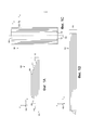
На фиг. 1А показан вид сбоку композитной детали согласно одному из примеров.FIG. 1A is a side view of a composite part according to one example.
На фиг. 1В показан еще один вид сбоку композитной детали, показанной на фиг. 1А.FIG. 1B is another side view of the composite part shown in FIG. 1A.
На фиг. 1С показан вид сверху композитной детали, показанной на фиг. 1А.FIG. 1C is a top view of the composite part shown in FIG. 1A.
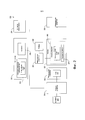
На фиг. 2 показана упрощенная структурная схема системы для получения композитной детали согласно одному из примеров.FIG. 2 is a simplified block diagram of a system for producing a composite part according to one example.
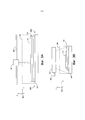
На фиг. 3А показан вид сбоку измерительного устройства для сканирования области измерения наслаивающего устройства согласно одному из примеров.FIG. 3A is a side view of a measurement device for scanning a measurement area of a layering device according to one example.
На фиг. 3В показан еще один вид сбоку измерительного устройства для сканирования области измерения наслаивающего устройства, показанного на фиг. 3А.FIG. 3B is another side view of the measuring device for scanning the measurement area of the layering device shown in FIG. 3A.
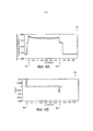
На фиг. 4А показан график, иллюстрирующий измеренную высоту по ширине слоя согласно одному из примеров.FIG. 4A is a graph illustrating measured height versus layer width according to one example.
На фиг. 4В показан график наклона кривой, показанной на фиг. 4А.FIG. 4B is a graph of the slope of the curve shown in FIG. 4A.
На фиг. 5А показан график целевой ширины по длине слоя согласно одному из примеров.FIG. 5A is a plot of target width over layer length according to one example.
На фиг. 5В показана увеличенная часть графика, показанного на фиг. 5А.FIG. 5B is an enlarged portion of the graph of FIG. 5A.
На фиг. 6 показана блок-схема примера процесса получения композитной детали согласно одному из примеров.FIG. 6 is a flowchart of an example of a process for producing a composite part according to one example.
На фиг. 7 показана блок-схема примера процесса получения композитной детали согласно одному из примеров.FIG. 7 is a flowchart of an example of a process for producing a composite part according to one example.
На фиг. 8 показана блок-схема примера процесса получения композитной детали согласно одному из примеров.FIG. 8 is a flow diagram of an example of a process for producing a composite part according to one example.
На фиг. 9 показана блок-схема примера процесса получения композитной детали согласно одному из примеров.FIG. 9 is a flow chart of an example of a process for producing a composite part according to one example.
На фиг. 10 показана блок-схема примера процесса получения композитной детали согласно одному из примеров.FIG. 10 is a flow diagram of an example of a process for producing a composite part according to one example.
На фиг. 11 показана блок-схема примера процесса получения композитной детали согласно одному из примеров.FIG. 11 is a flowchart of an example of a process for producing a composite part according to one example.
На фиг. 12 показана блок-схема примера процесса получения композитной детали согласно одному из примеров.FIG. 12 is a flow diagram of an example of a process for producing a composite part according to one example.
На фиг. 13 показана блок-схема примера процесса получения композитной детали согласно одному из примеров.FIG. 13 is a flowchart of an example of a process for producing a composite part according to one example.
На фиг. 14 показана блок-схема примера процесса получения композитной детали согласно одному из примеров.FIG. 14 is a flowchart of an example of a process for producing a composite part according to one example.
На фиг. 15 показана блок-схема примера процесса получения композитной детали согласно одному из примеров.FIG. 15 is a flowchart of an example of a process for producing a composite part according to one example.
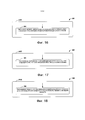
На фиг. 16 показана блок-схема примера процесса получения композитной детали согласно одному из примеров.FIG. 16 is a flowchart of an example of a process for producing a composite part according to one example.
На фиг. 17 показана блок-схема примера процесса получения композитной детали согласно одному из примеров.FIG. 17 is a flowchart of an example of a process for producing a composite part according to one example.
На фиг. 18 показана блок-схема примера процесса получения композитной детали согласно одному из примеров.FIG. 18 is a flow chart of an example of a process for producing a composite part according to one example.
ОСУЩЕСТВЛЕНИЕ ИЗОБРЕТЕНИЯCARRYING OUT THE INVENTION
I. ОбзорI. Overview
Системы и способы согласно настоящему изобретению обеспечивают производственные системы и способы для получения композитной детали. В целом, композитная деталь может быть получена путем резки множества слоев неотвержденного композитного материала, размещения слоев друг на друга с получением стопы и отверждения стопы. Работой системы можно управлять на основании спецификации детали, в которой указаны параметры процесса изготовления. Например, в спецификации детали могут быть указаны параметры, которые обеспечивают заданное количество отрезаемых слоев и целевые размеры каждого слоя. С использованием этих параметров режущее устройство может резать каждый слой с обеспечением необходимых формы и размера. В качестве еще одного примера в спецификации детали могут быть указаны параметры, обеспечивающие заданную последовательность при отрезании слоев и размещении слоев на стопе, и/или параметры, обеспечивающие положение слоев относительно друг друга в стопе. Таким образом, с использованием спецификации детали система может осуществлять процесс изготовления для получения композитной детали в соответствии с необходимым проектом, обеспеченным с помощью спецификации детали.The systems and methods of the present invention provide manufacturing systems and methods for making a composite part. In general, a composite part can be obtained by cutting multiple layers of uncured composite material, stacking the layers on top of each other to form a stack, and curing the foot. The operation of the system can be controlled based on the specification of the part, which specifies the parameters of the manufacturing process. For example, a BOM of a part can specify parameters that provide a specified number of cut layers and target dimensions for each layer. Using these parameters, the cutter can cut each layer to the desired shape and size. As another example, the specification of a part can specify parameters that provide a predetermined sequence when cutting layers and placing layers on the stack, and / or parameters that ensure the position of layers relative to each other in the stack. Thus, using the BOM, the system can carry out the fabrication process to obtain the composite part according to the required design provided by the BOM.
Во время процесса изготовления один или более из слоев могут и не быть изготовлены точно так, как это указано в спецификации детали. Например, процессы для резки и/или размещения слоев могут иметь характерную статистическую вариабельность, которая вызывает изготовление композитной детали с одной или более вариациями и/или ошибками по отношению к спецификации детали. В зависимости от конечного использования композитной детали и/или области промышленности могут являться приемлемыми относительно небольшие отклонения, принимая во внимание, что относительно большие отклонения могут привести к отбраковке композитной детали.During the manufacturing process, one or more of the layers may not be manufactured exactly as specified in the part specification. For example, processes for cutting and / or placing layers may have inherent statistical variability that causes the composite part to be manufactured with one or more variations and / or errors with respect to the part specification. Depending on the end use of the composite part and / or industry, relatively small deviations may be acceptable, whereas relatively large deviations can lead to rejection of the composite part.
В аэрокосмической промышленности, например, требования гарантии качества могут относиться к геометрическим характеристикам композитной детали. В некоторых примерах инспектор может выборочно проверить отдельный слой (например, с использованием штангенциркулей) в нескольких местах для оценки, имеют ли геометрические характеристики слоя отклонение от спецификации детали на величину, превышающую разрешенный технический допуск. Пока инспектор оценивает слой, процесс изготовления может быть остановлен, что привносит относительно длительные задержки в процесс изготовления. Если инспектор определяет, что геометрические характеристики слоя не удовлетворяют разрешенному техническому допуску (то есть, инспектор выявляет состояние выхода за пределы допуска), вся композитная деталь может быть отбракована и утилизирована.In the aerospace industry, for example, quality assurance requirements may relate to the geometric characteristics of a composite part. In some examples, an inspector may selectively inspect an individual layer (for example, using calipers) at multiple locations to assess if the geometry of the layer deviates from part specification by more than the allowed technical tolerance. While the inspector is evaluating the layer, the manufacturing process can be stopped, which introduces relatively long delays in the manufacturing process. If the inspector determines that the geometry of the layer does not meet the permitted technical tolerance (that is, the inspector detects an out-of-tolerance condition), the entire composite part can be discarded and disposed of.
Кроме того, инспектор может осуществить окончательную проверку композитной детали после завершения процесса изготовления. Например, инспектор может оценить окончательный объем композитной детали и определить, находится ли этот окончательный объем в пределах разрешенных технических допусков из спецификации детали. В некоторых примерах инспектор может и не выявить состояния выхода за пределы допуска во время обследования отдельных слоев, однако инспектор может выявить состояние выхода за пределы допуска готовой композитной детали. Это может возникнуть в случае, когда небольшие отклонения в отдельных слоях накапливаются таким образом, что в совокупности вызывают нахождение окончательной части за пределами допуска. В качестве альтернативы, поскольку инспектор может только выборочно проверить отдельные слои в нескольких местах, этот инспектор может упустить состояние выхода за пределы допуска одного или более слоев.In addition, the inspector can carry out the final inspection of the composite part after the completion of the manufacturing process. For example, an inspector can evaluate the final volume of a composite part and determine if that final volume is within the permitted technical tolerances of the part's BOM. In some examples, the inspector may not detect an out-of-tolerance condition while examining individual layers, but an inspector may detect an out-of-tolerance condition on the finished composite part. This can occur when small deviations in individual layers accumulate in such a way that they collectively cause the final portion to be out of tolerance. Alternatively, because an inspector can only selectively inspect individual layers at multiple locations, that inspector may miss the out-of-tolerance state of one or more layers.
Таким образом, существующие системы и способы получения композитной детали подвержены задержкам и/или пустой трате материалов по причине процессов обследования, состояниям выхода за пределы допуска и/или отбраковке полученных композитных деталей. Системы и способы получения композитной детали, предложенные в настоящем изобретении, могут эффективно помочь по меньшей мере частично устранить эти недостатки существующих систем и способов. В частности, системы и способы согласно настоящему изобретению могут уменьшить (или исключить) задержки и потери путем оценки слоев на послойной основе с обеспечением идентификации состояний выхода за пределы допуска во время процесса изготовления и, в случае идентификации состояния выхода за пределы допуска, могут динамически скорректировать один или более последующих этапов в процессе изготовления по меньшей мере для частичного устранения состояния выхода за пределы допуска.Thus, existing systems and methods for producing a composite part are subject to delays and / or wasted materials due to inspection processes, out-of-tolerance conditions, and / or rejection of the resulting composite parts. The systems and methods for producing a composite part provided by the present invention can effectively help at least partially overcome these disadvantages of existing systems and methods. In particular, the systems and methods of the present invention can reduce (or eliminate) delays and losses by evaluating layers on a layer-by-layer basis, ensuring out-of-tolerance conditions are identified during the manufacturing process and, if out-of-tolerance conditions are identified, can dynamically adjust one or more subsequent steps in the manufacturing process to at least partially eliminate the out-of-tolerance condition.
В рамках приведенных примеров после резки каждого слоя измерительное устройство может осуществлять сканирование слоя по длине для определения изображения слоя. Контроллер может определить края слоя на основании определенного изображения и размеры слоя на основании определенных краев. Определенные размеры могут содержать, например, измеренную ширину в многочисленных местах по длине слоя, центровую линию по длине слоя, измеренную площадь поверхности слоя и/или измеренный объем слоя. Для слоя контроллер может сравнивать определенные размеры с соответствующими целевыми размерами, которые обеспечены посредством спецификации детали. Если определено, на основании произведенного сравнения, что существует состояние выхода за пределы допуска (или вероятно будет существовать во время последующих этапов в процессе), то в дальнейшем корректируют процесс изготовления.In the examples given, after each layer has been cut, the measuring device can scan the layer lengthwise to determine the image of the layer. The controller can determine the edges of the layer based on the specific image and the dimensions of the layer based on the defined edges. Specific dimensions can include, for example, measured width at multiple locations along the length of the layer, a centerline along the length of the layer, measured surface area of the layer, and / or measured volume of the layer. For the layer, the controller can compare the defined dimensions with the corresponding target dimensions that are provided through the part BOM. If it is determined, based on the comparison made, that there is an out-of-tolerance condition (or likely to exist during subsequent steps in the process), then the manufacturing process is further adjusted.
В одном из примеров корректировка процесса изготовления включает корректировку одного или более параметров в спецификации детали, которые используют для резки последующего слоя. Например, если определено, что измеренная ширина слоя является слишком узкой, процесс изготовления может быть скорректирован для резки последующего слоя с увеличенной шириной. Аналогичным образом, если определено, что измеренная ширина слоя является слишком широкой, процесс изготовления может быть скорректирован для резки последующего слоя с уменьшенной шириной. В дополнительных или альтернативных примерах корректировка процесса изготовления включает добавление дополнительного материала к слою в стопе, повторное размещение слоя на стопе и/или удаление и резку заменяющего слоя. В рамках приведенных примеров система может эффективно реализовывать эти динамические корректировки в отношении процесса изготовления для реагирования на состояния выхода за пределы допуска без задержек, что улучшает эффективность технологического процесса.In one example, adjusting the manufacturing process includes adjusting one or more parameters in the part list that is used to cut the subsequent layer. For example, if it is determined that the measured layer width is too narrow, the manufacturing process can be adjusted to cut a subsequent layer with an increased width. Likewise, if it is determined that the measured layer width is too wide, the manufacturing process can be adjusted to cut a subsequent layer with a reduced width. In additional or alternative examples, adjusting the manufacturing process includes adding additional material to the layer in the stack, re-placing the layer on the stack, and / or removing and cutting the replacement layer. Within the given examples, the system can efficiently implement these dynamic adjustments to the manufacturing process to respond to out-of-tolerance conditions without delay, which improves process efficiency.
II. Примеры композитных деталейII. Examples of composite parts
На фиг. 1А-1С показана композитная деталь 100 согласно одному из примеров. В частности, на фиг. 1А показан вид сверху одной из сторон композитной детали 100 в плоскости X-Z системы 102 координат, на фиг. 1В показан вид сверху одной из сторон композитной детали 100 в плоскости Y-Z системы 102 координат, а на фиг. 1С показан вид сверху композитной детали в плоскости X-Y системы 102 координат. Для более ясной иллюстрации аспектов композитной детали, фиг. 1А-1С не представлены в масштабе относительно друг друга.FIG. 1A-1C show a
Как показано на фиг. 1А-1С, композитная деталь 100 содержит множество слоев 110 композитного материала, расположенных в стопе 112. Одним из примеров композитного материала, который может быть использован, является легкий материал, такой как неотверждаемая армирующая лента с пропиткой или ткань (то есть «препрег»). Лента или ткань может содержать множество волокон, таких как графитовые волокна, которые реализованы в матричном материале, таком как полимер, например смола или фенопласт. Лента или ткань может быть однонаправленной или плетеной в зависимости от, например, необходимой степени усиления. Слои 110 могут иметь любой размер, подходящий для обеспечения различных степеней усиления, а композитная деталь 100 может содержать любое количество слоев ленты или ткани из препрега.As shown in FIG. 1A-1C,
Слои 110 укладывают друг на друга и выравнивают с обеспечением заданного размера и/или заданной ориентации. Количество слоев 110, которые необходимо уложить в стопу, может зависеть от конечных геометрических размеров конструкции композитной детали 100, так что композитная деталь 100 может быть составлена таким образом, что она имеет необходимую толщину при заданной ориентации. Как показано на фиг. 1С, слои 110 в показанном примере расположены в стопе 112 таким образом, что эти слои 110 выровнены относительно общей центровой линии 114, которая проходит по длине слоев 110 в средней точке между двумя краями 116 слоев 110. В некоторых примерах выравнивание слоев 110 вокруг общей центровой линии 114 может эффективно облегчать достижение конкретных геометрических параметров конструкции детали из спецификации детали.The
Как показано на фиг. 1А-1С, каждый слой 110 имеет длину, проходящую в направлении, параллельном Y-оси системы 102 координат, ширину, проходящую в направлении, параллельном Х-оси системы 102 координат, и высоту, проходящую в направлении, параллельном Z-оси системы 102 координат. В показанном примере слои 110 обычно имеют одни и те же значения длины и значения высоты, но имеют разные значения ширины. Кроме того, в показанном примере слои 110 в целом выполнены прямоугольными, при этом ширина слоя 110 уменьшается от самого нижнего слоя в стопе 112 до самого верхнего слоя в стопе 112. В дополнительных или альтернативных примерах слои 110 могут иметь формы, размеры и/или ориентации, отличные от тех, которые показаны на фиг. 1А-1С.As shown in FIG. 1A-1C, each
III. Пример системIII. Example systems
На фиг. 2 показана упрощенная схема системы 200 для получения композитной детали 100 согласно одному из примеров. Как показано на фиг. 2, система 200 может содержать контроллер 217, режущее устройство 218, размещающее устройство 220, укладчик 222, измерительное устройство 224, привод 226, отверждающее устройство 228 и устройство 230 ввода-вывода. Эти компоненты системы 200 могут быть соединены любым способом, в том числе с помощью проводных или беспроводных соединений. Кроме того, в некоторых примерах компоненты системы 200, показанные в виде одиночного объекта, могут быть распределены среди множества физических объектов, а компоненты, показанные в виде многочисленных объектов, могут быть реализованы в виде одиночного физического объекта.FIG. 2 shows a simplified diagram of a
Контроллер 217 может быть реализован с использованием аппаратных средств, программного обеспечения и/или прошивки. Например, контроллер 217 может содержать один или более процессоров 232 и некратковременный компьютерочитаемый носитель 234 данных (например, энергозависимую и/или энергонезависимую память), который хранит инструкции на машинном языке или иные исполняемые инструкции. Инструкции при их исполнении одним или более процессорами побуждают контроллер 217 выполнять различные операции системы 200, описанной в данном документе.
Как показано на фиг. 2, компьютерочитаемый носитель 234 данных хранит спецификацию 236 детали, в которой указаны множество параметров, относящиеся к процессу изготовления для получения композитной детали 100. В качестве примеров спецификация 236 детали может содержать параметры, касающиеся количества слоев 110 композитной детали 100, один или более целевых размеров каждого слоя 110, последовательность резки слоев 110, последовательность размещения слоев 110 на наслаивающем устройстве 222, целевое местоположение каждого слоя 110 в стопе 112 и/или целевой объем стопы 112 на каждом этапе в процессе изготовления. В одной из реализаций целевые размеры каждого слоя 110 содержат целевую ширину в каждом месте из множества мест по длине слоя 110. В качестве дополнительных или альтернативных примеров параметры могут относится к технологическим допускам, которые могут обеспечивать пороговые значения или величины для определения, следует ли скорректировать процесс изготовления, как описано более подробно ниже. Параметры из спецификации 236 детали могут дополнительно содержать компьютерочитаемые инструкции, которые, при их исполнении контроллером 217, обеспечивают управление работой компонентов системы 200 для осуществления процесса изготовления для получения композитной детали 100.As shown in FIG. 2, the computer-
В одном из примеров контроллер 217 может определить спецификацию 236 детали на основании, по меньшей мере частично, реализуемого с помощью компьютера программного обеспечения, которое принимает входные данные, связанные с конструкцией композитной детали 100, и генерирует параметры системы 200 из этих входных данных. Например, программное обеспечение может содержать программные средства автоматизированного проектирования (CAD) для указания конструктивных аспектов композитной детали 100, в том числе конструктивных аспектов, относящихся к одному или более из вышеописанных примеров параметров.In one example,
Режущее устройство 218 выполнено с возможностью резки материала 238, по одному слою за раз, на множество слоев 110. В одном из примеров режущее устройство 218 содержит режущее приспособление, которое может совершать перемещение вдоль одной или более машинных осей с тем, чтобы следовать запрограммированной траектории резки, основанной на спецификации 236 детали. Например, один или более параметров из спецификации 236 детали могут обеспечить координаты, соответствующие целевым краям слоя 110, а режущее приспособление может совершать перемещение вдоль траектории резки, содержащей координаты. Координаты для направления режущего устройства 218 могут быть основаны на параметрах из спецификации 236 детали, в которой указана целевая ширина в каждом месте из множества мест по длине каждого слоя 110. В силу этого режущее устройство 218 выполняет резку слоя 110 до целевых размеров, указанных посредством параметров из спецификации 236 детали для слоя 110.
В одном из примеров режущее устройство 218 может содержать машину с числовым программным управлением (CNC) с одним или более ультразвуковыми режущими инструментами, каждый из которых имеет режущий нож, приводимый в действие ультразвуковым преобразователем. Ультразвуковой режущий инструмент или ультразвуковые режущие инструменты могут быть соединены с резцовой головкой, которая может совершать перемещение вдоль одной или более машинных осей с тем, чтобы следовать запрограммированной траектории резки, основанной на спецификации 236 детали. В качестве дополнительных или альтернативных примеров для резки каждого слоя 110 от материала 238 режущее устройство 218 может содержать одну или более из ленточных пил, фрезы, ножовочных пил, насадки шлифовальной машинки и/или срезающих колес.In one example, the
Укладчик 222 имеет поверхность 240 укладки, на которой располагают слои 110 с получением стопы 112. Укладчик 222 также имеет область 242 измерения, которая содержит объем свободного пространства, проходящего от поверхности 240 укладки до измерительного устройства 224 (как показано на фиг. 3А-3В и описано более подробно ниже). В силу этого укладчик 222 принимает, по одному слою за раз, слои 110 в области 242 измерения, когда эти слои 110 размещают с получением стопы 112 на поверхности 240 укладки.
Как показано на фиг. 2, система 200 может содержать размещающее устройство 220, которое облегчает размещение слоев 110 в области 242 измерения укладчика 222. Например, в реализации, в которой режущее устройство 218 находится в первом состоянии, а укладчик 222 находится во втором состоянии, позиционирующее устройство 220 может содержать транспортировочное устройство для перемещения, по одному слою за раз, слоев 110 с режущего устройства 218 на укладчик 222. Например, размещающее устройство 220 может содержать одну или более бобин для сдвигания каждого слоя 110 с режущего устройства 218 на укладчик 222.As shown in FIG. 2,
В качестве еще одного примера позиционирующее устройство 220 может содержать одно или более робототехнических устройств, содержащих рабочие органы, которые могут физически взаимодействовать с каждым слоем 110 с обеспечением размещения этих слоев 110 относительно друг друга в области 242 измерения. Робототехническими устройствами можно управлять на основании спецификации 236 детали. Например, параметры из спецификации 236 детали могут определять координаты на наслаивающем устройстве 222 для целевого местоположения каждого слоя 110, а робототехническое устройство или робототехнические устройства может или могут перемещать слой 110 в целевое место.As yet another example,
В качестве еще одного примера позиционирующее устройство 220 может содержать физическую модель и/или модель из спроецированного света для облегчения ручной укладки слоев 110 на поверхность 240 укладки. Работа модели или моделей также может быть основана на спецификации 236 детали. Например, модель из спроецированного света может проецировать модель освещения, что указывает на местоположение каждого слоя 110 на поверхности 240 укладки на основании координат для модели освещения, обеспеченной посредством параметров из спецификации 236 детали.As another example,
В качестве дополнительного или альтернативного примера позиционирующее устройство 220 может быть объединено с режущим устройством 218. Например, в некоторых примерах режущее устройство 218 может резать каждый слой 110 и может размещать слой 110 на наслаивающем устройстве 222 по существу одновременно. В одной из реализаций материал 238 размещают на стопе 112, а режущее устройство 218 в дальнейшем выполняют резку следующего слоя 110 от материала на месте на стопе 112, при этом удаляют любой лишний материал 238. Еще в одной реализации режущее устройство 218 может принимать материал 238, выполнять резку слоя 110 от материала 238 и размещать слой 110 за одну непрерывную операцию.As a further or alternative example,
Измерительное устройство 224 выполнено с возможностью сканирования области 242 измерения для определения изображения слоя или слоев 110 на поверхности 240 укладки. В рамках примеров измерительное устройство 224 может содержать датчик смещения (например, лазерный датчик смещения и/или ультразвуковой датчик смещения), который может измерять расстояние во множестве точек в области 242 измерения между (i) измерительным устройством 224 и (ii) слоем или слоями 110 в области 242 измерения и/или поверхностью 240 укладки. Соответствующее расстояние, измеренное в каждой точке в области 242 измерения, соответствует соответствующему результату измерения высоты в точке. Результаты измерения высоты, полученные посредством измерительного устройства 224, могут быть пространственно наложены на соответствующие точки в области 242 измерения для определения изображения слоя или слоев 110 в области 242 измерения.The measuring
Для облегчения сканирования измерительное устройство 224 поверх точек в области 242 измерения, привод 226 выполнен с возможностью перемещения измерительного устройства 224 по отношению к области 242 измерения. В рамках приведенных примеров привод 226 может содержать один или более механических приводов, гидравлические приводы, пневматические приводы и/или электромеханические приводы для перемещения измерительного устройства 224. В одном из примеров привод 226 может содержать линейный привод, который выполнен с возможностью перемещения измерительного устройства 224 в одиночной плоскости по длине слоя или слоев 110 в области 242 измерения. Еще в одном примере привод 226 выполнен с возможностью перемещения измерительного устройства 224 во многочисленных плоскостях. Перемещение измерительного устройства 224 в многочисленных плоскостях может обеспечивать преимущество, например, в реализациях, в которых измерительное устройство 224 необходимо перемещать для сканирования слоя или слоев 110 и/или области 242 измерения по всей ширине.To facilitate scanning of the
В целом, привод 226 выполнен с возможностью перемещения измерительного устройства 224 с обеспечением возможности измерительному устройству 224 получать результат измерения расстояния и/или высоты во множестве точек в области 242 измерения. В качестве одного из примеров привод 226 выполнен с возможностью облегчения получения, посредством измерительного устройства 224, результата измерения каждые приблизительно 0,1 миллиметра (то есть, приблизительно 0,0039 дюйма) по ширине области 242 измерения и каждые приблизительно 4 миллиметра (то есть, приблизительно 0,1575 дюйма) по длине области 242 измерения. Таким образом, для слоя 110, ширина которого составляет приблизительно 60 миллиметров (то есть, приблизительно 2,3622 дюйма), а длина составляет приблизительно 185 миллиметров (то есть, приблизительно 7,2834 дюйма), измерительное устройство 224 измеряет соответствующее расстояние в приблизительно 27750 точек в области 242 измерения.In general, the
На фиг. 3А-3В показаны виды сбоку измерительного устройства 224, сканирующего три слоя 110 в области 242 измерения согласно одному из примеров. На фиг. 3А-3В каждый слой 110 имеет длину, которая проходит в направлении, параллельном Y-оси системы 102 координат, ширину, которая проходит в направлении, параллельном X-оси системы 102 координат, и высоту, которая проходит в направлении, параллельном Z-оси системы 102 координат. Для более ясной иллюстрации аспектов этих признаков фиг. 3А-3В не представлены в масштабе относительно друг друга.FIG. 3A-3B are side views of
Как показано на фиг. 3А-3В, слои 110 расположены в стопе 112 на поверхности 240 укладки, которая представляет собой плоскую поверхность, проходящую в первой плоскости области 242 измерения (например, плоскости, параллельной плоскости X-Y системы 102 координат). Как также показано на фиг. 3А-3В, измерительное устройство 224 может совершать перемещение вдоль направляющей 344 над поверхностью 240 укладки от первого конца 242А области 242 измерения до второго конца 242 В области 242 измерения. Таким образом, направляющая 344 направляет перемещение измерительного устройства 224 во второй плоскости, которая параллельна первой плоскости и расположена от нее на заданном расстоянии. Это позволяет измерительному устройству 224 осуществлять сканирование слоев 110 сверху вниз по длине.As shown in FIG. 3A-3B, the
Согласно фиг. 2, отверждающее устройство 228 выполнено с возможностью отверждения стопы 112. Например, отверждающее устройство 228 может содержать автоклав и/или систему на основе вакуумного мешка для приложения тепла и/или давления к слоям 110 стопы 112.As shown in FIG. 2, the
Блок 230 ввода-вывода содержит еще одни устройства, выполненные с возможностью приема входных данных от пользователя и/или возможностью выдачи выходных данных пользователю. Например, блок 230 ввода-вывода может содержать дисплей, который выполнен с возможностью выдачи информации пользователю. В одной из реализаций дисплей представляет собой сенсорный экран, выполненный с возможностью выдачи информации пользователю и возможностью приема входных данных пользователя. В качестве дополнения и/или альтернативы блок 230 ввода-вывода может содержать одну или более кнопок, переключатели, рычаги, микрофоны и т.д., выполненные с возможностью приема входных данных пользователя, и/или один или более динамиков, индикаторы и т.д., выполненные с возможностью представления пользователю визуальных/звуковых выходных данных.The I /
Как описано выше, блок 230 ввода-вывода соединен с возможностью связи с контроллером 217 для приема входных данных от пользователя и/или выдачи выходных данных пользователю.As described above, the I /
В рамках показанных примеров система 200 может быть выполнена с возможностью автономной работы и/или полуавтономной работы. Кроме того, система 200 показана на фиг. 2 для иллюстративных процессов согласно одному из примеров, а в дополнительных или альтернативных примерах она также может содержать большее или меньшее количество компонентов.Within the illustrated examples,
IV. Примеры операцийIV. Examples of operations
При эксплуатации система 200 осуществляет процесс изготовления, включающий последовательность операций получения композитной детали 100. В рамках приведенных примеров процесс изготовления включает (i) резку режущим устройством 218, на основании спецификации 236 детали, множества слоев 110 материала по одному слою за раз в заданной последовательности, (ii) размещение, на основании спецификации 236 детали, указанных слоев по одному слою за раз с получением стопы 112 в области 242 измерения укладчика 222, (iii) после размещения каждого слоя 110, оценка слоя 110 для принятия решения, следует ли скорректировать процесс изготовления перед резкой следующего слоя в указанной последовательности, а (iv) если указанным решением является проведение корректировки процесса изготовления, последующее определение корректировки и ее введение в процесс изготовления на основании указанного результата оценки.In use, the
Для резки слоев режущее устройство 218 сначала принимает материал 238 от устройства подачи материала. Режущее устройство 218 в дальнейшем выполняет резку, на основании спецификации 236 детали, слоев 110 материала 238 в последовательности по одному слою за раз. Как описано выше, работой режущего устройства 218 можно управлять на основании параметров из спецификации 236 детали. Например, режущее устройство 218 может резать запрограммированное количество слоев в запрограммированной последовательности с обеспечением запрограммированных размеров на основании параметров из спецификации 236 детали.To cut the layers, the
В одной из реализаций режущее устройство 218 может резать каждый слой 110 путем перемещения вдоль запрограммированной траектории резки на основании координат, указанных посредством параметров из спецификации 236 детали для указанного слоя 110. Таким образом, координаты, обеспеченные посредством спецификации 236 детали, могут облегчать резку каждого слоя 110 в соответствии с одним или более целевых значений ширины во множестве мест по длине слоя 110. В одной из реализаций координаты могут представлять критичные точки, в которых необходимы изменения целевой ширины слоя 110.In one implementation, the
Слои 110 размещают, на основании спецификации 236 детали, по одному слою за раз с получением стопы 112 в области 242 измерения укладчика 222. Например, размещающее устройство 220 может размещать слои 110 относительно друг друга на основании координат, указанных посредством параметров из спецификации 236 детали. Координаты могут представлять целевые местоположения для указанных слоев 110. В одной из реализаций целевые местоположения слоев 110 выполнены с возможностью выравнивания центровой линии 114 каждого слоя 110 с центровой линией 114 других слоев 110 в стопе 112.
Как описано выше, в качестве дополнения или альтернативы размещение слоев 110 на основании спецификации 236 детали может включать размещение слоев 110, согласно заданной последовательности по одному слою за раз, указанной в спецификации 236 детали. В рамках приведенных примеров первый слой 110 в последовательности расположен на поверхности 240 укладки для начала получения стопы 112, а каждый последующий слой 110 в последовательности в дальнейшем размещают поверх предыдущего слоя 110 в последовательности.As described above, in addition or alternatively, placing
Для оценки каждого слоя 110, после размещения слоя 110 в области 242 измерения и перед резкой следующего слоя в последовательности, измерительное устройство 224 осуществляет сканирование слоя 110 по длине для определения изображения слоя 110. В одном из примеров при сканировании слоя 110 по длине измерительное устройство 224 измеряет высоту во множестве точек в области 242 измерения. Измерительное устройство 224 и/или контроллер 217 могут в дальнейшем осуществлять пространственное наложение высоты, измеренной в каждой точке, на область 242 измерения с получением изображения. В одной из реализаций контроллер 217 также генерирует графическое представление изображения путем кодирования множества монохромных значений в различные результаты измерения высоты. Устройство 230 ввода-вывода может выдавать графическое представление оператору.To evaluate each
Контроллер 217 определяет, на основании полученного изображения, по меньшей два края 116 слоя 110. Например, контроллер 217 может определить первый набор из множества точек в области 242 измерения и второй набор из множества точек в области измерения, в которой изменение измеренной высоты превышает пороговое значение. Пороговое значение может быть основано на, например, толщине слоя 110.The
На фиг. 4А показан график 400 высот, измеренных в точках в области 242 измерения для одиночного места по длине слоя 110 согласно одному из примеров, а на фиг. 4В показан график 402 наклона кривой, показанной на фиг.4А. Как показано на фиг. 4А-4В, края 116 слоя 110 указаны точками 404, в которых изменение измеренной высоты и, таким образом, наклона превышает пороговое значение. В качестве одного из примеров пороговое значение может представлять собой изменение наклона приблизительно на 0,0025 в примере, показанном на фиг. 4В.FIG. 4A is a
Контроллер 217 определяет, на основании по меньшей двух краев 116, измеренную ширину в каждом из мест по длине слоя 110. Например, контроллер 217 может определить измеренную ширину в каждом месте путем определения расстояния между точкой в первом наборе и точкой во втором наборе, соответствующем краям 116 слоя 110 в месте.
Контроллер 217 в дальнейшем сравнивает измеренную ширину слоя 110 в каждом месте с целевой шириной в месте, которая указана посредством параметров из спецификации 236 детали. Контроллер 217 в дальнейшем принимает решение, на основании произведенного сравнения, следует ли скорректировать процесс изготовления перед резкой следующего слоя в последовательности. Например, контроллер 217 может производить сравнение путем определения разницы между измеренной шириной и целевой шириной в каждом месте и в дальнейшем определять, превышает ли разница пороговое значение. Если разница между измеренной шириной и целевой шириной по меньшей мере для одного места больше порогового значения, контроллер 217 может принять решение скорректировать процесс изготовления. В одном из примеров пороговое значение для разницы между измеренной шириной и целевой шириной может составлять приблизительно 0,03 дюйма (то есть, приблизительно 0,762 миллиметров).The
В качестве еще одного примера контроллер 217 может производить сравнение путем определения разницы между местом перехода в измеренных значениях ширины относительно места перехода для целевых значений ширины. Например, в некоторых реализациях в спецификации 236 детали могут быть указаны целевые значения ширины, изменяющиеся по длине слоя 110. Место, в котором имеется изменение целевой ширины, может называться местом перехода ширины. В таких реализациях контроллер 217 может определять, на основании измеренных значений ширины, одно или более мест перехода ширины и может определять разницу между местами перехода измеренных значений ширины и соответствующими местами перехода целевых значений ширины. Если разница между местами перехода измеренных значений ширины и целевых значений ширины больше порогового значения, контроллер 217 может принять решение скорректировать процесс изготовления. В одном из примеров пороговое значение для разницы в местах перехода измеренных значений ширины и целевых значений ширины может составлять приблизительно 0,1 дюйма (то есть, приблизительно 2,54 миллиметра).As another example, the
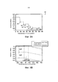
На фиг. 5А показан график 500 целевых значений ширины во множестве мест по длине одного слоя 110 согласно одному из примеров. Как показано на фиг. 5А, в данном примере целевые значения ширины могут изменяться во множестве мест 508 перехода ширины. На фиг. 5В показан увеличенный вид части графика 500, показанного на фиг. 5А в иллюстративном месте перехода. Кроме того, на фиг. 5В показана целевая ширина, основанная на спецификации 236 детали, максимально допустимая ширина слоя, основанная на пороговом значении для разницы между измеренной шириной и целевой шириной, а также минимально допустимая ширина, основанная на пороговом значении. В примере, показанном на фиг. 5В, пороговое значение составляет 0,03 дюйма. На фиг. 5В дополнительно показано место с максимально допустимым переходом ширины и место с минимально допустимым переходом ширины на основании целевой ширины и порогового значения в 0,1 дюйма для разницы в местах перехода ширины.FIG. 5A shows a plot of 500 target widths at multiple locations along the length of one
Если контроллер 217 принимает решение скорректировать процесс изготовления, затем корректируют процесс изготовления на основании произведенного сравнения измеренной ширины с целевой шириной в каждом месте. В одном из примеров контроллер 217 корректирует процесс изготовления путем корректировки, на основании разницы между измеренной шириной и целевой шириной в каждом месте, по меньшей мере одного параметра из спецификации 236 детали для резки следующего слоя. Например, если измеренная ширина слоя 110 меньше целевой ширины в первом месте, контроллер 217 может скорректировать параметр или параметры из спецификации 236 детали путем увеличения целевой ширины в первом месте для следующего слоя в спецификации 236 детали. Аналогичным образом, если измеренная ширина слоя 110 больше целевой ширины в первом месте, контроллер 217 может скорректировать параметр или параметры из спецификации 236 детали путем уменьшения целевой ширины в первом месте для следующего слоя в спецификации 236 детали. Таким образом, когда процесс изготовления приступает к выполнению резки следующего слоя 110, режущее устройство 218 будет запрограммировано следовать скорректированной траектории резки через материал для снижения выхода параметров за пределы допусков, выявленного при оценке слоя 110.If the
В дополнительных или альтернативных примерах контроллер 217 может скорректировать параметр или параметры из спецификации 236 детали путем увеличения и/или уменьшения целевой ширины более одного из остальных слоев 110 в стопе 112. Например, контроллер 217 может скорректировать параметр или параметры из спецификации 236 детали путем увеличения и/или уменьшения целевой ширины следующих двух слоев 110, следующих трех слоев 110, следующих четырех слоев 110 и т.д. в стопе 112. Это может обеспечить снижение выхода параметров за пределы допусков путем внесения меньших корректировок в многочисленные слои 110 вместо внесения относительной большой корректировки в одиночный слой 110.In additional or alternative examples,
В дополнительных или альтернативных примерах корректировка процесса изготовления включает добавление дополнительного материала к слою 110 в стопе 112. Например, контроллер 217 может определить, на основании разницы между измеренной шириной и целевой шириной в заданном месте, количество материала, которое необходимо добавить к слою 110 в месте. Определенное количество композитного материала в дальнейшем добавляют к слою 110 в месте для снижения выхода параметров за пределы допусков.In additional or alternative examples, adjusting the manufacturing process includes adding additional material to layer 110 in
В дополнительных или альтернативных примерах корректировка процесса изготовления включает удаление и резку заменяющего слоя 110 перед резкой следующего слоя в последовательности. Путем корректировки процесса изготовления на основании результата оценки слоя 110, перед резкой следующего слоя в последовательности, система 200 может эффективно реализовывать эти динамические корректировки в отношении процесса изготовления для реагирования на выход параметров за пределы допусков без задержек, что улучшает эффективность производства.In additional or alternative examples, adjusting the manufacturing process includes removing and cutting
В качестве дополнения или альтернативы в рамках приведенных примеров контроллер 217 оценивает слой 110 путем определения, на основании по меньшей двух краев 116, центровой линии 114 слоя и путем сравнения центровой линии 114 с опорной центровой линией. Например, контроллер 217 может определить центровую линию 114 путем определения набора точек в области 242 измерения, которые расположены на равном расстоянии друг от друга между кромками 116 слоя 110 по длине слоя 110. Опорная центровая линия может представлять собой центровую линию 114 первого слоя в последовательности. Контроллер 217 может сравнивать центровую линию 114 слоя 110 с опорной центровой линией путем определения разницы между центровой линией 114 слоя 110 и опорной центровой линией и определения, превышает ли разница пороговое значение.In addition or alternatively, within the above examples, the
В одном из примеров, если контроллер 217 определяет, что разница превышает пороговое значение, в дальнейшем слой 110 повторно размещают на стопе 112 для уменьшения разницы между центровой линией 114 слоя 110 и опорной центровой линией. Еще в одном примере, если контроллер 217 определяет, что разница превышает пороговое значение, в дальнейшем слой 110 удаляют из стопы 112 и повторно режут для уменьшения разницы между центровой линией 114 слоя 110 и опорной центровой линией.In one example, if the
Кроме того, в качестве дополнения или альтернативы в рамках приведенных примеров контроллер 217 оценивает слой 110 путем определения, на основании по меньшей двух краев 116, площади поверхности слоя. Контроллер 217 может определить, на основании определенной площади поверхности слоя 110 и известной толщины слоя 110, объем стопы 112, имеющейся в области 242 измерения после размещения слоя 110. Контроллер 217 в дальнейшем сравнивает измеренный объем с целевым объемом стопы 112, ожидаемым в области 242 измерения на этой стадии процесса изготовления. В спецификации 236 детали может быть указан целевой объем для каждой стадии процесса изготовления.In addition, as a supplement or alternative within the above examples, the
Контроллер 217 в дальнейшем принимает решение, на основании произведенного сравнения измеренного объема с целевым объемом, следует ли скорректировать по меньшей мере один параметр из спецификации 236 детали для резки следующего слоя в последовательности. Например, контроллер 217 может определить, превышает ли пороговое значение разница между измеренным объемом и целевым объемом и, если превышает, то в дальнейшем контроллер 217 может принять решение скорректировать параметр или параметры. Если контроллер 217 принимает решение скорректировать параметр или параметры, в дальнейшем это контроллер 217 может скорректировать по меньшей мере один параметр из спецификации 236 детали для резки следующего слоя.The
Например, если измеренный объем меньше целевого объема, контроллер 217 может скорректировать параметр или параметры из спецификации 236 детали путем увеличения целевой ширины в одном или более мест для следующего слоя в спецификации 236 детали. Аналогичным образом, если измеренный объем больше целевого объема, контроллер 217 может скорректировать параметр или параметры из спецификации 236 детали путем уменьшения целевой ширины в одном или более мест для следующего слоя в спецификации 236 детали. Таким образом, когда процесс изготовления приступает к выполнению резки следующего слоя, режущее устройство 218 будет запрограммировано следовать скорректированной траектории резки через материал для снижения риска наличия у композитной детали 100 неприемлемого объема после завершения процесса изготовления.For example, if the measured volume is less than the target volume, the
В дополнительных или альтернативных примерах корректировка процесса изготовления включает добавление дополнительного материала к слою 110 в стопе 112 и/или удаление и резку заменяющего слоя 110 перед резкой следующего слоя в последовательности для уменьшения риска наличия у композитной детали 100 неприемлемого объема.In additional or alternative examples, adjusting the manufacturing process includes adding additional material to layer 110 in
После резки всех слоев 110 и их размещения в стопе 112, отверждающее устройство 228 отверждает слои 110. Например, отверждающее устройство 228 может применять тепло и/или давление для отверждения стопы слоев с получением готовой композитной детали 100, размеры и свойства которой соответствуют конструкции из спецификации 236 детали.After all
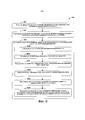
На фиг. 6 показана блок-схема процесса 600 получения композитной детали согласно одному из примеров. В блоке 610 процесс 600 включает резку, по одному слою за раз на основании спецификации детали, множества слоев материала в заданной последовательности. В спецификации детали указаны параметры процесса изготовления для получения композитной детали. В блоке 612 процесс 600 включает размещение, по одному слою за раз на основании спецификации детали, множества слоев с получением стопы в области измерения укладчика.FIG. 6 is a flow diagram of a
В блоке 614 процесс 600 включает, после размещения слоя и перед резкой следующего слоя в последовательности, выполнение для каждого слоя множества этапов, включающих блоки 614A-614F. Как показано в блоке 614А, этапы включают сканирование слоя по длине для определения изображения слоя. В блоке 614В этапы включают определение, на основании изображения, по меньшей двух краев слоя. В блоке 614С этапы включают определение, на основании по меньшей двух краев, измеренной ширины во множестве мест по длине слоя. В блоке 614D этапы включают сравнение измеренной ширины слоя в каждом месте с целевой шириной в месте. Параметры, указанные в спецификации детали, содержат целевую ширину в каждом месте по длине слоя.At
В блоке 614Е этапы включают принятие решения, на основании произведенного сравнения, следует ли скорректировать процесс изготовления. В блоке 614F, если указанным решением является проведение корректировки процесса изготовления в блоке 614Е, в дальнейшем этапы включают корректировку процесса изготовления на основании произведенного сравнения измеренной ширины с целевой шириной в каждом месте. По меньшей мере для одного слоя в блоке 614Е принимают решение скорректировать процесс изготовления.At
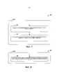
На фиг. 7-18 показаны дополнительные аспекты процесса 600 согласно дополнительным примерам. Как показано на фиг. 7, сканирование слоя по длине для определения изображения в блоке 614А может включать измерение соответствующей высоты в каждой точке для множества точек в области измерения в блоке 616 и определение изображения путем пространственного проецирования высоты, измеренной в каждой точке, на область измерения в блоке 618. Как показано на фиг. 8, обнаружение по меньшей двух краев в блоке 614В может включать определение первого набора из множества точек и второго набора из указанного множества точек, в которых изменение измеренной высоты превышает пороговое значение в блоке 720.FIG. 7-18 show additional aspects of the
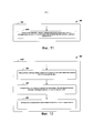
Как показано на фиг. 9, корректировка процесса изготовления в блоке 614F включает определение разницы между измеренной шириной и целевой шириной в первом месте из множества мест в блоке 622 и осуществление корректировки, на основании разницы, по меньшей мере одного параметра из спецификации детали для резки следующего слоя в последовательности в блоке 624.As shown in FIG. 9, adjusting the manufacturing process at
Как показано на фиг. 10, корректировка по меньшей мере одного параметра из спецификации детали в блоке 624 может включать увеличение целевой ширины в первом месте для следующего слоя в спецификации детали в блоке 624А, в которой измеренная ширина меньше целевой ширины в первом месте. Как показано на фиг. 11, корректировка по меньшей мере одного параметра из спецификации детали в блоке 624 может включать уменьшение целевой ширины в первом месте для следующего слоя в спецификации детали в блоке 624В, в которой измеренная ширина больше целевой ширины в первом месте.As shown in FIG. 10, adjusting at least one parameter from the BOM at
Как показано на фиг. 12, корректировка процесса изготовления в блоке 614F включает определение разницы между измеренной шириной и целевой шириной в первом месте из множества мест в блоке 626, определение, на основании разницы, количества материала, которое необходимо добавить к слою в первом месте в блоке 628, и добавление количества материала к слою в первом месте в блоке 630.As shown in FIG. 12, adjusting the manufacturing process at
Как показано на фиг. 13, корректировка процесса изготовления в блоке 614F включает удаление слоя из стопы в блоке 632, резку заменяющего слоя материала в блоке 634, а после резки заменяющего слоя в блоке 632 и удаления слоя из стопы в блоке 634 размещение заменяющего слоя на стопе в блоке 636.As shown in FIG. 13, adjusting the manufacturing process at
Как показано на фиг. 14, процесс 600 также может включать определение в блоке 638 опорной центровой линии первого слоя в заданной последовательности на основании указанных по меньшей двух краев, определенных для первого слоя в блоке 614С. В блоке 640 процесс 600 дополнительно включает, для каждого слоя в заданной последовательности после первого слоя, выполнение множества этапов, показанных в блоках 640A-640D. В блоке 640А этапы включают определение центровой линии слоя на основании по меньшей двух краев, определенных для слоя. В блоке 640В этапы включают определение разницы между центровой линией слоя и опорной центровой линией. В блоке 640С этапы включают определение, превышает ли разница пороговое значение. В блоке 640D в случае превышения разницей порогового значения, этапы включают повторное размещение слоя на стопе для уменьшения разницы между центровой линией слоя и опорной центровой линией.As shown in FIG. 14,
Как показано на фиг. 15, в блоке 642 процесс 600 также может включать, для каждого слоя, выполнение совокупностей этапов, показанных в блоках 642А-642Е. В блоке 642А процесс 600 включает определение, на основании по меньшей двух краев, площади поверхности слоя. В блоке 642 В процесс 600 включает определение, на основании площади поверхности, объема стопы, измеренного в области измерения. В блоке 642С процесс 600 включает сравнение измеренного объема с целевым объемом стопы в области измерения. Целевой объем указан в спецификации детали. В блоке 642D процесс 600 включает принятие решения, на основании произведенного сравнения измеренного объема с целевым объемом, следует ли скорректировать по меньшей мере один параметр из спецификации детали для резки следующего слоя в последовательности. В блоке 642Е, если указанным решением в блоке 642D является проведение корректировки по меньшей мере одного параметра из спецификации детали, процесс в дальнейшем осуществляет корректировку по меньшей мере одного параметра на основании произведенного сравнения. По меньшей мере для одного слоя принимают решение, на основании произведенного сравнения измеренного объема с целевым объемом в блоке 642D, скорректировать по меньшей мере один параметр.As shown in FIG. 15, at
Как показано на фиг. 16, корректировка по меньшей мере одного параметра из спецификации детали для резки следующего слоя в блоке 642Е включает уменьшение целевой ширины по меньшей мере для одного места по длине следующего слоя в блоке 644, в котором измеренный объем больше целевого объема. Как показано на фиг. 17, корректировка по меньшей мере одного параметра из спецификации детали для резки следующего слоя в блоке 642Е включает увеличение целевой ширины по меньшей мере для одного места по длине следующего слоя в блоке 646, в котором измеренный объем меньше целевого объема.As shown in FIG. 16, adjusting at least one parameter from the part specification for cutting the next layer in
Как показано на фиг. 18, сканирование слоя по длине в блоке 614А может включать в блоке 648 перемещение лазерного датчика смещения от первого конца области измерения до второго конца области измерения во второй плоскости, параллельной первой плоскости. Стопа расположена на плоской поверхности, проходящей в первой плоскости области измерения, которая расположена на заданном расстоянии от второй плоскости.As shown in FIG. 18, scanning the layer lengthwise at
V. Примеры измененийV. Examples of changes
В примере, показанном на фиг. 3А-3В, поверхность 240 укладки представляет собой плоскую поверхность, однако еще в одном примере поверхность 240 укладки может представлять собой поверхность на сердечнике, имеющем объемную форму. Кроме того, в примерах, показанных на фиг. 1А-1С и фиг. 3А-3В, слои имеют по существу прямоугольную форму, однако в дополнительных или альтернативных примерах слои могут иметь различные формы и размеры.In the example shown in FIG. 3A-3B, the stacking
Термины «по существу» или «приблизительно», использованные в данном документе, означают, что нет необходимости в достижении точного значения характеристики, параметра или значения, однако отклонения или изменения, в том числе, например, допуски, погрешность измерения, ограничения точности измерения и другие факторы, известные специалисту в данной области техники, могут возникнуть в значениях, которые не исключают эффект, на обеспечение которого направлена указанная характеристика.The terms "essentially" or "approximately" used in this document mean that it is not necessary to achieve the exact value of a characteristic, parameter or value, but deviations or changes, including, for example, tolerances, measurement uncertainty, limitations of measurement accuracy and other factors known to the person skilled in the art may occur at values that do not exclude the effect that the characteristic is intended to achieve.
Выше были описаны примеры аспектов. После изучения конфигураций, примеров и конструкций, описанных в данном документе, специалист в данной области техники сможет понять, что, однако, такие изменения и модификации могут быть реализованы без выхода за пределы объема и сущности настоящего изобретения. Описание различных предпочтительных аспектов было приведено для целей иллюстрации и описания, а не для того, чтобы его считали исчерпывающим или ограниченным раскрытой формой. После ознакомления с описанием настоящего изобретения специалистам в данной области техники станут очевидны многие модификации и изменения. Кроме того, различные предпочтительные аспекты могут обеспечить различные преимущества по сравнению с другими предпочтительными аспектами. Отбираемые примеры аспектов выбраны и описаны для пояснения принципов настоящего изобретения, практического применения, а также для обеспечения возможности другим специалистам в данной области техники понять настоящее изобретение с различными модификациями, подходящими для конкретного предполагаемого использования.Examples of aspects have been described above. Upon examination of the configurations, examples, and designs described herein, one skilled in the art will be able to understand that, however, such changes and modifications may be made without departing from the scope and spirit of the present invention. The various preferred aspects have been described for purposes of illustration and description, and not to be considered exhaustive or limited by the disclosed form. Many modifications and changes will become apparent to those skilled in the art upon reading the description of the present invention. In addition, different preferred aspects can provide different advantages over other preferred aspects. Selected example aspects are selected and described to illustrate the principles of the present invention, practical application, and also to enable others skilled in the art to understand the present invention with various modifications suitable for a particular intended use.
Кроме того, данный документ содержит примеры согласно приведенным далее пунктам.In addition, this document contains examples according to the points below.
1. Способ получения композитной детали, согласно которому:1. A method of obtaining a composite part, according to which:
выполняют резку, на основании спецификации детали, множества слоев материала в последовательности по одному слою за раз, при этом в спецификации детали указаны параметры процесса изготовления для получения композитной детали;cutting, based on the specification of the part, multiple layers of material in sequence, one layer at a time, while the specification of the part specifies the parameters of the manufacturing process to obtain the composite part;
размещают на основании спецификации детали, указанное множество слоев, по одному слою за раз с получением стопы в области измерения укладчика;placing on the basis of the specification of the part, the specified plurality of layers, one layer at a time to obtain a stack in the measurement area of the stacker;
для каждого слоя, после его размещения и перед резкой следующего слоя в последовательности:for each layer, after placing it and before cutting the next layer in sequence:
сканируют слой по длине для определения изображения слоя;scanning the layer lengthwise to determine the image of the layer;
определяют, на основании изображения, по меньшей два края слоя;determine, based on the image, at least two edges of the layer;
определяют, на основании указанных по меньшей двух краев, измеренную ширину во множестве мест по длине слоя;determining, based on the at least two edges, a measured width at a plurality of locations along the length of the layer;
производят сравнение измеренной ширины слоя в каждом месте с целевой шириной в этом месте, причем параметры, указанные в спецификации детали, содержат целевую ширину в каждом месте по длине слоя;comparing the measured width of the layer at each location with the target width at that location, the parameters specified in the part specification containing the target width at each location along the length of the layer;
на основании произведенного сравнения принимают решение, следует ли скорректировать процесс изготовления; иbased on the comparison made, a decision is made whether to adjust the manufacturing process; and
если указанным решением является проведение корректировки процесса изготовления, осуществляют корректировку процесса изготовления на основании произведенного сравнения измеренной ширины с целевой шириной в каждом месте,if the specified solution is to adjust the manufacturing process, adjust the manufacturing process based on the comparison of the measured width with the target width at each location,
причем по меньшей мере для одного слоя указанным решением является проведение корректировки процесса изготовления.moreover, for at least one layer, the specified solution is to adjust the manufacturing process.
2. Способ по пункту 1, согласно которому при сканировании слоя по длине для определения изображения:2. The method according to
измеряют соответствующую высоту в каждой точке из множества точек в области измерения иmeasure the corresponding height at each point of the plurality of points in the measurement area, and
определяют изображение путем пространственного проецирования высоты, измеренной в каждой точке, на область измерения.the image is determined by spatial projection of the height measured at each point onto the measurement area.
3. Способ по пункту 2, согласно которому при определении указанных по меньшей двух краев определяют первый набор указанного множества точек и второй набор указанного множества точек, в которых измеренная высота изменяется выше порогового значения.3. The method according to claim 2, according to which, when determining said at least two edges, a first set of said plurality of points and a second set of said plurality of points are determined at which the measured height changes above a threshold value.
4. Способ по пункту 1, согласно которому при корректировке процесса изготовления:4. The method according to
определяют разницу между измеренной шириной и целевой шириной в первом месте из указанного множества мест иdetermine the difference between the measured width and the target width at the first location of the specified set of locations, and
корректируют, на основании разницы, по меньшей мере один параметр спецификации детали для резки следующего слоя в последовательности.adjusting, based on the difference, at least one parameter of the part specification for cutting the next layer in the sequence.
5. Способ по пункту 4, согласно котором если измеренная ширина меньше целевой ширины в первом месте,5. The method of claim 4, wherein if the measured width is less than the target width at the first location,
корректировка по меньшей мере одного параметра из спецификации детали включает увеличение целевой ширины в первом месте для следующего слоя в спецификации детали.adjusting at least one parameter from the BOM includes increasing the target width at the first location for the next layer in the BOM.
6. Способ по пункту 4, согласно которому если измеренная ширина больше целевой ширины в первом месте,6. The method according to item 4, according to which if the measured width is greater than the target width in the first place,
корректировка по меньшей мере одного параметра из спецификации детали включает уменьшение целевой ширины в первом месте для следующего слоя в спецификации детали.adjusting at least one parameter from the BOM includes reducing the target width at the first location for the next layer in the BOM.
7. Способ по пункту 1, согласно которому при корректировке процесса изготовления:7. The method according to
определяют разницу между измеренной шириной и целевой шириной в первом месте из множества мест;determining the difference between the measured width and the target width in the first place of the plurality of places;
определяют, на основании разницы, количество материала, которое необходимо добавить к слою в первом месте; иdetermining, based on the difference, the amount of material to be added to the layer in the first place; and
добавляют указанное количество материала к слою в первом месте.add the specified amount of material to the layer in the first place.
8. Способ по пункту 1, согласно которому при корректировке процесса изготовления включает:8. The method according to
удаляют слой из стопы;remove the layer from the foot;
режут заменяющий слой материала; аcutting the replacement layer of material; a
после резки заменяющего слоя и удаления слоя из стопы, размещают заменяющий слой на стопе.after cutting the replacement layer and removing the layer from the foot, place the replacement layer on the foot.
9. Способ по пункту 1, согласно которому дополнительно:9. The method according to
определяют опорную центровую линию первого слоя в последовательности на основании указанных по меньшей мере двух краев, определенных для первого слоя;determining the reference centerline of the first layer in sequence based on the at least two edges defined for the first layer;
для каждого слоя в последовательности после первого слоя:for each layer in the sequence after the first layer:
определяют центровую линию слоя на основании по меньшей мере двух краев, определенных для слоя;determining the center line of the layer based on at least two edges defined for the layer;
определяют разницу между центровой линией слоя и опорной центровой линией;determine the difference between the center line of the layer and the reference center line;
определяют, превышает ли разница пороговое значение; иdetermine if the difference exceeds a threshold value; and
в случае превышения разницей порогового значения, повторно размещают слой на стопе для уменьшения разницы между центровой линией слоя и опорной центровой линией.if the difference exceeds the threshold value, re-place the layer on the stack to reduce the difference between the centerline of the layer and the reference centerline.
10. Способ по пункту 1, согласно которому дополнительно:10. The method according to
для каждого слоя:for each layer:
определяют, на основании указанных по меньшей двух краев, площадь поверхности слоя;determine, based on the specified at least two edges, the surface area of the layer;
определяют, на основании площади поверхности, измеренный объем стопы в области измерения;determining, based on the surface area, the measured volume of the foot in the measurement area;
сравнивают измеренный объем с целевым объемом стопы в области измерения, причем целевой объем указан в спецификации детали;comparing the measured volume to the target foot volume in the measurement area, the target volume being specified in the part specification;
принимают решение, на основании произведенного сравнения измеренного объема с целевым объемом, следует ли скорректировать по меньшей мере один параметр из спецификации детали для резки следующего слоя в последовательности; иmaking a decision, based on the comparison of the measured volume with the target volume, whether at least one parameter from the part specification should be corrected for cutting the next layer in the sequence; and
если указанным решением является проведение корректировки по меньшей мере одного параметра из спецификации детали, корректируют по меньшей мере один параметр на основании произведенного сравнения,if the solution is to correct at least one parameter from the part specification, correct at least one parameter based on the comparison made,
причем по меньшей мере для одного слоя решением, основанным на произведенном сравнении измеренного объема с целевым объемом, является проведение корректировки указанного по меньшей мере одного параметра.moreover, for at least one layer, the decision based on the comparison of the measured volume with the target volume is to correct the specified at least one parameter.
11. Способ по пункту 10, согласно которому если измеренный объем больше целевого объема,11. The method according to claim 10, according to which if the measured volume is greater than the target volume,
корректировка по меньшей мере одного параметра из спецификации детали для резки следующего слоя включает уменьшение целевой ширины по меньшей мере для одного места по длине следующего слоя.adjusting at least one parameter from the part specification for cutting the next layer includes reducing the target width for at least one location along the length of the next layer.
12. Способ по пункту 10, согласно которому если измеренный объем меньше целевого объема,12. The method according to paragraph 10, according to which if the measured volume is less than the target volume,
корректировка по меньшей мере одного параметра из спецификации детали для резки следующего слоя включает увеличение целевой ширины по меньшей мере для одного места по длине следующего слоя.adjusting at least one parameter from the part specification for cutting the next layer includes increasing the target width for at least one location along the length of the next layer.
13. Способ по пункту 1, согласно которому стопу размещают на плоской поверхности, проходящей в первой плоскости области измерения,13. The method according to
при этом сканирование слоя по длине слоя включает перемещение лазерного датчика смещения от первого конца области измерения ко второму концу области измерения во второй плоскости, параллельной первой плоскости,wherein scanning the layer along the length of the layer includes moving the laser displacement sensor from the first end of the measurement area to the second end of the measurement area in a second plane parallel to the first plane,
причем первая плоскость расположена на заданном расстоянии от второй плоскости.wherein the first plane is located at a predetermined distance from the second plane.
14. Система для получения композитной детали, содержащая:14. A system for obtaining a composite part, containing:
режущее устройство для резки множества слоев материала по одному слою за раз;a cutting device for cutting multiple layers of material one layer at a time;
область измерения для приема указанного множества слоев, по одному слою за раз, с получением стопы;a measurement area for receiving said plurality of layers, one layer at a time, to form a stack;
измерительное устройство для сканирования области измерения иmeasuring device for scanning the measuring area and
контроллер, выполненный с возможностью:controller configured to:
побуждать режущее устройство выполнять резку, на основании спецификации детали, указанного множества слоев в заданной последовательности по одному слою за раз, причем в спецификации детали указаны параметры процесса изготовления для получения композитной детали, иcause the cutter to cut, based on the part specification, the specified plurality of layers in a predetermined sequence, one layer at a time, the part specification specifying the manufacturing process parameters for the composite part, and
для каждого слоя, после приема слоя в области измерения и перед резкой режущим устройством следующего слоя в последовательности:for each layer, after receiving the layer in the measurement area and before cutting the next layer by the cutting device in the sequence:
побуждать измерительное устройство сканировать слой по длине для определения изображения слоя;cause the measuring device to scan the layer lengthwise to determine the image of the layer;
определять, на основании изображения, по меньшей два края слоя;determine, based on the image, at least two edges of the layer;
определять, на основании по меньшей двух краев, измеренную ширину во множестве мест по длине слоя;determine, based on at least two edges, a measured width at a plurality of locations along the length of the layer;
сравнивать измеренную ширину слоя в каждом месте с целевой шириной в месте, причем параметры, указанные в спецификации детали, содержат целевую ширину в каждом месте по длине слоя;compare the measured width of the layer at each location with the target width at the location, the parameters specified in the part specification containing the target width at each location along the length of the layer;
принимать решение, на основании произведенного сравнения, следует ли скорректировать процесс изготовления; иmake a decision, based on the comparison made, whether the manufacturing process should be adjusted; and
если указанным решением является проведение корректировки процесса изготовления, осуществлять корректировку, на основании произведенного сравнения, по меньшей мере одного параметра из спецификации детали для резки следующего слоя в последовательности,if the specified solution is to adjust the manufacturing process, carry out the adjustment, based on the comparison made, at least one parameter from the specification of the part for cutting the next layer in sequence,
причем по меньшей мере для одного слоя указанным решением является проведение корректировки процесса изготовления.moreover, for at least one layer, the specified solution is to adjust the manufacturing process.
15. Система по пункту 14, в которой измерительное устройство представляет собой лазерный датчик смещения.15. The system of claim 14, wherein the measuring device is a laser displacement sensor.
16. Система по пункту 14, в которой контроллер дополнительно выполнен с возможностью:16. The system according to paragraph 14, in which the controller is additionally configured to:
определять опорную центровую линию первого слоя в последовательности на основании по меньшей двух краев, определенных для первого слоя;determine the reference center line of the first layer in the sequence based on at least two edges defined for the first layer;
для каждого слоя в последовательности после первого слоя:for each layer in the sequence after the first layer:
определять центровую линию слоя на основании по меньшей двух краев, определенных для слоя;determine the center line of the layer based on at least two edges defined for the layer;
определять разницу между центровой линией слоя и опорной центровой линией;determine the difference between the center line of the layer and the reference center line;
определять, превышает ли разница пороговое значение; иdetermine if the difference exceeds a threshold value; and
в случае превышения разницей порогового значения, повторно размещать слой на стопе для уменьшения разницы между центровой линией слоя и опорной центровой линией.if the difference exceeds the threshold value, re-place the layer on the foot to reduce the difference between the centerline of the layer and the reference centerline.
17. Система по пункту 14, в которой контроллер дополнительно выполнен с возможностью:17. The system according to paragraph 14, in which the controller is additionally configured to:
для каждого слоя:for each layer:
определять, на основании по меньшей двух краев, площадь поверхности слоя;determine, based on at least two edges, the surface area of the layer;
определять, на основании площади поверхности, измеренный объем стопы в области измерения;determine, based on the surface area, the measured volume of the foot in the measurement area;
сравнивать измеренный объем с целевым объемом стопы в области измерения, причем целевой объем указан в спецификации детали;compare the measured volume with the target foot volume in the measurement area, the target volume being specified in the part specification;
принимать решение, на основании произведенного сравнения измеренного объема с целевым объемом, следует ли скорректировать по меньшей мере один параметр из спецификации детали для резки следующего слоя в последовательности; иdecide, based on the comparison of the measured volume with the target volume, whether at least one parameter from the part specification should be corrected for cutting the next layer in the sequence; and
если указанным решением является проведение корректировки по меньшей мере одного параметра из спецификации детали, осуществлять корректировку указанного по меньшей мере одного параметра на основании произведенного сравнения,if the specified solution is to correct at least one parameter from the specification of the part, to correct the specified at least one parameter based on the comparison made,
причем по меньшей мере для одного слоя решением, основанном на произведенном сравнении измеренного объема с целевым объемом, является проведение корректировки указанного по меньшей мере одного параметра из спецификации детали.moreover, for at least one layer, the decision based on the comparison of the measured volume with the target volume is to correct the specified at least one parameter from the part specification.
18. Некратковременный компьютерочитаемый носитель данных, содержащий хранящиеся на нем, программные инструкции, которые при их исполнении контроллером побуждают систему изготовления композитных деталей выполнять ряд действий,18. A non-transient computer-readable storage medium containing program instructions stored on it, which, when executed by the controller, induce the system for the manufacture of composite parts to perform a number of actions,
причем система изготовления композитных деталей содержит режущее устройство для резки множества слоев материала, область измерения для приема множества слоев с получением стопы, и измерительное устройство для сканирования области измерения, аwherein the system for manufacturing composite parts comprises a cutting device for cutting a plurality of layers of material, a measurement area for receiving a plurality of layers to form a stack, and a measurement device for scanning the measurement area, and
ряд операций включает:a number of operations include:
резку режущим устройством, на основании спецификации детали, множества слоев в последовательности по одному слою за раз, причем в спецификации детали указаны параметры процесса изготовления для получения композитной детали;cutting with a cutting device, based on the part specification, multiple layers in sequence, one layer at a time, and the part specification specifies the manufacturing process parameters for obtaining the composite part;
размещение, на основании спецификации детали, указанного множества слоев по одному слою за раз с получением стопы в области измерения; иplacing, based on the specification of the part, the specified plurality of layers one layer at a time to obtain a stack in the measurement area; and
для каждого слоя, после размещения слоя и перед резкой следующего слоя в последовательности:for each layer, after placing the layer and before cutting the next layer in sequence:
сканирование, посредством измерительного устройства, слоя по длине для определения изображения слоя;scanning, by means of a measuring device, the layer along its length to determine the image of the layer;
определение, на основании изображения, по меньшей двух краев слоя;determining, based on the image, at least two edges of the layer;
определение, на основании по меньшей двух краев, измеренной ширины во множестве мест по длине слоя;determining, based on at least two edges, a measured width at a plurality of locations along the length of the layer;
сравнение измеренной ширины слоя в каждом месте с целевой шириной в месте, причем параметры, указанные в спецификации детали, содержат целевую ширину в каждом месте по длине слоя;comparing the measured width of the layer at each location with the target width at the location, the parameters specified in the part specification containing the target width at each location along the length of the layer;
принятие решения, на основании произведенного сравнения, следует ли скорректировать процесс изготовления; иdeciding, based on the comparison made, whether the manufacturing process should be adjusted; and
если указанным решением является проведение корректировки процесса изготовления, осуществление корректировки, на основании произведенного сравнения, по меньшей мере одного параметра из спецификации детали для резки следующего слоя в последовательности,if the specified solution is to make adjustments to the manufacturing process, making adjustments, based on the comparison made, at least one parameter from the specification of the part for cutting the next layer in sequence,
причем по меньшей мере для одного слоя указанным решением является проведение корректировки процесса изготовления.moreover, for at least one layer, the specified solution is to adjust the manufacturing process.
19. Некратковременный компьютерочитаемый носитель данных по пункту 18, в котором указанный ряд действий дополнительно включает:19. Non-short-term computer-readable data carrier according to clause 18, in which the specified series of actions additionally includes:
определение опорной центровой линии первого слоя в последовательности на основании по меньшей двух краев, определенных для первого слоя;determining the reference center line of the first layer in the sequence based on at least two edges defined for the first layer;
для каждого слоя в последовательности после первого слоя:for each layer in the sequence after the first layer:
определение центровой линии слоя на основании по меньшей двух краев, определенных для слоя;determining the center line of the layer based on at least two edges defined for the layer;
определение разницы между центровой линией слоя и опорной центровой линией;determination of the difference between the center line of the layer and the reference center line;
определение, превышает ли разница пороговое значение; иdetermining if the difference exceeds a threshold value; and
в случае превышения разницей порогового значения, повторное размещение слоя на стопе для уменьшения разницы между центровой линией слоя и опорной центровой линией.if the difference exceeds the threshold value, re-position the layer on the foot to reduce the difference between the centerline of the layer and the reference centerline.
20. Некратковременный компьютерочитаемый носитель данных по пункту 18, в котором указанный ряд действий дополнительно включает:20. Non-short-term computer-readable data carrier according to clause 18, in which the specified series of actions additionally includes:
для каждого слоя:for each layer:
определение, на основании по меньшей двух краев, площади поверхности слоя;determining, based on at least two edges, the surface area of the layer;
определение, на основании площади поверхности, объема стопы, измеренного в области измерения;determining, based on the surface area, the volume of the foot measured in the measurement area;
сравнение измеренного объема с целевым объемом стопы в области измерения, причем целевой объем указан в спецификации детали;comparing the measured volume with the target foot volume in the measurement area, the target volume being specified in the part specification;
принятие решения, на основании произведенного сравнения измеренного объема с целевым объемом, следует ли скорректировать по меньшей мере один параметр из спецификации детали для резки следующего слоя в последовательности; иdeciding, based on the comparison of the measured volume with the target volume, whether at least one parameter from the part specification should be corrected for cutting the next layer in the sequence; and
если указанным решением является проведение корректировки по меньшей мере одного параметра из спецификации детали, осуществление последующей корректировки по меньшей мере одного параметра на основании произведенного сравнения,if the specified solution is to carry out an adjustment of at least one parameter from the part specification, the implementation of a subsequent adjustment of at least one parameter based on the comparison made,
причем по меньшей мере для одного слоя решением, основанным на произведенном сравнении измеренного объема с целевым объемом, является проведение корректировки указанного по меньшей мере одного параметра из спецификации детали.moreover, for at least one layer, the decision based on the comparison of the measured volume with the target volume is to correct the specified at least one parameter from the part specification.
Claims (110)
Applications Claiming Priority (2)
| Application Number | Priority Date | Filing Date | Title |
|---|---|---|---|
| US15/412,674 US10562244B2 (en) | 2017-01-23 | 2017-01-23 | Systems and methods for forming a composite part based on volume |
| US15/412,674 | 2017-01-23 |
Publications (3)
| Publication Number | Publication Date |
|---|---|
| RU2017136732A RU2017136732A (en) | 2019-04-18 |
| RU2017136732A3 RU2017136732A3 (en) | 2021-07-14 |
| RU2755714C2 true RU2755714C2 (en) | 2021-09-20 |
Family
ID=60117523
Family Applications (1)
| Application Number | Title | Priority Date | Filing Date |
|---|---|---|---|
| RU2017136732A RU2755714C2 (en) | 2017-01-23 | 2017-10-18 | Systems and methods for producing composite part |
Country Status (6)
| Country | Link |
|---|---|
| US (1) | US10562244B2 (en) |
| EP (1) | EP3351370B1 (en) |
| JP (1) | JP7043238B2 (en) |
| CN (1) | CN108340593B (en) |
| BR (1) | BR102017025010B1 (en) |
| RU (1) | RU2755714C2 (en) |
Families Citing this family (4)
| Publication number | Priority date | Publication date | Assignee | Title |
|---|---|---|---|---|
| CN111775301B (en) * | 2020-06-18 | 2021-07-02 | 中民筑友有限公司 | Method for positioning die table on prefabricated part production line |
| CN112102397B (en) * | 2020-09-10 | 2021-05-11 | 敬科(深圳)机器人科技有限公司 | Method, equipment and system for positioning multilayer part and readable storage medium |
| DE102021109699A1 (en) * | 2021-04-16 | 2022-10-20 | Airbus Operations Gmbh | Process for producing composite components with a non-developable surface |
| CN113899333A (en) * | 2021-09-29 | 2022-01-07 | 苏州佳祺仕信息科技有限公司 | Distance measuring method and device, electronic equipment and storage medium |
Citations (5)
| Publication number | Priority date | Publication date | Assignee | Title |
|---|---|---|---|---|
| RU2145547C1 (en) * | 1994-12-19 | 2000-02-20 | ОТГ Ст. Галлен АГ | Method for manufacture of parts from thermoplastic materials reinforced by fibre (alterative embodiments) and part manufactured by this method |
| RU2395729C2 (en) * | 2006-02-01 | 2010-07-27 | Сэнт-Гобэн Перформанс Пластикс Корпорейшн | Manufacturing method of shaped composite materials, and composite washer |
| RU133773U1 (en) * | 2013-02-20 | 2013-10-27 | Российская Федерация, От Имени Которой Выступает Министерство Промышленности И Торговли Российской Федерации | SYSTEM OF AUTOMATIC MANUFACTURE OF COMPLEX PROTOTYPES OF PARTS BY THE METHOD OF LAYERED CURING OF POLYMERS |
| RU2524233C2 (en) * | 2008-07-29 | 2014-07-27 | Эйрбас Оперэйшнз Лимитед | Method of composite element production |
| US20150106062A1 (en) * | 2013-10-16 | 2015-04-16 | General Electric Company | System and methods of generating a computer model of composite component |
Family Cites Families (17)
| Publication number | Priority date | Publication date | Assignee | Title |
|---|---|---|---|---|
| JPS61290038A (en) * | 1985-06-19 | 1986-12-20 | Agency Of Ind Science & Technol | Automatic sticking method for for tape and its device |
| US5954917A (en) | 1997-06-02 | 1999-09-21 | Boeing North American, Inc. | Automated material delivery system |
| EP1261787A2 (en) | 2000-02-25 | 2002-12-04 | The Boeing Company | Laminated composite radius filler |
| US7879177B2 (en) | 2006-11-20 | 2011-02-01 | The Boeing Company | Apparatus and method for composite material trim-on-the-fly |
| US9034128B2 (en) | 2007-12-17 | 2015-05-19 | The Boeing Company | Fitting doublers using gap mapping |
| US8180479B2 (en) | 2008-02-05 | 2012-05-15 | The Boeing Company | Adaptive control of composite plycutting |
| US8524020B2 (en) * | 2009-06-16 | 2013-09-03 | The Boeing Company | Method of restoring a composite airframe |
| US8568545B2 (en) * | 2009-06-16 | 2013-10-29 | The Boeing Company | Automated material removal in composite structures |
| US10169492B2 (en) * | 2011-06-20 | 2019-01-01 | The Boeing Company | Fiber placement optimization for steered-fiber plies |
| US9969131B2 (en) * | 2011-06-22 | 2018-05-15 | The Boeing Company | Automated ply layup system |
| US9897440B2 (en) * | 2014-01-17 | 2018-02-20 | The Boeing Company | Method and system for determining and verifying ply orientation of a composite laminate |
| US9606527B2 (en) * | 2014-06-30 | 2017-03-28 | Caterpillar Inc. | Automated fabrication system implementing 3-D void modeling |
| KR101730787B1 (en) * | 2014-07-08 | 2017-04-27 | 닛산 지도우샤 가부시키가이샤 | Defect detection device and production system |
| US9645095B2 (en) * | 2014-10-06 | 2017-05-09 | The Boeing Company | System and method for inspecting a composite part during manufacture |
| US9618459B2 (en) | 2015-05-18 | 2017-04-11 | Flightware, Inc. | Systems and methods for automated composite layup quality assurance |
| US10668673B2 (en) * | 2015-05-18 | 2020-06-02 | Flightware, Inc. | Systems and methods for automated composite layup quality assurance |
| US10794834B2 (en) * | 2015-06-08 | 2020-10-06 | National Research Council Of Canada | Real-time inspection of automated ribbon placement |
-
2017
- 2017-01-23 US US15/412,674 patent/US10562244B2/en active Active
- 2017-10-13 EP EP17196303.6A patent/EP3351370B1/en active Active
- 2017-10-18 RU RU2017136732A patent/RU2755714C2/en active
- 2017-11-22 BR BR102017025010-5A patent/BR102017025010B1/en active IP Right Grant
- 2017-12-07 JP JP2017234833A patent/JP7043238B2/en active Active
- 2017-12-25 CN CN201711419124.3A patent/CN108340593B/en active Active
Patent Citations (5)
| Publication number | Priority date | Publication date | Assignee | Title |
|---|---|---|---|---|
| RU2145547C1 (en) * | 1994-12-19 | 2000-02-20 | ОТГ Ст. Галлен АГ | Method for manufacture of parts from thermoplastic materials reinforced by fibre (alterative embodiments) and part manufactured by this method |
| RU2395729C2 (en) * | 2006-02-01 | 2010-07-27 | Сэнт-Гобэн Перформанс Пластикс Корпорейшн | Manufacturing method of shaped composite materials, and composite washer |
| RU2524233C2 (en) * | 2008-07-29 | 2014-07-27 | Эйрбас Оперэйшнз Лимитед | Method of composite element production |
| RU133773U1 (en) * | 2013-02-20 | 2013-10-27 | Российская Федерация, От Имени Которой Выступает Министерство Промышленности И Торговли Российской Федерации | SYSTEM OF AUTOMATIC MANUFACTURE OF COMPLEX PROTOTYPES OF PARTS BY THE METHOD OF LAYERED CURING OF POLYMERS |
| US20150106062A1 (en) * | 2013-10-16 | 2015-04-16 | General Electric Company | System and methods of generating a computer model of composite component |
Also Published As
| Publication number | Publication date |
|---|---|
| RU2017136732A (en) | 2019-04-18 |
| US10562244B2 (en) | 2020-02-18 |
| EP3351370B1 (en) | 2022-05-18 |
| JP7043238B2 (en) | 2022-03-29 |
| BR102017025010B1 (en) | 2022-11-22 |
| US20180207891A1 (en) | 2018-07-26 |
| CN108340593A (en) | 2018-07-31 |
| JP2018149795A (en) | 2018-09-27 |
| EP3351370A1 (en) | 2018-07-25 |
| BR102017025010A2 (en) | 2018-08-14 |
| RU2017136732A3 (en) | 2021-07-14 |
| CN108340593B (en) | 2021-08-06 |
Similar Documents
| Publication | Publication Date | Title |
|---|---|---|
| RU2755714C2 (en) | Systems and methods for producing composite part | |
| US11225026B2 (en) | Bead-type additive manufacturing system and method | |
| CN105365227B (en) | System and method for inspecting fiber placement during manufacture of fiber-reinforced composite components | |
| CN106273453B (en) | Stereoscopic printing device and its printing error bearing calibration | |
| JP6749582B2 (en) | Three-dimensional data generation device, three-dimensional modeling device, method of manufacturing modeled object, and program | |
| US8165702B2 (en) | Article manufacturing process | |
| CA2993985C (en) | Flat composites having layup features for forming into 3d shapes | |
| US11179900B2 (en) | Laminate shear forming machine with dynamic pressure adjustment | |
| US10875271B2 (en) | Gap fillers for composite materials | |
| CN108290355B (en) | Lay-up table for designing composite component, method for laying up preform of composite component, computer-readable storage medium and apparatus | |
| JP7294890B2 (en) | Method and system for adjusting toe placement system | |
| EP3597413B1 (en) | Method and system for tuning a tow placement system | |
| KR102275942B1 (en) | Method for trimming composite for aircraft | |
| US11225036B2 (en) | Method and system for tuning a tow placement system | |
| US11819916B2 (en) | Device and method for repairing components by means of additive manufacturing | |
| KR20220082311A (en) | A method for correcting errors in 3d printing | |
| JP2018001659A (en) | Three-dimensional data generation device, three-dimensional molding device, molded object manufacturing method and program | |
| Meng | A paper to be submitted to Composites: Part A Fanqi Meng, Matthew C. Frank, Frank E. Peters 2 |