RU2753503C1 - Vehicle temperature control system - Google Patents
Vehicle temperature control system Download PDFInfo
- Publication number
- RU2753503C1 RU2753503C1 RU2021105655A RU2021105655A RU2753503C1 RU 2753503 C1 RU2753503 C1 RU 2753503C1 RU 2021105655 A RU2021105655 A RU 2021105655A RU 2021105655 A RU2021105655 A RU 2021105655A RU 2753503 C1 RU2753503 C1 RU 2753503C1
- Authority
- RU
- Russia
- Prior art keywords
- heat
- vehicle
- distribution state
- coolant
- temperature
- Prior art date
Links
Images

Classifications
-
- B—PERFORMING OPERATIONS; TRANSPORTING
- B60—VEHICLES IN GENERAL
- B60H—ARRANGEMENTS OF HEATING, COOLING, VENTILATING OR OTHER AIR-TREATING DEVICES SPECIALLY ADAPTED FOR PASSENGER OR GOODS SPACES OF VEHICLES
- B60H1/00—Heating, cooling or ventilating devices
- B60H1/00642—Control systems or circuits; Control members or indication devices for heating, cooling or ventilating devices
- B60H1/00814—Control systems or circuits characterised by their output, for controlling particular components of the heating, cooling or ventilating installation
- B60H1/00878—Control systems or circuits characterised by their output, for controlling particular components of the heating, cooling or ventilating installation the components being temperature regulating devices
-
- B—PERFORMING OPERATIONS; TRANSPORTING
- B60—VEHICLES IN GENERAL
- B60H—ARRANGEMENTS OF HEATING, COOLING, VENTILATING OR OTHER AIR-TREATING DEVICES SPECIALLY ADAPTED FOR PASSENGER OR GOODS SPACES OF VEHICLES
- B60H1/00—Heating, cooling or ventilating devices
- B60H1/02—Heating, cooling or ventilating devices the heat being derived from the propulsion plant
- B60H1/14—Heating, cooling or ventilating devices the heat being derived from the propulsion plant other than from cooling liquid of the plant
- B60H1/18—Heating, cooling or ventilating devices the heat being derived from the propulsion plant other than from cooling liquid of the plant the air being heated from the plant exhaust gases
- B60H1/20—Heating, cooling or ventilating devices the heat being derived from the propulsion plant other than from cooling liquid of the plant the air being heated from the plant exhaust gases using an intermediate heat-transferring medium
-
- B—PERFORMING OPERATIONS; TRANSPORTING
- B60—VEHICLES IN GENERAL
- B60K—ARRANGEMENT OR MOUNTING OF PROPULSION UNITS OR OF TRANSMISSIONS IN VEHICLES; ARRANGEMENT OR MOUNTING OF PLURAL DIVERSE PRIME-MOVERS IN VEHICLES; AUXILIARY DRIVES FOR VEHICLES; INSTRUMENTATION OR DASHBOARDS FOR VEHICLES; ARRANGEMENTS IN CONNECTION WITH COOLING, AIR INTAKE, GAS EXHAUST OR FUEL SUPPLY OF PROPULSION UNITS IN VEHICLES
- B60K11/00—Arrangement in connection with cooling of propulsion units
- B60K11/02—Arrangement in connection with cooling of propulsion units with liquid cooling
-
- B—PERFORMING OPERATIONS; TRANSPORTING
- B60—VEHICLES IN GENERAL
- B60H—ARRANGEMENTS OF HEATING, COOLING, VENTILATING OR OTHER AIR-TREATING DEVICES SPECIALLY ADAPTED FOR PASSENGER OR GOODS SPACES OF VEHICLES
- B60H1/00—Heating, cooling or ventilating devices
-
- B—PERFORMING OPERATIONS; TRANSPORTING
- B60—VEHICLES IN GENERAL
- B60H—ARRANGEMENTS OF HEATING, COOLING, VENTILATING OR OTHER AIR-TREATING DEVICES SPECIALLY ADAPTED FOR PASSENGER OR GOODS SPACES OF VEHICLES
- B60H1/00—Heating, cooling or ventilating devices
- B60H1/00271—HVAC devices specially adapted for particular vehicle parts or components and being connected to the vehicle HVAC unit
- B60H1/00278—HVAC devices specially adapted for particular vehicle parts or components and being connected to the vehicle HVAC unit for the battery
-
- B—PERFORMING OPERATIONS; TRANSPORTING
- B60—VEHICLES IN GENERAL
- B60H—ARRANGEMENTS OF HEATING, COOLING, VENTILATING OR OTHER AIR-TREATING DEVICES SPECIALLY ADAPTED FOR PASSENGER OR GOODS SPACES OF VEHICLES
- B60H1/00—Heating, cooling or ventilating devices
- B60H1/00357—Air-conditioning arrangements specially adapted for particular vehicles
- B60H1/00385—Air-conditioning arrangements specially adapted for particular vehicles for vehicles having an electrical drive, e.g. hybrid or fuel cell
- B60H1/004—Air-conditioning arrangements specially adapted for particular vehicles for vehicles having an electrical drive, e.g. hybrid or fuel cell for vehicles having a combustion engine and electric drive means, e.g. hybrid electric vehicles
-
- B—PERFORMING OPERATIONS; TRANSPORTING
- B60—VEHICLES IN GENERAL
- B60H—ARRANGEMENTS OF HEATING, COOLING, VENTILATING OR OTHER AIR-TREATING DEVICES SPECIALLY ADAPTED FOR PASSENGER OR GOODS SPACES OF VEHICLES
- B60H1/00—Heating, cooling or ventilating devices
- B60H1/00642—Control systems or circuits; Control members or indication devices for heating, cooling or ventilating devices
- B60H1/00814—Control systems or circuits characterised by their output, for controlling particular components of the heating, cooling or ventilating installation
- B60H1/00878—Control systems or circuits characterised by their output, for controlling particular components of the heating, cooling or ventilating installation the components being temperature regulating devices
- B60H1/00885—Controlling the flow of heating or cooling liquid, e.g. valves or pumps
-
- B—PERFORMING OPERATIONS; TRANSPORTING
- B60—VEHICLES IN GENERAL
- B60H—ARRANGEMENTS OF HEATING, COOLING, VENTILATING OR OTHER AIR-TREATING DEVICES SPECIALLY ADAPTED FOR PASSENGER OR GOODS SPACES OF VEHICLES
- B60H1/00—Heating, cooling or ventilating devices
- B60H1/00642—Control systems or circuits; Control members or indication devices for heating, cooling or ventilating devices
- B60H1/00814—Control systems or circuits characterised by their output, for controlling particular components of the heating, cooling or ventilating installation
- B60H1/00878—Control systems or circuits characterised by their output, for controlling particular components of the heating, cooling or ventilating installation the components being temperature regulating devices
- B60H1/00899—Controlling the flow of liquid in a heat pump system
-
- B—PERFORMING OPERATIONS; TRANSPORTING
- B60—VEHICLES IN GENERAL
- B60H—ARRANGEMENTS OF HEATING, COOLING, VENTILATING OR OTHER AIR-TREATING DEVICES SPECIALLY ADAPTED FOR PASSENGER OR GOODS SPACES OF VEHICLES
- B60H1/00—Heating, cooling or ventilating devices
- B60H1/02—Heating, cooling or ventilating devices the heat being derived from the propulsion plant
- B60H1/03—Heating, cooling or ventilating devices the heat being derived from the propulsion plant and from a source other than the propulsion plant
-
- B—PERFORMING OPERATIONS; TRANSPORTING
- B60—VEHICLES IN GENERAL
- B60H—ARRANGEMENTS OF HEATING, COOLING, VENTILATING OR OTHER AIR-TREATING DEVICES SPECIALLY ADAPTED FOR PASSENGER OR GOODS SPACES OF VEHICLES
- B60H1/00—Heating, cooling or ventilating devices
- B60H1/02—Heating, cooling or ventilating devices the heat being derived from the propulsion plant
- B60H1/14—Heating, cooling or ventilating devices the heat being derived from the propulsion plant other than from cooling liquid of the plant
- B60H1/143—Heating, cooling or ventilating devices the heat being derived from the propulsion plant other than from cooling liquid of the plant the heat being derived from cooling an electric component, e.g. electric motors, electric circuits, fuel cells or batteries
-
- B—PERFORMING OPERATIONS; TRANSPORTING
- B60—VEHICLES IN GENERAL
- B60H—ARRANGEMENTS OF HEATING, COOLING, VENTILATING OR OTHER AIR-TREATING DEVICES SPECIALLY ADAPTED FOR PASSENGER OR GOODS SPACES OF VEHICLES
- B60H1/00—Heating, cooling or ventilating devices
- B60H1/22—Heating, cooling or ventilating devices the heat source being other than the propulsion plant
-
- B—PERFORMING OPERATIONS; TRANSPORTING
- B60—VEHICLES IN GENERAL
- B60H—ARRANGEMENTS OF HEATING, COOLING, VENTILATING OR OTHER AIR-TREATING DEVICES SPECIALLY ADAPTED FOR PASSENGER OR GOODS SPACES OF VEHICLES
- B60H1/00—Heating, cooling or ventilating devices
- B60H1/32—Cooling devices
- B60H1/3204—Cooling devices using compression
- B60H1/3205—Control means therefor
- B60H1/3213—Control means therefor for increasing the efficiency in a vehicle heat pump
-
- B—PERFORMING OPERATIONS; TRANSPORTING
- B60—VEHICLES IN GENERAL
- B60H—ARRANGEMENTS OF HEATING, COOLING, VENTILATING OR OTHER AIR-TREATING DEVICES SPECIALLY ADAPTED FOR PASSENGER OR GOODS SPACES OF VEHICLES
- B60H1/00—Heating, cooling or ventilating devices
- B60H1/32—Cooling devices
- B60H1/3204—Cooling devices using compression
- B60H1/3228—Cooling devices using compression characterised by refrigerant circuit configurations
- B60H1/32284—Cooling devices using compression characterised by refrigerant circuit configurations comprising two or more secondary circuits, e.g. at evaporator and condenser side
-
- F—MECHANICAL ENGINEERING; LIGHTING; HEATING; WEAPONS; BLASTING
- F01—MACHINES OR ENGINES IN GENERAL; ENGINE PLANTS IN GENERAL; STEAM ENGINES
- F01N—GAS-FLOW SILENCERS OR EXHAUST APPARATUS FOR MACHINES OR ENGINES IN GENERAL; GAS-FLOW SILENCERS OR EXHAUST APPARATUS FOR INTERNAL-COMBUSTION ENGINES
- F01N5/00—Exhaust or silencing apparatus combined or associated with devices profiting by exhaust energy
- F01N5/02—Exhaust or silencing apparatus combined or associated with devices profiting by exhaust energy the devices using heat
-
- F—MECHANICAL ENGINEERING; LIGHTING; HEATING; WEAPONS; BLASTING
- F01—MACHINES OR ENGINES IN GENERAL; ENGINE PLANTS IN GENERAL; STEAM ENGINES
- F01P—COOLING OF MACHINES OR ENGINES IN GENERAL; COOLING OF INTERNAL-COMBUSTION ENGINES
- F01P3/00—Liquid cooling
- F01P3/20—Cooling circuits not specific to a single part of engine or machine
-
- B—PERFORMING OPERATIONS; TRANSPORTING
- B60—VEHICLES IN GENERAL
- B60H—ARRANGEMENTS OF HEATING, COOLING, VENTILATING OR OTHER AIR-TREATING DEVICES SPECIALLY ADAPTED FOR PASSENGER OR GOODS SPACES OF VEHICLES
- B60H1/00—Heating, cooling or ventilating devices
- B60H1/00271—HVAC devices specially adapted for particular vehicle parts or components and being connected to the vehicle HVAC unit
- B60H2001/00307—Component temperature regulation using a liquid flow
-
- B—PERFORMING OPERATIONS; TRANSPORTING
- B60—VEHICLES IN GENERAL
- B60H—ARRANGEMENTS OF HEATING, COOLING, VENTILATING OR OTHER AIR-TREATING DEVICES SPECIALLY ADAPTED FOR PASSENGER OR GOODS SPACES OF VEHICLES
- B60H1/00—Heating, cooling or ventilating devices
- B60H1/00642—Control systems or circuits; Control members or indication devices for heating, cooling or ventilating devices
- B60H1/00814—Control systems or circuits characterised by their output, for controlling particular components of the heating, cooling or ventilating installation
- B60H1/00878—Control systems or circuits characterised by their output, for controlling particular components of the heating, cooling or ventilating installation the components being temperature regulating devices
- B60H2001/00928—Control systems or circuits characterised by their output, for controlling particular components of the heating, cooling or ventilating installation the components being temperature regulating devices comprising a secondary circuit
-
- F—MECHANICAL ENGINEERING; LIGHTING; HEATING; WEAPONS; BLASTING
- F01—MACHINES OR ENGINES IN GENERAL; ENGINE PLANTS IN GENERAL; STEAM ENGINES
- F01N—GAS-FLOW SILENCERS OR EXHAUST APPARATUS FOR MACHINES OR ENGINES IN GENERAL; GAS-FLOW SILENCERS OR EXHAUST APPARATUS FOR INTERNAL-COMBUSTION ENGINES
- F01N2240/00—Combination or association of two or more different exhaust treating devices, or of at least one such device with an auxiliary device, not covered by indexing codes F01N2230/00 or F01N2250/00, one of the devices being
- F01N2240/02—Combination or association of two or more different exhaust treating devices, or of at least one such device with an auxiliary device, not covered by indexing codes F01N2230/00 or F01N2250/00, one of the devices being a heat exchanger
-
- F—MECHANICAL ENGINEERING; LIGHTING; HEATING; WEAPONS; BLASTING
- F01—MACHINES OR ENGINES IN GENERAL; ENGINE PLANTS IN GENERAL; STEAM ENGINES
- F01N—GAS-FLOW SILENCERS OR EXHAUST APPARATUS FOR MACHINES OR ENGINES IN GENERAL; GAS-FLOW SILENCERS OR EXHAUST APPARATUS FOR INTERNAL-COMBUSTION ENGINES
- F01N2590/00—Exhaust or silencing apparatus adapted to particular use, e.g. for military applications, airplanes, submarines
- F01N2590/11—Exhaust or silencing apparatus adapted to particular use, e.g. for military applications, airplanes, submarines for hybrid vehicles
-
- F—MECHANICAL ENGINEERING; LIGHTING; HEATING; WEAPONS; BLASTING
- F01—MACHINES OR ENGINES IN GENERAL; ENGINE PLANTS IN GENERAL; STEAM ENGINES
- F01P—COOLING OF MACHINES OR ENGINES IN GENERAL; COOLING OF INTERNAL-COMBUSTION ENGINES
- F01P2060/00—Cooling circuits using auxiliaries
- F01P2060/08—Cabin heater
-
- F—MECHANICAL ENGINEERING; LIGHTING; HEATING; WEAPONS; BLASTING
- F01—MACHINES OR ENGINES IN GENERAL; ENGINE PLANTS IN GENERAL; STEAM ENGINES
- F01P—COOLING OF MACHINES OR ENGINES IN GENERAL; COOLING OF INTERNAL-COMBUSTION ENGINES
- F01P2060/00—Cooling circuits using auxiliaries
- F01P2060/16—Outlet manifold
-
- Y—GENERAL TAGGING OF NEW TECHNOLOGICAL DEVELOPMENTS; GENERAL TAGGING OF CROSS-SECTIONAL TECHNOLOGIES SPANNING OVER SEVERAL SECTIONS OF THE IPC; TECHNICAL SUBJECTS COVERED BY FORMER USPC CROSS-REFERENCE ART COLLECTIONS [XRACs] AND DIGESTS
- Y02—TECHNOLOGIES OR APPLICATIONS FOR MITIGATION OR ADAPTATION AGAINST CLIMATE CHANGE
- Y02T—CLIMATE CHANGE MITIGATION TECHNOLOGIES RELATED TO TRANSPORTATION
- Y02T10/00—Road transport of goods or passengers
- Y02T10/10—Internal combustion engine [ICE] based vehicles
- Y02T10/12—Improving ICE efficiencies
Landscapes
- Engineering & Computer Science (AREA)
- Mechanical Engineering (AREA)
- Physics & Mathematics (AREA)
- Thermal Sciences (AREA)
- Chemical & Material Sciences (AREA)
- Combustion & Propulsion (AREA)
- General Engineering & Computer Science (AREA)
- Sustainable Development (AREA)
- Sustainable Energy (AREA)
- Life Sciences & Earth Sciences (AREA)
- Transportation (AREA)
- Air-Conditioning For Vehicles (AREA)
- Cooling, Air Intake And Gas Exhaust, And Fuel Tank Arrangements In Propulsion Units (AREA)
- Hybrid Electric Vehicles (AREA)
Abstract
Description
Область техникиTechnology area
[0001] Настоящее изобретение относится к системе управления температурой в транспортном средстве.[0001] The present invention relates to a temperature control system in a vehicle.
Уровень техникиState of the art
[0002] Известна система управления температурой в транспортном средстве, использующая нагревательный сердечник, предусмотренный в тепловом контуре транспортного средства, для обогрева салона транспортного средства. В частности, в такой системе управления температурой в транспортном средстве известно, что теплоноситель, втекающий в сердечник нагревателя, нагревается теплотой выхлопных газов двигателя внутреннего сгорания и теплом, выделяемым из конденсатора контура охлаждения, реализованного отдельно от двигатель внутреннего сгорания (см., например, публикацию нерассмотренной заявки на патент Японии № 2009-180103 (JP 2009-180103 A).[0002] A vehicle temperature control system is known that uses a heating core provided in a heat circuit of a vehicle to heat a vehicle interior. In particular, in such a temperature control system in a vehicle, it is known that the coolant flowing into the heater core is heated by the heat of the exhaust gases of the internal combustion engine and the heat generated from the condenser of the cooling circuit, which is implemented separately from the internal combustion engine (see, for example, the publication Japanese Unexamined Patent Application No. 2009-180103 (JP 2009-180103 A).
Сущность изобретенияThe essence of the invention
[0003] Конструкция транспортного средства может потребовать установки двигателя внутреннего сгорания и сердечника нагревателя с расстоянием между ними. Это удлиняет трубу для теплоносителя, расположенную между двигателем внутреннего сгорания и сердечником нагревателя. Таким образом, когда теплоноситель, нагретый двигателем внутреннего сгорания, должен протекать через сердечник нагревателя, сначала в сердечник нагревателя течет холодный теплоноситель, остающийся в трубе. В результате, тепловая способность сердечника нагревателя в это время является малой.[0003] The vehicle design may require the internal combustion engine and heater core to be spaced apart. This lengthens the heating medium pipe located between the combustion engine and the heater core. Thus, when the coolant heated by the internal combustion engine is to flow through the heater core, the cold coolant remaining in the pipe first flows into the heater core. As a result, the heating capacity of the heater core at this time is low.
[0004] В частности, когда теплоноситель, текущий в сердечник нагревателя, может быть нагрет за счет тепла, выделяемого из конденсатора охлаждающего контура, высокотемпературный теплоноситель может подаваться из конденсатора в сердечник нагревателя до того, как теплоноситель будет нагревается двигателем внутреннего сгорания. Таким образом, даже если высокотемпературный теплоноситель был подан в сердечник нагревателя для использования для нагрева перед использованием теплоносителя, нагретого двигателем внутреннего сгорания, когда начинается использование теплоносителя, вытекающего из двигателя внутреннего сгорания, холодный теплоноситель временно втекает в сердечник нагревателя. В результате временно снижается тепловая мощность.[0004] Specifically, when the heating medium flowing into the heater core can be heated by the heat generated from the condenser of the cooling loop, the high temperature heating medium can be supplied from the condenser to the heater core before the heating medium is heated by the combustion engine. Thus, even if the high-temperature heat transfer medium has been supplied to the heater core to be used for heating before using the heat transfer medium heated by the internal combustion engine, when the use of the heat transfer medium from the internal combustion engine is started, the cold heat transfer medium temporarily flows into the heater core. As a result, the heat output is temporarily reduced.
[0005] Принимая во внимание вышеупомянутые проблемы, задачей настоящего изобретения является предотвращение снижения теплопроизводительности сердечника нагревателя из-за теплоносителя, который остается в трубопроводе теплоносителя между двигателем внутреннего сгорания и сердечником нагревателя, протекая через сердечник нагревателя.[0005] In view of the aforementioned problems, it is an object of the present invention to prevent the heating capacity of the heater core from decreasing due to the coolant that remains in the coolant pipe between the internal combustion engine and the heater core while flowing through the heater core.
[0006] Суть настоящего изобретения заключается в следующем.[0006] The essence of the present invention is as follows.
[0007] Аспект изобретения относится к системе управления температурой в транспортном средстве, содержащей: сердечник нагревателя, используемый для обогрева салона транспортного средства с использованием тепла теплоносителя; первый нагревательный блок, который нагревает теплоноситель с использованием тепла выхлопных газов двигателя внутреннего сгорания; тепловой контур, выполненный с возможностью обеспечения циркуляции теплоносителя между сердечником нагревателя и первым нагревательным блоком; механизм переключения состояний распределения, который переключает состояние распределения теплоносителя между первым состоянием распределения и вторым состоянием распределения; и устройство управления, которое управляет механизмом переключения состояний распределения, при этом: тепловой контур включает в себя обходной канал потока, расположенный параллельно сердечнику нагревателя по отношению к первому нагревательному блоку; в первом состоянии распределения теплоноситель, нагретый первым нагревательным блоком, протекает через сердечник нагревателя, не проходя по обходному каналу потока; во втором состоянии распределения теплоноситель, нагретый первым нагревательным блоком, протекает по обходному каналу потока, не проходя через сердечник нагревателя; и первый нагревательный блок расположен на первой стороне салона транспортного средства в продольном направлении транспортного средства, а сердечник нагревателя и обходной канал потока расположены на второй стороне, которая противоположна первой стороне салона транспортного средства в продольном направлении транспортного средства.[0007] An aspect of the invention relates to a temperature control system in a vehicle, comprising: a heater core used to heat a vehicle interior using heat from a heat transfer medium; a first heating unit that heats the heating medium using the heat from the exhaust gases of the internal combustion engine; a thermal circuit configured to circulate a heating medium between the heater core and the first heating unit; a distribution state switching mechanism that switches a distribution state of a heat medium between a first distribution state and a second distribution state; and a control device that controls a distribution state switching mechanism, wherein: the heat circuit includes a bypass flow path parallel to the heater core with respect to the first heating unit; in the first distribution state, the heating medium heated by the first heating unit flows through the heater core without passing through the bypass flow channel; in the second distribution state, the heating medium heated by the first heating unit flows through the bypass flow channel without passing through the heater core; and the first heating unit is located on the first side of the vehicle compartment in the longitudinal direction of the vehicle, and the heater core and the bypass flow path are located on the second side that is opposite to the first side of the vehicle compartment in the longitudinal direction of the vehicle.
[0008] В вышеупомянутом аспекте первая сторона салона транспортного средства может быть дальше в направлении назад от салона транспортного средства, а вторая сторона салона транспортного средства может быть дальше в направлении вперед от салона транспортного средства.[0008] In the above aspect, the first side of the vehicle interior may be further rearward from the vehicle interior, and the second side of the vehicle interior may be further forward from the vehicle interior.
[0009] В вышеупомянутом аспекте устройство управления может управлять механизмом переключения состояний распределения, чтобы переключать состояние распределения теплоносителя в порядке второго состояния распределения и первого состояния распределения, когда запрашивается обогрев салона транспортного средства.[0009] In the above aspect, the control device may control the distribution state switching mechanism to switch the distribution state of the coolant in the order of the second distribution state and the first distribution state when the vehicle interior heating is requested.
[0010] В вышеупомянутом аспекте система управления температурой в транспортном средстве может дополнительно включать в себя второй нагревательный блок, который нагревает теплоноситель с использованием тепла, отличного от тепла выхлопных газов двигателя внутреннего сгорания, при этом: механизм переключения состояний распределения может переключать состояние распределения теплоносителя между первым состоянием распределения, вторым состоянием распределения и третьим состоянием распределения; при этом в третьем состоянии распределения теплоноситель не может течь ни в сердечник нагревателя, ни в обходной канал потока от первого нагревательного блока, и теплоноситель, нагретый вторым нагревательным блоком, протекает через сердечник нагревателя; и второй нагревательный блок может быть расположен на второй стороне салона транспортного средства.[0010] In the aforementioned aspect, the vehicle temperature control system may further include a second heating unit that heats the heating medium using heat other than the exhaust heat of the internal combustion engine, wherein: the distribution state switching mechanism can switch the distribution state of the heating medium between a first distribution state, a second distribution state, and a third distribution state; wherein, in the third distribution state, the heat medium cannot flow into either the heater core or the bypass flow path from the first heating unit, and the heat medium heated by the second heating unit flows through the heater core; and the second heating unit may be located on the second side of the vehicle interior.
[0011] В вышеупомянутом аспекте в тепловом контуре, когда механизм переключения состояний распределения находится во втором состоянии распределения, теплоноситель, нагретый вторым нагревательным блоком, может протекать через сердечник нагревателя.[0011] In the above aspect, in the heat loop, when the distribution state switching mechanism is in the second distribution state, the heat medium heated by the second heating unit can flow through the heater core.
[0012] В вышеупомянутом аспекте тепловой контур может включать в себя тепловой контур двигателя, позволяющий, по меньшей мере, части теплоносителя, вытекающего из первого нагревательного блока, снова течь в первый нагревательный блок, не протекая через сердечник нагревателя или обходной канал потока; при этом тепловой контур двигателя может быть расположен на первой стороне салона транспортного средства; и в третьем состоянии распределения теплоноситель, нагретый первым нагревательным блоком, может циркулировать только в тепловом контуре двигателя.[0012] In the above aspect, the thermal circuit may include a motor thermal circuit allowing at least a portion of the heat transfer medium flowing out of the first heating unit to flow back into the first heating unit without flowing through the heater core or flow bypass; the thermal circuit of the engine can be located on the first side of the vehicle compartment; and in the third distribution state, the heating medium heated by the first heating unit can only circulate in the thermal circuit of the engine.
[0013] В вышеупомянутом аспекте устройство управления может быть сконфигурировано для управления механизмом переключения состояний распределения, чтобы переключать состояние распределения теплоносителя в порядке третьего состояния распределения, второго состояния распределения и первого состояния распределения при запросе обогрева салона транспортного средства.[0013] In the above aspect, the control device may be configured to control the distribution state switching mechanism to switch the distribution state of the coolant in the order of the third distribution state, the second distribution state, and the first distribution state when a vehicle interior heating is requested.
[0014] В вышеупомянутом аспекте система управления температурой в транспортном средстве может дополнительно включать в себя контур охлаждения, в котором второй нагревательный блок может нагревать теплоноситель с использованием тепла конденсатора контура охлаждения.[0014] In the above aspect, the vehicle temperature control system may further include a refrigeration circuit in which the second heating unit can heat a heating medium using heat from a condenser of the refrigeration circuit.
[0015] В вышеупомянутом аспекте тепловой контур может включать в себя первый тепловой контур и второй тепловой контур; первый тепловой контур может позволить теплоносителю циркулировать между первым нагревательным блоком и сердечником нагревателя; второй тепловой контур может позволить теплоносителю циркулировать между вторым нагревательным блоком и сердечником нагревателя; и первый тепловой контур может включать обходной канал потока.[0015] In the above aspect, the heat loop may include a first heat loop and a second heat loop; the first heating circuit can allow the heating medium to circulate between the first heating unit and the heater core; the second heating circuit can allow the heating medium to circulate between the second heating unit and the heater core; and the first thermal loop may include a bypass flow path.
[0016] В вышеупомянутом аспекте второй тепловой контур может включать в себя радиатор, предусмотренный параллельно сердечнику нагревателя по отношению ко второму нагревательному блоку; и второй тепловой контур может быть выполнен с возможностью регулирования расхода теплоносителя, протекающего через сердечник нагревателя и радиатор.[0016] In the above aspect, the second heat circuit may include a radiator provided parallel to the heater core with respect to the second heating unit; and the second heating circuit can be configured to control the flow rate of the heating medium flowing through the heater core and the radiator.
[0017] В соответствии с настоящим раскрытием, тепловая способность сердечника нагревателя не снижается из-за теплоносителя, который остается в трубопроводе теплоносителя между двигателем внутреннего сгорания и сердечником нагревателя, протекая через сердечник нагревателя.[0017] In accordance with the present disclosure, the thermal capacity of the heater core is not reduced due to the coolant that remains in the coolant pipe between the internal combustion engine and the heater core while flowing through the heater core.
Краткое описание чертежейBrief Description of Drawings
[0018] Признаки, преимущества, а также техническое и промышленное значение примерных вариантов осуществления изобретения будут описаны ниже со ссылкой на прилагаемые чертежи, на которых одинаковыми ссылочными позициями обозначены одинаковые элементы и на которых:[0018] The features, advantages, and technical and industrial significance of exemplary embodiments of the invention will be described below with reference to the accompanying drawings, in which like reference numerals denote like elements, and in which:
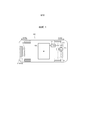
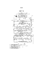
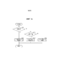
Фиг. 1 - схема, показывающая схематическую конфигурацию транспортного средства, оборудованного системой управления температурой в транспортном средстве, согласно варианту осуществления;FIG. 1 is a diagram showing a schematic configuration of a vehicle equipped with a vehicle temperature control system according to an embodiment;
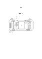
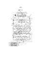
Фиг. 2 - схема, показывающая схематическую конфигурацию другого транспортного средства, оборудованного системой управления температурой в транспортном средстве согласно варианту осуществления;FIG. 2 is a diagram showing a schematic configuration of another vehicle equipped with a vehicle temperature control system according to an embodiment;
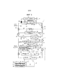
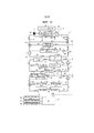
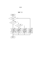
Фиг. 3 - схема конфигурации, схематически показывающая систему управления температурой в транспортном средстве согласно варианту осуществления;FIG. 3 is a configuration diagram schematically showing a temperature control system in a vehicle according to an embodiment;
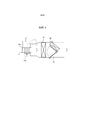
Фиг. 4 - схема конфигурации, схематично показывающая воздушный канал для кондиционирования воздуха транспортного средства, оборудованного системой управления температурой в транспортном средстве;FIG. 4 is a configuration diagram schematically showing an air duct for air conditioning a vehicle equipped with a vehicle temperature control system;
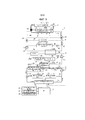
Фиг. 5 – иллюстрация состояния распределения (первый режим останова) теплоносителя в системе управления температурой в транспортном средстве, когда не требуется ни охлаждение, ни обогрев салона транспортного средства, и требуется охлаждение устройства, генерирующего тепло, такого как аккумуляторная батарея;FIG. 5 is an illustration of the distribution state (first stop mode) of the coolant in the vehicle temperature control system when neither cooling nor heating of the vehicle interior is required and cooling of a heat generating device such as a battery is required;
Фиг. 6 - иллюстрация состояния распределения (второй режим останова) теплоносителя в системе управления температурой транспортного средства, когда не требуется ни охлаждение, ни обогрев салона транспортного средства и требуется быстрое охлаждение тепловыделяющего устройства;FIG. 6 is an illustration of the distribution state (second stop mode) of the coolant in the vehicle temperature control system when neither cooling nor heating of the vehicle interior is required and rapid cooling of the fuel generating device is required;
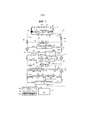
Фиг. 7 - иллюстрация состояния распределения (первый режим охлаждения) теплоносителя в системе управления температурой в транспортном средстве, когда требуется охлаждение салона транспортного средства и требуется охлаждение тепловыделяющего устройства;FIG. 7 is an illustration of the distribution state (first cooling mode) of the coolant in the vehicle temperature control system when cooling of the vehicle interior is required and cooling of the heat generating device is required;
Фиг. 8 - иллюстрация состояния распределения (второй режим охлаждения) теплоносителя в системе управления температурой транспортного средства, когда требуется охлаждение салона транспортного средства и требуется быстрое охлаждение тепловыделяющего устройства;FIG. 8 is an illustration of the distribution state (second cooling mode) of the coolant in the vehicle temperature control system when cooling of the vehicle interior is required and rapid cooling of the fuel generating device is required;
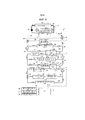
Фиг. 9 - иллюстрация состояния распределения (первый режим нагрева) теплоносителя в системе регулирования температуры транспортного средства, когда запрашивается обогрев салона транспортного средства и работает двигатель внутреннего сгорания;FIG. 9 is an illustration of the distribution state (first heating mode) of the heat medium in the vehicle temperature control system when heating of the vehicle interior is requested and the internal combustion engine is operating;
Фиг. 10 - иллюстрация состояния распределения (четвертый режим нагрева) теплоносителя в системе управления температурой в транспортном средстве, когда запрашивается обогрев салона транспортного средства и двигатель внутреннего сгорания остановлен;FIG. 10 is an illustration of the distribution state (fourth heating mode) of the heat medium in the vehicle temperature control system when heating of the vehicle interior is requested and the internal combustion engine is stopped;
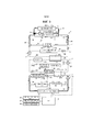
Фиг. 11 - иллюстрация состояния распределения (третий режим нагрева) теплоносителя в системе управления температурой транспортного средства во время холодного запуска двигателя внутреннего сгорания;FIG. 11 is an illustration of a distribution state (third heating mode) of a coolant in a vehicle temperature control system during a cold start of an internal combustion engine;
Фиг. 12 - иллюстрация состояния распределения (второй режим нагрева) теплоносителя в системе управления температурой в транспортном средстве во время холодного запуска двигателя внутреннего сгорания;FIG. 12 is an illustration of a distribution state (second heating mode) of a coolant in a temperature control system in a vehicle during a cold start of an internal combustion engine;
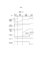
Фиг. 13 - временная диаграмма, показывающая изменения различных параметров, когда двигатель внутреннего сгорания запускается из холодного состояния в состоянии, когда требуется обогрев салона транспортного средства;FIG. 13 is a timing chart showing changes in various parameters when the internal combustion engine is started from a cold state in a state where heating of the vehicle interior is required;
Фиг. 14 - блок-схема программы управления, которая управляет состоянием распределения теплоносителя в системе управления температурой транспортного средства; иFIG. 14 is a flowchart of a control program that controls a state of distribution of a coolant in a vehicle temperature control system; and
Фиг. 15 - блок-схема, показывающая программу управления для управления нагревом, выполняемую на этапе S12 с фиг. 14.FIG. 15 is a flowchart showing a control program for heating control executed in step S12 of FIG. fourteen.
Подробное описание вариантов осуществления изобретенияDETAILED DESCRIPTION OF EMBODIMENTS OF THE INVENTION
[0019] Вариант осуществления настоящего изобретения будет подробно описан далее со ссылкой на чертежи. В последующем описании аналогичным компонентам присвоены одинаковые ссылочные позиции.[0019] An embodiment of the present invention will be described in detail below with reference to the drawings. In the following description, like reference numbers are assigned to like components.
Конфигурация транспортного средства Vehicle configuration
[0020] Фиг. 1 представляет собой схему, показывающую схематическую конфигурацию транспортного средства 100, оборудованного системой 1 управления температурой в транспортном средстве согласно варианту осуществления изобретения. На фиг. 1 левая сторона показывает переднюю часть транспортного средства 100, а правая сторона показывает заднюю часть транспортного средства 100. Как показано на фиг. 1, транспортное средство 100 включает в себя двигатель 110 внутреннего сгорания, мотор-генератор (MG) 112 и устройство 116 разделения мощности. Кроме того, транспортное средство 100 включает в себя блок 118 управления мощностью (PCU), электрически подключенный к MG 112, и аккумуляторную батарею 120, электрически подключенную к PCU 118.[0020] FIG. 1 is a diagram showing a schematic configuration of a
[0021] Двигатель 110 внутреннего сгорания является основным двигателем, который сжигает топливо внутри двигателя и преобразует тепловую энергию газа сгорания в механическую энергию. Двигатель 110 внутреннего сгорания подключен к устройству 116 разделения мощности, и выходная мощность двигателя 110 внутреннего сгорания используется для приведения в движение транспортного средства 100 или генерирования электроэнергии с использованием MG 112.[0021] The
[0022] MG 112 функционирует как электродвигатель и электрогенератор. MG 112 подключен к устройству 116 разделения мощности и используется для приведения в движение транспортного средства 100 и для рекуперации энергии при торможении транспортного средства 100. В настоящем варианте осуществления MG 112, имеющий функцию выработки мощности, используется в качестве мотора для приведения в движение транспортного средства 100, но вместо этого может использоваться мотор, не имеющий функции электрогенерирования.[0022] MG 112 functions as an electric motor and an electric generator. MG 112 is connected to a
[0023] PCU 118 подключен между аккумуляторной батареей 120 и MG 112 для управления электрической мощностью, подаваемой в MG 112. PCU 118 включает в себя компоненты, вырабатывающие тепло, такие как инвертор для приведения в действие мотора, повышающий преобразователь для управления напряжением и преобразователь постоянного тока в постоянный (DC-DC) для понижения высокого напряжения. Аккумуляторная батарея 120 соединена с PCU 118 и MG 112 для подачи в MG 112 электроэнергии для приведения в действие транспортного средства 100.[0023] PCU 118 is connected between
[0024] В настоящем варианте осуществления двигатель 110 внутреннего сгорания, MG 112 и PCU 118 расположены в задней части транспортного средства 100, то есть дальше в направлении назад от салона транспортного средства. С другой стороны, аккумуляторная батарея 120 расположена в центре транспортного средства 100, то есть под салоном транспортного средства.[0024] In the present embodiment, the
[0025] Транспортное средство 100 может быть любым типом транспортного средства, если оно включает в себя двигатель 110 внутреннего сгорания и MG (или мотор) 112. Поэтому, например, транспортное средство 100 может быть сконфигурировано так, что двигатель внутреннего сгорания используется только для выработки энергии, и только мотор приводит в движение транспортное средство 100.[0025]
[0026] В качестве конкретной конфигурации, в которой двигатель внутреннего сгорания используется только для выработки энергии, и только мотор приводит в движение транспортное средство 100, может применяться, например, транспортное средство 100’, показанное на фиг. 2. Как показано на фиг. 2, транспортное средство 100’ включает в себя двигатель 110 внутреннего сгорания, два MG 112a и 112b, два PCU 118a и 118b и аккумуляторную батарею 120.[0026] As a specific configuration in which the internal combustion engine is used only for power generation and only the motor drives the
[0027] Второй MG 112b приводится в действие движущей силой двигателя 110 внутреннего сгорания для выработки электроэнергии. Электроэнергия, генерируемая вторым MG 112b, подается в аккумуляторную батарею 120 и сохраняется в аккумуляторной батарее 120 или подается в первый MG 112a. Электроэнергия подается в первый MG 112a от аккумуляторной батареи 120 или второго MG 112b для приведения в движение транспортного средства 100. Первый MG 112a используется в качестве генератора энергии при выработке электроэнергии посредством рекуперации, а второй MG 112b используется в качестве электромотора (мотора) при запуске двигателя 110 внутреннего сгорания.[0027] The
Конфигурация системы управления температурой в транспортном средстве Vehicle Temperature Management System Configuration
[0028] Конфигурация системы 1 управления температурой в транспортном средстве согласно варианту осуществления будет описана со ссылкой на фиг. 1-4. Фиг. 3 представляет собой схему конфигурации, схематически показывающую систему 1 управления температурой в транспортном средстве. Система 1 управления температурой в транспортном средстве включает в себя контур 2 охлаждения, низкотемпературный контур 3, высокотемпературный контур 4 и устройство 6 управления. Охлаждающий контур 2, низкотемпературный контур 3 и высокотемпературный контур 4 функционируют как тепловые контуры, которые обмениваются теплом с внешним контуром.[0028] The configuration of the vehicle
Охлаждающий контурCooling circuit
[0029] Сначала будет описан охлаждающий контур 2. Охлаждающий контур 2 включает в себя компрессор 21, трубопровод 22а хладагента конденсатора 22, ресивер 23, первый расширительный клапан 24, второй расширительный клапан 25, испаритель 26, трубопровод 27а хладагента охладителя 27, первый электромагнитный регулирующий клапан 28 и второй электромагнитный регулирующий клапан 29. Охлаждающий контур 2 выполнен с возможностью реализации охлаждающего цикла посредством циркуляции хладагента через эти компоненты. В качестве хладагента используется любое вещество, обычно используемое в качестве хладагента в охлаждающем цикле, такое как гидрофторуглерод (например, HFC-134a).[0029] First, the
[0030] Охлаждающий контур 2 разделен на основной канал 2а охлаждающего потока, канал 2b потока испарителя и канал 2c потока охладителя. Канал 2b потока испарителя и канал 2c потока охладителя предусмотрены параллельно друг другу и соединены с основным каналом 2a охлаждающего потока.[0030] The
[0031] В основном канале 2а охлаждающего потока компрессор 21, трубопровод 22а хладагента конденсатора 22 и ресивер 23 предусмотрены в этом порядке в направлении циркуляции хладагента. В канале 2b потока испарителя первый электромагнитный регулирующий клапан 28, первый расширительный клапан 24 и испаритель 26 расположены в указанном порядке в направлении циркуляции хладагента. Кроме того, в канале 2c потока охладителя второй электромагнитный регулирующий клапан 29, второй расширительный клапан 25 и трубопровод 27a хладагента охладителя 27 предусмотрены в этом порядке.[0031] In the main
[0032] Компрессор 21 функционирует как компрессор, который сжимает хладагент. В настоящем варианте осуществления компрессор 21 представляет собой электрический компрессор и сконфигурирован таким образом, что его производительность по разряду может плавно изменяться каналом регулирования электрической мощности, подаваемой на компрессор 21. В компрессоре 21 низкотемпературный, в основном газообразный хладагент низкого давления, вытекающий из испарителя 26 или охладителя 27, может быть заменен на высокотемпературный, в основном газообразный хладагент высокого давления каналом адиабатического сжатия.[0032]
[0033] Конденсатор 22 включает в себя трубопровод 22a хладагента и трубопровод 22b хладагента. Конденсатор 22 функционирует как теплообменник, который отводит тепло от хладагента трубопровода 22a к хладагенту, протекающему через трубу 22b хладагента высокотемпературного контура 4, описанного далее, для конденсации хладагента. С другой точки зрения, конденсатор 22 функционирует как второй нагревательный блок, который нагревает хладагент высокотемпературного контура 4, используя тепло, отличное от тепла выхлопных газов двигателя 110 внутреннего сгорания. Трубопровод 22а хладагента конденсатора 22 функционирует как конденсатор, который конденсирует хладагент в охлаждающем цикле. Кроме того, в трубопроводе 22a хладагента конденсатора 22 высокотемпературный, в основном газообразный хладагент высокого давления, вытекающий из компрессора 21, может быть изменен на высокотемпературный, в основном жидкий хладагент высокого давления каналом изобарного охлаждения.[0033] The
[0034] Ресивер 23 хранит хладагент, сконденсированный трубопроводом 22а хладагента конденсатора 22. Кроме того, поскольку конденсатор 22 не может обязательно сжижать весь хладагент, ресивер 23 выполнен с возможностью разделения газа и жидкости. Из ресивера 23 выходит только жидкий хладагент, от которого отделяется газообразный хладагент.[0034] The
[0035] Первый расширительный клапан 24 и второй расширительный клапан 25 функционируют как расширители для расширения хладагента. Каждый из расширительных клапанов 24 и 25 имеет канал малого диаметра, и за счет распыления хладагента из канала малого диаметра давление хладагента резко снижается. Первый расширительный клапан 24 распыляет жидкий хладагент, подаваемый из ресивера 23, в испаритель 26 в виде тумана. Точно так же второй расширительный клапан 25 распыляет жидкий хладагент, подаваемый из ресивера 23, в трубопровод 27a хладагента охладителя 27 в виде тумана. В этих расширительных клапанах 24 и 25 высокотемпературный жидкий хладагент высокого давления, вытекающий из ресивера 23, может быть заменен на низкотемпературный, похожий на туман хладагент низкого давления каналом сброса давления и частичной газификации.[0035] The
[0036] Испаритель 26 функционирует как испаритель, испаряющий хладагент. В частности, испаритель 26 заставляет хладагент поглощать тепло из воздуха вокруг испарителя 26 для испарения хладагента. Таким образом, в испарителе 26 низкотемпературный, туманный хладагент низкого давления, вытекающий из первого расширительного клапана 24, может быть заменен на низкотемпературный газообразный хладагент низкого давления каналом испарения. В результате воздух вокруг испарителя 26 охлаждается, и может охлаждаться салон транспортного средства.[0036]
[0037] Охладитель 27 включает в себя трубопровод 27a хладагента и трубопровод 27b хладагента. Охладитель 27 функционирует как теплообменник, который заставляет хладагент поглощать тепло от хладагента, протекающего через трубу 27b хладагента низкотемпературного контура 3, описанного ниже, и испаряет хладагент. Трубопровод 27a хладагента охладителя 27 функционирует как испаритель, который испаряет хладагент. Таким образом, в трубопроводе 27a хладагента охладителя 27 низкотемпературный, похожий на туман хладагент низкого давления, вытекающий из второго расширительного клапана 25, может быть заменен на низкотемпературный газообразный хладагент низкого давления каналом испарения. В результате может охлаждаться хладагент низкотемпературного контура 3.[0037] The cooler 27 includes a
[0038] Первый электромагнитный регулирующий клапан 28 и второй электромагнитный регулирующий клапан 29 используются для изменения режима распределения хладагента в охлаждающем контуре 2. По мере того как степень открытия первого электромагнитного регулирующего клапана 28 увеличивается, количество хладагента, протекающего в канал 2b потока испарителя, увеличивается, и, таким образом, увеличивается количество хладагента, протекающего в испаритель 26. Кроме того, по мере того, как степень открытия второго электромагнитного регулирующего клапана 29 увеличивается, увеличивается количество хладагента, протекающего в канал 2c потока охладителя, и, таким образом, увеличивается количество хладагента, протекающего в охладитель 27. Вместо электромагнитных регулирующих клапанов 28 и 29 может быть предусмотрен любой клапан при условии, что скорости потоков, текущих из основного канала 2а охлаждающего потока в канал 2b потока испарителя и канал 2c потока охладителя, могут регулироваться.[0038] The
[0039] Как показано на фиг. 3, в настоящем варианте осуществления охлаждающий контур 2 расположен в передней части транспортного средства 100, то есть дальше в направлении вперед от пассажирского салона транспортного средства 100.[0039] As shown in FIG. 3, in the present embodiment, the
Низкотемпературный контурLow temperature circuit
[0040] Далее будет описан низкотемпературный контур 3. Низкотемпературный контур 3 включает в себя первый насос 31, трубопровод 27b хладагента охладителя 27, низкотемпературный радиатор 32, первый трехходовой клапан 33 и второй трехходовой клапан 34. Кроме того, низкотемпературный контур 3 включает в себя теплообменник 35 аккумуляторной батареи, теплообменник 36 PCU и теплообменник 37 MG. В низкотемпературном контуре 3 хладагент циркулирует через эти компоненты. Хладагент является примером второго теплоносителя, и в низкотемпературном контуре 3 может использоваться любой другой теплоноситель вместо хладагента.[0040] Next, the low-
[0041] Низкотемпературный контур 3 разделен на основной канал 3a низкотемпературного потока, канал 3b потока низкотемпературного радиатора и канал 3c потока тепловыделяющего устройства. Канал 3b потока низкотемпературного радиатора и канал 3c потока тепловыделяющего устройства расположены параллельно друг другу и соединены с основным каналом 3a низкотемпературного потока.[0041] The low-
[0042] В основном канале 3a низкотемпературного потока первый насос 31, трубопровод 27b хладагента охладителя 27 и теплообменник 35 аккумуляторной батареи расположены в этом порядке в направлении циркуляции хладагента. Кроме того, обходной канал 3d потока аккумуляторной батареи, предусмотренный для обхода теплообменника 35 аккумуляторной батареи, соединен с основным каналом 3a низкотемпературного потока. Первый трехходовой клапан 33 предусмотрен на участке соединения между основным каналом 3а низкотемпературного потока и обходным каналом 3d потока аккумуляторной батареи.[0042] In the main low-temperature flow path 3a, the
[0043] Кроме того, низкотемпературный радиатор 32 предусмотрен в канале 3b потока низкотемпературного радиатора. Теплообменник 36 PCU и теплообменник 37 MG предусмотрены в этом порядке на канале 3c потока тепловыделяющего устройства в направлении циркуляции хладагента. Теплообменник, который обменивается теплом с тепловыделяющим устройством, отличным от MG или PCU, может быть предусмотрен на канале 3c потока тепловыделяющего устройства. Второй трехходовой клапан 34 предусмотрен между основным каналом 3а низкотемпературного потока, каналом 3b низкотемпературного потока радиатора и каналом 3с потока тепловыделяющего устройства.[0043] In addition, a low-
[0044] Первый насос 31 перекачивает хладагент, циркулирующий в низкотемпературном контуре 3. В настоящем варианте осуществления первый насос 31 представляет собой электрический водяной насос и сконфигурирован таким образом, что его пропускная способность может плавно изменяться каналом регулирования электрической мощности, подаваемой на первый насос 31.[0044] The
[0045] Низкотемпературный радиатор 32 представляет собой теплообменник, который обменивается теплом между хладагентом, циркулирующим в низкотемпературном контуре 3, и воздухом вне транспортного средства 100 (наружным воздухом). Низкотемпературный радиатор 32 выполнен с возможностью отвода тепла от хладагента в наружный воздух, когда температура хладагента выше, чем температура наружного воздуха, и поглощения тепла из внешнего воздуха хладагенту, когда температура хладагента ниже температуры наружного воздуха.[0045] The
[0046] Первый трехходовой клапан 33 сконфигурирован таким образом, что хладагент, вытекающий из трубопровода 27b хладагента охладителя 27, избирательно протекает между теплообменником 35 аккумуляторной батареи и обходным каналом 3d потока аккумуляторной батареи. Второй трехходовой клапан 34 сконфигурирован так, что хладагент, вытекающий из основного канала 3а низкотемпературного потока, избирательно протекает между каналом 3b потока низкотемпературного радиатора и каналом 3с потока тепловыделяющего устройства.[0046] The first three-
[0047] До тех пор, пока скорость потока хладагента, протекающего в теплообменник 35 аккумуляторной батареи и обходной канал 3d аккумуляторной батареи, можно регулировать надлежащим образом, можно использовать другие регулирующие устройства, такие как регулирующий клапан и двухпозиционный клапан вместо первого трехходового клапана 33. Аналогичным образом, до тех пор, пока скорость потока хладагента, втекающего в канал 3b потока низкотемпературного радиатора и канал 3c потока тепловыделяющего устройства, можно регулировать надлежащим образом, вместо второго трехходового клапана 34 можно использовать другие регулирующие устройства, такие как регулирующий клапан и двухпозиционный клапан.[0047] As long as the flow rate of the refrigerant flowing to the
[0048] Теплообменник 35 аккумуляторной батареи выполнен с возможностью обмена теплом с аккумуляторной батареей 120 транспортного средства 100. В частности, теплообменник 35 аккумуляторной батареи включает в себя, например, трубопровод, предусмотренный вокруг аккумуляторной батареи 120, и сконфигурирован так, что теплообмен осуществляется между хладагентом, протекающим через трубопровод, и аккумуляторной батареей.[0048] The
[0049] Теплообменник 36 PCU выполнен с возможностью обмена теплом с PCU 118 транспортного средства 100. В частности, теплообменник 36 PCU включает в себя трубопровод, предусмотренный вокруг PCU 118, и сконфигурирован таким образом, что теплообмен осуществляется между хладагентом, протекающим по трубопроводу, и PCU. Кроме того, теплообменник 37 MG сконфигурирован для обмена теплом с MG 112 транспортного средства 100. В частности, теплообменник 37 MG сконфигурирован таким образом, что теплообмен осуществляется между маслом, текущим вокруг MG 112, и хладагентом.[0049] The
[0050] В настоящем варианте осуществления, поскольку MG 112 и PCU 118 расположены в задней части транспортного средства, как показано на фиг. 3, теплообменник 36 PCU и теплообменник 37 MG расположены в задней части транспортного средства, то есть дальше в направлении назад от салона транспортного средства 100 транспортного средства. С другой стороны, охладитель 27, первый насос 31, низкотемпературный радиатор 32, первый трехходовой клапан 33 и второй трехходовой клапан 34 расположены в передней части транспортного средства, то есть дальше в направлении вперед от салона транспортного средства. Кроме того, в настоящем варианте осуществления, поскольку аккумуляторная батарея 120 расположена под салоном транспортного средства, теплообменник 35 аккумуляторной батареи расположен в центре транспортного средства 100, то есть под салоном транспортного средства. Аккумуляторная батарея 120 может быть расположена в месте, отличном от салона транспортного средства, и поэтому теплообменник 35 аккумуляторной батареи может быть расположен в месте, отличном от места под салоном транспортного средства.[0050] In the present embodiment, since
Высокотемпературный контурHigh temperature circuit
[0051] Далее будет описан высокотемпературный контур 4. Высокотемпературный контур 4 включает в себя второй насос 41, трубопровод 22b хладагента конденсатора 22, высокотемпературный радиатор 42, сердечник 43 нагревателя, третий трехходовой клапан 44, четвертый трехходовой клапан 45, третий электромагнитный регулирующий клапан 46, четвертый электромагнитный регулирующий клапан 47 и контур 5 охлаждения двигателя. В высокотемпературном контуре 4 хладагент циркулирует через эти компоненты. Хладагент является примером первого теплоносителя, и любой другой теплоноситель может использоваться вместо хладагента в высокотемпературном контуре 4.[0051] Next, the
[0052] Высокотемпературный контур 4 разделен на основной канал 4a высокотемпературного потока, канал 4b высокотемпературного радиатора, канал 4c нагревателя, канал 4d входящего потока двигателя, канал 4e выходящего потока двигателя и обходной канал 4f потока сердечника. В основном канале 4a высокотемпературного потока второй насос 41 и трубопровод 22b хладагента конденсатора 22 предусмотрены в этом порядке в направлении циркуляции хладагента. В канале 4b потока высокотемпературного радиатора третий электромагнитный регулирующий клапан 46 и высокотемпературный радиатор 42 предусмотрены в этом порядке в направлении циркуляции хладагента. Кроме того, в канале 4с потока нагревателя предусмотрен четвертый электромагнитный регулирующий клапан 47 и сердечник 43 нагревателя в направлении циркуляции хладагента. Электрический нагреватель может быть предусмотрен в канале 4c потока нагревателя на стороне входа сердечника 43 нагревателя в направлении циркуляции хладагента. Контур 5 охлаждения двигателя предусмотрен между каналом 4d входящего потока двигателя и каналом 4e выходящего потока двигателя.[0052] The
[0053] Канал 4b потока высокотемпературного радиатора и канал 4с потока нагревателя расположены параллельно друг другу и соединены с основным каналом 4a высокотемпературного потока. Таким образом, сердечник 43 нагревателя и высокотемпературный радиатор 42 предусмотрены параллельно второму нагревательному блоку.[0053] The high-temperature
[0054] Канал 4d входящего потока двигателя обеспечивает сообщение канала 4c потока нагревателя с контуром 5 охлаждения двигателя. В частности, канал 4d входящего потока двигателя соединяет канал 4c потока нагревателя на выходной стороне сердечника 43 нагревателя в направлении циркуляции хладагента и контур 5 охлаждения двигателя на входной стороне теплообменника 52 двигателя в направлении циркуляции хладагента в контуре охлаждения двигателя 5.[0054] The
[0055] Канал 4e выходящего потока двигателя также обеспечивает сообщение канала 4с потока нагревателя с контуром 5 охлаждения двигателя. В частности, канал 4e выходящего потока двигателя соединяет канал 4c потока нагревателя на стороне входа сердечника 43 нагревателя в направлении циркуляции хладагента и контур 5 охлаждения двигателя на стороне выхода теплообменника 52 двигателя в направлении циркуляции хладагента в контуре охлаждения двигателя 5.[0055] The
[0056] Обходной канал 4f потока сердечника сообщается с каналом 4d входящего потока двигателя и каналом 4e выходящего потока двигателя. Таким образом, хладагент, вытекающий из контура 5 охлаждения двигателя, может протекать через обходной канал 4f потока сердечника и возвращаться в контур 5 охлаждения двигателя, не протекая через сердечник 43 нагревателя. Другими словами, обходной канал 4f потока сердечника функционирует как канал потока, который обходит сердечник 43 нагревателя. Обходной канал 4f потока сердечника может быть расположен так, чтобы сообщаться с каналом 4c потока нагревателя на стороне входа и стороне выхода сердечника 43 нагревателя, пока сердечник 43 нагревателя может быть обойден потоком.[0056] The
[0057] Кроме того, третий трехходовой клапан 44 предусмотрен между каналом 4e выходящего потока двигателя и обходным каналом 4f потока сердечника. Третий трехходовой клапан 44 может быть предусмотрен между каналом 4d входящего потока двигателя и обходным каналом 4f основного потока. Кроме того, четвертый трехходовой клапан 45 предусмотрен между каналом 4с потока нагревателя и каналом 4d входящего потока двигателя. Четвертый трехходовой клапан 45 может быть предусмотрен между каналом 4e выходящего потока двигателя и каналом 4с потока нагревателя.[0057] In addition, a third three-
[0058] С другой точки зрения, высокотемпературный контур 4 можно рассматривать как имеющий два тепловых контура: первый высокотемпературный контур и второй высокотемпературный контур, которые совместно используют канал 4c потока нагревателя. Из них первый высокотемпературный контур имеет канал 4c потока нагревателя, канал 4d входящего потока двигателя, контур 5 охлаждения двигателя, канал 4e выходящего потока двигателя и обходной канал 4f потока сердечника. Таким образом, в первом высокотемпературном контуре хладагент может циркулировать между контуром 5 охлаждения двигателя (в частности, теплообменником 52 двигателя) и сердечником 43 нагревателя, а также между контуром 5 охлаждения двигателя и обходным контуром 4f потока сердечника. С другой стороны, второй высокотемпературный контур имеет канал 4c потока нагревателя, основной канал 4a высокотемпературного потока и канал 4b потока высокотемпературного радиатора. Таким образом, во втором высокотемпературном контуре хладагент может циркулировать между трубопроводом 22b хладагента конденсатора 22 и сердечником 43 нагревателя.[0058] From another point of view, the
[0059] Второй насос 41 перекачивает хладагент, циркулирующий в высокотемпературном контуре 4. В настоящем варианте осуществления второй насос 41 представляет собой электрический водяной насос, аналогичный первому насосу 31. Кроме того, высокотемпературный радиатор 42 является теплообменником, который обменивается теплом между хладагентом, циркулирующим в высокотемпературном контуре 4, и наружным воздухом, аналогично низкотемпературному радиатору 32.[0059] The
[0060] Сердечник 43 обогревателя используется для обогрева салона транспортного средства с использованием тепла хладагента в высокотемпературном контуре 4. То есть сердечник 43 нагревателя выполнен с возможностью обмена теплом между хладагентом, циркулирующим в высокотемпературном контуре 4, и воздухом вокруг сердечника 43 нагревателя, чтобы нагреть воздух вокруг сердечника 43 нагревателя и, как результат, обогреть салон транспортного средства. В частности, сердечник 43 нагревателя выполнен с возможностью отвода тепла от хладагента в воздух вокруг сердечника 43 нагревателя. Следовательно, когда высокотемпературный хладагент протекает через сердечник 43 нагревателя, температура хладагента уменьшается, и воздух вокруг сердечника 43 нагревателя нагревается.[0060] The
[0061] Третий трехходовой клапан 44 функционирует как первое устройство переключения режима сообщения, которое может переключаться между первым состоянием сообщения, в котором канал 4e выходящего потока двигателя сообщается с каналом 4c потока нагревателя, вторым состоянием сообщения, в котором канал 4e выходящего потока двигателя сообщается с обходным каналом 4f потока сердечника, и третьим состоянием сообщения, в котором канал 4e выходящего потока двигателя не сообщается ни с каналом 4c потока нагревателя, ни с обходным каналом 4f потока сердечника. Другими словами, третий трехходовой клапан 44 функционирует как механизм переключения состояний распределения для переключения состояний распределения теплоносителя в высокотемпературном контуре 4. Когда третий трехходовой клапан 44 установлен в первое состояние сообщения, хладагент, вытекающий из контура 5 охлаждения двигателя, течет в канал 4c потока нагревателя на стороне входа сердечника 43 нагревателя через канал 4e выходящего потока двигателя. Когда третий трехходовой клапан 44 установлен во второе состояние сообщения, хладагент, вытекающий из контура 5 охлаждения двигателя, течет в обходной канал 4f потока сердечника через канал 4e выходящего потока двигателя. Когда третий трехходовой клапан 44 установлен в третье состояние сообщения, хладагент в контуре 5 охлаждения двигателя не течет в канал 4e выходящего потока двигателя и, таким образом, циркулирует внутри контура 5 охлаждения двигателя. До тех пор, пока расход хладагента, текущего из контура 5 охлаждения двигателя в канал 4c нагревателя и обходной канал 4f сердечника, можно регулировать надлежащим образом, другие устройства управления режимом распределения, такие как регулирующий клапан и двухпозиционный клапан может использоваться вместо третьего трехходового клапана 44.[0061] The third three-
[0062] Четвертый трехходовой клапан 45 функционирует как второе устройство переключения режима сообщения, которое может переключаться между первым состоянием сообщения, в котором канал 4c потока нагревателя сообщается с высокотемпературным контуром 4, и вторым состоянием сообщения, в котором канал 4c потока нагревателя сообщается с каналом 4d входящего потока двигателя. Другими словами, четвертый трехходовой клапан 45 функционирует как механизм переключения состояния распределения для переключения состояний распределения теплоносителя в высокотемпературном контуре 4. Когда четвертый трехходовой клапан 45 установлен в первое состояние сообщения, хладагент, вытекающий из сердечника 43 нагревателя, течет во второй насос 41 через канал 4c потока нагревателя. С другой стороны, когда четвертый трехходовой клапан 45 установлен во второе состояние сообщения, хладагент, вытекающий из сердечника 43 нагревателя, течет в контур 5 охлаждения двигателя через канал 4d входящего потока двигателя. Для регулирования расхода хладагента, протекающего из сердечника 43 нагревателя во второй насос 41 и контур 5 охлаждения двигателя, надлежащим образом, можно использовать другие устройства управления режимом распределения, такие как регулирующий клапан и двухпозиционный клапан вместо четвертого трехходового клапана 45.[0062] The fourth three-
[0063] Третий электромагнитный регулирующий клапан 46 и четвертый электромагнитный регулирующий клапан 47 используются в качестве устройств управления третьим режимом распределения, которые управляют режимом распределения хладагента в высокотемпературном контуре 4 и, в частности, режимом распределения хладагента из трубопровода 22b хладагента конденсатора 22 к высокотемпературному радиатору 42 и сердечнику 43 нагревателя. По мере того как степень открытия третьего электромагнитного регулирующего клапана 46 увеличивается, количество хладагента, протекающего в канал 4b потока высокотемпературного радиатора, увеличивается, и, таким образом, увеличивается количество хладагента, протекающего в высокотемпературный радиатор 42. Кроме того, по мере увеличения степени открытия четвертого электромагнитного регулирующего клапана 47 количество хладагента, протекающего в проточный канал 4c нагревателя, увеличивается, и, таким образом, увеличивается количество хладагента, протекающего в сердечник 43 нагревателя. В настоящем варианте осуществления электромагнитные регулирующие клапаны 46 и 47 сконфигурированы как клапаны, степень открытия которых можно регулировать, хотя они могут быть двухпозиционными клапанами, которые можно переключать между открытым состоянием и закрытым состоянием. Кроме того, вместо третьего электромагнитного регулирующего клапана 46 и четвертого электромагнитного регулирующего клапана 47 может быть предусмотрен трехходовой клапан, который позволяет хладагенту из основного канала 4а высокотемпературного потока избирательно течь только в канал 4b потока высокотемпературного радиатора, только канал 4c потока нагревателя и/или как канал 4b потока высокотемпературного радиатора, так и канал 4c потока нагревателя. Следовательно, любой клапан может быть предусмотрен в качестве устройства управления третьим режимом распределения вместо этих электромагнитных регулирующих клапанов 46 и 47, если можно отрегулировать скорость потока, текущего из основного канала 4a высокотемпературного потока в канал 4b высокотемпературного радиатора и канал 4c потока нагревателя.[0063] The third
[0064] Как показано на фиг. 3, в настоящем варианте осуществления контур 5 охлаждения двигателя расположен в задней части транспортного средства 100, то есть дальше в направлении назад от салона транспортного средства 100 транспортного средства. С другой стороны, компоненты (конденсатор 22, высокотемпературный радиатор 42, сердечник 43 нагревателя и т.д.) высокотемпературного контура 4, кроме контура 5 охлаждения двигателя, расположены в передней части транспортного средства 100, то есть дальше в направлении вперед от салона транспортного средства. Кроме того, основной обходной канал 4f потока также расположен дальше в направлении вперед салона транспортного средства. Следовательно, канал 4d входящего потока двигателя и канал 4e выходящего потока двигателя расположены так, чтобы проходить между передней и задней частью салона транспортного средства.[0064] As shown in FIG. 3, in the present embodiment, the
Контур охлаждения двигателяEngine cooling circuit
[0065] Далее будет описан контур 5 охлаждения двигателя. Контур 5 охлаждения двигателя включает в себя третий насос 51, теплообменник 52 двигателя, радиатор 53 двигателя и термостат 54. В контуре 5 охлаждения двигателя через эти компоненты циркулирует тот же хладагент, что и в высокотемпературном контуре 4.[0065] Next, the
[0066] Контур 5 охлаждения двигателя разделен на основной канал 5a потока двигателя, канал 5b потока радиатора двигателя и обходной канал 5c потока двигателя. Канал 5b потока радиатора двигателя и обходной канал 5c потока двигателя расположены параллельно друг другу и соединены с основным каналом 5a потока двигателя.[0066] The
[0067] В основном канале 5а потока двигателя третий насос 51 и теплообменник 52 двигателя предусмотрены в этом порядке в направлении циркуляции хладагента. Радиатор 53 двигателя предусмотрен в канале 5b потока радиатора двигателя. Кроме того, канал 4d входящего потока двигателя и канал 4e выходящего потока двигателя сообщаются с обходным каналом 5c потока двигателя. В частности, канал 4d входящего потока двигателя сообщается с расположенной ниже по потоку частью обходного канала 5c двигателя. В результате канал 4d входящего потока двигателя сообщается с окрестностью входа теплообменника 52 двигателя. С другой стороны, канал 4e выходящего потока двигателя сообщается с входной частью обходного канала 5c потока двигателя. В результате канал 4e выходящего потока двигателя сообщается с окрестностью выхода теплообменника 52 двигателя. Следовательно, теплообменник 52 двигателя выполнен с возможностью сообщения с высокотемпературным контуром 4 таким образом, что хладагент высокотемпературного контура 4 протекает через теплообменник 52 двигателя. Термостат 54 предусмотрен между основным каналом 5а потока двигателя и каналом 5b потока радиатора двигателя, а также между основным каналом 5а потока двигателя и обходным каналом 5с потока двигателя. В примере, показанном на фиг. 3, канал 4e выходящего потока двигателя сообщается с обходным каналом 5c потока двигателя, но может сообщаться с каналом 5b потока радиатора двигателя.[0067] In the
[0068] Третий насос 51 качает хладагент, циркулирующий в контуре 5 охлаждения двигателя. В настоящем варианте осуществления третий насос 51 представляет собой электрический водяной насос, аналогичный первому насосу 31. Кроме того, радиатор 53 двигателя представляет собой теплообменник, который обменивается теплом между хладагентом, циркулирующим в контуре 5 охлаждения двигателя, и наружным воздухом аналогично низкотемпературному радиатору 32.[0068] The
[0069] Теплообменник 52 двигателя функционирует как первый нагревательный блок, используемый для нагрева хладагента с использованием тепла выхлопных газов двигателя 110 внутреннего сгорания. То есть теплообменник 52 двигателя отводит тепло двигателя 110 внутреннего сгорания к хладагенту в контуре 5 охлаждения двигателя, чтобы нагреть хладагент. Теплообменник 52 двигателя препятствует чрезмерному повышению температуры двигателя 110 внутреннего сгорания за счет отвода тепла, генерируемого при сгорании топлива в двигателе 110 внутреннего сгорания, хладагенту. Теплообменник 52 двигателя имеет, например, канал для хладагента, предусмотренный в блоке цилиндров или головке цилиндров двигателя 110 внутреннего сгорания.[0069] The
[0070] Термостат 54 представляет собой клапан, который может переключаться между закрытым состоянием клапана, которое блокирует хладагент, протекающий через канал 5b потока радиатора двигателя, и открытым состоянием клапана, которое позволяет хладагенту проходить через канал 5b потока радиатора двигателя. Термостат 54 открывается так, что хладагент протекает через канал 5b потока радиатора двигателя, когда температура хладагента, циркулирующего через обходной канал 5c потока двигателя, равна или выше заданной температуры. С другой стороны, термостат 54 закрыт, так что хладагент не протекает через канал 5b потока радиатора двигателя, когда температура хладагента, циркулирующего через обходной канал 5c потока двигателя, ниже заданной температуры. В результате температура хладагента, протекающего через теплообменник 52 двигателя, сохраняется по существу постоянной.[0070]
Воздушный проходAir passage
[0071] Фиг. 4 представляет собой схему конфигурации, схематически показывающую воздушный канал 7 для кондиционирования воздуха транспортного средства 100, оборудованного системой 1 управления температурой в транспортном средстве. В воздушном канале 7 воздух течет в направлении, указанном стрелками на фиг. 4. Воздушный канал 7, показанный на фиг. 4 соединен с отверстием для всасывания воздуха за пределами транспортного средства 100 или в салоне транспортного средства, и наружный воздух или воздух из салона транспортного средства течет в воздушный канал 7 в зависимости от состояния управления устройством 6 управления. Кроме того, воздушный канал 7, показанный на фиг. 4, соединен с множеством отверстий для продувки воздуха для вдувания воздуха в салон транспортного средства, и воздух подается из воздушного канала 7 в любое из отверстий в зависимости от состояния управления устройством 6 управления.[0071] FIG. 4 is a configuration diagram schematically showing an
[0072] Как показано на фиг. 4, в воздушном канале 7 для кондиционирования воздуха согласно настоящему варианту осуществления нагнетатель 71, испаритель 26, дверца 72 смешивания воздуха и сердечник 43 нагревателя предусмотрены в этом порядке в направлении воздушного потока.[0072] As shown in FIG. 4, in the air
[0073] Нагнетатель 71 включает в себя нагнетательный электродвигатель 71а и нагнетательный вентилятор 71b. Нагнетатель 71 сконфигурирован так, что, когда нагнетательный вентилятор 71b приводится в действие нагнетательным электродвигателем 71а, наружный воздух или воздух в салоне транспортного средства течет в воздушный канал 7, и воздух проходит через воздушный канал 7.[0073] The
[0074] Дверца 72 смешивания воздуха регулирует расход воздуха, проходящего через сердечник 43 нагревателя, среди воздуха, проходящего через воздушный канал 7. Дверца 72 смешивания воздуха выполнена с возможностью регулирования между состоянием, в котором весь воздух, проходящий через воздушный канал 7, проходит через сердечник 43 нагревателя, состоянием, в котором весь воздух, проходящий через воздушный канал 7, не проходит через сердечник 43 нагревателя, и состоянием, в котором часть воздуха, проходящего через воздушный канал, проходит через сердечник 43 нагревателя.[0074] The
[0075] В воздушном канале 7, сконфигурированном таким образом, когда нагнетатель 71 приводится в действие и хладагент циркулирует в испарителе 26, охлаждается воздух, проходящий через воздушный канал 7. Кроме того, когда нагнетатель 71 приводится в действие, хладагент циркулирует в сердечнике 43 нагревателя, и дверца 72 смешивания воздуха регулируется так, что воздух проходит через сердечник 43 нагревателя, и воздух, проходящий через воздушный канал 7, нагревается.[0075] In the
[0076] Как показано на фиг. 1, низкотемпературный радиатор 32, высокотемпературный радиатор 42 и радиатор 53 двигателя расположены внутри передней решетки транспортного средства 100. Таким образом, когда транспортное средство 100 едет, радиаторы 32, 42 и 53 подвергаются воздействию ветра. Кроме того, рядом с этими радиаторами 32, 42, 53 предусмотрен вентилятор 76. Вентилятор 76 выполнен таким образом, что, когда вентилятор 76 приводится в действие, радиаторы 32, 42 и 53 подвергаются воздействию ветра. Таким образом, даже когда транспортное средство 100 не движется, радиаторы 32, 42 и 53 могут подвергаться воздействию ветра посредством приведения в действие вентилятора 76.[0076] As shown in FIG. 1, the
Устройство управленияControl device
[0077] Как показано на фиг. 3, устройство 6 управления включает в себя электронный блок 61 управления (ЭБУ). ЭБУ 61 включает в себя процессор, который выполняет различные вычисления, память, в которой хранятся программы и различные фрагменты информации, и интерфейс, который подключен к различным исполнительным механизмам и различным датчикам.[0077] As shown in FIG. 3, the
[0078] Кроме того, устройство 6 управления включает в себя первый датчик 62 температуры воды, который определяет температуру хладагента в контуре 5 охлаждения двигателя, в частности, температуру хладагента, протекающего через обходной канал 5c двигателя. Кроме того, устройство 6 управления включает в себя второй датчик 63 температуры воды, который определяет температуру хладагента, протекающего через канал 4e выходящего потока двигателя в передней части транспортного средства, или температуру хладагента, протекающего по каналу 4c потока нагревателя или обходному каналу 4f потока сердечника. ЭБУ 61 подключен к этим датчикам, и выходные сигналы от этих датчиков вводятся в ЭБУ 61.[0078] In addition, the
[0079] Кроме того, устройство 6 управления включает в себя датчик 66 температуры внутреннего пространства, который определяет температуру внутри транспортного средства 100, датчик 67 температуры наружного воздуха, который определяет температуру наружного воздуха транспортного средства 100, и панель 68 управления, которая приводится в действие пользователем. ЭБУ 61 подключен к этим датчикам и панели 68 управления, и выходные сигналы от этих датчиков и панели 68 управления вводятся в ЭБУ 61.[0079] In addition, the
[0080] ЭБУ 61 определяет, есть ли запрос на охлаждение или запрос на обогрев, на основе выходных сигналов от датчиков 66 и 67 и панели 68 управления. Например, когда пользователь включает переключатель нагрева на панели 68 управления, ЭБУ 61 определяет, что требуется нагрев. Кроме того, когда пользователь включает автоматический переключатель панели управления 68, например, когда температура внутри салона, установленная пользователем, ниже, чем температура, определенная датчиком 66 температуры внутри салона, ЭБУ 61 определяет, что требуется обогрев.[0080]
[0081] Кроме того, ЭБУ 61 соединен с различными исполнительными механизмами системы 1 управления температурой в транспортном средстве для управления этими исполнительными механизмами. В частности, ЭБУ 61 соединен с компрессором 21, электромагнитными регулирующими клапанами 28, 29, 46, 47, насосами 31, 41, 51, трехходовыми клапанами 33, 34, 44, 45, электродвигателем 71a нагнетателя, дверцей 72 смешивания воздуха и вентилятором 76 для управления этими компонентами. Следовательно, ЭБУ 61 функционирует как устройство управления, которое управляет механизмом переключения состояний распределения, который переключает состояние распределения теплоносителя (хладагента) в охлаждающем контуре 2, низкотемпературном контуре 3 и высокотемпературном контуре 4 (включая контур охлаждения двигателя 5).[0081] In addition,
Работа системы управления температурой в транспортном средстве Vehicle temperature control system operation
[0082] Далее состояние распределения типичного теплоносителя (хладагента) в системе 1 управления температурой в транспортном средстве будет описано со ссылкой на фиг. 5-10. На фиг. 5-10 каналы потока, через которые проходят потоки хладагентов, показаны сплошными линиями, а каналы потока, через которые хладагенты не проходят, показаны пунктирными линиями. Тонкие стрелки на чертежах указывают направление, в котором текут хладагенты, а толстые стрелки на чертеже указывают направление, в котором передается тепло.[0082] Next, a distribution state of a typical heat transfer medium (coolant) in the vehicle
[0083] На фиг.5 показано состояние распределения (первый режим останова) теплоносителя в системе 1 управления температурой в транспортном средстве, когда ни охлаждение, ни обогрев салона транспортного средства не запрашиваются и требуется охлаждение тепловыделяющего устройства, такого как аккумуляторная батарея.[0083] Fig. 5 shows the distribution state (first stop mode) of the coolant in the vehicle
[0084] Как показано на фиг. 5, в первом режиме останова работа компрессора 21 и второго насоса 41 останавливается. Таким образом, хладагент не циркулирует в охлаждающем контуре 2, и хладагент не циркулирует в высокотемпературном контуре 4. С другой стороны, в первом режиме останова работает первый насос 31. Таким образом, хладагент циркулирует в низкотемпературном контуре 3.[0084] As shown in FIG. 5, in the first stop mode, the operation of the
[0085] Кроме того, в первом режиме останова первый трехходовой клапан 33 установлен так, что хладагент протекает через теплообменник 35 аккумуляторной батареи. Кроме того, в примере, показанном на фиг. 5, второй трехходовой клапан 34 установлен так, что хладагент течет как через канал 3b потока низкотемпературного радиатора, так и канал 3c потока тепловыделяющего устройства. Первый трехходовой клапан 33 может быть настроен так, чтобы хладагент не проходил через теплообменник 35 аккумуляторной батареи в первом режиме останова.[0085] In addition, in the first stop mode, the first three-
[0086] В результате в первом режиме останова тепло аккумуляторной батареи, MG 112 и PCU 118 (тепловыделяющих устройств) передается хладагенту в теплообменнике 35 аккумуляторной батареи, теплообменнике 36 PCU и теплообменнике 37 MG (в дальнейшем вместе именуемые «теплообменники тепловыделяющих устройств»). Таким образом, тепловыделяющие устройства охлаждаются, и температура хладагента повышается до температуры, равной температуре наружного воздуха или выше. После этого хладагент охлаждается за счет обмена теплом с наружным воздухом в низкотемпературном радиаторе 32 и снова течет в теплообменники тепловыделяющих устройств. Следовательно, в первом режиме останова тепло от тепловыделяющих устройств поглощается теплообменниками тепловыделяющих устройств, и тепло отводится низкотемпературным радиатором 32.[0086] As a result, in the first shutdown mode, heat of the battery,
[0087] В примере, показанном на фиг. 5, в это время работает двигатель 110 внутреннего сгорания. Таким образом, работает третий насос 51, и третий трехходовой клапан 44 установлен в третье состояние сообщения, так что хладагент циркулирует в контуре 5 охлаждения двигателя. Когда температура хладагента в контуре 5 охлаждения двигателя высока, термостат 54 открывается, и хладагент также циркулирует в радиаторе 53 двигателя. Кроме того, когда двигатель 110 внутреннего сгорания остановлен, работа третьего насоса 51 останавливается, так что хладагент не циркулирует в контуре 5 охлаждения двигателя.[0087] In the example shown in FIG. 5, the
[0088] Фиг. 6 показано состояние распределения (второй режим останова) теплоносителя в системе 1 управления температурой в транспортном средстве, когда не требуется ни охлаждение, ни обогрев салона транспортного средства и требуется быстрое охлаждение тепловыделяющего устройства. Кроме того, в примере, показанном на фиг. 6, работает двигатель 110 внутреннего сгорания.[0088] FIG. 6 shows the distribution state (second stop mode) of the coolant in the vehicle
[0089] Как показано на фиг. 6, во втором режиме останова работают все из компрессора 21, первого насоса 31 и второго насоса 41. Следовательно, хладагенты циркулируют во всем охлаждающем контуре 2, низкотемпературном контуре 3 и высокотемпературном контуре 4.[0089] As shown in FIG. 6, in the second stop mode, all of the
[0090] Кроме того, во втором режиме останова первый электромагнитный регулирующий клапан 28 закрывается, а второй электромагнитный регулирующий клапан 29 открывается. Таким образом, хладагент не проходит через испаритель 26, и хладагент проходит через охладитель 27. Кроме того, во втором режиме останова первый трехходовой клапан 33 установлен так, что хладагент протекает через теплообменник 35 аккумуляторной батареи. Кроме того, в примере, показанном на фиг. 6, второй трехходовой клапан 34 установлен так, что хладагент протекает как через канал 3b потока низкотемпературного радиатора, так и через канал 3c потока тепловыделяющего устройства. В результате хладагент также протекает через теплообменник 36 PCU и теплообменник 37 MG, так что MG 112 и PCU 118 могут охлаждаться. Кроме того, во втором режиме останова открывается третий электромагнитный регулирующий клапан 46, а четвертый электромагнитный регулирующий клапан 47 закрывается. Следовательно, хладагент в высокотемпературном контуре 4 течет в канал 4b потока высокотемпературного радиатора после прохождения через конденсатор 22.[0090] In addition, in the second stop mode, the first
[0091] В результате во втором режиме останова тепло хладагента в низкотемпературном контуре 3 передается хладагенту в охладителе 27, и хладагент охлаждается. После этого низкотемпературный хладагент проходит через теплообменники тепловыделяющих устройств, таких как теплообменник 35 аккумуляторной батареи, и тепловыделяющие устройства охлаждаются. С другой стороны, тепло хладагента передается высокотемпературному контуру 4 в конденсаторе 22, и хладагент в высокотемпературном контуре 4 нагревается. После этого высокотемпературный хладагент охлаждается за счет обмена теплом с наружным воздухом в высокотемпературном радиаторе 42 и снова течет в конденсатор 22. Следовательно, во втором режиме останова тепло от тепловыделяющих устройств поглощается теплообменниками тепловыделяющих устройств, а тепло отводится высокотемпературным радиатором 42.[0091] As a result, in the second stop mode, the heat of the refrigerant in the
[0092] На фиг.7 показано состояние распределения (первый режим охлаждения) теплоносителя в системе 1 регулирования температуры в транспортном средстве, когда требуется охлаждение салона транспортного средства и требуется охлаждение тепловыделяющих устройств. В примере, показанном на фиг. 7, работает двигатель 110 внутреннего сгорания.[0092] Fig. 7 shows a distribution state (first cooling mode) of a coolant in the vehicle
[0093] Как показано на фиг. 7, в первом режиме охлаждения работают все из компрессора 21, первого насоса 31 и второго насоса 41. Кроме того, в первом режиме охлаждения первый электромагнитный регулирующий клапан 28 открыт, второй электромагнитный регулирующий клапан 29 закрыт, третий электромагнитный регулирующий клапан 46 открыт, и четвертый электромагнитный регулирующий клапан 47 закрыт. Кроме того, в примере, показанном на фиг. 7, второй трехходовой клапан 34 установлен так, что хладагент течет как через канал 3b потока низкотемпературного радиатора, так и канал 3c потока тепловыделяющего устройства.[0093] As shown in FIG. 7, in the first cooling mode, all of the
[0094] В результате в первом режиме охлаждения тепло окружающего воздуха передается хладагенту испарителем 26, и окружающий воздух охлаждается. С другой стороны, тепло хладагента передается высокотемпературному контуру 4 в конденсаторе 22, и хладагент в высокотемпературном контуре 4 нагревается. После этого высокотемпературный хладагент охлаждается за счет обмена теплом с наружным воздухом в высокотемпературном радиаторе 42 и снова течет в конденсатор 22. Следовательно, в первом режиме охлаждения испаритель 26 поглощает тепло из окружающего воздуха, а высокотемпературный радиатор 42 отводит тепло.[0094] As a result, in the first cooling mode, heat from the ambient air is transferred to the refrigerant by the
[0095] Кроме того, в первом режиме охлаждения тепло тепловыделяющих устройств передается хладагенту в теплообменниках тепловыделяющих устройств, а затем хладагент охлаждается посредством обмена теплом с наружным воздухом в низкотемпературном радиаторе 32 и снова течет в теплообменник 35 аккумуляторной батареи. Следовательно, тепло от тепловыделяющих устройств поглощается теплообменниками тепловыделяющих устройств, и тепло отводится низкотемпературным радиатором 32. [0095] In addition, in the first cooling mode, the heat of the heat generating devices is transferred to the refrigerant in the heat exchangers of the heat generating devices, and then the refrigerant is cooled by exchanging heat with outside air in the
[0096] На фиг. 8 показано состояние распределения (второй режим охлаждения) теплоносителя в системе 1 управления температурой в транспортном средстве, когда требуется охлаждение салона транспортного средства и требуется быстрое охлаждение тепловыделяющих устройств.[0096] FIG. 8 shows the distribution state (second cooling mode) of the coolant in the vehicle
[0097] Как показано на фиг. 8, во втором режиме охлаждения работают все из компрессора 21, первого насоса 31 и второго насоса 41. Кроме того, во втором режиме охлаждения как первый электромагнитный регулирующий клапан 28, так и второй электромагнитный регулирующий клапан 29 открываются, так что хладагент течет как через испаритель 26, так и через охладитель 27. Степени открытия электромагнитных регулирующих клапанов 28 и 29 в это время регулируются в зависимости от силы охлаждения, температуры аккумуляторной батареи и т.п. Кроме того, во втором режиме охлаждения первый трехходовой клапан 33 установлен так, что хладагент протекает через теплообменник 35 аккумуляторной батареи. Кроме того, в примере, показанном на фиг. 8, второй трехходовой клапан 34 установлен так, что хладагент течет как через канал 3b потока низкотемпературного радиатора, так и канал 3c потока тепловыделяющего устройства. Однако второй трехходовой клапан 34 может быть настроен так, что хладагент протекает только через канал 3b потока низкотемпературного радиатора. Кроме того, во втором режиме охлаждения третий электромагнитный регулирующий клапан 46 открывается, а четвертый электромагнитный регулирующий клапан 47 закрывается.[0097] As shown in FIG. 8, in the second refrigeration mode, all of the
[0098] В результате во втором режиме охлаждения тепло хладагента в низкотемпературном контуре 3 передается хладагенту в охладителе 27, и хладагент охлаждается. После этого низкотемпературный хладагент проходит через теплообменники тепловыделяющих устройств, и тепловыделяющие устройства охлаждаются. Кроме того, во втором режиме охлаждения тепло окружающего воздуха передается хладагенту испарителем 26, и окружающий воздух охлаждается. С другой стороны, тепло хладагента передается высокотемпературному контуру 4 в конденсаторе 22, и хладагент в высокотемпературном контуре 4 нагревается. После этого высокотемпературный хладагент охлаждается за счет обмена теплом с наружным воздухом в высокотемпературном радиаторе 42 и снова течет в конденсатор 22. Таким образом, во втором режиме охлаждения тепло от тепловыделяющих устройств поглощается теплообменниками тепловыделяющих устройств, тепло поглощается из окружающего воздуха испарителем 26, и тепло отводится высокотемпературным радиатором 42.[0098] As a result, in the second refrigeration mode, the heat of the refrigerant in the
[0099] На фиг. 9 показано состояние распределения (первое состояние распределения) теплоносителя в системе 1 управления температурой в транспортном средстве, когда запрашивается обогрев салона транспортного средства, и двигатель внутреннего сгорания работает в нагретом состоянии (первый режим обогрева).[0099] FIG. 9 shows a distribution state (first distribution state) of the heat medium in the vehicle
[0100] Как показано на фиг. 9, в первом режиме нагрева компрессор 21 остановлен. Таким образом, хладагент не циркулирует в охлаждающем контуре 2. Второй насос 41 также останавливается. Кроме того, как показано на фиг. 9, работают как первый насос 31, так и третий насос 51. Следовательно, хладагент циркулирует в низкотемпературном контуре 3 и контуре 5 охлаждения двигателя.[0100] As shown in FIG. 9, in the first heating mode, the
[0101] Кроме того, в первом режиме нагрева третий трехходовой клапан 44 установлен в первое состояние сообщения, а четвертый трехходовой клапан 45 установлен во второе состояние сообщения. Следовательно, канал 4e выходящего потока двигателя сообщается с каналом 4c потока нагревателя, а канал 4c потока нагревателя сообщается с каналом 4d входящего потока двигателя. В результате в высокотемпературном контуре 4 хладагент, вытекающий из контура 5 охлаждения двигателя, течет в проточный канал 4c нагревателя через канал 4e выходящего потока двигателя, а затем проходит через канал 4d входящего потока двигателя, чтобы вернуться в контур 5 охлаждения двигателя. Следовательно, в первом режиме нагрева часть хладагента, нагретого в теплообменнике 52 двигателя, протекает через сердечник 43 нагревателя, не проходя через обходной канал 4f потока сердечника.[0101] In addition, in the first heating mode, the third three-
[0102] Кроме того, в первом режиме нагрева хладагент в низкотемпературном контуре 3 циркулирует в низкотемпературном контуре 3, как в первом режиме останова. Следовательно, в первом режиме нагрева тепло от тепловыделяющих устройств поглощается теплообменниками тепловыделяющих устройств, и тепло отводится низкотемпературным радиатором 32.[0102] In addition, in the first heating mode, the refrigerant in the
[0103] В результате в первом режиме нагрева часть хладагента в контуре 5 охлаждения двигателя, температура которого была повышена за счет тепла двигателя внутреннего сгорания в теплообменнике 52 двигателя, течет в сердечник 43 нагревателя. Хладагент, протекающий в сердечник 43 нагревателя, охлаждается за счет теплообмена с воздухом вокруг сердечника 43 нагревателя, и температура окружающего воздуха соответственно повышается. Следовательно, в первом режиме нагрева тепло от двигателя внутреннего сгорания поглощается в теплообменнике 52 двигателя, и тепло отводится сердечником 43 нагревателя. Кроме того, в первом режиме нагрева тепло от тепловыделяющих устройств поглощается теплообменниками тепловыделяющих устройств, и тепло отводится низкотемпературным радиатором 32.[0103] As a result, in the first heating mode, a portion of the refrigerant in the
[0104] Когда требуется обогрев и осушение салона транспортного средства и двигатель внутреннего сгорания работает в нагретом состоянии, работает компрессор 21, первый электромагнитный регулирующий клапан 28 открывается, а второй электромагнитный регулирующий клапан 29 закрывается в первый режим нагрева. Следовательно, хладагент циркулирует в охлаждающем контуре 2. Кроме того, работает второй насос 41 и открывается третий электромагнитный регулирующий клапан 46. Следовательно, хладагент циркулирует между высокотемпературным радиатором 42 и конденсатором 22.[0104] When heating and drying of the vehicle interior is required and the combustion engine is running in a hot state, the
[0105] Состояние распределения теплоносителя, показанное на фиг. 9, является примером первого режима нагрева. Таким образом, состояние распространения может отличаться от состояния распространения, показанного на фиг. 9, пока часть хладагента, нагретого в теплообменнике 52 двигателя, протекает через сердечник 43 нагревателя, не проходя через обходной канал 4f потока сердечника. Например, в первом режиме нагрева хладагент не должен циркулировать в низкотемпературном контуре 3, и хладагент не должен циркулировать в некоторых теплообменниках тепловыделяющих устройств. Кроме того, хладагент может циркулировать в охлаждающем контуре 2.[0105] The distribution state of the heat medium shown in FIG. 9 is an example of the first heating mode. Thus, the propagation state may be different from the propagation state shown in FIG. 9 while a portion of the coolant heated in the
[0106] На фиг. 10 показано состояние распределения (четвертое состояние распределения) теплоносителя в системе 1 управления температурой в транспортном средстве, когда запрашивается обогрев салона транспортного средства и двигатель внутреннего сгорания остановлен (четвертый режим обогрева).[0106] FIG. 10 shows the distribution state (fourth distribution state) of the heat medium in the vehicle
[0107] Как показано на фиг. 10, в четвертом режиме нагрева работают компрессор 21, первый насос 31 и второй насос 41. Кроме того, в четвертом режиме нагрева первый электромагнитный регулирующий клапан 28 закрывается, а второй электромагнитный регулирующий клапан 29 открывается. Таким образом, хладагент не проходит через испаритель 26, и хладагент проходит через охладитель 27. Кроме того, в четвертом режиме нагрева первый трехходовой клапан 33 установлен так, что хладагент протекает через теплообменник 35 аккумуляторной батареи. Кроме того, в примере, показанном на фиг. 10, второй трехходовой клапан 34 установлен так, что хладагент протекает как через канал 3b потока низкотемпературного радиатора, так и канал 3c потока тепловыделяющего устройства. Однако второй трехходовой клапан 34 может быть настроен так, что хладагент протекает только через канал 3b потока низкотемпературного радиатора. Кроме того, в четвертом режиме нагрева третий электромагнитный регулирующий клапан 46 закрыт, четвертый электромагнитный регулирующий клапан 47 открыт, и четвертый трехходовой клапан 45 установлен в первое состояние сообщения. Следовательно, хладагент в высокотемпературном контуре 4 течет в канал 4c потока нагревателя после прохождения через конденсатор 22 и снова возвращается в конденсатор 22. Кроме того, двигатель 110 внутреннего сгорания останавливается, и, следовательно, третий насос 51 также останавливается. Следовательно, хладагент не протекает ни через канал 4d входящего потока двигателя, ни через канал 4e выпускного потока двигателя.[0107] As shown in FIG. 10, in the fourth heating mode, the
[0108] В результате в четвертом режиме нагрева тепло хладагента в низкотемпературном контуре 3 передается хладагенту в охладителе 27, и хладагент охлаждается. Как показано на фиг. 10, когда первый трехходовой клапан 33 и второй трехходовой клапан 34 установлены так, что хладагент протекает через теплообменники тепловыделяющих устройств, низкотемпературный хладагент протекает через теплообменники тепловыделяющих устройств и низкотемпературный радиатор 32, и тепло от тепловыделяющих устройств и наружного воздуха поглощается хладагентом.[0108] As a result, in the fourth heating mode, the heat of the refrigerant in the
[0109] Кроме того, тепло хладагента передается высокотемпературному контуру 4 в конденсаторе 22, и хладагент в высокотемпературном контуре 4 нагревается. После этого высокотемпературный хладагент охлаждается за счет теплообмена с воздухом вокруг сердечника 43 нагревателя, и температура окружающего воздуха соответственно повышается. Следовательно, в четвертом режиме нагрева тепло поглощается из внешнего воздуха низкотемпературным радиатором 32, и в некоторых случаях теплообменники тепловыделяющих устройств поглощают тепло от тепловыделяющих устройств, и тепло выделяется посредством сердечника 43 нагревателя.[0109] In addition, the heat of the refrigerant is transferred to the high-
[0110] Состояние распределения теплоносителя, показанное на фиг. 10, является примером четвертого режима нагрева. Таким образом, состояние распространения может отличаться от состояния распространения, показанного на фиг. 10, пока хладагент, нагретый в конденсаторе 22, проходит через сердечник 43 нагревателя. Например, в четвертом режиме нагрева хладагент не должен циркулировать в некоторых теплообменниках тепловыделяющих устройств в низкотемпературном контуре 3. Кроме того, когда запрашивается обогрев и осушение салона транспортного средства и двигатель внутреннего сгорания остановлен, хладагент может течь через испаритель 26 в контуре 2 охлаждения.[0110] The distribution state of the heat transfer medium shown in FIG. 10 is an example of a fourth heating mode. Thus, the propagation state may be different from the propagation state shown in FIG. 10 while the refrigerant heated in the
[0111] Далее будет описано управление состоянием распределения теплоносителя, когда двигатель 110 внутреннего сгорания запускается из холодного состояния и запрашивается обогрев салона транспортного средства. Здесь период во время холодного запуска двигателя 110 внутреннего сгорания означает период во время прогрева от начала работы двигателя 110 внутреннего сгорания в состоянии, когда температура двигателя 110 внутреннего сгорания является низкой, до того момента, когда температура двигателя 110 внутреннего сгорания становится достаточно высокой. В частности, период во время холодного запуска двигателя 110 внутреннего сгорания означает, например, период, пока температура хладагента, циркулирующего в контуре 5 охлаждения двигателя, не достигнет эталонной температуры прогрева (например, 80°C). [0111] Next, the control of the distribution state of the coolant when the
[0112] Перед началом холодного запуска двигателя 110 внутреннего сгорания двигатель 110 внутреннего сгорания останавливается. Если обогрев салона транспортного средства запрашивается перед началом холодного запуска двигателя 110 внутреннего сгорания, система 1 управления температурой в транспортном средстве работает в четвертом режиме обогрева (см. фиг. 10) перед началом холодного запуска двигателя 110 внутреннего сгорания. С другой стороны, когда запрос на обогрев салона транспортного средства запускается одновременно с запуском холодного запуска двигателя 110 внутреннего сгорания, система 1 управления температурой в транспортном средстве работает в первом режиме останова (см. фиг. 5) или останавливается до начала холодного пуска. Следовательно, перед запуском холодного запуска двигателя 110 внутреннего сгорания хладагент не течет, по меньшей мере, в контуре 5 охлаждения двигателя, в канале 4d входящего потока двигателя и в канале 4e выходящего потока двигателя.[0112] Before starting the cold start of the
[0113] В настоящем варианте осуществления, когда холодный запуск двигателя 110 внутреннего сгорания запускается в состоянии, когда требуется обогрев салона транспортного средства, устанавливается состояние распределения теплоносителя системы 1 управления температурой в транспортном средстве в третье состояние распределения (третий режим нагрева). На фиг. 11 показано третье состояние распределения теплоносителя системы 1 управления температурой в транспортном средстве.[0113] In the present embodiment, when the cold start of the
[0114] Как показано на фиг. 11, в третьем режиме нагрева работает третий насос 51, и третий трехходовой клапан 44 установлен в третье состояние сообщения. Следовательно, хладагент в контуре 5 охлаждения двигателя циркулирует в контуре 5 охлаждения двигателя, не протекая по каналу 4e выходящего потока двигателя. Следовательно, хладагент, вытекающий из теплообменника 52 двигателя, снова течет в теплообменник 52 двигателя, не протекая через сердечник 43 нагревателя и обходной канал 4f потока сердечника.[0114] As shown in FIG. 11, in the third heating mode, the
[0115] В это время температура двигателя 110 внутреннего сгорания низкая, и, следовательно, температура хладагента в контуре 5 охлаждения двигателя также является низкой, так что термостат 54 закрыт. Таким образом, хладагент не циркулирует в канале 5b потока радиатора двигателя, и хладагент не течет в радиатор 53 двигателя. Таким образом, в контуре 5 охлаждения двигателя хладагент циркулирует через основной канал 5a потока двигателя и обходной канал 5c потока двигателя. В результате температура хладагента в контуре 5 охлаждения двигателя, протекающей через теплообменник 52 двигателя, постепенно повышается.[0115] At this time, the temperature of the
[0116] Кроме того, как показано на фиг. 11, в третьем режиме нагрева, как и в четвертом режиме нагрева, показанном на фиг. 10, работают компрессор 21, первый насос 31 и второй насос 41. Кроме того, в третьем режиме нагрева, как и в четвертом режиме нагрева, первый электромагнитный регулирующий клапан 28 закрыт, второй электромагнитный регулирующий клапан 29 открыт, а четвертый трехходовой клапан 45 установлен в первое состояние сообщения. В результате в третьем режиме нагрева тепло поглощается из наружного воздуха низкотемпературным радиатором 32, и в некоторых случаях теплообменники тепловыделяющих устройств поглощают тепло от тепловыделяющих устройств, и тепло высвобождается сердечником 43 нагревателя.[0116] In addition, as shown in FIG. 11 in the third heating mode as in the fourth heating mode shown in FIG. 10, the
[0117] Когда температура хладагента в контуре 5 охлаждения двигателя, протекающей через теплообменник 52 двигателя, повышается и становится равной или выше первой эталонной температуры, состояние распределения теплоносителя в системе управления температурой в транспортном средстве 1 установлено во второе состояние распределения (второй режим нагрева). На фиг. 12 показано второе состояние распределения теплоносителя системы 1 управления температурой в транспортном средстве. Первая эталонная температура является, например, температурой, при которой ухудшение выбросов выхлопных газов становится большим, когда температура ниже, чем первая эталонная температура, а конкретно, например, 40°C.[0117] When the temperature of the coolant in the
[0118] Состояние распределения теплоносителя, показанное на фиг. 11, является примером третьего режима нагрева. Таким образом, состояние распространения может отличаться от состояния распространения, показанного на фиг. 11, пока хладагент, нагретый в конденсаторе 22, проходит через сердечник 43 нагревателя, и хладагент циркулирует в контуре 5 охлаждения двигателя. Например, в третьем режиме нагрева хладагент не должен циркулировать в некоторых теплообменниках тепловыделяющих устройств в низкотемпературном контуре 3. Кроме того, когда требуется обогрев и осушение салона транспортного средства, хладагент может течь через испаритель 26 в контуре 2 охлаждения.[0118] The distribution state of the heat medium shown in FIG. 11 is an example of a third heating mode. Thus, the propagation state may be different from the propagation state shown in FIG. 11 while the coolant heated in the
[0119] Как показано на фиг. 12, во втором режиме нагрева работает третий насос 51, и третий трехходовой клапан 44 установлен во второе состояние сообщения. Следовательно, часть хладагента в контуре 5 охлаждения двигателя течет в канал 4e выходящего потока двигателя, а затем снова возвращается в контур 5 охлаждения двигателя, проходя через обходной канал 4f потока сердечника и канал 4d входящего потока двигателя. Следовательно, во втором режиме нагрева часть хладагента, нагретого в теплообменнике 52 двигателя, протекает через обходной канал 4f потока сердечника, не проходя через сердечник 43 нагревателя.[0119] As shown in FIG. 12, in the second heating mode, the
[0120] В это время температура двигателя 110 внутреннего сгорания не так высока, и температура хладагента в контуре 5 охлаждения двигателя ниже, чем эталонная температура прогрева. Таким образом, термостат 54 закрыт, и хладагент не циркулирует в канале 5b потока радиатора двигателя. Следовательно, во втором режиме нагрева, также как и в третьем режиме нагрева, в контуре 5 охлаждения двигателя хладагент в основном циркулирует через основной канал 5a потока двигателя и обходной канал 5c потока двигателя, и часть хладагента циркулирует через канал 4e выходящего потока двигателя, обходной канал 4f активной зоны и канал 4d входящего потока двигателя. В результате температура хладагента, протекающего через канал 4e выходящего потока двигателя, обходной канал 4f потока сердечника и канал 4d входящего потока двигателя, постепенно повышается.[0120] At this time, the temperature of the
[0121] Кроме того, как показано на фиг. 12, во втором режиме нагрева, как и в четвертом режиме нагрева, показанном на фиг. 10, работают компрессор 21, первый насос 31 и второй насос 41. Кроме того, во втором режиме нагрева, как и в четвертом режиме нагрева, первый электромагнитный регулирующий клапан 28 закрыт, второй электромагнитный регулирующий клапан 29 открыт, а четвертый трехходовой клапан 45 установлен в первое состояние сообщения. В результате во втором режиме нагрева тепло поглощается из наружного воздуха низкотемпературным радиатором 32, и в некоторых случаях теплообменники тепловыделяющих устройств поглощают тепло от тепловыделяющих устройств, и тепло высвобождается сердечником 43 нагревателя.[0121] In addition, as shown in FIG. 12 in the second heating mode as in the fourth heating mode shown in FIG. 10, the
[0122] После этого, когда температура хладагента, протекающего через теплообменник 52 двигателя, повышается и становится равной или выше второй эталонной температуры, устанавливается состояние распределения теплоносителя в системе 1 управления температурой в транспортном средстве в первое состояние распределения (первый режим нагрева), показанное на фиг. 9. Здесь, поскольку тепло отводится от двигателя 110 внутреннего сгорания после завершения прогрева двигателя 110 внутреннего сгорания, более эффективно использовать тепло, выделяемое из двигателя 110 внутреннего сгорания, для нагрева, а не использовать тепло, выделяемое при приведении в действие охлаждающего контура 2. Таким образом, в настоящем варианте осуществления, после того, как температура хладагента, протекающего через теплообменник двигателя 52, становится равным или выше, чем второй эталонной температуры, в транспортном средстве система 1 управления температурой работает в первом режиме нагрева, показанном на фиг. 9. Вторая эталонная температура является, например, температурой, при которой нагрев может продолжаться даже тогда, когда хладагент со второй эталонной температурой течет в сердечник 43 нагревателя, температурой выше, чем первая эталонная температура, и, в частности, составляет, например, 60°C.[0122] Thereafter, when the temperature of the coolant flowing through the
[0123] Состояние распределения теплоносителя, показанное на фиг. 12, является примером второго режима нагрева. Таким образом, состояние распространения может отличаться от состояния распространения, показанного на фиг. 12, пока хладагент, нагретый в конденсаторе 22, протекает через сердечник 43 нагревателя, и хладагент циркулирует, проходя через обходной канал 4f потока сердечника. Например, во втором режиме нагрева хладагент не должен циркулировать в некоторых теплообменниках тепловыделяющих устройств в низкотемпературном контуре 3. Кроме того, когда требуется обогрев и осушение салона транспортного средства, хладагент может течь через испаритель 26 в контуре 2 охлаждения.[0123] The distribution state of the heat medium shown in FIG. 12 is an example of a second heating mode. Thus, the propagation state may be different from the propagation state shown in FIG. 12 while the coolant heated in the
Временная диаграмма Timing diagram
[0124] Фиг. 13 представляет собой временную диаграмму, показывающую изменения различных параметров, когда двигатель 110 внутреннего сгорания запускается из холодного состояния в состоянии, когда требуется обогрев салона транспортного средства. Температура хладагента двигателя, температура хладагента нагревателя и температура хладагента обходного контура с фиг. 13 указывают температуру хладагента, циркулирующего в контуре 5 охлаждения двигателя, температуру хладагента, протекающего через сердечник 43 нагревателя, и температуру хладагента, протекающего через обходной канал 4f потока сердечника. Расход двигателя, расход нагревателя и расход конденсатора с фиг. 13 указывают расход хладагента, вытекающего из контура 5 охлаждения двигателя через канал 4e выходящего потока двигателя, расход хладагента, текущего через сердечник 43 нагревателя, и расход хладагента, вытекающего из конденсатора 22. В частности, пунктирная линия в расходе от двигателя указывает расход хладагента, текущего из контура 5 охлаждения двигателя в обходной канал 4f потока сердечника, а сплошная линия указывает расход хладагента, вытекающего из контура 5 охлаждения двигателя в канал 4c потока нагревателя.[0124] FIG. 13 is a timing chart showing changes in various parameters when the
[0125] В примере, показанном на фиг. 13, система 1 управления температурой в транспортном средстве работает в четвертом режиме нагрева (фиг. 10) перед тем, как холодный запуск двигателя 110 внутреннего сгорания запускается в момент времени t1. Следовательно, до момента времени t1 хладагент циркулирует между конденсатором 22 и сердечником 43 нагревателя, так что скорость потока хладагента, протекающего через сердечник 43 нагревателя, и скорость потока хладагента, вытекающего из конденсатора 22, равны. Кроме того, поскольку хладагент, нагретый конденсатором 22, течет в сердечник 43 нагревателя, хладагент, имеющий относительно высокую температуру, протекает через сердечник 43 нагревателя.[0125] In the example shown in FIG. 13, the vehicle
[0126] В примере, показанном на фиг. 13, в момент времени t1 двигатель 110 внутреннего сгорания запускается из холодного состояния, и состояние распределения теплоносителя в системе 1 управления температурой в транспортном средстве переключается на третий режим нагрева (фиг. 11). В результате температура хладагента, циркулирующего в контуре 5 охлаждения двигателя, постепенно повышается. С другой стороны, поскольку хладагент, нагретый конденсатором 22, течет в сердечник 43 нагревателя, хладагент, имеющий относительно высокую температуру, протекает через сердечник 43 нагревателя.[0126] In the example shown in FIG. 13, at time t1, the
[0127] После этого, когда температура хладагента, циркулирующего в контуре 5 охлаждения двигателя достигает первой эталонной температуры Tw1 в момент времени t2, состояние распределения теплоносителя в системе 1 регулирования температуры в транспортном средстве переключается на второй режим нагрева (фиг. 12). Следовательно, в момент t2 и далее часть хладагента в контуре 5 охлаждения двигателя протекает через канал 4e выходящего потока двигателя, обходной канал 4f потока сердечника и канал 4d входящего потока двигателя. Следовательно, расход теплоносителя, протекающего в обходной канал 4f потока активной зоны, увеличивается, и температура теплоносителя, протекающего через обходной канал 4f потока активной зоны, постепенно повышается. С другой стороны, поскольку хладагент, остающийся в канала 4e выходящего потока двигателя, в обходном канале 4f сердечника и в канале 4d входящего потока двигателя течет в контур 5 охлаждения двигателя, температура хладагента в контуре 5 охлаждения двигателя временно уменьшается. Однако, когда температура хладагента, протекающего через обходной канал 4f потока сердечника, постепенно повышается, температура хладагента в контуре 5 охлаждения двигателя также снова повышается после уменьшения. С другой стороны, поскольку хладагент, нагретый конденсатором 22, течет в сердечник 43 нагревателя, хладагент, имеющий относительно высокую температуру, протекает через сердечник 43 нагревателя.[0127] Thereafter, when the temperature of the coolant circulating in the
[0128] Когда температура хладагента, циркулирующего в контуре 5 охлаждения двигателя, достигает второй эталонной температуры Tw2 в момент времени t3, состояние распределения теплоносителя в системе 1 управления температурой в транспортном средстве переключается на первый режим нагрева (Фиг. 9). Следовательно, в момент t3 и далее часть хладагента в контуре 5 охлаждения двигателя протекает через канал 4c потока нагревателя, и хладагент не течет из конденсатора 22 в сердечник 43 нагревателя. Однако поскольку температура хладагента в контуре 5 охлаждения двигателя уже относительно высока, хладагент, имеющий относительно высокую температуру, продолжает течь в сердечник 43 нагревателя. С другой стороны, поскольку поток хладагента в обходном канале 4f потока активной зоны остановлен, температура теплоносителя в обходном канале 4f потока активной зоны постепенно снижается в момент t3 и далее.[0128] When the temperature of the coolant circulating in the
[0129] Как описано выше, согласно системе 1 управления температурой в транспортном средстве настоящего варианта осуществления, когда двигатель 110 внутреннего сгорания запускается в холодном состоянии, когда требуется обогрев транспортного средства, хладагент, имеющий относительно высокую температуру, всегда течет в сердечник 43 нагревателя.[0129] As described above, according to the vehicle
Блок-схемаBlock diagram
[0130] Фиг. 14 является блок-схемой программы управления, которая управляет состоянием распределения теплоносителя в системе 1 управления температурой в транспортном средстве. Проиллюстрированная процедура управления выполняется через равные промежутки времени.[0130] FIG. 14 is a flowchart of a control program that controls the distribution state of the coolant in the vehicle
[0131] Сначала, на этапе S11, ЭБУ 61 определяет, запрашивается ли нагрев. Когда на этапе S11 определяется, что запрашивается нагрев, процедура управления переходит к этапу S12. На этапе S12 выполняется управление нагревом, показанное на фиг. 15.[0131] First, in step S11,
[0132] С другой стороны, когда на этапе S11 определяется, что нагрев не запрашивается, программа управления переходит к этапу S13. На этапе S13 ЭБУ 61 определяет, требуется ли охлаждение. Когда на этапе S13 определяется, что требуется охлаждение, процедура управления переходит к этапу S14. На этапе S14 выполняется управление охлаждением. При управлении охлаждением, например, состояние распределения теплоносителя в системе 1 управления температурой в транспортном средстве устанавливается либо на первый режим охлаждения, либо на второй режим охлаждения, в зависимости от того, требуется ли быстрое охлаждение тепловыделяющих устройств.[0132] On the other hand, when it is determined in step S11 that heating is not requested, the control program proceeds to step S13. In step S13,
[0133] Когда на этапе S13 определяется, что охлаждение не требуется, программа управления переходит к этапу S15. На этапе S15 выполняется управление остановом. При управлении остановом, например, состояние распределения теплоносителя в системе 1 управления температурой в транспортном средстве устанавливается либо на первый режим остановки, либо на второй режим останова в зависимости от того, требуется ли быстрое охлаждение тепловыделяющих устройств.[0133] When it is determined in step S13 that no cooling is required, the control program proceeds to step S15. In step S15, stop control is performed. In the stop control, for example, the distribution state of the coolant in the vehicle
[0134] Фиг. 15 является блок-схемой, показывающей процедуру управления для управления нагревом, выполняемую на этапе S12 с фиг. 14. Программа управления с фиг. 15 выполняется каждый раз, когда процедура управления с фиг. 14 переходит на этап S12.[0134] FIG. 15 is a flowchart showing a control procedure for heating control performed in step S12 in FIG. 14. The control program of FIG. 15 is executed every time the control procedure of FIG. 14 proceeds to step S12.
[0135] Сначала, на этапе S21, ЭБУ 61 определяет, работает ли двигатель 110 внутреннего сгорания. Работает ли двигатель 110 внутреннего сгорания, определяется на основании, например, выходного сигнала датчика или т.п., указывающего скорость вращения двигателя 110 внутреннего сгорания. Когда на этапе S21 определяется, что двигатель 110 внутреннего сгорания не работает, процедура управления переходит к этапу S22. На этапе S22 ЭБУ 61 устанавливает состояние распределения теплоносителя в системе 1 управления температурой в транспортном средстве на четвертый режим нагрева (фиг. 10).[0135] First, in step S21, the
[0136] С другой стороны, когда на этапе S21 определяется, что работает двигатель 110 внутреннего сгорания, программа управления переходит к этапу S23. На этапе S23 ЭБУ 61 определяет, ниже ли температура Tw хладагента в контуре 5 охлаждения двигателя, определенная первым датчиком 62 температуры воды, чем первая эталонная температура Tw1. Когда на этапе S23 определяется, что температура Tw хладагента в контуре 5 охлаждения двигателя ниже, чем первая эталонная температура Tw1, процедура управления переходит к этапу S24. На этапе S24 ЭБУ 61 устанавливает состояние распределения теплоносителя в системе 1 управления температурой в транспортном средстве на третий режим нагрева (фиг. 11).[0136] On the other hand, when it is determined in step S21 that the
[0137] С другой стороны, когда на этапе S23 определяется, что температура Tw хладагента в контуре 5 охлаждения двигателя равна или выше первой эталонной температуры Tw1, программа управления переходит к этапу S25. На этапе S25 ЭБУ 61 определяет, ниже ли температура Tw хладагента в контуре 5 охлаждения двигателя, определенная первым датчиком 62 температуры воды, чем вторая эталонная температура Tw2. На этапе S25 ЭБУ 61 может определить, является ли температура хладагента, определенная вторым датчиком 63 температуры воды, ниже, чем вторая эталонная температура Tw2.[0137] On the other hand, when it is determined in step S23 that the temperature Tw of the coolant in the
[0138] Когда на этапе S25 определяется, что температура Tw хладагента в контуре 5 охлаждения двигателя ниже, чем вторая эталонная температура Tw2, процедура управления переходит к этапу S26. На этапе S26, ЭБУ 61 устанавливает состояние распределения теплоносителя в системе 1 управления температурой в транспортном средстве на второй режим нагрева (фиг. 12).[0138] When it is determined in step S25 that the temperature Tw of the coolant in the
[0139] С другой стороны, когда на этапе S25 определяется, что температура Tw хладагента в контуре 5 охлаждения двигателя равна или выше второй эталонной температуры Tw2, программа управления переходит к этапу S27. На этапе S27 ЭБУ 61 устанавливает состояние распределения теплоносителя в системе 1 управления температурой в транспортном средстве на первый режим нагрева (фиг. 9).[0139] On the other hand, when it is determined in step S25 that the temperature Tw of the coolant in the
ЭффектыEffects
[0140] В системе 1 управления температурой в транспортном средстве в соответствии с настоящим вариантом осуществления канал 4d входящего потока двигателя и канал 4e выходящего потока двигателя проходят между передней и задней частью салона транспортного средства. Кроме того, когда двигатель 110 внутреннего сгорания запускается из холодного состояния, хладагент сначала циркулирует в контуре 5 охлаждения двигателя, чтобы повысить температуру хладагента в контуре 5 охлаждения двигателя до определенной температуры. Следовательно, даже когда температура хладагента в контуре 5 охлаждения двигателя повышается до некоторой степени, температура хладагента в канале 4d входящего потока двигателя и канале 4e выходящего потока двигателя может оставаться низкой.[0140] In the vehicle
[0141] Когда хладагент течет из контура 5 охлаждения двигателя к сердечнику 43 нагревателя в таком состоянии, низкотемпературный хладагент, остающийся в канале 4d входящего потока двигателя и канале 4e выходящего потока двигателя, течет в сердечник 43 нагревателя. Поэтому, например, когда температура хладагента, протекающего в сердечник 43 нагревателя, заранее повышается с использованием конденсатора 22 охлаждающего контура 2, температура хладагента, протекающего через сердечник 43 нагревателя, временно снижается. В результате тепловая способность сердечника 43 нагревателя временно снижается.[0141] When the coolant flows from the
[0142] Ввиду этого в системе 1 управления температурой в транспортном средстве согласно настоящему варианту осуществления состояние распределения теплоносителя устанавливается на второй режим нагрева (фиг. 12), а затем на первый режим нагрева (фиг. 9). То есть хладагент в контуре 5 охлаждения двигателя проходит через обходной канал 4f потока сердечника, предусмотренный рядом с каналом 4c потока нагревателя, прежде чем течь через канал 4c потока нагревателя. В результате хладагент в канале 4d входящего потока двигателя и канале 4e выходящего потока двигателя достаточно нагревается до того, как хладагент из контура 5 охлаждения двигателя течет в сердечник 43 нагревателя. Следовательно, согласно системе 1 управления температурой в транспортном средстве настоящего варианта осуществления, когда двигатель 110 внутреннего сгорания запускается в холодном состоянии в состоянии, когда требуется обогрев салона транспортного средства, хладагент, имеющий относительно высокую температуру, всегда течет в сердечник 43 нагревателя, как показано на фиг. 13. Следовательно, можно предотвратить временное снижение температуры хладагента, протекающего через сердечник 43 нагревателя.[0142] In view of this, in the vehicle
МодификацияModification
[0143] В приведенном выше описании случай, когда двигатель 110 внутреннего сгорания запускается из холодного состояния в состоянии, когда запрашивается обогрев салона транспортного средства, описан в качестве примера. Однако даже когда обогрев салона транспортного средства запрашивается в первый раз после того, как прогрев двигателя 110 внутреннего сгорания завершен, температура хладагента в канале 4d входящего потока двигателя и канале 4e выходящего потока двигателя может оставаться низкой. Таким образом, даже в таком случае состояние распределения теплоносителя может быть установлено в порядке второго режима нагрева и первого режима нагрева, как описано выше. Подводя итог вышесказанному, когда запрашивается обогрев салона транспортного средства, в то время как температура хладагента канала 4d входящего потока двигателя и канала 4e выходящего потока двигателя ниже, чем температура, необходимая для обогрева, состояние распределения теплоносителя устанавливается в следующем порядке: второй режим нагрева и первый режим нагрева.[0143] In the above description, a case where the
[0144] Кроме того, в вышеупомянутом варианте осуществления теплообменник 52 двигателя и контур 5 охлаждения двигателя расположены в задней части транспортного средства 100, а конденсатор 22, сердечник 43 нагревателя и обходной канал 4f потока сердечника расположены в передней части транспортного средства 100. Однако теплообменник 52 двигателя и контур 5 охлаждения двигателя могут быть расположены в передней части транспортного средства 100, а конденсатор 22, сердечник 43 нагревателя и обходной канал 4f потока сердечника могут быть расположены в задней части транспортного средства 100. Следовательно, теплообменник 52 двигателя расположен на первой стороне салона транспортного средства в продольном направлении транспортного средства 100, а конденсатор 22, сердечник 43 нагревателя и обходной канал 4f потока сердечника расположены на второй стороне, которая противоположна первой стороне салона транспортного средства в продольном направлении транспортного средства 100.[0144] In addition, in the above embodiment, the
[0145] В вышеупомянутом варианте осуществления конденсатор 22 предусмотрен как второй нагревательный блок, который нагревает хладагент высокотемпературного контура 4, используя тепло, отличное от тепла выхлопных газов двигателя 110 внутреннего сгорания. Однако в качестве второго нагревательного блока может быть предусмотрено средство нагрева, отличное от конденсатора 22. В частности, второй нагревательный блок может быть, например, электрическим нагревателем.[0145] In the above embodiment, the
[0146] Кроме того, высокотемпературный контур 4 может иметь конфигурацию, отличную от конфигурации в вышеупомянутом варианте осуществления. Однако даже в этом случае высокотемпературный контур 4 должен быть снабжен обходным каналом 4f потока сердечника, расположенным параллельно сердечнику 43 нагревателя относительно теплообменника 52 двигателя, и должен быть сконфигурирован так, чтобы состояние распределения теплоносителя может переключаться между первым состоянием распределения и вторым состоянием распределения с помощью механизма переключения состояний распределения. Кроме того, в первом состоянии распределения теплоноситель, нагретый теплообменником 52 двигателя, протекает через сердечник 43 нагревателя, не проходя через обходной канал 4f потока сердечника, а во втором состоянии распределения теплоноситель, нагреваемый теплообменником 52 двигателя, протекает через обходной канал 4f потока сердечника, не проходя через сердечник 43 нагревателя.[0146] In addition, the
[0147] Хотя выше был описан предпочтительный вариант осуществления настоящего изобретения, настоящее изобретение не ограничивается этим вариантом осуществления, и в пределах объема формулы изобретения могут быть сделаны различные модификации.[0147] Although the preferred embodiment of the present invention has been described above, the present invention is not limited to this embodiment, and various modifications can be made within the scope of the claims.
Claims (31)
Applications Claiming Priority (2)
| Application Number | Priority Date | Filing Date | Title |
|---|---|---|---|
| JP2020041158A JP7327221B2 (en) | 2020-03-10 | 2020-03-10 | In-vehicle temperature control system |
| JP2020-041158 | 2020-03-10 |
Publications (1)
| Publication Number | Publication Date |
|---|---|
| RU2753503C1 true RU2753503C1 (en) | 2021-08-17 |
Family
ID=74859763
Family Applications (1)
| Application Number | Title | Priority Date | Filing Date |
|---|---|---|---|
| RU2021105655A RU2753503C1 (en) | 2020-03-10 | 2021-03-05 | Vehicle temperature control system |
Country Status (7)
| Country | Link |
|---|---|
| US (1) | US20210387506A1 (en) |
| EP (1) | EP3878670B1 (en) |
| JP (1) | JP7327221B2 (en) |
| KR (1) | KR20210114344A (en) |
| CN (1) | CN113370739B (en) |
| BR (1) | BR102021003419A2 (en) |
| RU (1) | RU2753503C1 (en) |
Families Citing this family (10)
| Publication number | Priority date | Publication date | Assignee | Title |
|---|---|---|---|---|
| JP7153174B2 (en) * | 2018-05-28 | 2022-10-14 | サンデン株式会社 | Vehicle air conditioner |
| JP7099392B2 (en) * | 2019-04-03 | 2022-07-12 | トヨタ自動車株式会社 | In-vehicle temperature control device |
| JP7415683B2 (en) * | 2020-03-10 | 2024-01-17 | トヨタ自動車株式会社 | In-vehicle temperature control system |
| FR3115735B1 (en) * | 2020-11-04 | 2022-10-14 | Valeo Systemes Thermiques | Cooling module for electric or hybrid motor vehicle with tangential turbomachine |
| JP7380650B2 (en) * | 2021-05-19 | 2023-11-15 | トヨタ自動車株式会社 | In-vehicle temperature control system |
| CN117002250B (en) * | 2022-04-28 | 2025-02-11 | 比亚迪股份有限公司 | Thermal management system and vehicle having the same |
| CN114919374B (en) * | 2022-06-15 | 2026-02-27 | 无锡柯诺威新能源科技有限公司 | Overlapping heat pump system for electric vehicle |
| JP7697446B2 (en) * | 2022-10-31 | 2025-06-24 | トヨタ自動車株式会社 | Vehicle temperature control system |
| US20240140161A1 (en) * | 2022-11-01 | 2024-05-02 | Aptera Motors Corp. | Aerodynamic electric vehicle thermal management system with independent drivetrain loop |
| US12508871B2 (en) * | 2023-08-28 | 2025-12-30 | Fca Us Llc | Refrigerant-coolant heat pump system of electric vehicles |
Citations (4)
| Publication number | Priority date | Publication date | Assignee | Title |
|---|---|---|---|---|
| EP3312401A1 (en) * | 2016-10-21 | 2018-04-25 | MAN Truck & Bus AG | Refrigerating circuit for a motor vehicle |
| RU2652365C2 (en) * | 2013-05-09 | 2018-04-25 | Дир Энд Компани | Vehicle heating/cooling system with consolidated heating/cooling core |
| RU2686650C1 (en) * | 2017-02-14 | 2019-04-29 | Тойота Дзидося Кабусики Кайся | Cooling system for internal combustion engine (versions) |
| US10513963B2 (en) * | 2015-01-26 | 2019-12-24 | Mazda Motor Corporation | Engine cooling device |
Family Cites Families (20)
| Publication number | Priority date | Publication date | Assignee | Title |
|---|---|---|---|---|
| GB1066311A (en) * | 1963-01-16 | 1967-04-26 | Humber Ltd | Improvements in engine cooling and interior heating systems in motor vehicles |
| JP3119281B2 (en) * | 1991-10-14 | 2000-12-18 | 株式会社デンソー | Vehicle air conditioner |
| DE59808905D1 (en) * | 1998-04-07 | 2003-08-07 | Swatch Group Man Services Ag B | Device for cooling drive units and for heating the interior of a hybrid vehicle |
| JP2000043545A (en) * | 1998-07-27 | 2000-02-15 | Mitsubishi Heavy Ind Ltd | Vehicle air-conditioning device |
| US6862892B1 (en) * | 2003-08-19 | 2005-03-08 | Visteon Global Technologies, Inc. | Heat pump and air conditioning system for a vehicle |
| JP2007182857A (en) * | 2006-01-10 | 2007-07-19 | Toyota Motor Corp | Cooling system |
| JP2008049796A (en) * | 2006-08-23 | 2008-03-06 | Denso Corp | In-vehicle electronic device cooling system |
| JP4840372B2 (en) | 2008-01-29 | 2011-12-21 | トヨタ自動車株式会社 | Coolant circulation device |
| JP6015184B2 (en) * | 2012-07-18 | 2016-10-26 | 株式会社デンソー | Thermal management system for vehicles |
| JP6060040B2 (en) * | 2013-06-07 | 2017-01-11 | 株式会社神戸製鋼所 | Waste heat recovery device and operation control method of waste heat recovery device |
| JP6361703B2 (en) * | 2015-09-04 | 2018-07-25 | 株式会社デンソー | Vehicle thermal management device |
| JP6663676B2 (en) * | 2015-10-02 | 2020-03-13 | 株式会社デンソー | Vehicle heat management device |
| JP6399060B2 (en) * | 2015-10-29 | 2018-10-03 | 株式会社デンソー | Heat pump system |
| JP6481668B2 (en) * | 2015-12-10 | 2019-03-13 | 株式会社デンソー | Refrigeration cycle equipment |
| WO2017130846A1 (en) * | 2016-01-29 | 2017-08-03 | 株式会社デンソー | Heat management device for vehicle |
| JP6838527B2 (en) * | 2017-08-31 | 2021-03-03 | 株式会社デンソー | Vehicle air conditioner |
| JP2019104350A (en) * | 2017-12-12 | 2019-06-27 | 本田技研工業株式会社 | Vehicular waste heat utilization device |
| GB2575546B (en) * | 2018-05-31 | 2020-12-23 | Hanon Systems | Heat flow management device and method for operating a heat flow management device |
| CN108725138B (en) * | 2018-08-14 | 2023-09-22 | 协众国际热管理系统(江苏)股份有限公司 | A carbon dioxide heat pump thermal management system for new energy vehicles and its working method |
| JP7415683B2 (en) * | 2020-03-10 | 2024-01-17 | トヨタ自動車株式会社 | In-vehicle temperature control system |
-
2020
- 2020-03-10 JP JP2020041158A patent/JP7327221B2/en active Active
-
2021
- 2021-02-24 BR BR102021003419-0A patent/BR102021003419A2/en not_active IP Right Cessation
- 2021-03-03 US US17/190,475 patent/US20210387506A1/en not_active Abandoned
- 2021-03-05 KR KR1020210029650A patent/KR20210114344A/en not_active Ceased
- 2021-03-05 RU RU2021105655A patent/RU2753503C1/en active
- 2021-03-08 EP EP21161197.5A patent/EP3878670B1/en active Active
- 2021-03-08 CN CN202110250918.1A patent/CN113370739B/en active Active
Patent Citations (4)
| Publication number | Priority date | Publication date | Assignee | Title |
|---|---|---|---|---|
| RU2652365C2 (en) * | 2013-05-09 | 2018-04-25 | Дир Энд Компани | Vehicle heating/cooling system with consolidated heating/cooling core |
| US10513963B2 (en) * | 2015-01-26 | 2019-12-24 | Mazda Motor Corporation | Engine cooling device |
| EP3312401A1 (en) * | 2016-10-21 | 2018-04-25 | MAN Truck & Bus AG | Refrigerating circuit for a motor vehicle |
| RU2686650C1 (en) * | 2017-02-14 | 2019-04-29 | Тойота Дзидося Кабусики Кайся | Cooling system for internal combustion engine (versions) |
Also Published As
| Publication number | Publication date |
|---|---|
| BR102021003419A2 (en) | 2021-09-21 |
| JP2021142794A (en) | 2021-09-24 |
| CN113370739B (en) | 2023-08-25 |
| US20210387506A1 (en) | 2021-12-16 |
| KR20210114344A (en) | 2021-09-23 |
| EP3878670A1 (en) | 2021-09-15 |
| CN113370739A (en) | 2021-09-10 |
| EP3878670B1 (en) | 2023-08-02 |
| JP7327221B2 (en) | 2023-08-16 |
Similar Documents
| Publication | Publication Date | Title |
|---|---|---|
| RU2753503C1 (en) | Vehicle temperature control system | |
| JP7616297B2 (en) | Vehicle temperature control system | |
| JP7172815B2 (en) | In-vehicle temperature controller | |
| JP7099392B2 (en) | In-vehicle temperature control device | |
| JP5030344B2 (en) | Gas heat pump type air conditioner, engine cooling water heating device, and operation method of gas heat pump type air conditioner | |
| JP7543980B2 (en) | Vehicle temperature control system | |
| US11760154B2 (en) | In-vehicle temperature adjustment system | |
| US20090183697A1 (en) | Exhaust heat recovery system | |
| JP5328527B2 (en) | Waste heat regeneration system and control method thereof | |
| WO2011162031A1 (en) | Vehicle air conditioning device | |
| JP4029745B2 (en) | Thermal management system | |
| US20250153542A1 (en) | Vehicle thermal management system | |
| CN118219780A (en) | Thermal management system, method, device, medium and vehicle | |
| JP2008286203A (en) | Exhaust heat recovery device | |
| JP7697446B2 (en) | Vehicle temperature control system | |
| JP2024030227A (en) | Method and device for warming up internal combustion engine of hybrid vehicle | |
| CN117103949A (en) | Automobile thermal management system and control method thereof | |
| CN118528716A (en) | Thermal management system and vehicle |