RU2746292C2 - Electric submersible gear pump installation - Google Patents
Electric submersible gear pump installation Download PDFInfo
- Publication number
- RU2746292C2 RU2746292C2 RU2018130528A RU2018130528A RU2746292C2 RU 2746292 C2 RU2746292 C2 RU 2746292C2 RU 2018130528 A RU2018130528 A RU 2018130528A RU 2018130528 A RU2018130528 A RU 2018130528A RU 2746292 C2 RU2746292 C2 RU 2746292C2
- Authority
- RU
- Russia
- Prior art keywords
- pump
- gear pump
- tubing
- installation
- copper tube
- Prior art date
Links
- 238000009434 installation Methods 0.000 title claims abstract description 33
- 239000012530 fluid Substances 0.000 claims abstract description 28
- 238000005086 pumping Methods 0.000 claims abstract description 23
- 230000015572 biosynthetic process Effects 0.000 claims abstract description 18
- RYGMFSIKBFXOCR-UHFFFAOYSA-N Copper Chemical compound [Cu] RYGMFSIKBFXOCR-UHFFFAOYSA-N 0.000 claims abstract description 15
- 229910052802 copper Inorganic materials 0.000 claims abstract description 15
- 239000010949 copper Substances 0.000 claims abstract description 15
- 238000007667 floating Methods 0.000 claims abstract description 6
- 239000000725 suspension Substances 0.000 claims abstract description 4
- 230000000284 resting effect Effects 0.000 claims abstract description 3
- 239000007788 liquid Substances 0.000 claims description 13
- 238000007789 sealing Methods 0.000 claims description 11
- 230000007935 neutral effect Effects 0.000 claims description 3
- 238000005260 corrosion Methods 0.000 claims description 2
- 230000007797 corrosion Effects 0.000 claims description 2
- 230000000694 effects Effects 0.000 abstract description 2
- 230000007774 longterm Effects 0.000 abstract description 2
- 239000000126 substance Substances 0.000 abstract 1
- 238000004519 manufacturing process Methods 0.000 description 14
- 238000006073 displacement reaction Methods 0.000 description 6
- 230000005611 electricity Effects 0.000 description 5
- 230000033001 locomotion Effects 0.000 description 5
- 239000002184 metal Substances 0.000 description 4
- 229910052751 metal Inorganic materials 0.000 description 4
- 238000005381 potential energy Methods 0.000 description 4
- 238000013461 design Methods 0.000 description 3
- 238000012423 maintenance Methods 0.000 description 3
- 230000005540 biological transmission Effects 0.000 description 2
- 238000011161 development Methods 0.000 description 2
- 238000005265 energy consumption Methods 0.000 description 2
- GVVPGTZRZFNKDS-JXMROGBWSA-N geranyl diphosphate Chemical compound CC(C)=CCC\C(C)=C\CO[P@](O)(=O)OP(O)(O)=O GVVPGTZRZFNKDS-JXMROGBWSA-N 0.000 description 2
- 239000000463 material Substances 0.000 description 2
- 239000012528 membrane Substances 0.000 description 2
- 244000045947 parasite Species 0.000 description 2
- 230000000750 progressive effect Effects 0.000 description 2
- LLQHSBBZNDXTIV-UHFFFAOYSA-N 6-[5-[[4-[2-(2,3-dihydro-1H-inden-2-ylamino)pyrimidin-5-yl]piperazin-1-yl]methyl]-4,5-dihydro-1,2-oxazol-3-yl]-3H-1,3-benzoxazol-2-one Chemical compound C1C(CC2=CC=CC=C12)NC1=NC=C(C=N1)N1CCN(CC1)CC1CC(=NO1)C1=CC2=C(NC(O2)=O)C=C1 LLQHSBBZNDXTIV-UHFFFAOYSA-N 0.000 description 1
- 241000566515 Nedra Species 0.000 description 1
- 101150060825 SRPP gene Proteins 0.000 description 1
- 239000002518 antifoaming agent Substances 0.000 description 1
- 238000013459 approach Methods 0.000 description 1
- 230000000712 assembly Effects 0.000 description 1
- 238000000429 assembly Methods 0.000 description 1
- 239000003795 chemical substances by application Substances 0.000 description 1
- 238000004140 cleaning Methods 0.000 description 1
- 239000004020 conductor Substances 0.000 description 1
- 239000013530 defoamer Substances 0.000 description 1
- 230000008030 elimination Effects 0.000 description 1
- 238000003379 elimination reaction Methods 0.000 description 1
- 238000005516 engineering process Methods 0.000 description 1
- 239000012535 impurity Substances 0.000 description 1
- 238000007689 inspection Methods 0.000 description 1
- 238000000034 method Methods 0.000 description 1
- NJPPVKZQTLUDBO-UHFFFAOYSA-N novaluron Chemical compound C1=C(Cl)C(OC(F)(F)C(OC(F)(F)F)F)=CC=C1NC(=O)NC(=O)C1=C(F)C=CC=C1F NJPPVKZQTLUDBO-UHFFFAOYSA-N 0.000 description 1
- 238000011022 operating instruction Methods 0.000 description 1
- 230000001012 protector Effects 0.000 description 1
- 230000002441 reversible effect Effects 0.000 description 1
- 238000012360 testing method Methods 0.000 description 1
Images
Classifications
-
- F—MECHANICAL ENGINEERING; LIGHTING; HEATING; WEAPONS; BLASTING
- F04—POSITIVE - DISPLACEMENT MACHINES FOR LIQUIDS; PUMPS FOR LIQUIDS OR ELASTIC FLUIDS
- F04C—ROTARY-PISTON, OR OSCILLATING-PISTON, POSITIVE-DISPLACEMENT MACHINES FOR LIQUIDS; ROTARY-PISTON, OR OSCILLATING-PISTON, POSITIVE-DISPLACEMENT PUMPS
- F04C11/00—Combinations of two or more machines or pumps, each being of rotary-piston or oscillating-piston type; Pumping installations
- F04C11/005—Combinations of two or more machines or pumps, each being of rotary-piston or oscillating-piston type; Pumping installations of dissimilar working principle
-
- F—MECHANICAL ENGINEERING; LIGHTING; HEATING; WEAPONS; BLASTING
- F04—POSITIVE - DISPLACEMENT MACHINES FOR LIQUIDS; PUMPS FOR LIQUIDS OR ELASTIC FLUIDS
- F04C—ROTARY-PISTON, OR OSCILLATING-PISTON, POSITIVE-DISPLACEMENT MACHINES FOR LIQUIDS; ROTARY-PISTON, OR OSCILLATING-PISTON, POSITIVE-DISPLACEMENT PUMPS
- F04C2/00—Rotary-piston machines or pumps
- F04C2/08—Rotary-piston machines or pumps of intermeshing-engagement type, i.e. with engagement of co-operating members similar to that of toothed gearing
- F04C2/082—Details specially related to intermeshing engagement type machines or pumps
- F04C2/086—Carter
Landscapes
- Engineering & Computer Science (AREA)
- Mechanical Engineering (AREA)
- General Engineering & Computer Science (AREA)
- Structures Of Non-Positive Displacement Pumps (AREA)
- Reciprocating Pumps (AREA)
- Rotary Pumps (AREA)
Abstract
Description
Изобретение относится к области нефтегазодобывающей промышленности и может применяться в нефтедобыче.The invention relates to the field of oil and gas industry and can be used in oil production.
При добыче нефти из скважин широко применяются общеизвестные погружные установки электроцентробежных насосов (УЭЦН) и штанговые глубинные плунжерные насосы (УШГН), имеющие наземное и подземное оборудование.When extracting oil from wells, well-known submersible electric centrifugal pumps (ESP) and sucker rod deep plunger pumps (USP) with surface and underground equipment are widely used.
Добыча нефти или пластовой жидкости может производиться фонтанным способом - когда потенциальная энергия самого пласта достаточна для подъема ее на поверхность земли, или, в подавляющем большинстве случаев, механизированным способом - когда для повышения потенциальной энергии и подъема жидкости на верх применяются специальные скважинные глубинные насосные установки, состоящие собственно из насоса, спущенного на глубину скважины под динамический уровень жидкости, и электро-, гидропривода, спущенного вместе с насосом как один единый агрегат, так называемые бесштанговые насосные установки:The production of oil or formation fluid can be carried out in a flowing way - when the potential energy of the formation itself is sufficient to lift it to the surface of the earth, or, in the overwhelming majority of cases, in a mechanized way - when special borehole deep pumping units are used to increase the potential energy and lift the fluid to the top. consisting of a pump itself, lowered to the depth of the well under the dynamic level of the liquid, and an electric, hydraulic drive, lowered together with the pump as one single unit, the so-called rodless pumping units:
- электроцентробежные установки (УЭЦН) (см. Е.И. Бухаленко и др. Нефтепромысловое оборудование, Справочник, Москва, Недра, 1990, с.113) [1];- electric centrifugal installations (ESP) (see EI Bukhalenko et al. Oilfield equipment, Handbook, Moscow, Nedra, 1990, p. 113) [1];
- погружные винтовые электронасосы (УЭВН) [1] (см. с.149);- submersible screw electric pumps (UEVN) [1] (see p.149);
- погружные диафрагменные электронасосы (УЭДН) [1] (см. с. 162.);- submersible diaphragm electric pumps (UEDN) [1] (see p. 162.);
- установки гидропоршневых насосов (УГН) [1] (см. с. 167).- installation of hydraulic piston pumps (UGN) [1] (see p. 167).
Все типы установок имеют погружное оборудование и комплект наземного оборудования из понижающего напряжение электросилового маслонаполненного трансформатора с силовым кабелем для электропитания погружного двигателя или дополнительного трубопровода для подачи рабочей жидкости в гидропоршневой двигатель в ту или иную его рабочую полость через золотниковое устройство для совершения возвратно-поступательного движения плунжера гидропоршневого двигателя, соединенного через шток с плунжером насоса и создания давления нагнетания для подъема пластовой жидкости на устье скважины. В первых же трех установках при подаче напряжения по кабелю двигатель вращением вала или колебаниями мембраны насоса тоже передает потенциальную энергию жидкости для подъема на землю. Такими установками оборудованы около 35% скважин эксплуатационного фонда.All types of installations have submersible equipment and a set of ground equipment from a voltage-reducing electric power oil-filled transformer with a power cable for power supply of a submersible motor or an additional pipeline for supplying working fluid to a hydraulic piston engine in one or another of its working cavity through a spool device for reciprocating the plunger a hydraulic piston engine connected through a rod to a pump plunger and creating a pumping pressure for lifting formation fluid at the wellhead. In the first three installations, when voltage is applied through the cable, the motor also transfers the potential energy of the liquid to the ground by rotating the shaft or vibrating the pump membrane. About 35% of production wells are equipped with such installations.
Остальные скважины оборудованы глубинными штанговыми насосными установками (УШГН) [1] (см. с. 53.)The rest of the wells are equipped with sucker rod pumping units (SUGP) [1] (see p. 53.)
Установки УШГН состоят из собственно погружного плунжерного насоса объемного действия и наземного привода - станка-качалки или цепного привода производства Бугульминского механического завода ОАО «Татнефть» (Паспорт ПЦ-60-18-3.0-0.5/2.5 ПС или Инструкция по эксплуатации ПЦ-60-18-3.0-0,5/2.5 РЭ) [2]. Для электропитания привода применяется наземный понижающий маслонаполненный трансформатор с силовым кабелем. Для сообщения плунжеру погружного насоса возвратно-поступательного движения к головке балансира или к каретке цепного привода подвешивается многотонная колонна штанг - «звено-паразит» кинематики привода. Таким образом, в погружном насосе создается достаточное давление, необходимое для подъема жидкости на устье скважины по колонне насосно-компрессорных труб, подвешенных в свою очередь к устьевой головке скважины.The USHGN units consist of a positive displacement submersible plunger pump and a ground drive - a pumping unit or a chain drive manufactured by the Bugulma Mechanical Plant of OAO TATNEFT (Passport PC-60-18-3.0-0.5 / 2.5 PS or Operating Instructions PC-60- 18-3.0-0.5 / 2.5 RE) [2]. An oil-filled ground step-down transformer with a power cable is used to power the drive. To communicate the reciprocating motion to the plunger of the submersible pump, a multi-ton column of rods is suspended to the head of the balancer or to the carriage of the chain drive - the "parasite link" of the drive kinematics. Thus, sufficient pressure is created in the submersible pump, which is necessary to lift the liquid at the wellhead along the tubing string, which in turn is suspended from the wellhead.
Основными недостатками всех типов установок для добычи нефти являются большая металлоемкость и энергоемкость, большие потери энергии на трение, большие внутренние потери добываемой жидкости, большие капитальные затраты на изготовление оборудования, а также на изготовление электрокабеля высокого напряжения (УЭЦН, УЭВН, УЭДН) или создания дополнительного канала подачи рабочей жидкости с земли к погружному гидропоршневому двигателю (УГН), наличие колонны штанг (звено-паразит) (УШГН) для передачи возвратно-поступательного движения от станка-качалки или цепного привода к плунжеру погружного насоса. И это «звено-паразит», не совершая никакой полезной работы, отбирает у УШГН огромную электроэнергию, соразмерную (или даже большую) с энергией для подъема жидкости на поверхность земли. При этом только за счет трения штанг о стенки НКТ и жидкости внутри НКТ и эффекта «взбалчивания» ее теряется дополнительно электроэнергия. С учетом сказанного коэффициент полезного действия (КПД) УШГН очень низок и практически равен 0,07…0,1. Хотя по принципу работы и устройства КПД УШГН должен быть самым высоким по сравнению с другими установками, имеющими следующие значения КПД: УЭЦН ~ 33,5…52 [1] (см. с. 114.);The main disadvantages of all types of installations for oil production are high metal consumption and energy consumption, large energy losses for friction, large internal losses of the produced fluid, large capital costs for the manufacture of equipment, as well as for the manufacture of a high voltage electrical cable (ESP, UEVN, UEDN) or the creation of an additional a channel for supplying working fluid from the ground to a submersible hydraulic piston engine (UGN), the presence of a string of rods (link-parasite) (UHGN) for transferring reciprocating motion from the pumping unit or chain drive to the plunger of the submersible pump. And this "link-parasite", without performing any useful work, takes from the SRPG huge electricity, commensurate (or even more) with the energy for lifting the liquid to the surface of the earth. In this case, only due to the friction of the rods against the walls of the tubing and the fluid inside the tubing and the effect of "churning" it, additional electricity is lost. Taking into account the above, the efficiency (efficiency) of the sucker rod pumping unit is very low and practically equal to 0.07 ... 0.1. Although, according to the principle of operation and the device, the efficiency of the SRPP should be the highest in comparison with other installations with the following efficiency values: ESP ~ 33.5 ... 52 [1] (see p. 114.);
УЭВН ~ 38,6…49,8 [1] (см. с. 152);UEVN ~ 38.6 ... 49.8 [1] (see p. 152);
УЭДН ~ 35…40 [1] (см. с. 163).UEDN ~ 35 ... 40 [1] (see p. 163).
Попытка снижения потерь энергии переходом от привода от станка - качалки или цепи на гидропривод, установленный на устье скважины, смонтированный непосредственно на головке устья или на фундаменте - постаменте горизонтально (на фундаменте от СКН), не может дать реального выигрыша материальных ценностей и энергии, так как «звено-паразит» для передачи возвратно-поступательного движения от плунжера гидропривода к плунжеру погружного гидронасоса остается и отбирает ту же энергию как и в случае УШГН, не совершая никакой полезной работы.An attempt to reduce energy losses by switching from a drive from a machine tool - a pumping unit or a chain to a hydraulic drive installed at the wellhead, mounted directly on the wellhead head or on a foundation - a pedestal horizontally (on a foundation from an SKN), cannot give a real gain in material values and energy, so as a "parasite link" for transmitting the reciprocating motion from the hydraulic drive plunger to the plunger of the submersible hydraulic pump, it remains and takes the same energy as in the case of sucker rod pumping units, without performing any useful work.
Наиболее близкими, только по принципу работы собственно насоса, а не по конструкции установки в целом, аналогами предлагаемой установки являются установки гидропоршневых насосов (УГН) [1] (см. с. 167) использующих потенциальную энергию специально подготовленной на поверхности земли пластовой жидкости и закачиваемой по специальным каналам в межтрубных пространствах наземным силовым насосом в погружной гидравлический поршневой двигатель через золотниковое устройство в ту или иную рабочую полость цилиндра для создания возвратно-поступательного движения плунжера насоса, жестко соединяющегося с помощью штока с плунжером двигателя. Плунжер насоса передает энергию на пластовую жидкость в рабочем объеме насоса и создает давление для подъема ее на землю по НКТ. Затем жидкость поступает в трубопроводы промыслового сбора. Однако эти установки (УГН) имеют очень низкий КПД, требуют тщательную очистку части добытой жидкости от механических примесей с использованием громадных по размеру и по массе доходящих до 47,5 тонн наземного технологического блока и 7,5 тонн блока управления.The closest, only by the principle of operation of the pump itself, and not by the design of the installation as a whole, analogs of the proposed installation are installations of hydraulic piston pumps (UGN) [1] (see p. 167) using the potential energy of the formation fluid specially prepared on the surface of the earth and injected through special channels in the annular spaces by a ground power pump into a submersible hydraulic piston engine through a spool device into one or another working cavity of the cylinder to create a reciprocating movement of the pump plunger, which is rigidly connected by means of a rod to the engine plunger. The pump plunger transfers energy to the formation fluid in the working volume of the pump and creates pressure to lift it to the ground along the tubing. Then the liquid enters the field collection pipelines. However, these installations (UGN) have a very low efficiency, they require thorough cleaning of a part of the produced liquid from mechanical impurities using a ground technological unit, huge in size and weight, reaching 47.5 tons and 7.5 tons of a control unit.
Таким образом, все известные насосные установки имеют очень низкий КПД, металлоемки, занимают много места устья скважины, несут огромные капитальные и особенно эксплуатационные затраты: на техническое обслуживание и осмотр, текущий и капитальный ремонты оборудования, на приобретение расходных материалов (особенно НКТ, штанг и так далее), на оплату электроэнергии на содержание огромного количества ремонтного персонала и создание и оборудование для них рабочих мест, для перевозки их до места работы и обратно, для создания условий перевозки насосов, двигателей, НКТ и штанг, наземного оборудования, монтажа и демонтажа их на скважине и так далее.Thus, all known pumping units have very low efficiency, metal consumption, take up a lot of wellhead space, bear huge capital and especially operating costs: for maintenance and inspection, routine and overhaul of equipment, for the purchase of consumables (especially tubing, rods, etc. and so on), to pay for electricity for the maintenance of a huge number of repair personnel and the creation and equipment of jobs for them, to transport them to the place of work and back, to create conditions for the transportation of pumps, motors, tubing and rods, ground equipment, installation and dismantling of them at the well and so on.
Известен плунжерный погружной объемный насос с системой управления (см. RU 124332 U1, 20.01.2013), содержащий погружной электродвигатель с гидрозащитой, приводной маслонасос (шестеренный или аксиально-поршневой), масляный бак, станцию управления и плунжерный погружной объемный насос. При эксплуатации насоса изменение частоты вращения электродвигателя маслонасоса выполняется с помощью станции управления.Known plunger submersible positive displacement pump with a control system (see RU 124332 U1, 01.20.2013), containing a submersible electric motor with hydraulic protection, drive oil pump (gear or axial piston), oil tank, control station and plunger submersible positive displacement pump. During the operation of the pump, the change in the speed of the oil pump electric motor is carried out using the control station.
Известен погружной насос объемного типа (см. RU 123859 U1, 10.01.2013), содержащий погружной электродвигатель с протектором, связанный с приводным насосом, плунжерный рабочий насос, масляный бак, компенсатор объемного расширения и гидродвигатель.Known submersible positive displacement pump (see RU 123859 U1, 01/10/2013) containing a submersible motor with a protector associated with a drive pump, a plunger working pump, an oil tank, a volumetric expansion compensator and a hydraulic motor.
Известен погружной объемный насос с эксцентрическим основанием (см. RU 123856 U1, 10.01.2013), содержащий погружной электродвигатель с гидрозащитой, приводной шестеренный насос, рабочий насос с эксцентрическим основанием.Known submersible positive displacement pump with an eccentric base (see RU 123856 U1, 01/10/2013), containing a submersible electric motor with hydraulic protection, a drive gear pump, a working pump with an eccentric base.
Известна установка погружная электроприводная (см. RU 2210003 C1, 10.08.2003), содержащая погружной электродвигатель с гидрозащитой, кинематически связанной с приводным насосом, рабочий насос с гидродвигателем, гидрораспределитель, соединенный трубопроводом с блоком управления приводного насоса, компенсатор гидропривода, силовой и возвратный гидроцилиндры, устройство для защиты гидропривода от обратного вращения вала электродвигателя и компенсатор гидропривода.Known installation submersible electric drive (see RU 2210003 C1, 10.08.2003), containing a submersible electric motor with hydraulic protection, kinematically connected with the drive pump, a working pump with a hydraulic motor, a hydraulic valve connected by a pipeline to the drive pump control unit, a hydraulic drive compensator, power and return hydraulic cylinders , a device for protecting the hydraulic drive from reverse rotation of the electric motor shaft and a hydraulic drive compensator.
Главным и определяющим недостатком известных гидропоршневых установок является утечка через уплотнения из невосполняемого во время эксплуатации и весьма ограниченного объема масла в погружном баке, которая определяет срок службы установки и межремонтный период скважины, который при всех их достоинствах имеет сравнительно низкий уровень, значительно ниже, чем УЭЦН и УШГН. По этой причине до сих пор сдерживается внедрение таких прогрессивных и высокоэкономичных гидропоршневых установок в нефтедобычу.The main and defining disadvantage of the known hydraulic piston units is the leakage through the seals from the non-replenishing during operation and a very limited volume of oil in the submersible tank, which determines the service life of the unit and the overhaul period of the well, which, for all their advantages, has a relatively low level, much lower than the ESP and USHGN. For this reason, the introduction of such progressive and highly economical hydraulic piston units in oil production is still being held back.
Аналогом изобретения является установка электропогружного гидропоршневого насоса (см. RU 138124 U1, 27.02.2014), состоящая из общеизвестного наземного оборудования в составе маслонаполненного трансформатора типа ТМ, подключенного на устье скважины к линиям электропередачи (ЛЭП) и бронированного силового электрического кабеля, подключенного к ТМ и токовводу погружного электродвигателя и проходящего через устьевое оборудование скважины с уплотнением его и подземного оборудования, подвешенного на насосно-компрессорных трубах (НКТ) к устью скважины и состоящего из герметичного агрегата, имеющего в составе герметичный гидропоршневой двигатель (ГПД) с силовым шестеренным (СШН) или другим насосом с герметичным погружным электродвигателем (ПЭД), заполненным диэлектрическим маслом и имеющим возможность компенсации разницы давлений внутри и снаружи двигателя и уплотняющее устройство для разъединения двух полостей, создающим давление гидравлической жидкости, всасываемой из специального погружного бака с пеногасителем, выполненного из трубы и находящегося между насосом (СШН) и гидравлическим поршневым двигателем (ГПД) и закачки ее через золотниковое устройство в тот или иной рабочий объем двигателя (ГПД) для придания возвратно-поступательного движения плунжерам двигателя (ГПД) и насоса (ГПН) с целью откачки пластовой жидкости из скважины и собственно гидропоршневого насоса (ГПН), причем плунжеры ГПД и ГПН жестко соединены между собой штоком, уплотненным на выходе из корпуса ГПД сальниковым устройством для разъединения внутренней полости ГПД от пластовой жидкости во всасывающей камере ГПН.An analogue of the invention is the installation of an electric submersible hydraulic piston pump (see RU 138124 U1, 02/27/2014), consisting of well-known ground equipment as part of an oil-filled transformer of the TM type, connected at the wellhead to power lines (PTL) and an armored power cable connected to the TM and the current lead of a submersible electric motor and passing through the wellhead equipment of the well with its sealing and underground equipment suspended on tubing (tubing) to the wellhead and consisting of a sealed unit containing a sealed hydraulic piston engine (GPE) with a power gear (SSHN) or another pump with a hermetically sealed submersible electric motor (SEM) filled with dielectric oil and having the ability to compensate for the pressure difference inside and outside the engine and a sealing device for separating the two cavities, creating pressure of hydraulic fluid sucked from a special submersible a tank with an antifoam agent made of a pipe and located between the pump (SSHN) and a hydraulic piston engine (GPE) and pumping it through a spool device into a particular working volume of the engine (GPE) to give reciprocating motion to the plungers of the engine (GPE) and the pump (GPN) for the purpose of pumping formation fluid from the well and the actual hydraulic piston pump (GPN), and the plungers of the GPP and GPN are rigidly connected to each other by a rod, sealed at the outlet of the GPE housing by a stuffing box device to separate the internal cavity of the GPP from the formation fluid in the suction chamber of the GPN.
Прототипом является установка электропогружного гидропоршневого насоса (см. RU 2605789 C1, 27.12.2016), состоящая из наземного оборудования в составе понижающего трансформатора системы электропитания, подключенного к линиям электропередачи, станции управления и подземного единого агрегата, состоящего из второго подземного понижающего трансформатора двухступенчатого понижения напряжения в системе электропитания, и герметичного гидропоршневого двигателя в составе маслонаполненного погружного электродвигателя (ПЭД), имеющего возможность для выравнивания давлений внутри и за корпусом его и компенсации утечек масла, силового объемного насоса (шестеренного, винтового или мембранного типа), емкости, выполненной из трубы, с пеногасителем и фильтром с байпасной линией, возможностью выравнивания давлений внутри и за стенкой его и с запасом гидравлической жидкости, гидропоршневого двигателя с золотниковым устройством и напорным трубопроводом для подачи ее в рабочие полости цилиндра двигателя, штока, уплотненного на выходе из корпуса двигателя с уплотнительным узлом системы уплотнений и жестко соединенного с плунжером, встроенным в него всасывающим клапаном, гидропоршневого насоса, нагнетательного клапана, с выходом откачиваемой пластовой жидкости в колонну насосно-компрессорных труб и далее на поверхность земли, силового кабеля, прикрепленного к корпусу агрегата и НКТ с помощью центратора и поясков и идущего от токоввода ПЭД к поверхности земли и подключенного к ТМ, на выходе из устьевой арматуры уплотненного сальником.The prototype is the installation of an electric submersible hydraulic piston pump (see RU 2605789 C1, 12/27/2016), consisting of ground equipment consisting of a step-down transformer of the power supply system connected to power lines, a control station and an underground unit consisting of a second underground step-down transformer of two-stage voltage reduction in the power supply system, and a sealed hydraulic piston engine as part of an oil-filled submersible electric motor (SEM), which has the ability to equalize pressures inside and behind its casing and compensate for oil leaks, a power positive displacement pump (gear, screw or membrane type), a container made of a pipe, with a defoamer and a filter with a bypass line, the ability to equalize pressures inside and behind its wall and with a supply of hydraulic fluid, a hydraulic piston engine with a spool device and a pressure pipeline for supplying it to the working cavities of the engine cylinder, pcs an eye sealed at the outlet of the engine casing with a sealing unit of the sealing system and rigidly connected to a plunger, a suction valve built into it, a hydraulic piston pump, a pressure valve, with the outlet of the pumped formation fluid into the tubing string and then to the earth's surface, a power cable attached to the casing of the unit and tubing by means of a centralizer and belts and coming from the electric motor current lead to the earth's surface and connected to the TM, at the outlet of the wellhead equipment, sealed with a stuffing box.
Задачей изобретения является разработка и замена парка морально и физически устаревших высокопроизводительных УЭЦН с очень низкими показателями работы, надежной и высоко-экономичной установкой электропогружного шестеренного насоса с очень высокими показателями работы: коэффициент полезного действия не ниже 80-85%, коэффициент мощности cosϕ не ниже 0,8; МРП на уровне среднего значения по отрасли и даже значительно выше за счет исключения трущихся пар плунжерных насоса и двигателя, значительного снижения длины и массы установок на более 2/3 значений, с малой металлоемкостью, с резким, в несколько, а то и десятки раз, сокращением как капитальных, так и эксплуатационных затрат и людских ресурсов.The objective of the invention is to develop and replace a fleet of morally and physically obsolete high-performance ESP units with very low performance, reliable and highly economical installation of an electric submersible gear pump with very high performance: efficiency not less than 80-85%, power factor cosϕ not less than 0 ,eight; MCI is at the level of the industry average and even significantly higher due to the elimination of rubbing pairs of the plunger pump and engine, a significant reduction in the length and weight of installations by more than 2/3 values, with low metal consumption, with a sharp, several, or even tens of times, reduction in both capital and operating costs and human resources.
Технический результат обеспечивается в установке электропогружного шестеренного насоса (УЭШН), содержащей электрически связанный понижающий наземный трансформатор (ТМ) двухступенчатого или каскадного снижения напряжения, силовой кабель системы электропитания, станцию управления, наземный утепленный бак с жидкостью с капельницей или насосом-дозатором, медную трубку системы уплотнений и подземное оборудование, подвешенное на насосно-компрессорных трубах (НКТ) к устью скважины, в составе подземного понижающего трансформатора, к штекерному вводу которого подключен силовой кабель, электрически связанный с подземным электродвигателем, согласно изобретению, рабочий шестеренный насос собран из одной или нескольких насосных пар с шевронными, прямозубыми, с двумя косозубыми шестернями с противоположным наклоном, эвольвентным зацеплением или зацеплением зубьев Новикова, опирающихся на упорную шайбу и заключенных в один или несколько корпусов-секций, имеющих профилированный всасывающий канал к каждой насосной паре, соединяющей затрубное пространство с пластовой жидкостью через фильтр, а выкидные каналы соединены с коллектором корпус-секции и коллектором насоса, сообщающимся с НКТ подвески, при этом между электродвигателем и рабочим шестеренным насосом расположена камера уплотнений с промежуточным валом на опорах скольжения с подпятником, по концам которого расположены два уплотнения контактного, контактно-щелевого или щелевого типа с неподвижными или плавающими кольцами, к которой подключена медная трубка, позволяющая поддерживать давление внутри выше, чем за корпусом и над давлением всасывания насоса на 0,03-0,05 МПа.The technical result is provided in the installation of an electric submersible gear pump (UESHN), containing an electrically connected step-down ground transformer (TM) of a two-stage or cascade voltage reduction, a power cable for the power supply system, a control station, a ground insulated tank with a liquid with a dropper or a metering pump, a copper tube of the system seals and underground equipment suspended on tubing (tubing) to the wellhead, as part of an underground step-down transformer, to the plug input of which a power cable is connected, electrically connected to the underground electric motor, according to the invention, a working gear pump is assembled from one or several pumping stations steam with chevron, spur, with two helical gears with opposite inclination, involute engagement or engagement of Novikov teeth, resting on a thrust washer and enclosed in one or more case-sections with a profiled suction channel to each pumping pair connecting the annular space with the formation fluid through a filter, and the discharge channels are connected to the body-section collector and the pump manifold communicating with the suspension tubing, while between the electric motor and the working gear pump there is a seal chamber with an intermediate shaft on sliding bearings with a thrust bearing , at the ends of which there are two seals of contact, contact-slot or slot type with fixed or floating rings, to which a copper tube is connected, which allows maintaining the pressure inside higher than behind the casing and above the pump suction pressure by 0.03-0.05 MPa ...
Кроме того, коллектор насоса сообщен с НКТ через клапанную коробку.In addition, the pump manifold is connected to the tubing via a valve manifold.
Кроме того, медная трубка изолирована электрически и от коррозии или три фазы силового кабеля и медная трубка - «нулевой» или «нейтральный» провод заключены в общую изоляционную оболочку и имеют общую броневую защиту, образуя силовой кабель-канал.In addition, the copper tube is electrically insulated and from corrosion, or the three phases of the power cable and the copper tube - "zero" or "neutral" wire, are enclosed in a common insulating sheath and have common armor protection, forming a power cable channel.
Таким образом, технический результат достигается путем прогрессивного подхода к компоновке и разработке, изготовлению, внедрению и эксплуатации совершенно новой УЭШН, состоящей из системы электропитания двухступенчатого или каскадного способа снижения напряжения и передачи электроэнергии от ЛЭП к электродвигателю, путем применения подземного, герметичного агрегата, состоящего из погружного понижающего трансформатора, электрически связанного с электродвигателем, и системы уплотнений состоящей из наземной емкости, соединенной медной трубкой малого сечения с камерой уплотнения, имеющий гарантированный объем жидкости для надежной работы установки при кратковременных отключениях подачи жидкости из системы уплотнения, корпуса камеры, промежуточного вала и на двух опорах скольжения с подпятником и двух узлов уплотнений по концам вала контактного, контактно-щелевого или щелевого типа с неподвижными или плавающими кольцами, и позволяющей надежно разъединить герметичную полость подземного электродвигателя от полости с пластовой жидкостью и исключающей попадание пластовой жидкости в герметичный агрегат за счет дозированной и контролируемой подачи гидравлической жидкости из наземного бака по медному трубопроводу малого диаметра, закрепленному к НКТ совместно с силовым кабелем с помощью центраторов и поясков с целью поддержания определенного перепада давления над всасом насоса и контролируемой компенсацией утечек жидкости из герметичного агрегата и рабочего объемного шестеренного насоса, соединенного через всасывающие каналы с фильтром с затрубным пространством с пластовой жидкостью. Это позволяет резко повысить надежную и долгосрочную работу установки и открывает путь в комплексе с другими новшествами и преимуществами к массовому внедрению этих надежных и высокоэффективных установок в нефтяную промышленность и заменить абсолютно весь парк, эксплуатируемый в настоящее время морально и физически устаревших установок.Thus, the technical result is achieved through a progressive approach to the layout and development, manufacture, implementation and operation of a completely new UESHN, consisting of a power supply system of a two-stage or cascade method of voltage reduction and transmission of electricity from the transmission line to the electric motor, by using an underground, sealed unit consisting of a submersible step-down transformer, electrically connected to the electric motor, and a seal system consisting of a ground tank connected by a small-section copper tube with a seal chamber, which has a guaranteed volume of liquid for reliable operation of the installation in case of short-term shutdowns of the fluid supply from the seal system, chamber casing, intermediate shaft and on two sliding bearings with a thrust bearing and two seal assemblies at the ends of the shaft of contact, contact-slot or slotted type with fixed or floating rings, and allowing to reliably separate the sealed cavity of the underground electric from the cavity with the formation fluid and excluding the ingress of the formation fluid into the sealed unit due to the dosed and controlled supply of hydraulic fluid from the surface tank through a small-diameter copper pipeline attached to the tubing together with a power cable using centralizers and belts in order to maintain a certain pressure drop over pump suction and controlled compensation of fluid leaks from the sealed unit and a working volumetric gear pump connected through the suction channels with a filter with an annular space with formation fluid. This makes it possible to dramatically increase the reliable and long-term operation of the unit and paves the way, together with other innovations and advantages, to the massive introduction of these reliable and highly efficient units in the oil industry and to replace absolutely the entire fleet, which is currently operated by morally and physically obsolete units.
Новым является то, что между герметичным подземным электродвигателем и рабочим насосом располагается камера уплотнений системы уплотнений с определенным объемом жидкости для надежной работы установки во время кратковременных отключений подачи уплотнительной жидкости с поверхности земли, состоящий из корпуса с промежуточным валом на опорах скольжения с подпятником и двумя с уплотнительными узлами контактного, контактно-щелевого или щелевого с неподвижными или плавающими кольцами типа, имеющей возможность поддержания давления внутри выше, чем за корпусом и над давлением всасывания на 0,03-0,05 МПа. Все это дает возможность двигателю стать универсальным агрегатом и служить приводом всех известных или новых типов установок.The novelty is that between the sealed underground electric motor and the working pump, there is a sealing chamber of the sealing system with a certain volume of liquid for reliable operation of the installation during short-term shutdowns of the sealing liquid supply from the earth's surface, consisting of a housing with an intermediate shaft on sliding bearings with a thrust bearing and two sealing units of contact, contact-slot or slot with fixed or floating rings of the type, having the ability to maintain the pressure inside higher than behind the body and above the suction pressure by 0.03-0.05 MPa. All this makes it possible for the engine to become a universal unit and serve as a drive for all known or new types of installations.
Новым является то, что насосные пары с щевронными, прямозубыми, с двумя косозубыми шестернями с противоположном наклоном, эвольвентным зацеплением или зацеплением зубьев Новикова собраны в корпусе-секцию, имеющих профилированный всасывающий канал у каждой насосной паре, соединяющий затрубное пространство через фильтр и выкидную линию от пары, соединенных с коллектором секции, коллектором насоса и НКТ.What is new is that pumping pairs with shear-toothed, spur-toothed, with two helical gears with opposite inclination, involute engagement or engagement of Novikov's teeth are assembled in a section-case with a profiled suction channel at each pump pair, connecting the annular space through a filter and a discharge line from pairs connected to section header, pump header and tubing.
Новым является то, что рабочий шестеренный насос состоит из одной или нескольких корпусов секций с насосными парами, всасывающие каналы которых соединены через фильтр с затрубным пространством с пластовой жидкостью, а выкидные линии соединяются в коллектор секции, которая затем соединяется с коллектором насоса и НКТ.The novelty is that the working gear pump consists of one or more section housings with pumping pairs, the suction channels of which are connected through a filter with the annular space with the formation fluid, and the flow lines are connected to the section header, which is then connected to the pump header and tubing.
Новым является то, что фазные жилы и медная трубка малого сечения заключены в единую диэлектрическую оболочку и броню, образуя, таким образом, четырехжильный силовой кабель-канал для электропитания двигателя, а медная трубка служит одновременно «нулевым» или «нейтральным» проводом электропитания и труб подачи жидкости из системы уплотнений.The novelty is that the phase conductors and a small-section copper tube are enclosed in a single dielectric sheath and armor, thus forming a four-core power cable channel for powering the engine, and the copper tube simultaneously serves as a "zero" or "neutral" wire for the power supply and pipes fluid supply from the sealing system.
Новым является то, что погружной электродвигатель с двумя системами электропитания и уплотнений в комплекте с камерой уплотнений образуют единый универсальный герметичный привод, который может применяться в качестве привода УЭГПН и УЭШН, а также центробежных, осевых, винтовых, пластинчатых, роторных и мембранных насосов.What is new is that a submersible electric motor with two power supply and seal systems, complete with a seal chamber, form a single universal sealed drive that can be used as a drive for UEGPN and UESHN, as well as centrifugal, axial, screw, vane, rotary and diaphragm pumps.
Конструкция изобретенияInvention design
Изобретение поясняется чертежами.The invention is illustrated by drawings.
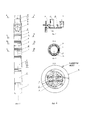
На фиг.1 изображена установка электропогружного шестеренного насоса, Figure 1 shows the installation of an electric submersible gear pump,
на фиг.2 – наземная часть установки,figure 2 - the ground part of the installation,
на фиг.3 – разрез А-А на фиг.1,figure 3 - section A-A in figure 1,
на фиг.4 – разрез Б-Б на фиг.1.figure 4 is a section b-b in figure 1.
Установка электропогружного шестеренного насоса содержит электрически связанный понижающий наземный трансформатор (ТМ) 19 двухступенчатого или каскадного снижения напряжения и силовой кабель 15, закрепленный к колонне насосно-компрессорных труб (НКТ) с помощью центраторов 18 и поясков 17, системы электропитания, станцию управления 20, наземный утепленный бак 21 с жидкостью с капельницей или насосом-дозатором и имеющей с силовым кабелем общую изоляционную и броневую защиту медной трубки 14 системы уплотнений и подземное оборудование, подвешенное на НКТ к устью скважины, в составе подземного понижающего трансформатора 1, к штекерному вводу которого подключен силовой кабель 15, электрически связанный с подземным электродвигателем 2, а также шестеренного насоса 4, собранного из одной или нескольких насосных пар (например 5-6, 5-7) с шевронными, прямозубыми, с двумя косозубыми шестернями с противоположным наклоном, эвольвентным зацеплением или зацеплением зубьев Новикова, опирающихся на упорную шайбу и заключенных в один или несколько корпусов-секций 8, имеющих профилированный всасывающий канал к каждой насосной паре, соединяющей затрубное пространство с пластовой жидкостью через фильтр, а выкидные каналы соединены с коллектором корпус-секции 8 и коллектором насоса 16, соединенного с НКТ подвески через клапанную коробку 9 с клапаном 10. При этом между электродвигателем и шестеренным насосом расположена камера уплотнений 3 с промежуточным валом 11 на опорах скольжения с подпятником 12, по концам которого расположены два уплотнения 13 контактного, контактно-щелевого или щелевого типа с неподвижными или плавающими кольцами, к которой подключены медная трубка, позволяющая поддерживать давление внутри выше, чем за корпусом и над давлением всасывания насоса на 0,03-0,05 МПа.The installation of an electric submersible gear pump contains an electrically connected step-down ground transformer (TM) 19 of a two-stage or cascade voltage reduction and a
Предлагаемое изобретение работает следующим образом.The proposed invention works as follows.
При подаче электроэнергии по системе электропитания на трансформатор 19 по силовому кабелю 15 через второй погружной трансформатор 1 под необходимым пониженным напряжением двигатель 2 начинает вращать шестерни рабочего шестеренного насоса 4, который засасывает через фильтр пластовую жидкость и под напором подает в коллектор секции 8, затем в коллектор насоса и в НКТ через клапанную коробку 10. Производительность и давление перекачиваемой жидкости зависит от количества насосных пар в секции и количества в секции насоса.When electricity is supplied through the power supply system to the
Таким образом, установки обеспечивают откачку пластовой жидкости со скважин практически с любым. При этом достигается максимальный КПД свыше 80-85% и даже выше. Установки компактны, имеет малую длину и массу и усилия трения минимум на 2/3 меньше, чем даже УЭГПН, с минимальной металлоемкостью и энергоемкостью, позволяют резко сократить материальные и эксплуатационные затраты, заменяют все существующие типы установок для добычи нефти и сокращают номенклатуру выпускаемых изделий до минимума. Установка проста по конструкции, в изготовлении, обслуживании, ремонте и эксплуатации, причем позволяет применение всего арсенала передовых технологий в добыче нефти и при изготовлении их на заводах-изготовителях, ремонте и эксплуатации.Thus, the units provide pumping of formation fluid from wells with almost any. At the same time, the maximum efficiency of over 80-85% and even higher is achieved. The plants are compact, have a small length and weight and friction forces are at least 2/3 less than even the UEGPN, with minimal metal consumption and energy consumption, they can drastically reduce material and operating costs, replace all existing types of oil production plants and reduce the range of manufactured products to minimum. The installation is simple in design, in manufacturing, maintenance, repair and operation, and allows the use of the entire arsenal of advanced technologies in oil production and during their manufacture at manufacturing plants, repair and operation.
Предлагаемое техническое решение можно применить на нефтепромыслах нашей страны, ближнего и дальнего зарубежья. При этом до разработки документации и начала серийного выпуска установок провести разработку и промысловые испытания экспериментальных установок в разных регионах страны.The proposed technical solution can be applied at the oil fields of our country, near and far abroad. At the same time, prior to the development of documentation and the start of serial production of installations, develop and field tests of experimental installations in different regions of the country.
Claims (3)
Priority Applications (1)
| Application Number | Priority Date | Filing Date | Title |
|---|---|---|---|
| RU2018130528A RU2746292C2 (en) | 2018-08-22 | 2018-08-22 | Electric submersible gear pump installation |
Applications Claiming Priority (1)
| Application Number | Priority Date | Filing Date | Title |
|---|---|---|---|
| RU2018130528A RU2746292C2 (en) | 2018-08-22 | 2018-08-22 | Electric submersible gear pump installation |
Publications (3)
| Publication Number | Publication Date |
|---|---|
| RU2018130528A RU2018130528A (en) | 2020-02-25 |
| RU2018130528A3 RU2018130528A3 (en) | 2020-02-25 |
| RU2746292C2 true RU2746292C2 (en) | 2021-04-12 |
Family
ID=69631243
Family Applications (1)
| Application Number | Title | Priority Date | Filing Date |
|---|---|---|---|
| RU2018130528A RU2746292C2 (en) | 2018-08-22 | 2018-08-22 | Electric submersible gear pump installation |
Country Status (1)
| Country | Link |
|---|---|
| RU (1) | RU2746292C2 (en) |
Citations (5)
| Publication number | Priority date | Publication date | Assignee | Title |
|---|---|---|---|---|
| US5573063A (en) * | 1995-07-05 | 1996-11-12 | Harrier Technologies, Inc. | Deep well pumping apparatus |
| CN101196184A (en) * | 2007-12-25 | 2008-06-11 | 马宝忠 | Electric gear pump |
| RU2536736C1 (en) * | 2013-11-07 | 2014-12-27 | Закрытое Акционерное Общество "Новомет-Пермь" | Gear wheel pump for fluid pumping |
| RU2605789C2 (en) * | 2015-04-10 | 2016-12-27 | Ахсян Аглямович Фасхутдинов | Installation of electric submersible hydraulic piston pump |
| RU2628840C1 (en) * | 2016-04-12 | 2017-08-22 | Вячеслав Абельевич Терпунов | Hydraulic borehole pump unit |
-
2018
- 2018-08-22 RU RU2018130528A patent/RU2746292C2/en not_active Application Discontinuation
Patent Citations (5)
| Publication number | Priority date | Publication date | Assignee | Title |
|---|---|---|---|---|
| US5573063A (en) * | 1995-07-05 | 1996-11-12 | Harrier Technologies, Inc. | Deep well pumping apparatus |
| CN101196184A (en) * | 2007-12-25 | 2008-06-11 | 马宝忠 | Electric gear pump |
| RU2536736C1 (en) * | 2013-11-07 | 2014-12-27 | Закрытое Акционерное Общество "Новомет-Пермь" | Gear wheel pump for fluid pumping |
| RU2605789C2 (en) * | 2015-04-10 | 2016-12-27 | Ахсян Аглямович Фасхутдинов | Installation of electric submersible hydraulic piston pump |
| RU2628840C1 (en) * | 2016-04-12 | 2017-08-22 | Вячеслав Абельевич Терпунов | Hydraulic borehole pump unit |
Also Published As
| Publication number | Publication date |
|---|---|
| RU2018130528A (en) | 2020-02-25 |
| RU2018130528A3 (en) | 2020-02-25 |
Similar Documents
| Publication | Publication Date | Title |
|---|---|---|
| RU2606196C2 (en) | Pump and pump section | |
| US2455022A (en) | Submersible double-acting fluid piston deep well pump | |
| CN1203654A (en) | Subsea pump system and related method | |
| RU2010118562A (en) | METHOD, DEVICE AND MAGNET FOR MAGNETIC PROCESSING OF FLUIDS | |
| CN106523334A (en) | Oil field downhole mechanical oil extraction device | |
| US20170191477A1 (en) | A downhole sucker rod pumping unit | |
| RU2605789C2 (en) | Installation of electric submersible hydraulic piston pump | |
| RU184849U1 (en) | Hydromechanical plunger pump drive | |
| RU2746292C2 (en) | Electric submersible gear pump installation | |
| RU2679775C9 (en) | Atrificial lifting system with base-mounted progressive cavity motor for extracting hydrocarbonds | |
| RU2515585C2 (en) | Improved borehole feeding system | |
| CN101255860B (en) | Oil-submersible electric membrane pump | |
| RU2037662C1 (en) | Deep-well lump plant | |
| EP0237145A2 (en) | Electrically powered pump unit | |
| RU2059112C1 (en) | Submersible pumping unit | |
| RU138124U1 (en) | INSTALLATION OF ELECTRIC SUBMERSIBLE HYDRAULIC PISTON PUMP | |
| CN101701515B (en) | Rodless Production System Driven by Downhole Rotating Motor | |
| CN104935104A (en) | Pressure compensation type submersible motor system | |
| RU2521534C2 (en) | Borehole electrically driven pump | |
| CN105201799B (en) | A submersible oil pump unit with downhole driving conversion device | |
| CN117905675A (en) | Submersible electric drive plunger pump | |
| CN213743963U (en) | Oil-well pump device for oil and gas exploitation | |
| CN107461320A (en) | Positive displacement pump and extracting device of oil | |
| RU103144U1 (en) | SUBMERSIBLE Borehole Diaphragm Pump | |
| CN202040053U (en) | Plunger-type diaphragm pump for submersible motor |
Legal Events
| Date | Code | Title | Description |
|---|---|---|---|
| FA92 | Acknowledgement of application withdrawn (lack of supplementary materials submitted) |
Effective date: 20200922 |
|
| HE9A | Changing address for correspondence with an applicant | ||
| FZ9A | Application not withdrawn (correction of the notice of withdrawal) |
Effective date: 20210129 |