RU2746110C1 - Body of device for positioning coronary stent or coronary balloon in coronary arteries - Google Patents
Body of device for positioning coronary stent or coronary balloon in coronary arteries Download PDFInfo
- Publication number
- RU2746110C1 RU2746110C1 RU2020121738A RU2020121738A RU2746110C1 RU 2746110 C1 RU2746110 C1 RU 2746110C1 RU 2020121738 A RU2020121738 A RU 2020121738A RU 2020121738 A RU2020121738 A RU 2020121738A RU 2746110 C1 RU2746110 C1 RU 2746110C1
- Authority
- RU
- Russia
- Prior art keywords
- cylindrical
- rear part
- circumference
- smooth
- protrusions
- Prior art date
Links
Images


Classifications
-
- A—HUMAN NECESSITIES
- A61—MEDICAL OR VETERINARY SCIENCE; HYGIENE
- A61F—FILTERS IMPLANTABLE INTO BLOOD VESSELS; PROSTHESES; DEVICES PROVIDING PATENCY TO, OR PREVENTING COLLAPSING OF, TUBULAR STRUCTURES OF THE BODY, e.g. STENTS; ORTHOPAEDIC, NURSING OR CONTRACEPTIVE DEVICES; FOMENTATION; TREATMENT OR PROTECTION OF EYES OR EARS; BANDAGES, DRESSINGS OR ABSORBENT PADS; FIRST-AID KITS
- A61F2/00—Filters implantable into blood vessels; Prostheses, i.e. artificial substitutes or replacements for parts of the body; Appliances for connecting them with the body; Devices providing patency to, or preventing collapsing of, tubular structures of the body, e.g. stents
- A61F2/95—Instruments specially adapted for placement or removal of stents or stent-grafts
- A61F2/9517—Instruments specially adapted for placement or removal of stents or stent-grafts handle assemblies therefor
-
- A—HUMAN NECESSITIES
- A61—MEDICAL OR VETERINARY SCIENCE; HYGIENE
- A61F—FILTERS IMPLANTABLE INTO BLOOD VESSELS; PROSTHESES; DEVICES PROVIDING PATENCY TO, OR PREVENTING COLLAPSING OF, TUBULAR STRUCTURES OF THE BODY, e.g. STENTS; ORTHOPAEDIC, NURSING OR CONTRACEPTIVE DEVICES; FOMENTATION; TREATMENT OR PROTECTION OF EYES OR EARS; BANDAGES, DRESSINGS OR ABSORBENT PADS; FIRST-AID KITS
- A61F2/00—Filters implantable into blood vessels; Prostheses, i.e. artificial substitutes or replacements for parts of the body; Appliances for connecting them with the body; Devices providing patency to, or preventing collapsing of, tubular structures of the body, e.g. stents
- A61F2/01—Filters implantable into blood vessels
- A61F2/011—Instruments for their placement or removal
-
- A—HUMAN NECESSITIES
- A61—MEDICAL OR VETERINARY SCIENCE; HYGIENE
- A61F—FILTERS IMPLANTABLE INTO BLOOD VESSELS; PROSTHESES; DEVICES PROVIDING PATENCY TO, OR PREVENTING COLLAPSING OF, TUBULAR STRUCTURES OF THE BODY, e.g. STENTS; ORTHOPAEDIC, NURSING OR CONTRACEPTIVE DEVICES; FOMENTATION; TREATMENT OR PROTECTION OF EYES OR EARS; BANDAGES, DRESSINGS OR ABSORBENT PADS; FIRST-AID KITS
- A61F2/00—Filters implantable into blood vessels; Prostheses, i.e. artificial substitutes or replacements for parts of the body; Appliances for connecting them with the body; Devices providing patency to, or preventing collapsing of, tubular structures of the body, e.g. stents
- A61F2/01—Filters implantable into blood vessels
-
- A—HUMAN NECESSITIES
- A61—MEDICAL OR VETERINARY SCIENCE; HYGIENE
- A61B—DIAGNOSIS; SURGERY; IDENTIFICATION
- A61B8/00—Diagnosis using ultrasonic, sonic or infrasonic waves
- A61B8/12—Diagnosis using ultrasonic, sonic or infrasonic waves in body cavities or body tracts, e.g. by using catheters
-
- A—HUMAN NECESSITIES
- A61—MEDICAL OR VETERINARY SCIENCE; HYGIENE
- A61F—FILTERS IMPLANTABLE INTO BLOOD VESSELS; PROSTHESES; DEVICES PROVIDING PATENCY TO, OR PREVENTING COLLAPSING OF, TUBULAR STRUCTURES OF THE BODY, e.g. STENTS; ORTHOPAEDIC, NURSING OR CONTRACEPTIVE DEVICES; FOMENTATION; TREATMENT OR PROTECTION OF EYES OR EARS; BANDAGES, DRESSINGS OR ABSORBENT PADS; FIRST-AID KITS
- A61F2250/00—Special features of prostheses classified in groups A61F2/00 - A61F2/26 or A61F2/82 or A61F9/00 or A61F11/00 or subgroups thereof
- A61F2250/0058—Additional features; Implant or prostheses properties not otherwise provided for
- A61F2250/0093—Ultrasound system, e.g. for inducing coagulation during eye surgery
-
- A—HUMAN NECESSITIES
- A61—MEDICAL OR VETERINARY SCIENCE; HYGIENE
- A61F—FILTERS IMPLANTABLE INTO BLOOD VESSELS; PROSTHESES; DEVICES PROVIDING PATENCY TO, OR PREVENTING COLLAPSING OF, TUBULAR STRUCTURES OF THE BODY, e.g. STENTS; ORTHOPAEDIC, NURSING OR CONTRACEPTIVE DEVICES; FOMENTATION; TREATMENT OR PROTECTION OF EYES OR EARS; BANDAGES, DRESSINGS OR ABSORBENT PADS; FIRST-AID KITS
- A61F2250/00—Special features of prostheses classified in groups A61F2/00 - A61F2/26 or A61F2/82 or A61F9/00 or A61F11/00 or subgroups thereof
- A61F2250/0058—Additional features; Implant or prostheses properties not otherwise provided for
- A61F2250/0096—Markers and sensors for detecting a position or changes of a position of an implant, e.g. RF sensors, ultrasound markers
Abstract
Description
Настоящее изобретение представляет собой корпус устройства, предназначенного для использования в медицине с целью максимально точного, быстрого и безопасного позиционирования коронарного стента на системе доставки при эндоваскулярной операции коронарного стентирования и протяжки датчика катетера внутрисосудистого ультразвукового исследования (далее - ВСУЗИ).The present invention is a body of a device intended for use in medicine for the most accurate, fast and safe positioning of a coronary stent on a delivery system during endovascular coronary stenting and pulling an intravascular ultrasound catheter transducer (hereinafter referred to as IVUS).
В случае использования устройства с протяжкой датчика катетера, датчик катетера размещается в устройстве вместо системы доставки коронарного стента аналогичным образом.In the case of a device with a catheter transducer pull, the catheter transducer is placed in the device instead of the coronary stent delivery system in a similar manner.
Для осуществления съемки внутри сосудов в устье коронарной артерии устанавливается катетер-гид, который с помощью коронарного проводника проводится через целевое сужение до дистальных отделов артерии. На цифровой катетер для ВСУЗИ надевается устройство, аналогично тому, как оно надевается на систему доставки коронарного стента. Использование механического датчика Revolution (Volcano (Philips)) или ему подобных с устройством в настоящий момент невозможно в связи с особенностью механизмов протяжки. Устройство устанавливается максимально близко к проксимальной части катетера-датчика - та часть, где катетер-датчик подключается проводом к станции или встроенному интерфейсу. По проводнику заводится датчик на 30-40 мм дистальнее целевого сегмента. В соответствующей зоне устройство фиксируется на цифровом катетере для ВСУЗИ, после чего с помощью вращения корпуса устройства датчик медленно продвигается по аналогичной методике позиционирования стента для высокоточной оценки данного участка.To carry out imaging inside the vessels, a guide catheter is installed at the mouth of the coronary artery, which is guided through the target narrowing with the help of a coronary conductor to the distal parts of the artery. The device is put on the digital IVUS catheter in the same way as it is put on the coronary stent delivery system. The use of a mechanical sensor Revolution (Volcano (Philips)) or the like with the device is currently impossible due to the peculiarity of the feed mechanisms. The device is installed as close as possible to the proximal part of the transducer catheter - the part where the transducer catheter is wired to the station or built-in interface. The transducer is inserted along the guide wire 30-40 mm distal to the target segment. In the appropriate area, the device is fixed on a digital IVUS catheter, after which, by rotating the device body, the sensor is slowly advanced in a similar manner to position the stent for highly accurate assessment of this area.
На рынке медицинского оборудования известны устройства для позиционирования стента в коронарных артериях того же заявителя (RU 2598798, RU 2652732, RU 2650038, RU 2661092, RU 2710216), корпус которых отличается от заявляемого изобретения, имеющего нижеследующие преимущества:Devices for positioning a stent in the coronary arteries of the same applicant are known on the medical equipment market (RU 2598798, RU 2652732, RU 2650038, RU 2661092, RU 2710216), the body of which differs from the claimed invention, having the following advantages:
- упрощение и сокращение времени сборки корпуса устройства за счет стяжки и кольца, а также отсутствие необходимости в использовании клея при соединении деталей;- simplification and reduction of the assembly time of the device body due to the tie and the ring, as well as the absence of the need to use glue when joining parts;
- повышение прочности изделия за счет использования стяжки и большего количества конусных выступов и соответствующих им конусных отверстий в передней части корпуса устройства;- increasing the strength of the product due to the use of a tie and a larger number of tapered protrusions and the corresponding tapered holes in the front of the device body;
- увеличение жесткости передней части корпуса устройства при работе фиксатора за счет утолщения стенки передней усеченной части корпуса в зоне размещения ушек фиксатора с выполнением по краям утолщенной стенки максимально возможного количества конусных выступов и соответствующих им конусных отверстий;- an increase in the rigidity of the front part of the device body during the operation of the latch due to the thickening of the wall of the front truncated part of the housing in the area of the lugs of the latch with the maximum possible number of conical protrusions and the corresponding conical holes along the edges of the thickened wall;
- возможность размещения коронарного стента на системе доставки внутри устройства без использования трубки за счет скругления внутри передней усеченной части корпуса и наличия фасок на задней торцевой части корпуса и бегунке в их центральном отверстии;- the possibility of placing a coronary stent on the delivery system inside the device without using a tube due to rounding inside the front truncated part of the body and the presence of chamfers on the rear end part of the body and the slider in their central opening;
- улучшение качества работы изделия при позиционировании коронарного стента за счет увеличения жесткости направляющих бегунка путем добавления стенки, соединяющей направляющие;- improving the quality of the product during the positioning of the coronary stent by increasing the rigidity of the slider guides by adding a wall connecting the guides;
- отсутствие необходимости склеивания и увеличение силы стыковки направляющих для бегунка передней части корпуса за счет использования на конце направляющих поперечных стенок, с конусным выступом и соответствующим ему конусным отверстием;- no need for gluing and an increase in the force of joining of the guides for the slider of the front part of the body due to the use of transverse walls at the end of the guide, with a tapered protrusion and a corresponding tapered hole;
- возможность использования корпуса устройства для протяжки датчика катетера;- the possibility of using the body of the device for pulling the catheter sensor;
- увеличение жесткости стыковки половинок задней части корпуса за счет добавления продольных пазов и продольных выступов по краю внутренней стороны задней части корпуса в зоне нахлеста;- increasing the rigidity of joining the halves of the rear part of the body by adding longitudinal grooves and longitudinal protrusions along the edge of the inner side of the rear part of the body in the overlap zone;
- предотвращение нарушения целостности корпуса устройства во время эксплуатации за счет фиксации стяжки выступами в торцевой части задней части корпуса устройства;- prevention of violation of the integrity of the device body during operation by fixing the tie with protrusions in the end part of the rear part of the device body;
- возможность поворота задней части корпуса устройства при позиционировании коронарного стента и при протяжке датчика катетера за кольцо за счет зацепления деталей;- the possibility of turning the rear part of the device body when positioning the coronary stent and when pulling the catheter sensor through the ring due to the engagement of the parts;
- предотвращение смещения стяжки вокруг задней части корпуса при позиционировании коронарного стента за счет продольных выступов на внешней стороне задней части корпуса в зоне внутренней резьбы и внутренних направляющих на стяжке.- prevention of the tie displacement around the back of the body when positioning the coronary stent due to the longitudinal protrusions on the outer side of the rear body in the area of the internal thread and internal guides on the tie.
- отсутствие необходимости точного позиционирования стяжки относительно задней части корпуса при сборке корпуса устройства, упрощение и сокращение времени сборки благодаря специальной форме продольных выступов на внешней стороне задней части корпуса устройства в зоне внутренней резьбы;- no need for precise positioning of the tie with respect to the rear of the body when assembling the body of the device, simplification and reduction of assembly time due to the special shape of the longitudinal projections on the outer side of the rear of the body of the device in the area of the internal thread
- снижение нагрузки на пальцы оператора при закрытии фиксатора за счет направленной под углом к точечному выступу стенки в отверстии для ушек фиксатора, предназначенному для удержания ушек фиксатора в крайнем положении.- reduction of the load on the operator's fingers when closing the retainer due to the wall directed at an angle to the point projection in the hole for the retainer lugs, designed to hold the lugs of the retainer in the extreme position.
Заявленное изобретение является промышленно применимым.The claimed invention is industrially applicable.
Предметом настоящего изобретения является корпус устройства для позиционирования коронарного стента на системе доставки в коронарных артериях и протяжки датчика катетера внутрисосудистого ультразвукового исследования.The subject of the present invention is a device housing for positioning a coronary stent on a coronary artery delivery system and pulling an intravascular ultrasound catheter transducer.
Корпус содержит фиксатор с утолщением с ушками, бегунок с отверстием для размещения в нем системы доставки с выступами, предназначенными для зацепления с внутренней двухзаходной резьбой задней цилиндрической части корпуса, и с выступами для перемещения по направляющим внутри корпуса с одной стороны, и колпачком с отверстием для размещения системы доставки с эластичной втулкой с отверстием для размещения системы доставки внутри с конусовидной и торцевой поверхностями, соответствующими таким же поверхностям внутри колпачка и на конце бегунка, помещенной в колпачке с резьбой для накручивания на бегунок с другой стороны.The housing contains a lock with a thickening with ears, a slider with an opening for placing a delivery system in it with protrusions designed to engage with the internal two-start thread of the rear cylindrical part of the housing, and with protrusions for moving along the guides inside the housing on one side, and a cap with an opening for placing a delivery system with an elastic sleeve with a hole for placing the delivery system inside with a tapered and end surfaces corresponding to the same surfaces inside the cap and at the end of the slider, placed in the cap with a thread for screwing onto the slider on the other side.
Механизм, размещенный в корпусе, является предметом отдельного патента на изобретение (патент RU 2661092) того же заявителя и приводится только в целях иллюстрации и понимания заявляемого изобретения.The mechanism housed in the housing is the subject of a separate invention patent (patent RU 2661092) by the same applicant and is provided for the purpose of illustration and understanding of the claimed invention only.
Корпус устройства состоит из двух элементов, один из которых представляет собой деталь, состоящую из усеченной передней части с одной стороны и цилиндрической части с другой стороны, гладкой цилиндрической части меньшего диаметра и направляющих для бегунка, и составляет переднюю часть корпуса, а другой элемент состоит из частей, одна из которых размещена поверх гладкой цилиндрической части первого элемента, и задней части с внутренней двухзаходной резьбой и фаской на торце, и составляет заднюю часть корпуса.The body of the device consists of two elements, one of which is a part consisting of a truncated front part on one side and a cylindrical part on the other side, a smooth cylindrical part of a smaller diameter and guides for the slider, and constitutes the front part of the body, and the other element consists of parts, one of which is placed on top of the smooth cylindrical part of the first element, and the rear part with an internal two-start thread and a chamfer at the end, and constitutes the rear part of the body.
Передняя часть корпуса представляет собой усеченную переднюю часть с одной стороны, а с другой стороны переходит последовательно в цилиндрическую часть, гладкую цилиндрическую часть меньшего диаметра, и направляющие для бегунка, соединенные продольными стенками и снабженные поперечным стенками на конце с соответствующими конусными отверстиями и конусными выступами для соединения половинок корпуса.The front part of the body is a truncated front part on one side, and on the other hand it goes sequentially into a cylindrical part, a smooth cylindrical part of a smaller diameter, and guides for the slider, connected by longitudinal walls and equipped with transverse walls at the end with corresponding tapered holes and tapered protrusions for connections of the halves of the case.
Передняя усеченная часть корпуса приспособлена для удержания пальцами левой руки хирурга, для чего снабжена выемками, позволяющими хирургу фиксировать устройство в нужном положении, при этом выемки служат также площадкой для фиксации коронарного проводника. Для более удобного размещения системы доставки коронарного стента и датчика катетера по бокам внутренней усеченной передней части корпуса, соответствующей месту расположения с наружной стороны выемок для пальцев левой руки оператора, в месте соприкосновения с устьем отверстия для размещения системы доставки выполнено скругление стенок.The front truncated part of the body is adapted to hold the surgeon's left hand with fingers, for which it is provided with recesses allowing the surgeon to fix the device in the desired position, while the recesses also serve as a platform for fixing the coronary conductor. For more convenient placement of the coronary stent delivery system and the catheter sensor on the sides of the inner truncated front part of the body corresponding to the location on the outer side of the recesses for the fingers of the operator's left hand, at the point of contact with the mouth of the opening for the delivery system, the walls are rounded.
Корпус в своей передней цилиндрической части по обеим сторонам снабжен прямоугольными отверстиями для ушек фиксатора, стенки передней части корпуса на участке между отверстиями для ушек фиксатора выполнены утолщенными. Причем в каждом из прямоугольных отверстий с одной стороны на расстоянии, равном ширине ушка фиксатора, размещены по два точечных выступа, предназначенных для удерживания ушек фиксатора в крайнем положении, а самого фиксатора в закрытом состоянии, выполненные каждый с одной плоской стенкой, направленной под углом к выступу со стороны открытого положения фиксатора, вдоль которой скользит ушко фиксатора при изменении своего положения, что снижает усилие руки оператора при повороте ушек фиксатора при закрытии механизма.The body in its front cylindrical part on both sides is provided with rectangular holes for the tabs, the walls of the front part of the body in the area between the holes for the tabs are made thickened. Moreover, in each of the rectangular holes on one side, at a distance equal to the width of the latch ear, there are two point projections designed to hold the lugs of the latch in the extreme position, and the latch itself in the closed state, each made with one flat wall directed at an angle to a protrusion on the side of the open position of the retainer, along which the tab of the retainer slides when its position changes, which reduces the effort of the operator's hand when turning the tabs when closing the mechanism.
На передней гладкой цилиндрической части корпуса размещено кольцо.A ring is placed on the front smooth cylindrical part of the body.
По всей внутренней окружности кольца выполнено углубление, в которое вставляются соответствующие выступы, выполненные по окружности половинок задней части корпуса со стороны фиксатора, с целью их стыковки.A recess is made along the entire inner circumference of the ring, into which the corresponding protrusions are inserted, made along the circumference of the halves of the rear part of the housing from the side of the retainer, in order to join them.
На внешней окружности кольца выполнены пазы в форме трапеции, в которых размещаются соответствующие выступы передней части задней части корпуса, выполненные в форме трапеции, которые фиксируют заднюю часть корпуса в кольце, предотвращая ее самопроизвольное вращение, при этом обеспечивая возможность вращения задней части корпуса относительно передней части корпуса за кольцо по усмотрению оператора.On the outer circumference of the ring, trapezoid-shaped grooves are made, in which the corresponding protrusions of the front part of the rear part of the body, made in the form of a trapezoid, are placed, which fix the rear part of the body in the ring, preventing its spontaneous rotation, while allowing the rear part of the body to rotate relative to the front part the case by the ring at the discretion of the operator.
По окружности торца гладкой цилиндрической части передней части корпуса со стороны направляющей бегунка выполнен цилиндрический паз с точечными элементами, предназначенный для соединения с соответствующим выступом с точечными элементами, выполненным по окружности внутренней гладкой цилиндрической поверхности задней части корпуса со стороны поверхности с двухзаходной резьбой.Around the end face of the smooth cylindrical part of the front part of the housing on the side of the runner guide, a cylindrical groove with dotted elements is made, intended for connection with the corresponding protrusion with dotted elements, made around the circumference of the inner smooth cylindrical surface of the rear part of the housing from the side of the surface with a double thread.
Задняя цилиндрическая часть корпуса с внутренней стороны по краям половинок в зоне гладкой цилиндрической поверхности выполнена с продольными выступами и соответствующими продольными пазами для соединения половинок задней части корпуса.The rear cylindrical part of the body from the inner side along the edges of the halves in the area of the smooth cylindrical surface is made with longitudinal protrusions and corresponding longitudinal grooves for connecting the halves of the rear part of the body.
На внутренней гладкой цилиндрической поверхности задней части корпуса со стороны фиксатора по окружности выполнены точечные элементы, предназначенные для снижения трения вращающихся относительно друг друга частей корпуса.On the inner smooth cylindrical surface of the rear part of the body, from the side of the retainer, point elements are made around the circumference, designed to reduce the friction of the parts of the body rotating relative to each other.
Между гладкой внутренней поверхностью и поверхностью с внутренней двухзаходной резьбой задней части корпуса по окружности выполнен цилиндрический выступ с точечными элементами для зацепления с цилиндрическим пазом гладкой цилиндрической части передней части корпуса со стороны направляющей бегунка с возможностью вращения задней цилиндрической части корпуса вокруг своей оси.Between the smooth inner surface and the surface with an internal two-start thread of the rear part of the body, a cylindrical protrusion with dotted elements is made around the circumference to engage with a cylindrical groove of the smooth cylindrical part of the front part of the body from the side of the runner guide with the possibility of rotation of the rear cylindrical part of the body around its axis.
На внешней поверхности задней части корпуса выполнены продольные выступы с плавно изогнутыми в противоположные стороны друг от друга концами для центрирования и предотвращения произвольного вращения надеваемой на заднюю часть корпуса стяжки. На задней торцевой части корпуса по окружности размещены выступы. с помощью которых осуществляется фиксация стяжки в отверстиях, выполненных по окружности ее торцевой части.On the outer surface of the rear part of the body, longitudinal projections are made with ends smoothly bent in opposite directions from each other for centering and preventing arbitrary rotation of the tie put on the rear part of the body. On the rear end part of the body there are protrusions along the circumference. with the help of which the fastening of the tie is carried out in the holes made around the circumference of its end part.
Поверх задней части корпуса в зоне с внутренней двухзаходной резьбой размещается стяжка.A tie is placed on top of the rear part of the body in the area with an internal two-start thread.
Стяжка представляет собой полый цилиндр с внутренними продольными направляющими по всей длине для плотного прилегания к внешней поверхности задней части корпуса, на внешней стороне которой для плотного закрепления стяжки предусмотрены соответствующие продольные выступы с плавно изогнутыми в противоположные друг от друга стороны концами.The tie is a hollow cylinder with internal longitudinal guides along the entire length for snug fit to the outer surface of the rear part of the body, on the outer side of which, for tight fastening of the tie, corresponding longitudinal protrusions are provided with ends smoothly bent in opposite directions from each other.
По окружности торца стяжки выполнены отверстия для фиксации стяжки на поверхности задней части корпуса с помощью соответствующих выступов по окружности торцевой поверхности задней части корпуса.Around the circumference of the end of the tie, holes are made for fixing the tie on the surface of the rear part of the housing with the help of corresponding protrusions along the circumference of the end surface of the rear part of the housing.
В передней части корпуса, бегунке, колпачке, эластичной втулке и торцевой поверхности задней части корпуса выполнены сквозные отверстия для введения системы доставки коронарного стента и датчика катетера внутрь устройства, размещенного в корпусе.In the front part of the body, the slider, the cap, the elastic sleeve and the end surface of the rear part of the body, through holes are made for introducing the delivery system of the coronary stent and the catheter sensor inside the device located in the body.
Для облегчения размещения коронарного стента на системе доставки, а также датчика катетера внутри устройства в центральном сквозном отверстии с торцевой стороны бегунка и задней части корпуса выполнены фаски.To facilitate placement of the coronary stent on the delivery system, as well as the catheter sensor inside the device, chamfers are made in the central through hole on the end side of the slider and the back of the housing.
Корпус выполнен из пластика методом литья под давлением и состоит из передней и задней частей, каждая из которых представляет собой две идентичные половинки.The body is made of plastic by injection molding and consists of a front and a back, each of which is two identical halves.
Каждая половинка передней и задней части корпуса отливаются целиком и соединяются между собой после сборки механизма с помощью конусных выступов и соответствующих им конусных отверстий, выполненных по внутренним краям передней и задней части корпуса и на поперечных стенках на конце направляющих бегунка. При этом выполняется максимально возможное количество конусных выступов и соответствующих им конусных отверстий на конусном выступе передней части корпуса и в зоне между отверстиями для ушек фиксатора.Each half of the front and rear parts of the body are cast entirely and are connected to each other after assembly of the mechanism using tapered protrusions and corresponding tapered holes made along the inner edges of the front and rear of the body and on the transverse walls at the end of the runner guides. In this case, the maximum possible number of tapered protrusions and the corresponding tapered holes are made on the tapered protrusion of the front part of the housing and in the area between the holes for the lugs of the retainer.
Половинки передней части корпуса соединяются с помощью конусных выступов и соответствующих им конусных отверстий, выполненных по внутреннему краю всего корпуса и конусных выступов и соответствующих им конусных отверстий, выполненных в поперечных стенках на конце направляющих, после соединения половинок передней части корпуса на гладкую цилиндрическую часть передней части корпуса со стороны направляющих для бегунка надевается кольцо, в углубление которого вставляются соответствующие выступы полуокружностей половинок задней части корпуса, а в пазы в форме трапеции, выполненные на внешней окружности кольца, вставляются соответствующие выступы на полуокружностях половинок передней части задней части корпуса, выполненные в форме трапеции, затем половинки соединяются таким образом, что гладкая цилиндрическая часть передней части корпуса размещается в половинках задней гладкой цилиндрической части корпуса, причем цилиндрический выступ с точечными элементами, выполненный между внутренней гладкой частью задней части корпуса и частью с внутренней двухзаходной резьбой размещается в цилиндрическом пазу гладкой цилиндрической части передней части корпуса со стороны направляющих бегунка, а половинки соединяются аналогично передней части корпуса с помощью конусных выступов и соответствующих им конусных отверстий, выполненных в задней части корпуса, и продольных пазов и продольных выступов по краям половинок задней гладкой части корпуса, образуя соединение внахлест с передней частью корпуса, после чего на заднюю часть корпуса с внутренней двухзаходной резьбой со стороны торца надевается цилиндрическая стяжка до фиксации на задней цилиндрической части корпуса таким образом, чтобы ее внутренние продольные направляющие располагались между наружными продольными выступами с плавно изогнутыми в противоположные стороны друг от друга концами задней части корпуса.The halves of the front part of the body are connected by means of conical protrusions and their corresponding conical holes made along the inner edge of the entire body and conical protrusions and their corresponding conical holes made in the transverse walls at the end of the guides, after connecting the halves of the front part of the case to the smooth cylindrical part of the front part on the side of the runner guides, a ring is put on, into the recess of which the corresponding protrusions of the semicircles of the halves of the rear part of the case are inserted, and the corresponding protrusions on the semicircles of the halves of the front part of the rear part of the case, made in the form of a trapezoid, are inserted into the trapezoidal grooves made on the outer circumference of the ring , then the halves are connected in such a way that the smooth cylindrical part of the front part of the body is located in the halves of the rear smooth cylindrical part of the body, and the cylindrical protrusion with dotted elements made between the inner smooth The th part of the rear part of the body and the part with an internal double-threaded thread is located in the cylindrical groove of the smooth cylindrical part of the front part of the body from the side of the slider guides, and the halves are connected similarly to the front part of the body using tapered protrusions and corresponding tapered holes made in the rear part of the body, and longitudinal grooves and longitudinal protrusions along the edges of the halves of the rear smooth part of the body, forming an overlapping connection with the front part of the body, after which a cylindrical tie is put on the rear part of the body with an internal double-threaded thread from the end side until it is fixed on the rear cylindrical part of the body so that its internal the longitudinal guides were located between the outer longitudinal protrusions with the ends of the rear part of the body smoothly bent in opposite directions from each other.
Вариант осуществления изобретения 2
В качестве варианта осуществления, внешняя поверхность задней части корпуса может быть выполнена гладкой без продольных выступов и их плавно изогнутых концов, но с сохранением внутренних продольных выступов на внутренней поверхности стяжки, в этом случае, стяжка фиксируется на задней части корпуса за счет усилия, которое появляется при трении поверхностей деталей и деформации стяжки. При этом размер диаметра стяжки должен быть таковым, чтобы обеспечивать соответствующий натяг стяжки на заднюю часть корпуса.As an embodiment, the outer surface of the rear part of the body can be made smooth without longitudinal protrusions and their smoothly curved ends, but retaining the inner longitudinal protrusions on the inner surface of the tie, in this case, the tie is fixed to the rear of the body due to the force that appears during friction of the surfaces of parts and deformation of the screed. In this case, the size of the screed diameter must be such as to ensure the appropriate tension of the screed on the rear of the housing.
Вариант осуществления изобретения 3Embodiment 3
В качестве варианта осуществления, задняя торцевая часть корпуса может быть выполнена без выступов по окружности для фиксации стяжки, а стяжка без соответствующих выступам отверстий, при этом фиксация одной детали относительно другой будет осуществляться за счет силы трения и натяга, образованного при деформации стяжки.As an embodiment, the rear end part of the body can be made without projections around the circumference for fixing the tie, and the tie without holes corresponding to the projections, while fixing one part relative to the other will be carried out due to the friction force and the tension formed during deformation of the tie.
Ниже приводится перечень прилагаемых чертежей.Below is a list of the accompanying drawings.
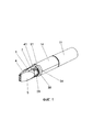
Фиг. 1 - общий вид корпуса устройства, гдеFIG. 1 is a general view of the device body, where
1 - передняя часть корпуса,1 - the front of the body,
4 - усеченная часть передней части корпуса,4 - a truncated part of the front of the body,
5 - выемки для пальцев,5 - recesses for the fingers,
7 - цилиндрическая часть передней части корпуса,7 - cylindrical part of the front of the body,
14 - задняя часть корпуса,14 - the back of the case,
28 - фиксатор,28 - retainer,
30 - ушки фиксатора,30 - retainer ears,
31 - стяжка,31 - screed,
34 - кольцо для фиксации задней части корпуса,34 - ring for fixing the back of the case,
41 - утолщенная стенка передней части корпуса в зоне между отверстиями для ушек фиксатора,41 - thickened wall of the front part of the body in the area between the holes for the lugs of the retainer,
51 - выступ в форме трапеции задней части корпуса для зацепления с кольцом.51 - trapezoidal protrusion of the rear of the housing for engaging with the ring.
Фиг. 2 - вид корпуса устройства сбоку, гдеFIG. 2 - side view of the device body, where
4 - усеченная часть передней части корпуса,4 - a truncated part of the front of the body,
5 - выемки для пальцев,5 - recesses for the fingers,
10 - точечный выступ для удержания ушек фиксатора,10 - point projection for holding the lugs of the retainer,
14 - задняя часть корпуса,14 - the back of the case,
28 - фиксатор,28 - retainer,
30 - ушки фиксатора,30 - retainer ears,
31 - стяжка,31 - screed,
32 - отверстия по окружности торца стяжки для крепления на задней части корпуса,32 - holes around the circumference of the end of the tie for attachment to the rear of the case,
34 - кольцо для фиксации задней части корпуса,34 - ring for fixing the back of the case,
41 - утолщенная стенка передней части корпуса в зоне между отверстиями для ушек фиксатора.41 - thickened wall of the front part of the housing in the area between the holes for the tabs.
Фиг. 3 - вид корпуса сверху, гдеFIG. 3 - top view of the case, where
1 - передняя часть корпуса,1 - the front of the body,
5 - выемки для пальцев,5 - recesses for the fingers,
15 - выступы на задней торцевой части корпуса по окружности для фиксации стяжки,15 - protrusions on the rear end part of the body around the circumference for fixing the tie,
28 - фиксатор,28 - retainer,
30 - ушки фиксатора,30 - retainer ears,
31 - стяжка,31 - screed,
34 - кольцо для фиксации задней части корпуса,34 - ring for fixing the back of the case,
41 - утолщенная стенка передней части корпуса в зоне между отверстиями для ушек фиксатора,41 - thickened wall of the front part of the body in the area between the holes for the lugs of the retainer,
51 - выступ в форме трапеции задней части корпуса для фиксации в кольце.51 - trapezoidal protrusion of the rear part of the housing for fixing in the ring.
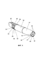
Фиг. 4 - общий вид корпуса устройства, гдеFIG. 4 is a general view of the device body, where
10 - точечный выступ для удержания ушек фиксатора,10 - point projection for holding the lugs of the retainer,
14 - задняя часть корпуса,14 - the back of the case,
15 - выступы на задней торцевой части корпуса по окружности для фиксации стяжки,15 - protrusions on the rear end part of the body around the circumference for fixing the tie,
21 - сквозное отверстие для системы доставки коронарного стента и датчика катетера,21 - through hole for the delivery system of the coronary stent and the catheter sensor,
28 - фиксатор,28 - retainer,
30 - ушки фиксатора,30 - retainer ears,
31 - стяжка,31 - screed,
32 - отверстия по окружности торца стяжки для крепления на задней части корпуса,32 - holes around the circumference of the end of the tie for attachment to the rear of the case,
34 - кольцо для фиксации задней корпуса,34 - ring for fixing the back case,
36 - паз кольца в форме трапеции для фиксации задней части корпуса,36 - trapezoidal ring groove for fixing the back of the case,
41 - утолщенная стенка передней части корпуса в зоне между отверстиями для ушек фиксатора,41 - thickened wall of the front part of the body in the area between the holes for the lugs of the retainer,
42 - фаска с отверстием для системы доставки в задней части корпуса,42 - chamfer with a hole for the delivery system in the rear of the body,
51 - выступ в форме трапеции половинок задней части корпуса для фиксации кольцом,51 - a trapezoidal protrusion of the halves of the rear part of the body for fixing with a ring,
54 - плоская стенка точечных выступов в прямоугольных отверстиях для ушек фиксатора.54 — Flat wall of pinpoint projections in rectangular holes for retainer tabs.
Фиг. 5 - вид корпуса устройства без стяжки, гдеFIG. 5 - view of the device body without a coupler, where
1 - передняя часть корпуса,1 - the front of the body,
14 - задняя часть корпуса,14 - the back of the case,
15 - выступы на задней торцевой части корпуса по окружности для фиксации стяжки,15 - protrusions on the rear end part of the body around the circumference for fixing the tie,
28 - фиксатор,28 - retainer,
41 - утолщенная стенка передней части корпуса в зоне между отверстиями для ушек фиксатора,41 - thickened wall of the front part of the body in the area between the holes for the lugs of the retainer,
50 - выступ по окружности половинок задней части корпуса для соединения кольцом,50 - protrusion around the circumference of the halves of the rear part of the body for ring connection,
51 - выступ в форме трапеции половинок задней части корпуса для фиксации кольцом,51 - a trapezoidal protrusion of the halves of the rear part of the body for fixing with a ring,
52 - продольные выступы на внешней стороне задней части корпуса для центрирования стяжки,52 - longitudinal projections on the outer side of the rear part of the body for centering the tie,
53 - плавно изогнутые концы продольного выступа на внешней стороне задней части корпуса.53 - smoothly curved ends of a longitudinal protrusion on the outside of the rear of the body.
Фиг. 6 - вид корпуса в разрезе с фиксатором, гдеFIG. 6 is a sectional view of the case with a retainer, where
1 - передняя часть корпуса,1 - the front of the body,
2 - конусный выступ передней части корпуса,2 - conical protrusion of the front of the body,
3 - конусное отверстие передней части корпуса,3 - tapered hole in the front of the body,
6 - отверстие для системы доставки и датчика катетера в передней части корпуса,6 - hole for the delivery system and the catheter sensor in the front of the body,
14 - задняя часть корпуса,14 - the back of the case,
22 - конусный выступ задней части корпуса,22 - tapered protrusion of the rear part of the body,
23 - конусное отверстие задней части корпуса,23 - tapered hole in the rear of the body,
24 - бегунок,24 - slider,
28 - фиксатор,28 - retainer,
29 - утолщение фиксатора,29 - thickening of the retainer,
40 - колпачок.40 - cap.
46 - конусный выступ поперечной стенки на конце направляющей,46 - tapered protrusion of the transverse wall at the end of the guide,
47 - конусное отверстие поперечной стенки на конце направляющей,47 - tapered hole of the transverse wall at the end of the guide,
48 - продольные пазы внутренней гладкой задней части корпуса,48 - longitudinal grooves of the inner smooth rear part of the body,
49 - продольные выступы внутренней гладкой задней части корпуса,49 - longitudinal projections of the inner smooth rear part of the body,
50 - выступ по окружности половинок задней части корпуса для соединения кольцом,50 - protrusion around the circumference of the halves of the rear part of the body for ring connection,
55 - конусный выступ утолщенной стенки передней части корпуса,55 - conical protrusion of the thickened wall of the front part of the body,
56 - конусное отверстие утолщенной стенки передней части корпуса.56 - conical hole of the thickened wall of the front part of the body.
Фиг. 7 - вид корпуса в разрезе со смещенной резьбой, гдеFIG. 7 is a cross-sectional view of the body with an offset thread, where
20 - внутренняя двухзаходная резьба задней части корпуса для зацепления с бегунком,20 - internal double-start thread of the rear part of the body for engaging with the slider,
21 - сквозное отверстие для системы доставки коронарного стента и датчика катетера в торцевой части корпуса,21 - through hole for the delivery system of the coronary stent and the catheter sensor in the end part of the body,
24 - бегунок,24 - slider,
25 - сквозное отверстие в бегунке для системы доставки коронарного стента и датчика катетера,25 - through hole in the slider for the coronary stent delivery system and the catheter sensor,
26 - выступ бегунка для зацепления с резьбой внутренней поверхности задней части корпуса,26 - the protrusion of the slider for engaging with the thread of the inner surface of the rear part of the housing,
28 - фиксатор,28 - retainer,
29 - утолщение фиксатора,29 - thickening of the retainer,
31 - стяжка,31 - screed,
34 - кольцо для фиксации задней части корпуса,34 - ring for fixing the back of the case,
35 - углубление по внутренней окружности кольца для соединения половинок задней части корпуса,35 - recess along the inner circumference of the ring for connecting the halves of the rear part of the body,
40 - колпачек,40 - cap,
43 - внутреннее скругление стенок конусного отверстия передней части корпуса,43 - inner rounding of the walls of the tapered hole of the front part of the body,
45 - поперечная стенка на конце направляющей передней части корпуса.45 - transverse wall at the end of the front part of the housing.
Фиг. 8 - вид корпуса в разрезе со стяжкой, гдеFIG. 8 is a sectional view of the body with a coupler, where
1 - передняя часть корпуса,1 - the front of the body,
13 - направляющие для бегунка,13 - guides for the slider,
14 - задняя часть корпуса,14 - the back of the case,
15 - выступы для фиксации стяжки,15 - projections for fixing the screed,
16- - фаска задней торцевой части корпуса,16- - chamfer of the rear end part of the body,
20 - внутренняя двухзаходная резьба задней части корпуса для зацепления с бегунком,20 - internal double-start thread of the rear part of the body for engaging with the slider,
24 - бегунок,24 - slider,
25 - отверстие в бегунке для системы доставки и датчика катетера,25 - hole in the runner for the delivery system and the catheter sensor,
27 - выступ для направляющих передней части корпуса,27 - protrusion for the guides of the front of the body,
28 - фиксатор,28 - retainer,
31 - цилиндрическая стяжка,31 - cylindrical coupler,
34 - кольцо для фиксации задней части корпуса,34 - ring for fixing the back of the case,
35 - углубление по внутренней окружности кольца для соединения половинок задней части корпуса,35 - recess along the inner circumference of the ring for connecting the halves of the rear part of the body,
37 - отверстие фаски для системы доставки и датчика катетера в бегунке,37 - chamfer hole for the delivery system and the catheter sensor in the runner,
38 - торцевая поверхность задней части корпуса,38 - end surface of the rear part of the body,
40 - колпачок,40 - cap,
41 - утолщенная стенка передней части корпуса в зоне между отверстиями для ушек фиксатора,41 - thickened wall of the front part of the body in the area between the holes for the lugs of the retainer,
42 - отверстие фаски для системы доставки и датчика катетера в задней части корпуса,42 - chamfer hole for the delivery system and the catheter sensor in the back of the body,
43 - внутреннее скругление стенок конусного отверстия передней части корпуса.43 - inner rounding of the walls of the tapered hole in the front part of the housing.
Фиг. 9 - общий вид передней части корпуса после соединения с задней частью корпуса, гдеFIG. 9 is a general view of the front of the housing after being connected to the rear of the housing, where
1 - передняя часть корпуса,1 - the front of the body,
10 - точечный выступ для удержания ушек фиксатора,10 - point projection for holding the lugs of the retainer,
14 - задняя часть корпуса,14 - the back of the case,
28 - фиксатор,28 - retainer,
34 - кольцо для фиксации задней части корпуса,34 - ring for fixing the back of the case,
41 - утолщенная стенка передней части корпуса в зоне между отверстиями для ушек фиксатора,41 - thickened wall of the front part of the body in the area between the holes for the lugs of the retainer,
51 - выступ в форме трапеции половинок задней части корпуса для фиксации кольцом,51 - a trapezoidal protrusion of the halves of the rear part of the body for fixing with a ring,
54 - плоская стенка точечных выступов в прямоугольных отверстиях для ушек фиксатора.54 — Flat wall of pinpoint projections in rectangular holes for retainer tabs.
Фиг. 10 - общий вид устройства в разборе, гдеFIG. 10 is a general view of the disassembled device, where
1 - передняя часть корпуса,1 - the front of the body,
7 - цилиндрическая часть передней части корпуса,7 - cylindrical part of the front of the body,
8 - отверстия в передней цилиндрической части корпуса для ушек фиксатора,8 - holes in the front cylindrical part of the body for the lugs of the retainer,
9 - гладкая цилиндрическая часть передней части корпуса,9 - smooth cylindrical part of the front part of the body,
11 - цилиндрический паз гладкой цилиндрической части передней части корпуса,11 - cylindrical groove of the smooth cylindrical part of the front part of the body,
12 - точечные элементы цилиндрического паза передней части корпуса,12 - point elements of the cylindrical groove of the front part of the body,
13 - направляющие для бегунка,13 - guides for the slider,
14 - задняя часть корпуса,14 - the back of the case,
17 - точечные элементы внутренней гладкой задней части корпуса,17 - point elements of the inner smooth rear part of the body,
18 - цилиндрический выступ,18 - cylindrical ledge,
19 - точечные элементы цилиндрического выступа,19 - point elements of a cylindrical protrusion,
20 - внутренняя двухзаходная резьба задней части корпуса,20 - internal double-start thread of the rear part of the body,
24 - бегунок,24 - slider,
26 - направляющие бегунка для зацепления с резьбой внутренней поверхности задней части корпуса,26 - runner guides for engaging with the thread of the inner surface of the rear part of the body,
27 - выступ для направляющих передней части корпуса,27 - protrusion for the guides of the front of the body,
28 - фиксатор,28 - retainer,
29 - утолщение фиксатора,29 - thickening of the retainer,
30 - ушки фиксатора,30 - retainer ears,
31 - стяжка,31 - screed,
33 - внутренние продольные выступы на стяжке,33 - internal longitudinal protrusions on the screed,
34 - кольцо для фиксации задней части корпуса,34 - ring for fixing the back of the case,
35 - углубление по внутренней окружности кольца для соединения половинок задней части корпуса,35 - recess along the inner circumference of the ring for connecting the halves of the rear part of the body,
36 - паз кольца в форме трапеции для фиксации задней части корпуса,36 - trapezoidal ring groove for fixing the back of the case,
38 - торцевая поверхность задней части корпуса,38 - end surface of the rear part of the body,
44 - продольные стенки для соединения направляющих передней части корпуса,44 - longitudinal walls for connecting the guides of the front of the body,
45 - поперечные стенки на конце направляющей передней части корпуса,45 - transverse walls at the end of the guide of the front of the body,
48 - продольные пазы внутренней гладкой задней части корпуса,48 - longitudinal grooves of the inner smooth rear part of the body,
49 - продольные выступы внутренней гладкой задней части корпуса,49 - longitudinal projections of the inner smooth rear part of the body,
50 - выступ по окружности половинок задней части корпуса для соединения кольцом,50 - protrusion around the circumference of the halves of the rear part of the body for ring connection,
51 - выступ в форме трапеции половинок задней части корпуса для фиксации кольцом,51 - a trapezoidal protrusion of the halves of the rear part of the body for fixing with a ring,
52 - продольные выступы на внешней стороне задней части корпуса для центрирования стяжки,52 - longitudinal projections on the outer side of the rear part of the body for centering the tie,
53 - плавно изогнутые концы продольного выступа на внешней стороне задней части корпуса.53 - smoothly curved ends of a longitudinal protrusion on the outside of the rear of the body.
Ниже приводится осуществление изобретения со ссылкой на приложенные чертежи.Below is an implementation of the invention with reference to the accompanying drawings.
Корпус устройства состоит из двух элементов, один из которых представляет собой деталь, состоящую из усеченной передней части 4 (Фиг. 1, Фиг. 2) с одной стороны и цилиндрической части 7 (Фиг. 1, Фиг. 10) с другой стороны, гладкой цилиндрической части меньшего диаметра 9 (Фиг. 10) и направляющих 13 (Фиг. 8, Фиг. 10) для бегунка 24 (Фиг. 6, Фиг. 7, Фиг. 8, Фиг. 10) с фаской 37 (Фиг. 8) со сквозным отверстием 21 (Фиг. 4, Фиг. 7) для системы доставки или датчика катетера, и составляет переднюю часть корпуса 1 (Фиг. 1, Фиг. 3, Фиг. 5, Фиг. 6, Фиг. 8, Фиг. 9, Фиг. 10), а другой элемент состоит из частей, одна из которых размещена поверх гладкой цилиндрической части первого элемента 9 (Фиг. 10), и задней части с внутренней двухзаходной резьбой 20 (Фиг. 7, Фиг. 8, Фиг. 10) и фаской 16 (Фиг. 8) на торцевой части 38 (Фиг. 8) со сквозным отверстием 21 (Фиг. 4, Фиг. 7) для системы доставки или датчика катетера, и составляет заднюю часть корпуса 14 (Фиг. 1, Фиг. 2, Фиг. 3, Фиг. 4, Фиг. 5, Фиг. 6, Фиг. 8, Фиг. 9, Фиг. 10).The body of the device consists of two elements, one of which is a part consisting of a truncated front part 4 (Fig. 1, Fig. 2) on one side and a cylindrical part 7 (Fig. 1, Fig. 10) on the other, smooth a cylindrical part of a smaller diameter 9 (Fig. 10) and guides 13 (Fig. 8, Fig. 10) for the slider 24 (Fig. 6, Fig. 7, Fig. 8, Fig. 10) with a chamfer 37 (Fig. 8) with a through hole 21 (Fig. 4, Fig. 7) for the delivery system or the catheter sensor, and constitutes the front part of the body 1 (Fig. 1, Fig. 3, Fig. 5, Fig. 6, Fig. 8, Fig. 9 , Fig. 10), and the other element consists of parts, one of which is placed over the smooth cylindrical part of the first element 9 (Fig. 10), and a rear part with an internal two-start thread 20 (Fig. 7, Fig. 8, Fig. 10 ) and a chamfer 16 (Fig. 8) on the end part 38 (Fig. 8) with a through hole 21 (Fig. 4, Fig. 7) for a delivery system or a catheter sensor, and constitutes the rear part of the body 14 (Fig. 1, Fig. Fig. 2, Fig. 3, Fig. 4, Fig. 5, Fig. 6, F ig. 8, Fig. 9, Fig. 10).
Передняя часть корпуса представляет собой усеченную переднюю часть 4 (Фиг. 1, Фиг. 2) с одной стороны, а с другой стороны переходит последовательно в цилиндрическую часть 7 (Фиг. 1, Фиг. 10), гладкую цилиндрическую часть меньшего диаметра 9 (Фиг. 10), и направляющие 13 (Фиг. 8, Фиг. 10) для бегунка 24 (Фиг. 6, Фиг. 7, Фиг 8, Фиг. 10), соединенные продольными стенками 44 (Фиг. 8, Фиг. 10) и снабженные на конце со стороны торцевой части корпуса поперечными стенками 45 (Фиг. 7, Фиг. 10) с соответствующими конусными отверстиями 46 (Фиг. 6) и конусными выступами 47 (Фиг. 6) для соединения половинок корпуса.The front part of the body is a truncated front part 4 (Fig. 1, Fig. 2) on the one hand, and on the other side it passes successively into the cylindrical part 7 (Fig. 1, Fig. 10), a smooth cylindrical part of a smaller diameter 9 (Fig. . 10), and guides 13 (Fig. 8, Fig. 10) for the slider 24 (Fig. 6, Fig. 7, Fig. 8, Fig. 10), connected by longitudinal walls 44 (Fig. 8, Fig. 10) and provided at the end from the side of the end part of the housing with transverse walls 45 (Fig. 7, Fig. 10) with corresponding tapered holes 46 (Fig. 6) and tapered protrusions 47 (Fig. 6) for connecting the halves of the housing.
Передняя усеченная часть корпуса 4 (Фиг. 1, Фиг. 2) приспособлена для удержания пальцами левой руки хирурга, для чего снабжена выемками 5 (Фиг. 1, Фиг. 2, Фиг. 3), позволяющими хирургу фиксировать устройство в нужном положении, при этом выемки 5 (Фиг. 1, Фиг. 2, Фиг. 3) служат также площадкой для фиксации коронарного проводника. Для более удобного размещения системы доставки коронарного стента и датчика катетера по бокам внутренней усеченной передней части корпуса 4 (Фиг. 1. Фиг. 21, соответствующей месту расположения с наружной стороны выемок 5 (Фиг. 1. Фиг. 2. Фиг. 31 для пальцев левой руки оператора, в месте соприкосновения с устьем отверстия 6 (Фиг. 6) для размещения системы доставки и датчика катетера выполнено скругление стенок 43 (Фиг. 7, Фиг. 8).The front truncated part of the body 4 (Fig. 1, Fig. 2) is adapted to be held by the fingers of the surgeon's left hand, for which it is equipped with recesses 5 (Fig. 1, Fig. 2, Fig. 3), allowing the surgeon to fix the device in the desired position, when In this case, the recesses 5 (Fig. 1, Fig. 2, Fig. 3) also serve as a platform for fixing the coronary conductor. For a more convenient placement of the delivery system of the coronary stent and the catheter sensor on the sides of the inner truncated front part of the housing 4 (Fig. 1. Fig. 21 corresponding to the location on the outside of the recesses 5 (Fig. 1. Fig. 2. Fig. 31 for fingers of the operator's left hand, at the point of contact with the mouth of the opening 6 (Fig. 6) to accommodate the delivery system and the catheter sensor, the
Корпус 1 (Фиг. 1, Фиг. 3, Фиг. 5, Фиг. 6, Фиг. 8, Фиг. 9, Фиг. 10) в своей передней цилиндрической части 7 (Фиг. 1, Фиг. 10) по обеим сторонам снабжен прямоугольными отверстиями 8 (Фиг. 10) для ушек 30 (Фиг. 1, Фиг. 2, Фиг. 3, Фиг. 4, Фиг. 10) фиксатора 28 (Фиг. 1, Фиг. 2, Фиг. 3, Фиг. 4, Фиг. 5, Фиг. 6, Фиг. 7, Фиг. 8, Фиг. 9, Фиг. 10), в зоне между которыми рядом с усеченной передней частью 4 (Фиг. 1, Фиг. 2) стенки передней части корпуса 1 (Фиг. 1, Фиг. 3, Фиг. 5, Фиг. 6, Фиг. 8, Фиг. 9, Фиг. 10) выполнены с утолщением (41) (Фиг. 1, Фиг. 2, Фиг. 3, Фиг. 4, Фиг. 5, Фиг. 8, Фиг. 9). Причем в каждом из прямоугольных отверстий 8 (Фиг. 10) с одной стороны на расстоянии, равном ширине ушка 30 (Фиг. 1, Фиг. 2, Фиг. 3, Фиг. 4, Фиг. 10) фиксатора 28 (Фиг. 1, Фиг. 2, Фиг. 3, Фиг. 4, Фиг. 5, Фиг. 6, Фиг. 7, Фиг. 8, Фиг. 9, Фиг. 10), размещены по два точечных выступа 10 (Фиг. 2, Фиг. 4, Фиг. 9), предназначенных для удерживания ушек 30 (Фиг. 1, Фиг. 2, Фиг. 3, Фиг. 4, Фиг. 10) фиксатора 28 (Фиг. 1, Фиг. 2, Фиг. 3, Фиг. 4, Фиг. 5, Фиг. 6, Фиг. 7, Фиг. 8, Фиг. 9, Фиг. 10) в крайнем положении, а самого фиксатора 28 (Фиг. 1, Фиг. 2, Фиг. 3, Фиг. 4, Фиг. 5, Фиг. 6, Фиг. 7, Фиг. 8, Фиг. 9, Фиг. 10) в закрытом состоянии, и выполненных каждый с одной, направленной под углом к выступу 10 (Фиг. 2, Фиг. 4, Фиг. 9) со стороны открытого положения фиксатора плоской стенкой 54 (Фиг. 9), вдоль которой скользит ушко 30 (Фиг. 1, Фиг. 2, Фиг. 3, Фиг. 4, Фиг. 10) фиксатора 28 (Фиг. 1, Фиг. 2, Фиг. 3, Фиг. 4, Фиг. 5, Фиг. 6, Фиг. 7, Фиг. 8, Фиг. 9, Фиг. 10) при изменении своего положения, что снижает усилие руки оператора при повороте ушек 30 (Фиг. 1, Фиг. 2, Фиг. 3, Фиг. 4, Фиг. 10) фиксатора 28 (Фиг. 1, Фиг. 2, Фиг. 3, Фиг. 4, Фиг. 5, Фиг. 6, Фиг. 7, Фиг. 8, Фиг. 9, Фиг. 10) при закрытии механизма.The body 1 (Fig. 1, Fig. 3, Fig. 5, Fig. 6, Fig. 8, Fig. 9, Fig. 10) in its front cylindrical part 7 (Fig. 1, Fig. 10) is provided on both sides with rectangular holes 8 (Fig. 10) for tabs 30 (Fig. 1, Fig. 2, Fig. 3, Fig. 4, Fig. 10) of the retainer 28 (Fig. 1, Fig. 2, Fig. 3, Fig. 4 , Fig. 5, Fig. 6, Fig. 7, Fig. 8, Fig. 9, Fig. 10), in the area between which next to the truncated front part 4 (Fig. 1, Fig. 2) the walls of the front part of the housing 1 (Fig. 1, Fig. 3, Fig. 5, Fig. 6, Fig. 8, Fig. 9, Fig. 10) are made with a thickening (41) (Fig. 1, Fig. 2, Fig. 3, Fig. 10). 4, Fig. 5, Fig. 8, Fig. 9). Moreover, in each of the rectangular holes 8 (Fig. 10) on one side at a distance equal to the width of the tab 30 (Fig. 1, Fig. 2, Fig. 3, Fig. 4, Fig. 10) of the latch 28 (Fig. 1, Fig. 2, Fig. 3, Fig. 4, Fig. 5, Fig. 6, Fig. 7, Fig. 8, Fig. 9, Fig. 10), there are two point protrusions 10 (Fig. 2, Fig. 10). 4, Fig. 9), designed to hold the tabs 30 (Fig. 1, Fig. 2, Fig. 3, Fig. 4, Fig. 10) of the latch 28 (Fig. 1, Fig. 2, Fig. 3, Fig. Fig. 4, Fig. 5, Fig. 6, Fig. 7, Fig. 8, Fig. 9, Fig. 10) in the extreme position, and the
На передней гладкой цилиндрической части корпуса 9 (Фиг. 10) размещено кольцо 34 (Фиг. 1, Фиг. 2, Фиг. 3, Фиг. 4, Фиг. 7, Фиг. 8, Фиг. 9, Фиг. 10).On the front smooth cylindrical part of the body 9 (Fig. 10) there is a ring 34 (Fig. 1, Fig. 2, Fig. 3, Fig. 4, Fig. 7, Fig. 8, Fig. 9, Fig. 10).
По всей внутренней окружности кольца 34 (Фиг. 1, Фиг. 2, Фиг. 3, Фиг. 4, Фиг. 7, Фиг. 8, Фиг. 9, Фиг. 10) выполнено углубление 35 (Фиг. 7, Фиг. 8, Фиг. 10), в которое вставляются соответствующие выступы 50 (Фиг. 5, Фиг. 6, Фиг. 10), выполненные по окружности половинок задней части корпуса 14 (Фиг. 1, Фиг. 2, Фиг. 3, Фиг. 4, Фиг. 5, Фиг. 6, Фиг. 8, Фиг. 9, Фиг. 10) со стороны фиксатора 28 (Фиг. 1, Фиг. 2, Фиг. 3, Фиг. 4, Фиг. 5, Фиг. 6, Фиг. 7, Фиг. 8, Фиг. 9, Фиг. 10) с целью их стыковки.A
На внешней окружности кольца 34 (Фиг. 1, Фиг. 2, Фиг. 3, Фиг. 4, Фиг. 7, Фиг. 8, Фиг. 9, Фиг. 10) выполнены пазы 36 (Фиг. 4, Фиг. 10) в форме трапеции, в которых размещаются соответствующие выступы 51 (Фиг. 1, Фиг. 3, Фиг. 4, Фиг. 5, Фиг. 9, Фиг. 10) передней части задней части корпуса 14 (Фиг. 1, Фиг. 2, Фиг. 3, Фиг. 4, Фиг. 5, Фиг. 6, Фиг. 8, Фиг. 9, Фиг. 10), выполненные в форме трапеции, которые фиксирует заднюю часть корпуса 14 (Фиг. 1, Фиг. 2, Фиг. 3, Фиг. 4, Фиг. 5, Фиг. 6, Фиг. 8, Фиг. 9, Фиг. 10) в кольце 34 (Фиг. 1, Фиг. 2, Фиг. 3, Фиг. 4, Фиг. 7, Фиг. 8, Фиг. 9, Фиг. 10), предотвращая ее самопроизвольное вращение.On the outer circumference of the ring 34 (Fig. 1, Fig. 2, Fig. 3, Fig. 4, Fig. 7, Fig. 8, Fig. 9, Fig. 10)
По окружности торца гладкой цилиндрической части передней части корпуса 9 (Фиг. 10) со стороны направляющей 13 (Фиг. 8, Фиг. 10) бегунка 24 (Фиг. 6, Фиг. 7, Фиг. 8, Фиг. 10) выполнен цилиндрический паз 11 (Фиг. 10) с точечными элементами 12 (Фиг. 10), предназначенный для соединения с соответствующим выступом 18 (Фиг. 10) с точечными элементами 19 (Фиг. 10), выполненным по окружности внутренней гладкой цилиндрической поверхности задней части корпуса 14 (Фиг. 1, Фиг. 2, Фиг. 3, Фиг. 4, Фиг. 5, Фиг. 6, Фиг. 8, Фиг. 9, Фиг. 10) со стороны поверхности с двухзаходной резьбой 20 (Фиг. 7, Фиг. 8, Фиг. 10).Around the circumference of the end face of the smooth cylindrical part of the front part of the housing 9 (Fig. 10) from the side of the guide 13 (Fig. 8, Fig. 10) of the slider 24 (Fig. 6, Fig. 7, Fig. 8, Fig. 10) a cylindrical groove is made 11 (Fig. 10) with dotted elements 12 (Fig. 10), intended for connection with a corresponding protrusion 18 (Fig. 10) with dotted elements 19 (Fig. 10), made around the inner smooth cylindrical surface of the rear part of the housing 14 ( Fig. 1, Fig. 2, Fig. 3, Fig. 4, Fig. 5, Fig. 6, Fig. 8, Fig. 9, Fig. 10) from the side of the surface with a two-start thread 20 (Fig. 7, Fig. 8, Fig. 10).
Задняя цилиндрическая часть корпуса 14 (Фиг. 1, Фиг. 2, Фиг. 3, Фиг. 4, Фиг. 5, Фиг. 6, Фиг. 8, Фиг. 9, Фиг. 10) с внутренней стороны по краям половинок в зоне гладкой цилиндрической поверхности выполнена с продольными выступами 49 (Фиг. 6, Фиг. 9) и соответствующими продольными пазами 48 (Фиг. 6, Фиг. 9) для соединения половинок задней части корпуса 14 (Фиг. 1, Фиг. 2, Фиг. 3, Фиг. 4, Фиг. 5, Фиг. 6, Фиг. 8, Фиг. 9, Фиг. 10).The rear cylindrical part of the body 14 (Fig. 1, Fig. 2, Fig. 3, Fig. 4, Fig. 5, Fig. 6, Fig. 8, Fig. 9, Fig. 10) from the inside along the edges of the halves in the zone smooth cylindrical surface is made with longitudinal protrusions 49 (Fig. 6, Fig. 9) and corresponding longitudinal grooves 48 (Fig. 6, Fig. 9) for connecting the halves of the rear part of the body 14 (Fig. 1, Fig. 2, Fig. 3 , Fig. 4, Fig. 5, Fig. 6, Fig. 8, Fig. 9, Fig. 10).
На внутренней гладкой цилиндрической поверхности задней части корпуса 14 (Фиг. 1, Фиг. 2, Фиг. 3, Фиг. 4, Фиг. 5, Фиг. 6, Фиг. 8, Фиг. 9, Фиг. 10) со стороны фиксатора 28 (Фиг. 1, Фиг. 2, Фиг. 3, Фиг. 4, Фиг. 5, Фиг. 6, Фиг. 7, Фиг. 8, Фиг. 9, Фиг. 10) по окружности выполнены точечные элементы 17 (Фиг. 10), предназначенные для снижения трения вращающихся относительно друг друга частей корпуса.On the inner smooth cylindrical surface of the rear part of the body 14 (Fig. 1, Fig. 2, Fig. 3, Fig. 4, Fig. 5, Fig. 6, Fig. 8, Fig. 9, Fig. 10) from the side of the lock 28 (Fig. 1, Fig. 2, Fig. 3, Fig. 4, Fig. 5, Fig. 6, Fig. 7, Fig. 8, Fig. 9, Fig. 10) dotted
Между гладкой внутренней поверхностью и поверхностью с внутренней двухзаходной резьбой 20 (Фиг. 7, Фиг. 8, Фиг. 10) задней части корпуса 14 (Фиг. 1, Фиг. 2, Фиг. 3, Фиг. 4, Фиг. 5, Фиг. 6, Фиг. 8, Фиг. 9, Фиг. 10) по окружности выполнен цилиндрический выступ 18 (Фиг. 10) с точечными элементами 19 (Фиг. 10) для зацепления с цилиндрическим пазом 11 (Фиг. 10) гладкой цилиндрической части передней части корпуса 9 (Фиг. 10) со стороны направляющей 13 (Фиг. 8, Фиг. 10) бегунка 24 (Фиг. 6, Фиг. 7, Фиг 8, Фиг. 10) с возможностью вращения задней цилиндрической части корпуса 14 (Фиг. 1, Фиг. 2, Фиг. 3, Фиг. 4, Фиг. 5, Фиг. 6, Фиг. 8, Фиг. 9, Фиг. 10) вокруг своей оси.Between a smooth inner surface and a surface with an internal double-start thread 20 (Fig. 7, Fig. 8, Fig. 10) of the rear part of the housing 14 (Fig. 1, Fig. 2, Fig. 3, Fig. 4, Fig. 5, Fig. 6, Fig. 8, Fig. 9, Fig. 10) a cylindrical protrusion 18 (Fig. 10) with dotted elements 19 (Fig. 10) is made around the circumference for engaging with a cylindrical groove 11 (Fig. 10) of the smooth cylindrical part of the front part of the body 9 (Fig. 10) from the side of the guide 13 (Fig. 8, Fig. 10) of the slider 24 (Fig. 6, Fig. 7, Fig. 8, Fig. 10) with the possibility of rotation of the rear cylindrical part of the case 14 (Fig. Fig. 1, Fig. 2, Fig. 3, Fig. 4, Fig. 5, Fig. 6, Fig. 8, Fig. 9, Fig. 10) around its axis.
На внешней поверхности задней части корпуса 14 (Фиг. 1, Фиг. 2, Фиг. 3, Фиг. 4, Фиг. 5, Фиг. 6, Фиг. 8, Фиг. 9, Фиг. 10) выполнены продольные выступы 52 (Фиг. 5, Фиг. 10) с плавно изогнутыми в противоположные стороны друг от друга концами 53 (Фиг. 5, Фиг. 10) для центрирования и предотвращения произвольного вращения надеваемой на заднюю часть корпуса 14 (Фиг. 1, Фиг. 2, Фиг. 3, Фиг. 4, Фиг. 5, Фиг. 6, Фиг. 8, Фиг. 9, Фиг. 10) стяжки 31 (Фиг. 1, Фиг. 2, Фиг. 3, Фиг. 4, Фиг. 7, Фиг. 8, Фиг. 10). На торцевой части 38 (Фиг. 8) задней части корпуса 14 (Фиг. 1, Фиг. 2, Фиг. 3, Фиг. 4, Фиг. 5, Фиг. 6, Фиг. 8, Фиг. 9, Фиг. 10) по окружности размещены выступы 15 (Фиг. 3, Фиг. 4, Фиг. 5, Фиг. 8), с помощью которых осуществляется Фиксация стяжки 31 (Фиг. 1, Фиг. 2. Фиг. 3. Фиг. 4. Фиг. 7. Фиг. 8. Фиг. 101 в отверстиях 32 (Фиг. 3. Фиг. 4). выполненных по окружности торцевой части стяжки 31 (Фиг. 1. Фиг. 2. Фиг. 3. Фиг. 4. Фиг. 7, Фиг. 8. Фиг. 10).On the outer surface of the rear part of the body 14 (Fig. 1, Fig. 2, Fig. 3, Fig. 4, Fig. 5, Fig. 6, Fig. 8, Fig. 9, Fig. 10) longitudinal protrusions 52 (Fig. 5, Fig. 10) with ends 53 smoothly bent in opposite directions from each other (Fig. 5, Fig. 10) for centering and preventing arbitrary rotation put on the back of the case 14 (Fig. 1, Fig. 2, Fig. Fig. 3, Fig. 4, Fig. 5, Fig. 6, Fig. 8, Fig. 9, Fig. 10) ties 31 (Fig. 1, Fig. 2, Fig. 3, Fig. 4, Fig. 7, Fig. 8, Fig. 10). On the end part 38 (Fig. 8) of the rear part of the housing 14 (Fig. 1, Fig. 2, Fig. 3, Fig. 4, Fig. 5, Fig. 6, Fig. 8, Fig. 9, Fig. 10) there are
Поверх задней части корпуса 14 (Фиг. 1, Фиг. 2, Фиг. 3, Фиг. 4, Фиг. 5, Фиг. 6, Фиг. 8, Фиг. 9, Фиг. 10) в зоне внутренней двухзаходной резьбы 20 (Фиг. 7, Фиг. 8, Фиг. 10) размещается стяжка 31 (Фиг. 1, Фиг. 2, Фиг. 3, Фиг. 4, Фиг. 7, Фиг. 8, Фиг. 10).Over the rear part of the body 14 (Fig. 1, Fig. 2, Fig. 3, Fig. 4, Fig. 5, Fig. 6, Fig. 8, Fig. 9, Fig. 10) in the area of the internal double-start thread 20 (Fig. . 7, Fig. 8, Fig. 10) is a tie 31 (Fig. 1, Fig. 2, Fig. 3, Fig. 4, Fig. 7, Fig. 8, Fig. 10).
Стяжка 31 (Фиг. 1, Фиг. 2, Фиг. 3, Фиг. 4, Фиг. 7, Фиг. 8, Фиг. 10) представляет собой полый цилиндр с внутренними продольными направляющими 33 (Фиг. 10) по всей длине для плотного прилегания к внешней поверхности задней части корпуса 14 (Фиг. 1, Фиг. 2, Фиг. 3, Фиг. 4, Фиг. 5, Фиг. 6, Фиг. 8, Фиг. 9, Фиг. 10), на внешней стороне которой, для плотного закрепления стяжки 31 (Фиг. 1, Фиг. 2, Фиг. 3, Фиг. 4, Фиг. 7, Фиг. 8, Фиг. 10) предусмотрены соответствующие продольные выступы 52 (Фиг. 5, Фиг. 10) с плавно изогнутыми в противоположные друг от друга стороны концами 53 (Фиг. 5, Фиг. 10).Brace 31 (Fig. 1, Fig. 2, Fig. 3, Fig. 4, Fig. 7, Fig. 8, Fig. 10) is a hollow cylinder with internal longitudinal guides 33 (Fig. 10) along the entire length for a tight adjoining the outer surface of the rear part of the housing 14 (Fig. 1, Fig. 2, Fig. 3, Fig. 4, Fig. 5, Fig. 6, Fig. 8, Fig. 9, Fig. 10), on the outside of which , for tight fastening of the tie 31 (Fig. 1, Fig. 2, Fig. 3, Fig. 4, Fig. 7, Fig. 8, Fig. 10), corresponding longitudinal projections 52 (Fig. 5, Fig. 10) are provided with
По окружности торца стяжки 31 (Фиг. 1, Фиг. 2, Фиг. 3, Фиг. 4, Фиг. 7, Фиг. 8, Фиг. 10) выполнены отверстия 32 (Фиг. 2, Фиг. 4) для фиксации стяжки 31 (Фиг. 1, Фиг. 2, Фиг. 3, Фиг. 4, Фиг. 7, Фиг. 8, Фиг. 10) на поверхности задней части корпуса 14 (Фиг. 1, Фиг. 2, Фиг. 3, Фиг. 4, Фиг. 5, Фиг. 6, Фиг. 8, Фиг. 9, Фиг. 10) с помощью соответствующих выступов 15 (Фиг. 3, Фиг. 4, Фиг. 5, Фиг. 8) по окружности на торцевой поверхности 38 (Фиг. 8) задней части корпуса 14 (Фиг. 1, Фиг. 2, Фиг. 3, Фиг. 4, Фиг. 5, Фиг. 6, Фиг. 8, Фиг. 9, Фиг. 10).Around the circumference of the end of the screed 31 (Fig. 1, Fig. 2, Fig. 3, Fig. 4, Fig. 7, Fig. 8, Fig. 10) holes 32 are made (Fig. 2, Fig. 4) for fixing the screed 31 (Fig. 1, Fig. 2, Fig. 3, Fig. 4, Fig. 7, Fig. 8, Fig. 10) on the surface of the rear part of the housing 14 (Fig. 1, Fig. 2, Fig. 3, Fig. Fig. 4, Fig. 5, Fig. 6, Fig. 8, Fig. 9, Fig. 10) using the corresponding protrusions 15 (Fig. 3, Fig. 4, Fig. 5, Fig. 8) around the circumference on the end surface 38 (Fig. 8) the rear of the housing 14 (Fig. 1, Fig. 2, Fig. 3, Fig. 4, Fig. 5, Fig. 6, Fig. 8, Fig. 9, Fig. 10).
В передней части корпуса 1 (Фиг. 1, Фиг. 3, Фиг. 5, Фиг. 6, Фиг. 8, Фиг. 9, Фиг. 10) и торцевой поверхности 38 (Фиг. 8) задней части корпуса 14 (Фиг. 1, Фиг. 2, Фиг. 3, Фиг. 4, Фиг. 5, Фиг. 6, Фиг. 8, Фиг. 9, Фиг. 10), бегунке 24 (Фиг. 6, Фиг. 7, Фиг 8, Фиг. 10), колпачке 40 (Фиг. 6, Фиг. 7, Фиг. 8, Фиг. 10), эластичной втулке 39 (Фиг. 10) выполнены сквозные отверстия 6 (Фиг. 6), 21 (Фиг. 4, Фиг. 7), 25 (Фиг. 7, Фиг. 8) для введения системы доставки коронарного стента и протяжки датчика катетера внутрь устройства, размещенного в корпусе.In the front part of the body 1 (Fig. 1, Fig. 3, Fig. 5, Fig. 6, Fig. 8, Fig. 9, Fig. 10) and the end surface 38 (Fig. 8) of the rear part of the case 14 (Fig. Fig. 1, Fig. 2, Fig. 3, Fig. 4, Fig. 5, Fig. 6, Fig. 8, Fig. 9, Fig. 10), slider 24 (Fig. 6, Fig. 7, Fig. 8, Fig. . 10), cap 40 (Fig. 6, Fig. 7, Fig. 8, Fig. 10), elastic sleeve 39 (Fig. 10) made through holes 6 (Fig. 6), 21 (Fig. 4, Fig. 10). 7), 25 (Fig. 7, Fig. 8) for inserting the coronary stent delivery system and pulling the catheter sensor inside the device located in the housing.
Для облегчения размещения коронарного стента на системе доставки, а также датчика катетера внутри устройства в центральном сквозном отверстии 6 (Фиг. 6), 21 (Фиг. 4, Фиг. 7), 25 (Фиг. 7, Фиг. 8) на торцевой поверхности 38 (Фиг. 8) задней части корпуса 14 (Фиг. 1, Фиг. 2, Фиг. 3, Фиг. 4, Фиг. 5, Фиг. 6, Фиг. 8, Фиг. 9, Фиг. 10) выполнена фаска 42 (Фиг. 8) с отверстием 21 (Фиг. 7), а в торцевой поверхности бегунка 24 (Фиг. 6, Фиг. 7 Фиг. 8, Фиг. 10) выполнена фаска 37 (Фиг. 8) с отверстием 25 (Фиг. 7).To facilitate placement of the coronary stent on the delivery system, as well as the catheter sensor inside the device in the central through hole 6 (Fig. 6), 21 (Fig. 4, Fig. 7), 25 (Fig. 7, Fig. 8) on the end surface 38 (Fig. 8) of the rear part of the housing 14 (Fig. 1, Fig. 2, Fig. 3, Fig. 4, Fig. 5, Fig. 6, Fig. 8, Fig. 9, Fig. 10), a chamfer 42 (Fig. 8) with a hole 21 (Fig. 7), and in the end surface of the slider 24 (Fig. 6, Fig. 7 Fig. 8, Fig. 10) a chamfer 37 (Fig. 8) is made with a hole 25 (Fig. 7).
Корпус, состоящий из передней части 1 (Фиг. 1, Фиг. 3, Фиг. 5, Фиг. 6, Фиг. 8, Фиг. 9, Фиг. 10) и задней части 14 (Фиг. 1, Фиг. 2, Фиг. 3, Фиг. 4, Фиг. 5, Фиг. 6, Фиг. 8, Фиг. 9, Фиг. 10), выполнен из пластика методом литья под давлением и состоит из двух идентичных половинок, которые соединяются между собой после сборки механизма.A housing consisting of a front part 1 (Fig. 1, Fig. 3, Fig. 5, Fig. 6, Fig. 8, Fig. 9, Fig. 10) and a rear part 14 (Fig. 1, Fig. 2, Fig. Fig. 3, Fig. 4, Fig. 5, Fig. 6, Fig. 8, Fig. 9, Fig. 10), made of plastic by injection molding and consists of two identical halves, which are connected after assembly of the mechanism.
Передняя часть корпуса соединяется с помощью конусных выступов 2 (Фиг. 6), 55 (Фиг. 6), и соответствующих им конусных отверстий 3 (Фиг. 6), 56 (Фиг. 6), выполненных по внутренним краям передней части корпуса 1 (Фиг. 1, Фиг. 3, Фиг. 5, Фиг. 6, Фиг. 8, Фиг. 9, Фиг. 10), При этом выполняется максимально возможное количество конусных выступов 3 (Фиг. 6), и соответствующих им конусных отверстий 2 (Фиг. 6) на конусном выступе 2 (Фиг. 6) передней части корпуса 1 (Фиг. 1, Фиг. 3, Фиг. 5, Фиг. 6, Фиг. 8, Фиг. 9, Фиг. 10), конусных выступов 55 (Фиг. 6) и соответствующих им конусных отверстий 56 (Фиг. 6) в зоне между ушками 30 (Фиг. 1, Фиг. 2, Фиг. 3, Фиг. 4, Фиг. 10) фиксатора 28 (Фиг. 1,Фиг. 2, Фиг. 3, Фиг. 4, Фиг. 5, Фиг. 6, Фиг. 7, Фиг. 8, Фиг. 9, Фиг. 10), а также конусных выступов 46 (Фиг. 6) и соответствующих им конусных отверстий 47 (Фиг. 6) на поперечных стенках 45 (Фиг. 7, Фиг. 10) на конце направляющих 13 (Фиг. 8) бегунка 24 (Фиг. 6, Фиг. 7, Фиг. 8, Фиг. 10) передней части корпуса 1 (Фиг. 6), что повышает надежность соединения.The front part of the housing is connected by means of tapered protrusions 2 (Fig. 6), 55 (Fig. 6), and the corresponding tapered holes 3 (Fig. 6), 56 (Fig. 6), made along the inner edges of the front part of the housing 1 ( Fig. 1, Fig. 3, Fig. 5, Fig. 6, Fig. 8, Fig. 9, Fig. 10), In this case, the maximum possible number of tapered protrusions 3 (Fig. 6), and the corresponding tapered holes 2 (Fig. 6) on the tapered protrusion 2 (Fig. 6) of the front part of the housing 1 (Fig. 1, Fig. 3, Fig. 5, Fig. 6, Fig. 8, Fig. 9, Fig. 10), conical protrusions 55 (Fig. 6) and the corresponding tapered holes 56 (Fig. 6) in the area between the ears 30 (Fig. 1, Fig. 2, Fig. 3, Fig. 4, Fig. 10) of the latch 28 (Fig. 1, Fig. 2, Fig. 3, Fig. 4, Fig. 5, Fig. 6, Fig. 7, Fig. 8, Fig. 9, Fig. 10), as well as tapered protrusions 46 (Fig. 6) and their corresponding tapered holes 47 (Fig. 6) on the transverse walls 45 (Fig. 7, Fig. 10) at the end of the guides 13 (Fig. 8) of the slider 24 (Fig. 6, Fig. 7, Fig. 8, Fig. 10) of the front parts of the building 1 (F ig. 6), which increases the reliability of the connection.
После соединения половинок передней части корпуса 1 (Фиг. 1, Фиг. 3, Фиг. 5, Фиг. 6, Фиг. 8, Фиг. 9, Фиг. 10) на гладкую цилиндрическую часть передней части корпуса 9 (Фиг. 10) со стороны направляющих 13 (Фиг. 8) для бегунка 24 (Фиг. 6, Фиг. 7, Фиг. 8, Фиг. 10) надевается кольцо 34 (Фиг. 1, Фиг. 2, Фиг. 3, Фиг. 4, Фиг. 7, Фиг. 8, Фиг. 9, Фиг. 10), в углубление 35 (Фиг. 7, Фиг. 8, Фиг. 10) которого вставляются соответствующие выступы 50 (Фиг. 6, Фиг. 10) полуокружностей половинок задней части корпуса 14 (Фиг. 1, Фиг. 2, Фиг. 3, Фиг. 4, Фиг. 5, Фиг. 6, Фиг. 8, Фиг. 9, Фиг. 10), а в пазы 36 (Фиг. 10), выполненные в форме трапеции на внешней стороне окружности кольца 34 (Фиг. 2, Фиг. 3, Фиг. 4, Фиг. 7, Фиг. 8, Фиг. 9, Фиг. 10), вставляются соответствующие выступы 51 (Фиг. 1, Фиг. 3, Фиг. 4, Фиг. 5, Фиг. 9, Фиг. 10) полуокружностей половинок передней части задней части корпуса 14 (Фиг. 1, Фиг. 2, Фиг. 3, Фиг. 4, Фиг. 5, Фиг. 6, Фиг. 8, Фиг. 9, Фиг. 10), выполненные в форме трапеции, затем половинки соединяются так, что гладкая цилиндрическая часть передней части корпуса 9 (Фиг. 10) размещается в половинках задней гладкой цилиндрической части корпуса 14 (Фиг. 1, Фиг. 2, Фиг. 3, Фиг. 4, Фиг. 5, Фиг. 6, Фиг. 8, Фиг. 9, Фиг. 10), причем цилиндрический выступ 18 (Фиг. 10) с точечными элементами 19 (Фиг. 10), выполненный между внутренней гладкой частью задней части корпуса 14 (Фиг. 10) и частью с внутренней двухзаходной резьбой 20 (Фиг. 10), размещается в цилиндрическом пазу 11 (Фиг. 10) с точечными элементами 12 (Фиг. 10) гладкой цилиндрической части передней части корпуса 9 (Фиг. 10) со стороны направляющих бегунка, а половинки соединяются аналогично передней части корпуса с помощью конусных выступов 22 (Фиг. 6) и соответствующих им конусных отверстий 23 (Фиг. 6), выполненных в задней части корпуса 14 (Фиг. 1, Фиг. 2, Фиг. 3, Фиг. 4, Фиг. 5, Фиг. 6, Фиг. 8, Фиг. 9, Фиг. 10), и с помощью продольных пазов 48 (Фиг. 6, Фиг. 10) и продольных выступов 49 (Фиг. 6, Фиг. 10) по краям половинок внутренней гладкой цилиндрической части задней части корпуса, образуя соединение внахлест с передней частью корпуса 1 (Фиг. 1, Фиг. 3, Фиг. 5, Фиг. 6, Фиг. 8, Фиг. 9, Фиг. 10), после чего на заднюю часть корпуса 14 (Фиг. 1, Фиг. 2, Фиг. 3, Фиг. 4, Фиг. 5, Фиг. 6, Фиг. 8, Фиг. 9, Фиг. 10) в зоне внутренней двухзаходной резьбы 20 (Фиг. 7, Фиг. 8, Фиг. 10) со стороны торцевой поверхности 38 (Фиг. 8) надевается цилиндрическая стяжка 31 (Фиг. 1, Фиг. 2, Фиг. 3, Фиг. 4, Фиг. 7, Фиг. 8, Фиг. 10) до фиксации на задней цилиндрической части корпуса 14 (Фиг. 1, Фиг. 2, Фиг. 3, Фиг. 4, Фиг. 5, Фиг. 6, Фиг. 8, Фиг. 9, Фиг. 10) таким образом, чтобы ее внутренние продольные направляющие 33 (Фиг. 10) стяжки 31 (Фиг. 1, Фиг. 2, Фиг. 3, Фиг. 4, Фиг. 7, Фиг. 8, Фиг. 10) располагались между наружными продольными выступами задней части корпуса 52 (Фиг. 5, Фиг. 10) с плавно изогнутыми в противоположные стороны друг от друга концами 53 (Фиг. 5, Фиг. 10).After connecting the halves of the front part of the body 1 (Fig. 1, Fig. 3, Fig. 5, Fig. 6, Fig. 8, Fig. 9, Fig. 10) on the smooth cylindrical part of the front part of the case 9 (Fig. 10) with the side of the guides 13 (Fig. 8) for the slider 24 (Fig. 6, Fig. 7, Fig. 8, Fig. 10) is put on the ring 34 (Fig. 1, Fig. 2, Fig. 3, Fig. 4, Fig. 10). 7, Fig. 8, Fig. 9, Fig. 10), into the recess 35 (Fig. 7, Fig. 8, Fig. 10) of which the corresponding protrusions 50 (Fig. 6, Fig. 10) of the semicircles of the halves of the rear part of the housing are inserted 14 (Fig. 1, Fig. 2, Fig. 3, Fig. 4, Fig. 5, Fig. 6, Fig. 8, Fig. 9, Fig. 10), and in the grooves 36 (Fig. 10) made in the form of a trapezoid on the outer side of the circumference of the ring 34 (Fig. 2, Fig. 3, Fig. 4, Fig. 7, Fig. 8, Fig. 9, Fig. 10), corresponding projections 51 (Fig. 1, Fig. 10) are inserted. Fig. 3, Fig. 4, Fig. 5, Fig. 9, Fig. 10) semicircles of the halves of the front part of the rear part of the body 14 (Fig. 1, Fig. 2, Fig. 3, Fig. 4, Fig. 5, Fig. 6 , Fig. 8, Fig. 9, Fig. 10), made in the form of a trapezoid, then p Tins are connected so that the smooth cylindrical part of the front part of the body 9 (Fig. 10) is located in the halves of the rear smooth cylindrical part of the body 14 (Fig. 1, Fig. 2, Fig. 3, Fig. 4, Fig. 5, Fig. 6, Fig. 8, Fig. 9, Fig. 10), and a cylindrical protrusion 18 (Fig. 10) with dotted elements 19 (Fig. 10), made between the inner smooth part of the rear part of the housing 14 (Fig. 10) and a part with an internal two-start thread 20 (Fig. 10), is located in a cylindrical groove 11 (Fig. 10) with point elements 12 (Fig. 10) of the smooth cylindrical part of the front part of the body 9 (Fig. 10) from the side of the runner guides, and the halves are connected similarly to the front part of the body by means of tapered protrusions 22 (Fig. 6) and corresponding them conical holes 23 (Fig. 6), made in the rear part of the housing 14 (Fig. 1, Fig. 2, Fig. 3, Fig. 4, Fig. 5, Fig. 6, Fig. 8, Fig. 9, Fig. . 10), and with the help of longitudinal grooves 48 (Fig. 6, Fig. 10) and longitudinal protrusions 49 (Fig. 6, Fig. 10) along the edges of the halves of the inner smooth cylindrical part of the rear part of the body, forming joints e overlapping with the front of the body 1 (Fig. 1, fig. 3, FIG. 5, Fig. 6, FIG. 8, Fig. 9, Fig. 10), after which on the rear part of the housing 14 (Fig. 1, Fig. 2, Fig. 3, Fig. 4, Fig. 5, Fig. 6, Fig. 8, Fig. 9, Fig. 10) in the area of the inner double-start thread 20 (Fig. 7, Fig. 8, Fig. 10) from the side of the end surface 38 (Fig. 8) is put on a cylindrical tie 31 (Fig. 1, Fig. 2, Fig. 3, Fig. 4, Fig. 7 , Fig. 8, Fig. 10) until it is fixed on the rear cylindrical part of the body 14 (Fig. 1, Fig. 2, Fig. 3, Fig. 4, Fig. 5, Fig. 6, Fig. 8, Fig. 9, Fig. 10) so that its inner longitudinal guides 33 (Fig. 10) of the tie 31 (Fig. 1, Fig. 2, Fig. 3, Fig. 4, Fig. 7, Fig. 8, Fig. 10) are located between the outer longitudinal protrusions of the rear part of the body 52 (Fig. 5, Fig. 10) with ends 53 smoothly bent in opposite directions from each other (Fig. 5, Fig. 10).
Вариант осуществления изобретения 2
В качестве варианта осуществления, внешняя поверхность задней части корпуса 14 (Фиг. 1, Фиг. 2, Фиг. 3, Фиг. 4, Фиг. 5, Фиг. 6, Фиг. 8, Фиг. 9, Фиг. 10) может быть выполнена гладкой без внешних продольных выступов 52 (Фиг. 5, Фиг. 10) с плавно изогнутыми концами 53 (Фиг. 5, Фиг. 10), но с сохранение внутренних продольных выступов 33 (Фиг. 10) на внутренней поверхности стяжки 31 (Фиг. 10), в этом случае, стяжка 31 (Фиг. 1, Фиг. 2, Фиг. 3, Фиг. 4, Фиг. 7, Фиг. 8, Фиг. 10) фиксируется на задней части корпуса 14 (Фиг. 1, Фиг. 2, Фиг. 3, Фиг. 4, Фиг. 5, Фиг. 6, Фиг. 8, Фиг. 9, Фиг. 10) за счет усилия, которое появляется при трении поверхностей деталей и деформации стяжки. При этом размер диаметра стяжки 31 (Фиг. 1, Фиг. 2, Фиг. 3, Фиг. 4, Фиг. 7, Фиг. 8, Фиг. 10) должен быть таковым, чтобы обеспечивать соответствующий натяг стяжки на заднюю часть корпуса 14 (Фиг. 1, Фиг. 2, Фиг. 3, Фиг. 4, Фиг. 7, Фиг. 8, Фиг. 9, Фиг. 10).As an embodiment, the outer surface of the rear of the housing 14 (Fig. 1, Fig. 2, Fig. 3, Fig. 4, Fig. 5, Fig. 6, Fig. 8, Fig. 9, Fig. 10) may be is made smooth without external longitudinal protrusions 52 (Fig. 5, Fig. 10) with smoothly curved ends 53 (Fig. 5, Fig. 10), but retaining the internal longitudinal protrusions 33 (Fig. 10) on the inner surface of the tie 31 (Fig. . 10), in this case, the brace 31 (Fig. 1, Fig. 2, Fig. 3, Fig. 4, Fig. 7, Fig. 8, Fig. 10) is fixed on the rear part of the housing 14 (Fig. 1, Fig. 2, Fig. 3, Fig. 4, Fig. 5, Fig. 6, Fig. 8, Fig. 9, Fig. 10) due to the force that appears during friction of the surfaces of the parts and deformation of the tie. In this case, the size of the diameter of the screed 31 (Fig. 1, Fig. 2, Fig. 3, Fig. 4, Fig. 7, Fig. 8, Fig. 10) should be such as to ensure the appropriate tension of the screed on the rear part of the housing 14 ( Fig. 1, Fig. 2, Fig. 3, Fig. 4, Fig. 7, Fig. 8, Fig. 9, Fig. 10).
Вариант осуществления изобретения 3Embodiment 3
В качестве варианта осуществления, задняя торцевая часть 38 (Фиг. 8) корпуса может быть выполнена без выступов 15 (Фиг. 3, Фиг. 8) по окружности для фиксации стяжки 31 (Фиг. 1, Фиг. 2, Фиг. 3, Фиг. 4, Фиг. 7, Фиг. 8, Фиг. 10), а стяжка 31 (Фиг. 1, Фиг. 2, Фиг. 3, Фиг. 4, Фиг. 7, Фиг. 8, Фиг. 10) без соответствующих выступам 15 (Фиг. 3, Фиг. 8) отверстий 32 (Фиг. 2, Фиг. 4), при этом фиксация одной детали относительно другой будет осуществляться за счет силы трения и натяга, образованного при деформации стяжки 31 (Фиг. 1, Фиг. 2, Фиг. 3, Фиг. 4, Фиг. 7, Фиг. 8, Фиг. 10).As an embodiment, the rear end portion 38 (Fig. 8) of the housing can be made without protrusions 15 (Fig. 3, Fig. 8) around the circumference to fix the tie 31 (Fig. 1, Fig. 2, Fig. 3, Fig. 4, Fig. 7, Fig. 8, Fig. 10), and the tie 31 (Fig. 1, Fig. 2, Fig. 3, Fig. 4, Fig. 7, Fig. 8, Fig. 10) without corresponding protrusions 15 (Fig. 3, Fig. 8) of the holes 32 (Fig. 2, Fig. 4), while fixing one part relative to the other will be carried out due to the friction force and the tension formed during deformation of the tie 31 (Fig. 1, Fig. Fig. 2, Fig. 3, Fig. 4, Fig. 7, Fig. 8, Fig. 10).
Claims (16)
Priority Applications (9)
| Application Number | Priority Date | Filing Date | Title |
|---|---|---|---|
| RU2020121738A RU2746110C9 (en) | 2020-06-30 | 2020-06-30 | Device body for positioning coronary stent in coronary arteries and pulling of catheter sensor of intravascular ultrasound |
| EP20891458.0A EP4173600A1 (en) | 2020-06-30 | 2020-12-07 | Body of a device for positioning a coronary stent in coronary arteries and pulling a transducer of an intravascular ultrasound catheter |
| US18/010,150 US20230200971A1 (en) | 2020-06-30 | 2020-12-07 | A body of the device to position a coronary stent in coronary arteries or pull a catheter transducer for intra vascular ultrasound |
| JP2022581518A JP7478265B2 (en) | 2020-06-30 | 2020-12-07 | The body of a device for positioning a coronary stent in a coronary artery or for pulling a catheter transducer for intravascular ultrasound. |
| CN202080102620.XA CN116018114A (en) | 2020-06-30 | 2020-12-07 | Positioning a coronary stent in a coronary artery or pulling a body of a device for a catheter transducer for intravascular ultrasound |
| PCT/RU2020/000666 WO2022005323A1 (en) | 2020-06-30 | 2020-12-07 | Body of a device for positioning a coronary stent in coronary arteries and pulling a transducer of an intravascular ultrasound catheter |
| GB2219329.6A GB2611245A (en) | 2020-06-30 | 2020-12-07 | Body of a device for positioning a coronary stent in coronary arteries and pulling a transducer of an intravascular ultrasound catheter |
| IL299475A IL299475A (en) | 2020-06-30 | 2020-12-07 | A body of the device to position a coronary stent in coronary arteries or pull a catheter transducer for intravascular ultrasound |
| BR112022026702A BR112022026702A2 (en) | 2020-06-30 | 2020-12-07 | BODY OF A DEVICE FOR POSITIONING A CORONARY STENT IN THE CORONARY ARTERIES AND PULLING A TRANSDUCER FROM AN INTRAVASCULAR ULTRASOUND CATHETER |
Applications Claiming Priority (1)
| Application Number | Priority Date | Filing Date | Title |
|---|---|---|---|
| RU2020121738A RU2746110C9 (en) | 2020-06-30 | 2020-06-30 | Device body for positioning coronary stent in coronary arteries and pulling of catheter sensor of intravascular ultrasound |
Publications (2)
| Publication Number | Publication Date |
|---|---|
| RU2746110C1 true RU2746110C1 (en) | 2021-04-07 |
| RU2746110C9 RU2746110C9 (en) | 2021-10-01 |
Family
ID=75353429
Family Applications (1)
| Application Number | Title | Priority Date | Filing Date |
|---|---|---|---|
| RU2020121738A RU2746110C9 (en) | 2020-06-30 | 2020-06-30 | Device body for positioning coronary stent in coronary arteries and pulling of catheter sensor of intravascular ultrasound |
Country Status (8)
| Country | Link |
|---|---|
| US (1) | US20230200971A1 (en) |
| EP (1) | EP4173600A1 (en) |
| CN (1) | CN116018114A (en) |
| BR (1) | BR112022026702A2 (en) |
| GB (1) | GB2611245A (en) |
| IL (1) | IL299475A (en) |
| RU (1) | RU2746110C9 (en) |
| WO (1) | WO2022005323A1 (en) |
Citations (5)
| Publication number | Priority date | Publication date | Assignee | Title |
|---|---|---|---|---|
| US6293964B1 (en) * | 1997-03-26 | 2001-09-25 | Jay S. Yadav | Ostial stent |
| CN101677850A (en) * | 2007-05-16 | 2010-03-24 | 马里昂·德沃纳 | Device for positioning a stent |
| RU2669994C2 (en) * | 2016-12-30 | 2018-10-17 | Общество с ограниченной ответственностью "СЕВЕН САНС" | Device and method for safe positioning of coronary stent in coronary arteries |
| RU2661092C9 (en) * | 2017-04-12 | 2018-10-22 | Общество с ограниченной ответственностью "СЕВЕН САНС" | Device and method for safe positioning of coronary stent in coronary arteries |
| RU2710216C1 (en) * | 2018-09-13 | 2019-12-25 | Общество с ограниченной ответственностью "СЕВЕН САНС" | Housing of a device for positioning a coronary stent or coronary balloon in coronary arteries |
Family Cites Families (4)
| Publication number | Priority date | Publication date | Assignee | Title |
|---|---|---|---|---|
| WO2007005799A1 (en) * | 2005-06-30 | 2007-01-11 | Abbott Laboratories | Delivery system for a medical device |
| US9675456B2 (en) * | 2012-11-02 | 2017-06-13 | Medtronic, Inc. | Transcatheter valve prosthesis delivery system with recapturing feature and method |
| RU2650038C1 (en) * | 2016-12-30 | 2018-04-06 | Общество с ограниченной ответственностью "СЕВЕН САНС" | Device and method for safe positioning of coronary stent in coronary arteries |
| RU2652732C1 (en) * | 2016-12-30 | 2018-04-28 | Общество с ограниченной ответственностью "СЕВЕН САНС" | Device and method for safe positioning of coronary stent in coronary arteries |
-
2020
- 2020-06-30 RU RU2020121738A patent/RU2746110C9/en active
- 2020-12-07 EP EP20891458.0A patent/EP4173600A1/en active Pending
- 2020-12-07 US US18/010,150 patent/US20230200971A1/en active Pending
- 2020-12-07 BR BR112022026702A patent/BR112022026702A2/en unknown
- 2020-12-07 CN CN202080102620.XA patent/CN116018114A/en active Pending
- 2020-12-07 IL IL299475A patent/IL299475A/en unknown
- 2020-12-07 GB GB2219329.6A patent/GB2611245A/en active Pending
- 2020-12-07 WO PCT/RU2020/000666 patent/WO2022005323A1/en active Search and Examination
Patent Citations (5)
| Publication number | Priority date | Publication date | Assignee | Title |
|---|---|---|---|---|
| US6293964B1 (en) * | 1997-03-26 | 2001-09-25 | Jay S. Yadav | Ostial stent |
| CN101677850A (en) * | 2007-05-16 | 2010-03-24 | 马里昂·德沃纳 | Device for positioning a stent |
| RU2669994C2 (en) * | 2016-12-30 | 2018-10-17 | Общество с ограниченной ответственностью "СЕВЕН САНС" | Device and method for safe positioning of coronary stent in coronary arteries |
| RU2661092C9 (en) * | 2017-04-12 | 2018-10-22 | Общество с ограниченной ответственностью "СЕВЕН САНС" | Device and method for safe positioning of coronary stent in coronary arteries |
| RU2710216C1 (en) * | 2018-09-13 | 2019-12-25 | Общество с ограниченной ответственностью "СЕВЕН САНС" | Housing of a device for positioning a coronary stent or coronary balloon in coronary arteries |
Also Published As
| Publication number | Publication date |
|---|---|
| GB2611245A (en) | 2023-03-29 |
| US20230200971A1 (en) | 2023-06-29 |
| BR112022026702A2 (en) | 2023-03-07 |
| WO2022005323A1 (en) | 2022-01-06 |
| EP4173600A1 (en) | 2023-05-03 |
| RU2746110C9 (en) | 2021-10-01 |
| IL299475A (en) | 2023-02-01 |
| GB202219329D0 (en) | 2023-02-01 |
| JP2023532338A (en) | 2023-07-27 |
| CN116018114A (en) | 2023-04-25 |
Similar Documents
| Publication | Publication Date | Title |
|---|---|---|
| ES2849439T3 (en) | Implant delivery device | |
| CN109689147B (en) | Adjustable bent sheath tube and medical instrument | |
| ES2726803T3 (en) | System to load a folding heart valve | |
| US20170156731A1 (en) | Clip for a Medical Implant | |
| JPH06105798A (en) | Catheter tube | |
| WO2018049828A1 (en) | Puncture catheter and tissue compression system | |
| WO2020134024A1 (en) | Anti-shrinkage device used for conveyor and conveyor thereof | |
| US20220354675A1 (en) | Endoluminal Stent and Endoluminal Stent System | |
| CN218943294U (en) | Insertion part | |
| EP3903745A1 (en) | Delivery system for medical implant | |
| US10779807B2 (en) | Steerable sheath tube and method for occluding atrial septal defect | |
| JP2022526402A (en) | Medical equipment for tissue hemostasis or tissue closure | |
| RU2746110C1 (en) | Body of device for positioning coronary stent or coronary balloon in coronary arteries | |
| JP4119904B2 (en) | Medical catheter fixture | |
| KR101771894B1 (en) | Drug Infuser for Internal Diseases | |
| JP2022502225A (en) | Equipment and methods for septal punches | |
| KR101590769B1 (en) | Multi-cap for connecting to catheter | |
| CN211934163U (en) | Insertion type locking device | |
| JP7478265B2 (en) | The body of a device for positioning a coronary stent in a coronary artery or for pulling a catheter transducer for intravascular ultrasound. | |
| WO2016103897A1 (en) | Medical instrument | |
| EP4082491A1 (en) | Implant delivery system | |
| RU2710216C1 (en) | Housing of a device for positioning a coronary stent or coronary balloon in coronary arteries | |
| AU2019101820A4 (en) | Medical drainage stent | |
| JP6612013B2 (en) | Dilator centering device and assembly | |
| WO2023124212A1 (en) | Medical accessory, medical intervention system, and exhaust method therefor |
Legal Events
| Date | Code | Title | Description |
|---|---|---|---|
| TK4A | Correction to the publication in the bulletin (patent) |
Free format text: CORRECTION TO CHAPTER -FG4A- IN JOURNAL 10-2021 FOR INID CODE(S) (73) |
|
| TH4A | Reissue of patent specification | ||
| TK4A | Correction to the publication in the bulletin (patent) |
Free format text: CORRECTION TO CHAPTER -FG4A- IN JOURNAL 10-2021 FOR INID CODE(S) (54) |
|
| TH4A | Reissue of patent specification | ||
| QB4A | Licence on use of patent |
Free format text: LICENCE FORMERLY AGREED ON 20220126 Effective date: 20220126 |