RU2744373C1 - Method for mixing medium transported through pipeline and device for carrying out said method - Google Patents
Method for mixing medium transported through pipeline and device for carrying out said method Download PDFInfo
- Publication number
- RU2744373C1 RU2744373C1 RU2019130347A RU2019130347A RU2744373C1 RU 2744373 C1 RU2744373 C1 RU 2744373C1 RU 2019130347 A RU2019130347 A RU 2019130347A RU 2019130347 A RU2019130347 A RU 2019130347A RU 2744373 C1 RU2744373 C1 RU 2744373C1
- Authority
- RU
- Russia
- Prior art keywords
- pipeline
- mixing
- flow
- medium
- partitions
- Prior art date
Links
Images
Classifications
-
- B—PERFORMING OPERATIONS; TRANSPORTING
- B01—PHYSICAL OR CHEMICAL PROCESSES OR APPARATUS IN GENERAL
- B01F—MIXING, e.g. DISSOLVING, EMULSIFYING OR DISPERSING
- B01F25/00—Flow mixers; Mixers for falling materials, e.g. solid particles
- B01F25/40—Static mixers
Landscapes
- Chemical & Material Sciences (AREA)
- Dispersion Chemistry (AREA)
- Chemical Kinetics & Catalysis (AREA)
Abstract
Description
Изобретение относится к технике перемешивания среды, транспортируемой по трубопроводу, и может найти применение в нефтедобывающей и других отраслях промышленности, в технологических процессах которых осуществляют перемешивание, например, перед отбором проб, измерением параметров потока анализаторами.The invention relates to a technique for mixing a medium transported through a pipeline, and can be used in oil production and other industries, in the technological processes of which mixing is carried out, for example, before sampling, measuring flow parameters with analyzers.
Известен способ для перемешивания среды, транспортируемой по трубопроводу, при котором в трубопроводе размещают по меньшей мере один смешивающий элемент, который состоит минимум из двух групп перегородок, перегородки в каждой группе устанавливают по существу параллельно так, что ребра одной группы перегородок перекрещиваются с ребрами другой группы и располагаются под углом к оси трубопровода, перемешивают среду в смешивающем элементе, транспортируя ее по трубопроводу, [1], Патент СН 642564, Способ для перемешивания среды, транспортируемой по трубопроводу.There is a known method for mixing a medium transported through a pipeline, in which at least one mixing element is placed in the pipeline, which consists of at least two groups of partitions, the partitions in each group are installed essentially parallel so that the ribs of one group of partitions intersect with the ribs of another group and are located at an angle to the axis of the pipeline, mix the medium in the mixing element, transporting it through the pipeline, [1], Patent CH 642564, Method for mixing the medium transported through the pipeline.
Известно устройство для перемешивания среды, транспортируемой по трубопроводу, которое состоит из трубчатого корпуса для фланцевого/сварного монтажа на трубопроводе, в котором установлен по меньшей мере один смешивающий элемент, который состоит минимум из двух групп перегородок, внутри каждой из групп перегородки направлены параллельно и расположены под углом к оси корпуса так, что ребра перегородок одной группы перекрещиваются с ребрами перегородок другой группы [2], Патент СН 642564, Устройство для перемешивания среды, транспортируемой по трубопроводу.A device for mixing a medium transported through a pipeline is known, which consists of a tubular body for flange / welded installation on a pipeline, in which at least one mixing element is installed, which consists of at least two groups of baffles, inside each of the groups the baffles are parallel and located at an angle to the axis of the body so that the ribs of the partitions of one group intersect with the ribs of the partitions of the other group [2], Patent CH 642564, Device for mixing the medium transported through the pipeline.
Недостатки известной технологии для перемешивания среды, транспортируемой по трубопроводу [1-2], - низкое качество перемешивания, нерациональный расход энергии потока среды на перемешивание, подверженность устройства к быстрому засорению. Согласно [1-2], поток минимум двумя противоположно направленными группами параллельных перегородок разделяют на части, которые перетекают через ребра перегородок в направлении основного направления движения потока по трубопроводу и одновременно направляются перегородками в противоположных направлениях к стенке трубопровода. Параллельность перегородок, в частности, их ребер, препятствует перемешиванию потока в поперечном сечении трубопровода, поскольку она формирует движение частей потока параллельными слоями. Поясним. Условно границы каждого параллельного слоя можно провести через ближайшие медианы перегородок, расположенных на одинаковых уровнях, которые по высоте делят перегородки (точнее, - боковые поверхности перегородок) пополам; границы, - верхняя для самого верхнего слоя и нижняя, для самого нижнего слоя, - будут совпадать с участками внутренней поверхности трубопровода, к которым примыкают (с зазорами или без зазоров) боковые ребра соответственно самых верхних и нижних перегородок. Интенсивность перемешивания в каждом таком условно выделенном слое меняется по его высоте, - самая высокая интенсивность будет ближе к уровням расположения ребер (в середине по высоте слоя) и минимальная, - ближе к медианам (к границам слоя). Причем ближе к середине каждого слоя интенсивность перемешивания будет возрастать в квадратичной зависимости, поскольку количество перекрещивания ребер (которые по уровням лежат в середине каждого слоя) имеет квадратичную зависимость от количества перегородок. Таким образом в середине каждого слоя будет проявляться синергетический эффект при перемешивании. Напротив, ближе к границе каждого слоя интенсивность перемешивания среды внутри каждого слоя будет резко падать до минимума, причем, не только синергизм, но и перемешивание при этом будут вырождается, так как гидродинамические силы на границах соприкосновения слоев, уравновешивают друг друга. По этой причине перемешивание соседних, а тем более удаленных друг от друга слоев, будет нарушено. Следовательно, перемешивание потока в направлении, перпендикулярном к слоям, будет очень слабо выражено, - перемешиванию будет препятствовать параллельность слоев, на которые условно вышеописанным образом разбивается поток в смешивающем элементе и объемное перемешивание потока также будет нарушено. И оно будет нарушено тем больше, чем больше будет вязкость потока. Отметим, что при соприкосновении перегородок между собой, в точках соприкосновения происходит резкое снижение скорости потока. Потому в этих точках возникают условия для отложения мехпримесей, а значит и засорения в целом смешивающего элемента. При этом засорение в точках перекрещивания перегородок будет ускоряется в неоднородном потоке, поскольку количество таких мест имеет квадратичную зависимость от числа перегородок (засорение устройства будет происходить с явным проявлением синергизма).The disadvantages of the known technology for mixing the medium transported through the pipeline [1-2] are poor mixing quality, irrational energy consumption of the medium flow for mixing, and the susceptibility of the device to rapid clogging. According to [1-2], the flow is divided by at least two oppositely directed groups of parallel baffles into parts that flow over the ribs of the baffles in the direction of the main direction of flow through the pipeline and are simultaneously directed by baffles in opposite directions to the pipeline wall. The parallelism of the baffles, in particular of their ribs, prevents mixing of the flow in the cross-section of the pipeline, since it forms the movement of parts of the flow in parallel layers. Let us explain. Conventionally, the boundaries of each parallel layer can be drawn through the nearest medians of the partitions located at the same levels, which divide the partitions in height (more precisely, the lateral surfaces of the partitions) in half; the boundaries - the upper one for the uppermost layer and the lower one for the lowermost layer - will coincide with the sections of the inner surface of the pipeline, to which the lateral ribs of the upper and lower partitions, respectively, adjoin (with or without gaps). The intensity of mixing in each such conventionally selected layer changes along its height, - the highest intensity will be closer to the levels of the edges (in the middle along the layer height) and the minimum, closer to the medians (to the boundaries of the layer). Moreover, closer to the middle of each layer, the intensity of mixing will increase in a quadratic relationship, since the number of crossing edges (which lie in the middle of each layer in levels) has a quadratic dependence on the number of partitions. In this way, a synergistic effect will appear in the middle of each layer with stirring. On the contrary, closer to the boundary of each layer, the intensity of mixing of the medium inside each layer will sharply drop to a minimum, and not only synergy, but also mixing will degenerate, since the hydrodynamic forces at the boundaries of contact between the layers balance each other. For this reason, the mixing of adjacent, and even more distant from each other, layers will be violated. Consequently, the mixing of the flow in the direction perpendicular to the layers will be very weakly expressed - mixing will be prevented by the parallelism of the layers, into which the flow in the mixing element is conventionally divided in the above manner, and the volumetric mixing of the flow will also be disturbed. And it will be violated the more, the higher the flow viscosity. Note that when the partitions touch each other, at the points of contact, there is a sharp decrease in the flow rate. Therefore, at these points conditions arise for the deposition of mechanical impurities, and hence clogging of the mixing element as a whole. In this case, clogging at the crossing points of the partitions will be accelerated in a non-uniform flow, since the number of such places has a quadratic dependence on the number of partitions (clogging of the device will occur with a clear manifestation of synergy).
Для объемного перемешивания потока по известной технике необходимо использование дополнительных подобных смешивающих элементов, развернутых относительно продольной оси трубопровода под различными углами. Это приводит к снижению эффективности технологического процесса перемешивания, - нерациональному расходу энергии потока на перемешивание, громоздкости конструкции устройства в целом и увеличению его стоимости.For volumetric mixing of the flow according to the known technique, it is necessary to use additional similar mixing elements deployed relative to the longitudinal axis of the pipeline at different angles. This leads to a decrease in the efficiency of the mixing process, - an irrational consumption of the flow energy for mixing, the cumbersome design of the device as a whole and an increase in its cost.
Кроме того, поскольку вход в смешивающий элемент представляет собой резкое сужение поперечного сечения трубопровода, то он резко изменяет распределение поля скоростей потока в поперечном сечении, что накладывает ограничения на границы транспортировки среды по трубопроводу. То есть, при сужении поперечного сечения трубопровода появляются режимы транспортировки среды по трубопроводу, при которых участок трубопровода до смешивающего элемента (по ходу потока) превращается в карман (застойную зону). В такой зоне происходит расслоение потока (вплоть до образования сплошных фаз), которое приводит к изменению компонентного состава в поперечном сечении трубопровода. Изменение компонентного состава потока приводит к нарушению перемешивания среды вдоль трубопровода. При большой длине участка трубопровода до смешивающего элемента объем кармана может оказаться довольно большим и оказывать большое влияние на качество перемешивания среды. Следует отметить, что пропорциональность перемешивания друг в друге различных частей потока, на которые он разбивается смешивающим элементом, ухудшается при одинаковой высоте перегородок.In addition, since the entrance to the mixing element is a sharp narrowing of the pipeline cross-section, it sharply changes the distribution of the flow velocity field in the cross section, which imposes restrictions on the boundaries of the medium transportation through the pipeline. That is, when the cross-section of the pipeline narrows, modes of medium transportation through the pipeline appear, in which the pipeline section before the mixing element (along the flow) turns into a pocket (stagnant zone). In such a zone, flow stratification occurs (up to the formation of continuous phases), which leads to a change in the component composition in the cross section of the pipeline. A change in the component composition of the flow leads to a violation of the mixing of the medium along the pipeline. With a large length of the pipeline section to the mixing element, the volume of the pocket can be quite large and have a great influence on the quality of mixing of the medium. It should be noted that the proportionality of mixing in each other of different parts of the flow, into which it is divided by the mixing element, deteriorates at the same height of the baffles.
Известен способ для перемешивания среды, транспортируемой по трубопроводу, при котором в трубопроводе размещают по меньшей мере один смешивающий элемент, который состоит минимум из двух групп перегородок в среднем одинаковой высоты с суммой высот Н менее 0,95 высоты смесительного элемента, перегородки ориентируют по ходу движения потока в каждой группе по существу параллельно под углом к оси трубопровода, при этом ребра одной группы перегородок перекрещивают с ребрами другой группы при, по меньшей мере, частичном образовании зазоров, транспортируют среду по трубопроводу и перемешивают ее на участке размещения в трубопроводе смешивающего элемента путем разделения ее на части при помощи групп перегородок смешивающего элемента, [3], RU №2470702, Способ перемешивания среды, транспортируемой по трубопроводу.There is a known method for mixing a medium transported through a pipeline, in which at least one mixing element is placed in the pipeline, which consists of at least two groups of partitions on average of the same height with the sum of heights H less than 0.95 of the height of the mixing element, the partitions are oriented in the direction of travel flow in each group essentially parallel at an angle to the pipeline axis, while the ribs of one group of baffles intersect with the ribs of another group with at least partial formation of gaps, the medium is transported through the pipeline and mixed at the site of the mixing element in the pipeline by separating it into parts by means of groups of partitions of the mixing element, [3], RU No. 2470702, Method of mixing the medium transported through the pipeline.
Известно устройство для перемешивания среды, транспортируемой по трубопроводу, которое включает корпус для фланцевого/приваркой встык монтажа на трубопроводе, в котором установлен по меньшей мере один смешивающий элемент, который состоит минимум из двух групп перегородок одинаковой высоты Н, в каждой группе перегородки расположены параллельно, при проецировании групп перегородок на плоскость проекции, расположенную перпендикулярно основному направлению потока, между соседними реберными перегородками по меньшей мере частично образуются промежутки, при этом ребра одной группы перегородок перекрещиваются с ребрами другой группы с образованием зазоров в среднем постоянной высоты по ходу движения потока, при этом сумма высот перегородок, измеренных в направлении высоты смесительного элемента, менее 95% высоты смесительного элемента, [4], RU №2470702, Устройство для перемешивания среды, транспортируемой по трубопроводу.A device for mixing a medium transported through a pipeline is known, which includes a housing for flanged / butt-welded installation on a pipeline, in which at least one mixing element is installed, which consists of at least two groups of baffles of the same height H, in each group the baffles are arranged in parallel, when projecting groups of partitions onto a projection plane located perpendicular to the main direction of flow, gaps are at least partially formed between adjacent ribbed partitions, while the ribs of one group of partitions intersect with ribs of another group with the formation of gaps of an average constant height along the direction of flow, while the sum of the heights of the baffles, measured in the direction of the height of the mixing element, less than 95% of the height of the mixing element, [4], RU No. 2470702, Device for mixing the medium transported through the pipeline.
Недостатки известной техники для перемешивания среды, транспортируемой по трубопроводу [3-4], - низкое качество перемешивания, нерациональный расход энергии потока среды на перемешивание, подверженность устройства к быстрому засорению. Согласно [3-4], среда, при прокачке ее по трубопроводу, смешивающим элементом, состоящим минимум из двух под углом направленными группами параллельных перегородок, разделяется на части, которые перетекают через ребра перегородок в направлении основного движения потока по трубопроводу и одновременно направляются перегородками в противоположных направлениях к стенке трубопровода. При этом параллельность перегородок трансформирует движение частей среды в смешивающем элементе в параллельные слои. Параллельность слоев нарушает объемное перемешивание.The disadvantages of the known technique for mixing the medium transported through the pipeline [3-4] are poor mixing quality, irrational energy consumption of the medium flow for mixing, and the susceptibility of the device to rapid clogging. According to [3-4], when pumping it through a pipeline, a mixing element consisting of at least two at an angle directed groups of parallel baffles is divided into parts that flow through the ribs of the baffles in the direction of the main flow through the pipeline and are simultaneously directed by the baffles into opposite directions to the pipeline wall. In this case, the parallelism of the partitions transforms the movement of parts of the medium in the mixing element into parallel layers. The parallelism of the layers disturbs volumetric mixing.
Для объемного перемешивания потока по известной технике необходимо использование дополнительных подобных смешивающих элементов, развернутых относительно продольной оси трубопровода под различными углами. Увеличение количества смешивающих элементов приводит к нерациональному расходу энергии потока на перемешивание, увеличению металлоемкости, габаритов и стоимости устройства. Отметим также, что при соприкосновении перегородок между собой в точках соприкосновения (известная технология перемешивания допускает соприкосновение/соединение всех ребер перегородок) происходит резкое снижение скорости потока. Потому в таких местах смешивающего элемента возникают условия для отложения мехпримесей и его засорения, - это процесс усиливается в квадратичной зависимости (ибо количество точек соприкосновения ребер находится в квадратичной зависимости от числа перегородок) отсутствии равномерного распределения включений в среде в поперечном сечении устройства.For volumetric mixing of the flow according to the known technique, it is necessary to use additional similar mixing elements deployed relative to the longitudinal axis of the pipeline at different angles. An increase in the number of mixing elements leads to an irrational consumption of flow energy for mixing, an increase in metal consumption, dimensions and cost of the device. Note also that when the baffles touch each other at the points of contact (the known mixing technology allows contact / connection of all the baffle ribs), a sharp decrease in the flow rate occurs. Therefore, in such places of the mixing element, conditions arise for the deposition of mechanical impurities and its clogging - this process is enhanced in a quadratic relationship (because the number of contact points of the ribs is in a quadratic dependence on the number of partitions), the absence of a uniform distribution of inclusions in the medium in the cross section of the device.
Кроме того, поскольку вход в смешивающий элемент представляет собой резкое сужение поперечного сечения трубопровода, то он резко изменяет распределение поля скоростей потока в поперечном сечении. При этом возникают режимы транспортировки среды по трубопроводу, при которых участок трубопровода до смешивающего элемента (по ходу потока) превращается в карман (застойную зону). В такой зоне происходит расслоение потока (вплоть до образования сплошных фаз), которое приводит к изменению компонентного состава в поперечном сечении трубопровода. Изменение компонентного состава потока приведет к нарушению перемешивания среды вдоль трубопровода. При большой длине участка трубопровода до смешивающего элемента объем кармана может оказаться довольно большим и оказывать большое влияние на качество перемешивания среды. Следует отметить, что пропорциональность перемешивания друг в друге различных частей потока, на которые он разбивается смешивающим элементом, ухудшается при одинаковой высоте перегородок.In addition, since the entrance to the mixing element is a sharp narrowing of the cross-section of the pipeline, it sharply changes the distribution of the flow velocity field in the cross-section. In this case, modes of transporting the medium through the pipeline arise, in which the section of the pipeline before the mixing element (along the flow) turns into a pocket (stagnant zone). In such a zone, flow stratification occurs (up to the formation of continuous phases), which leads to a change in the component composition in the cross section of the pipeline. A change in the component composition of the flow will lead to a violation of the mixing of the medium along the pipeline. With a large length of the pipeline section to the mixing element, the volume of the pocket can be quite large and have a great influence on the quality of mixing of the medium. It should be noted that the proportionality of mixing in each other of different parts of the flow, into which it is divided by the mixing element, deteriorates at the same height of the baffles.
Известен способ перемешивания среды, транспортируемой по трубопроводу, при котором в трубопроводе, поперечное сечение которого может быть постоянным, переменным или изменяющимся в горизонтальной, наклонной или вертикальной плоскостях, осуществляют размещение пробозаборного элемента в трубопроводе, транспортируют среду по трубопроводу и при этом перемешивают при ее движении под воздействием возникающей разницы скоростей между элементарными кольцевыми слоями, на которые поток среды разбивается условно по значению линейной скорости, а также под воздействием формируемой трубопроводом турбулентности в потоке, осуществляют отбор пробы пропорционально расходу потока трубопровода, при которой скорость потока среды через отверстие пробозаборного элемента, составляет не менее половины или не более чем в два раза превышает скорость потока среды в трубопроводе, ГОСТ Р 8.880-2015, п.п. 4.1.1, 4.1.2.3, п. 6.3, п. 6.4, п.п. 2.13.1.2, 2.13.1.4, 2.13.1.7, черт. А.2, [5], Способ для перемешивания среды, транспортируемой по трубопроводу (прототип способа).There is a known method of mixing the medium transported through the pipeline, in which in the pipeline, the cross-section of which can be constant, variable or changing in horizontal, inclined or vertical planes, the sampling element is placed in the pipeline, the medium is transported through the pipeline and at the same time mixed during its movement under the influence of the arising difference in velocities between the elementary annular layers, into which the flow of the medium is divided conventionally by the value of the linear velocity, and also under the influence of the turbulence in the flow formed by the pipeline, a sample is taken in proportion to the flow rate of the pipeline, at which the flow rate of the medium through the opening of the sampling element is not less than half or not more than twice the flow rate of the medium in the pipeline, GOST R 8.880-2015, p. 4.1.1, 4.1.2.3, clause 6.3, clause 6.4, clauses 2.13.1.2, 2.13.1.4, 2.13.1.7, damn. A.2, [5], Method for mixing a medium transported through a pipeline (prototype of the method).
Известно устройство для перемешивания среды, транспортируемой по трубопроводу, включающее пробозаборный элемент, который располагают на встречу потока после перемешивающего устройства, функцию которого выполняет фитинг в виде перехода на меньший диаметр трубопровода, отвод, тройник, ГОСТ Р 8.880-2015, п.п. 4.1.1, 4.1.2.3, п. 6.3, п. 6.4, п.п. 2.13.1.2, 2.13.1.4, 2.13.1.7, черт. А.2, [6], Устройство для перемешивания среды, транспортируемой по трубопроводу (прототип устройства).A device for mixing the medium transported through a pipeline is known, including a sampling element, which is located in the opposite direction of the flow after the mixing device, the function of which is performed by a fitting in the form of a transition to a smaller diameter of the pipeline, an outlet, a tee, GOST R 8.880-2015, p. 4.1.1, 4.1.2.3, clause 6.3, clause 6.4, clauses 2.13.1.2, 2.13.1.4, 2.13.1.7, damn. A.2, [6], Device for mixing the medium transported through the pipeline (device prototype).
Главное преимущество известной техники перемешивания среды, транспортируемой по трубопроводу [5-6], - поточное перемешивание среды без применения внутренних элементов, - в то же время является ее недостатком, который ограничивает ее применение в различных технологических процессах. В случаях, когда перемешивание с применением известной техники протекает эффективно, то, как правило, поток характеризуется относительно высокой скоростью и невысокой вязкостью. Но часто высокая скорость и невысокая вязкость потока не гарантируют высокое качество перемешивания. Например, для интенсификации перемешивания при невысоких расходах потока выбираются участки трубопровода с изменением диаметра для увеличения скорости потока, то есть, участки трубопровода с переходами на меньший диаметр, включая отводы, тройники, запорно-регулирующую арматуру. Но именно использование в конструкции трубопровода таких фитингов способствует образованию карманов на участках трубопровода до его сужения. В карманах, протяженность которых может быть значительной, поток подвержен расслоению. Однако и при малых размерах карман может оказывать существенное влияние на качество перемешивания. Отделяющиеся от потока среды компоненты накапливаются в карманах, находятся в них во взвешенном состоянии или образуют подвижные или неподвижные сплошные фазы. При этом изменяются состав среды и ее распределение как в поперечном, так и в продольном направлениях трубопровода и, как следствие, происходит нарушение процесса перемешивания среды. Интенсификация перемешивания среды при высоких расходах потока с применением фитингов трубопровода также часто оказывается малоэффективным. Обоснование этому следующее. При осуществлении известной техники [5, 6] поток в трубопроводе (при наличии или отсутствии в нем кармана) условно можно разделить на части в виде элементарных кольцевых слоев по значению линейной скорости потока. Перемешивание между слоями происходит за счет разности скоростей между слоями и формируемой в потоке турбулентности. При этом параллельность слоев и кольцевое (то есть, опять-таки параллельное) вихреобразование на фитингах препятствуют эффективному перемешиванию среды.The main advantage of the known technique of mixing the medium transported through the pipeline [5-6] - in-line mixing of the medium without the use of internal elements - is at the same time its disadvantage, which limits its use in various technological processes. In cases where mixing using known techniques proceeds efficiently, then, as a rule, the flow is characterized by a relatively high speed and low viscosity. However, high flow rate and low viscosity of the flow often do not guarantee high mixing quality. For example, to intensify mixing at low flow rates, sections of the pipeline with a change in diameter are selected to increase the flow rate, that is, sections of the pipeline with transitions to a smaller diameter, including bends, tees, shut-off and control valves. But it is the use of such fittings in the construction of the pipeline that contributes to the formation of pockets in the sections of the pipeline before its narrowing. In pockets, the length of which can be considerable, the flow is prone to delamination. However, even with small dimensions, the pocket can have a significant effect on the mixing quality. Components separated from the medium flow accumulate in pockets, are in a suspended state, or form mobile or stationary continuous phases. In this case, the composition of the medium and its distribution both in the transverse and longitudinal directions of the pipeline change and, as a consequence, the process of mixing of the medium is disturbed. Intensification of fluid mixing at high flow rates using pipe fittings is also often ineffective. The rationale for this is as follows. When implementing the known technique [5, 6], the flow in the pipeline (in the presence or absence of a pocket in it) can be conditionally divided into parts in the form of elementary annular layers according to the value of the linear flow rate. Mixing between the layers occurs due to the difference in velocities between the layers and the turbulence formed in the flow. In this case, the parallelism of the layers and the annular (that is, again parallel) vortex formation on the fittings impede effective mixing of the medium.
Техническим результатом данного изобретения является повышение технологичности перемешивания, - эффективности перемешивания, работа устройства перемешивания в режиме самоочищения, а также за счет выработки единого подхода к определению конфигурации смешивающего элемента не зависимо от профиля трубопровода, уменьшения габаритов и веса устройства.The technical result of this invention is to improve the manufacturability of mixing, - the efficiency of mixing, the operation of the mixing device in self-cleaning mode, as well as by developing a unified approach to determining the configuration of the mixing element, regardless of the profile of the pipeline, reducing the size and weight of the device.
Для достижения технического результата в способе для перемешивания среды, транспортируемой по трубопроводу, при котором осуществляют транспортировку среды по трубопроводу, согласно изобретению, в трубопроводе размещают по меньшей мере один смешивающий элемент, состоящий из групп перегородок, при помощи которого в нем формируют вращение потока среды с/без противотоком/-а вокруг продольной оси симметрии трубопровода путем разделения потока среды группами на параллельно разнонаправленные части, и одновременно формируют это разделение потока на части за счет формирования их вращения с/без противотоком/-а вокруг продольной оси симметрии трубопровода.To achieve the technical result in the method for mixing the medium transported through the pipeline, in which the medium is transported through the pipeline, according to the invention, at least one mixing element is placed in the pipeline, consisting of groups of partitions, with the help of which the rotation of the flow of the medium is formed in it with / without counterflow / -a around the longitudinal axis of symmetry of the pipeline by dividing the medium flow in groups into parallel multidirectional parts, and at the same time form this separation of the flow into parts due to the formation of their rotation with / without counterflow / -a around the longitudinal axis of symmetry of the pipeline.
В заявляемом способе для перемешивания среды, транспортируемой по трубопроводу, при котором осуществляют транспортировку среды по трубопроводу, согласно изобретению, в трубопроводе размещают по меньшей мере один смешивающий элемент, состоящий из групп перегородок, при помощи которого в нем формируют вращение потока среды с/без противотоком/-а вокруг продольной оси симметрии трубопровода путем разделения потока среды группами на параллельно разнонаправленные части, и одновременно формируют это разделение потока на части за счет формирования их вращения с/без противотоком/-а вокруг продольной оси симметрии трубопровода. Благодаря такой динамики движения жидкости, которую формируют смешивающим элементом (поток закручивают, - формируют дополнительно вращательное движение среды вокруг продольной оси симметрии трубопровода радиально в одном или противоположном направлениях, обеспечивают разнонаправленное (встречное) движение частей потока в поперечном сечении потока), поток тубулизируют/-ся локально и во всей занимаемой им полости смешивающего элемента. Этим обеспечивают более интенсивное/эффективное перемешивание среды, нежели с использованием прототипа [5]: одновременно происходит и локальное, и объемное перемешивание. - Объемное происходит, благодаря закручиванию потока вдоль продольной оси симметрии трубопровода, локальное, - благодаря разделению потока на разнонаправленные части, которые формируются при движении среды вдоль трубопровода за счет других частей потока, формируемых аналогичным образом. В результате повышается качество перемешивания, по сравнению с прототипом [5], причем с явно выраженным синергетическим эффектом благодаря тому, что количество локальных зон перемешивания, формируемых частями потока, находится в квадратичной зависимости от их числа. При этом закручивание потока устраняет гидродинамические условия для формирования в трубопроводе и смешивающем элементе карманов (зон застоя) и тем обеспечивает осуществлению заявляемой технологии в режиме самоочищения устройства.In the inventive method for mixing the medium transported through the pipeline, in which the medium is transported through the pipeline, according to the invention, at least one mixing element is placed in the pipeline, consisting of groups of partitions, with the help of which the rotation of the medium flow with / without counterflow is formed in it / -a around the longitudinal axis of symmetry of the pipeline by dividing the medium flow in groups into parallel multidirectional parts, and at the same time form this separation of the flow into parts due to the formation of their rotation with / without counterflow / -a around the longitudinal axis of symmetry of the pipeline. Due to such dynamics of fluid movement, which is formed by the mixing element (the flow is twisted, - additionally, the rotational movement of the medium is formed around the longitudinal axis of symmetry of the pipeline radially in one or opposite directions, multidirectional (counter) movement of parts of the flow in the cross section of the flow is provided), the flow is tubularized / - locally and in the entire cavity of the mixing element occupied by it. This provides more intensive / effective mixing of the medium than using the prototype [5]: both local and volumetric mixing occurs simultaneously. - Volumetric occurs due to swirling of the flow along the longitudinal axis of symmetry of the pipeline, local - due to the separation of the flow into multidirectional parts, which are formed when the medium moves along the pipeline due to other parts of the flow formed in a similar way. As a result, the quality of mixing is improved in comparison with the prototype [5], and with a pronounced synergistic effect due to the fact that the number of local mixing zones formed by parts of the flow is in quadratic dependence on their number. At the same time, swirling of the flow eliminates the hydrodynamic conditions for the formation of pockets (stagnation zones) in the pipeline and the mixing element and thus ensures the implementation of the claimed technology in the self-cleaning mode of the device.
Например, как частный случай отличительная часть заявляемой технологии может представлять собой следующие отличительные операции, - в трубопроводе размещают по меньшей мере один смешивающий элемент, который состоит минимум из двух групп перегородок, последние в каждой группе устанавливают по существу параллельно так, что ребра одной группы перегородок перекрещиваются с ребрами другой группы при наличии или отсутствии зазоров в просвете в направлении основного потока среды в трубопроводе, выступов перегородок на входе и выходе смешивающего элемента, перемешивают среду, - осуществляют транспортировку среды по трубопроводу и участок трубопровода с размещенным в нем смешивающим элементом, разделяют ее при этом на части при помощи групп перегородок смешивающего элемента, среду при перемешивании дополнительно среду закручивают смешивающим элементом, для чего перегородки ориентируют в каждой группе под углом к оси трубопровода из условия формирования вращательного/-ых движения/-й частей среды относительно продольной оси трубопровода. При этом закручивание потока устраняет гидродинамические условия для формирования в трубопроводе и смешивающем элементе карманов (зон застоя) и обеспечивает осуществлению заявляемой технологии в режиме самоочищения устройства. Закручивание потока вокруг продольной оси устройства (трубопровода) осуществляют благодаря тому, что перегородки ориентируют в каждой группе под углом к оси трубопровода из условия формирования вращательного движения частей среды относительно продольной оси трубопровода (например, перегородки выполняют профильными, например, с рельефом пропеллерного типа).For example, as a special case, the distinctive part of the claimed technology can represent the following distinctive operations - at least one mixing element is placed in the pipeline, which consists of at least two groups of partitions, the latter in each group are installed essentially parallel so that the edges of one group of partitions intersect with the ribs of another group in the presence or absence of gaps in the lumen in the direction of the main flow of the medium in the pipeline, protrusions of the partitions at the inlet and outlet of the mixing element, mix the medium, - transport the medium through the pipeline and the section of the pipeline with the mixing element located in it, separate it at the same time, into parts with the help of groups of partitions of the mixing element, the medium is additionally twisted during mixing with the mixing element, for which the partitions are oriented in each group at an angle to the axis of the pipeline from the condition of the formation of rotational / -th movement of the i-th parts of the medium relative to the longitudinal axis of the pipeline. At the same time, swirling of the flow eliminates the hydrodynamic conditions for the formation of pockets (stagnation zones) in the pipeline and the mixing element and ensures the implementation of the claimed technology in the self-cleaning mode of the device. The swirling of the flow around the longitudinal axis of the device (pipeline) is carried out due to the fact that the partitions are oriented in each group at an angle to the axis of the pipeline from the condition of the formation of rotational motion of the medium parts relative to the longitudinal axis of the pipeline (for example, the partitions are profiled, for example, with a propeller-type relief).
Следует отметить, что только закручивание потока среды вокруг продольной оси симметрии трубопровода вызывает разделение среды по плотности, - с большей плотностью компоненты среды располагаются как можно ближе к стенке трубопровода, выталкивая тем самым более легкие компоненты в центральную область потока. Действие гравитационной составляющей на расслоение потока при этом значительно уменьшается и только при гашении вращения потока действие на расслоение потока среды центробежных и инерционных сил исчезает, когда действие гравитационных сил на распределение компонентов среды в поперечном сечении потока начинает преобладать, происходит перемешивание потока среды под воздействием сил гравитации. То есть, процесс перемешивания среды происходит за участком закручивания потока и происходит в результате изменения вида расслоения среды в трубопроводе, участок трубопровода для перемешивания может быть протяженным, а перемешивание среды характеризуется не высоким качеством. В заявляемом решении расслоение среды под воздействием гравитации и вращении потока отсутствуют, - первый, - устраняет вращение потока (поскольку скорость вращения потока значительно больше скорости движении частиц под воздействием сил гравитации), - второй, - устраняет разнонаправленное движение частей потока среды, на которые он разбивается смесительным элементом. Перемешивание среды при этом происходит во всем поперечном сечении на участке размещения ограниченного по длине смешивающего элемента, характеризуется высокой интенсивностью и качеством.It should be noted that only the swirling of the flow of the medium around the longitudinal axis of symmetry of the pipeline causes the separation of the medium in terms of density - with a higher density, the components of the medium are located as close as possible to the wall of the pipeline, thereby pushing the lighter components into the central region of the flow. The effect of the gravitational component on the stratification of the flow is significantly reduced and only when the rotation of the flow is damped, the effect on the stratification of the flow of the medium of centrifugal and inertial forces disappears, when the action of gravitational forces on the distribution of the components of the medium in the cross section of the flow begins to prevail, the flow of the medium is mixed under the influence of the forces of gravity ... That is, the process of mixing the medium takes place behind the swirling section of the flow and occurs as a result of a change in the type of stratification of the medium in the pipeline, the section of the pipeline for mixing can be extended, and the mixing of the medium is not of high quality. In the claimed solution, the stratification of the medium under the influence of gravity and rotation of the flow are absent, - the first, - eliminates the rotation of the flow (since the speed of rotation of the flow is much higher than the speed of movement of particles under the influence of gravitational forces), - the second, - eliminates the multidirectional movement of parts of the flow of the medium to which it is broken by a mixing element. In this case, the mixing of the medium occurs in the entire cross-section at the site of the placement of the mixing element, limited in length, and is characterized by high intensity and quality.
Экспериментально установлено, что качество перемешивания среды еще более улучшается, когда высота перегородок изменяется вдоль их длины, площадь перекрытия потока перегородками в поперечном сечении трубопровода априори задана, если высоту перекрытия потока среды в поперечном сечении трубопровода перегородками уменьшают или увеличивают в направлении основного движения среды. В этом случае при сохранении параллельности частей потока в каждой группе перегородок нарушается их параллельность в группах перегородок. Благодаря этому перемешивание интенсифицируется, - в активное перемешивание вовлекаются все части потока, заключенные между перегородками как внутри каждой группы, так и между группами перегородок, локальные изменения перекрытия поперечного сечения потока дополнительно турбулизируют поток, уменьшаются зоны потока ближе к медиане каждой перегородки, в которой поток слабо задействован в перемешивании при одинаковой высоте перегородок или высоте просветов между группами перегородок.It has been experimentally established that the quality of mixing of the medium improves even more when the height of the baffles changes along their length, the area of flow overlap by baffles in the cross section of the pipeline is a priori set if the height of blocking of the flow of the medium in the cross section of the pipeline by baffles is reduced or increased in the direction of the main movement of the medium. In this case, while maintaining the parallelism of the flow parts in each group of partitions, their parallelism in the groups of partitions is violated. Due to this, the mixing is intensified, - all parts of the flow enclosed between the baffles both within each group and between the groups of baffles are involved in active mixing, local changes in the overlap of the flow cross-section additionally turbulize the flow, the flow zones decrease closer to the median of each baffle in which the flow weakly involved in mixing with the same height of the baffles or the height of the gaps between the groups of baffles.
Для применения заявляемого способа для трубопроводов различного поперечного сечения можно руководствоваться следующим пошаговым правилом (А) конструирования и размещения в трубопроводе групп перегородок:To apply the proposed method for pipelines of various cross-sections, one can be guided by the following step-by-step rule (A) for the design and placement of groups of partitions in the pipeline:
(А) сначала предполагаем, что поперечное сечение трубопровода прямоугольное; далее, из условия осуществления операции, когда высоту перекрытия потока среды в поперечном сечении трубопровода перегородками уменьшают/увеличивают в направлении движения среды в трубопроводе, определяют конфигурацию перегородок;(A) first assume that the cross-section of the pipeline is rectangular; further, from the condition of the operation, when the height of the blocking of the flow of the medium in the cross section of the pipeline by the partitions is decreased / increased in the direction of the medium movement in the pipeline, the configuration of the partitions is determined;
если же трубопровод профильный, то есть имеет поперечное сечение, отличное от прямоугольного (имеет профильное поперечное сечение), предварительно определяют контур перегородок для трубопровода прямоугольного сечения при условии осуществления предыдущей операции, а также совмещения продольных осей трубопроводов и вложенности профильного трубопровода в прямоугольный; далее определяют контур перегородок трубопровода с профильным контуром путем условного пересечения (пересекают) с боковой поверхностью профильного трубопровода контуров предварительно выбранных перегородок.if the pipeline is profiled, that is, it has a cross-section different from rectangular (it has a profiled cross-section), the contour of the partitions for a rectangular pipeline is preliminarily determined, provided that the previous operation is carried out, as well as the alignment of the longitudinal axes of the pipelines and the nesting of the profile pipeline into a rectangular one; then the contour of the pipeline partitions with the profile contour is determined by conditionally intersecting (intersecting) with the lateral surface of the profile pipeline of the contours of the pre-selected partitions.
Это правило определяет единый подход для осуществления заявляемого решения для трубопроводов различного профиля, упрощает этап конструирования групп перегородок с различной высотой, позволяет реализовывать закручивание потока вдоль продольной оси трубопровода с противотоком.This rule defines a unified approach for the implementation of the proposed solution for pipelines of various profiles, simplifies the stage of designing groups of baffles with different heights, and makes it possible to implement swirling of the flow along the longitudinal axis of the pipeline with a counterflow.
Таким образом, заявляемое решение более эффективно по сравнению с прототипом [5]. Оно может применяться в технологических процессах, где необходимо перемешивание сред с различной вязкостью и плотностью.Thus, the proposed solution is more effective than the prototype [5]. It can be used in technological processes where it is necessary to mix media with different viscosities and densities.
Для достижения технического результата при реализации заявляемого способа для перемешивания среды, транспортируемой по трубопроводу, используют устройство для перемешивания среды, транспортируемой по трубопроводу, которое, согласно изобретению, устанавливается в трубопроводе и включает по меньшей мере один смешивающий элемент, который состоит минимум из двух групп перегородок, перегородки в каждой группе расположены по существу параллельно так, что ребра одной группы перегородок перекрещиваются с ребрами другой группы при наличии или отсутствия зазоров в направлении потока среды в трубопроводе, а также выступов на входе и выходе смешивающего элемента, перегородки в каждой группе выполняют с наклоном к продольным медианам перегородок из условия формирования вращательного/-ых движения/-й частей потока относительно продольной оси трубопровода.To achieve the technical result when implementing the proposed method for mixing the medium transported through the pipeline, a device is used for mixing the medium transported through the pipeline, which, according to the invention, is installed in the pipeline and includes at least one mixing element, which consists of at least two groups of partitions , the baffles in each group are located substantially parallel so that the ribs of one group of baffles intersect with the ribs of the other group in the presence or absence of gaps in the direction of flow of the medium in the pipeline, as well as protrusions at the inlet and outlet of the mixing element, the baffles in each group are made with an inclination to the longitudinal medians of the partitions from the condition of the formation of the rotational / -th movement of the / -th parts of the flow relative to the longitudinal axis of the pipeline.
В заявляемом устройстве для перемешивания среды, транспортируемой по трубопроводу, которое устанавливается в трубопроводе и включает по крайней мере один смешивающий элемент, который состоит минимум из двух групп перегородок, которые в каждой группе расположены по существу параллельно так, что ребра одной группы перегородок перекрещиваются с ребрами другой группы при наличии или отсутствия зазоров в направлении потока трубопровода, а также выступов на входе и выходе смешивающего элемента, но в отличие от прототипа [6], перегородки в каждой группе выполняют с наклоном к оси трубопровода, например, изменяющимся вдоль перегородки/по ходу направления основного потока (с изгибом, пропеллерного типа и др.), из условия формирования вращательного движения частей потока относительно продольной оси трубопровода, направление вращения которого может изменяться в радиальном направлении от оси трубопровода. Благодаря последнему признаку заявляемое устройство, в отличие от прототипа [6], обеспечивает не только локальное, но и интенсивное объемное перемешивание, то есть перемешивание между собой всех частей потока, на которые последний разбивается смешивающим элементом, а значит, обеспечивает более высокое, по сравнению с [6], качество перемешивания среды. Вращение среды приводит к ее турбулизации во всем объеме смешивающего элемента, что обеспечивает более пропорциональное (равномерное) распределение частей потока в объеме зоны их перемешивания (в отличие от прототипа [6]). Таким образом, вращательное движение среды, турбулизация потока за счет изменения высоты перекрытия потока перегородками с применением заявляемого решения предупреждает, в отличие от прототипа [6], отложение мехпримесей в трубопроводе до его сужения, а также на перегородках и в местах соприкосновения ребер перегородок, и качественно в сравнении с [6] меняет картину перемешивания благодаря тому, что:In the inventive device for mixing the medium transported through the pipeline, which is installed in the pipeline and includes at least one mixing element, which consists of at least two groups of baffles, which in each group are located substantially parallel so that the ribs of one group of baffles intersect with the ribs another group in the presence or absence of gaps in the direction of the pipeline flow, as well as protrusions at the inlet and outlet of the mixing element, but unlike the prototype [6], the baffles in each group are performed with an inclination to the pipeline axis, for example, changing along the baffle / along the course the direction of the main flow (with a bend, propeller type, etc.), from the condition of the formation of rotational motion of parts of the flow relative to the longitudinal axis of the pipeline, the direction of rotation of which can change in the radial direction from the axis of the pipeline. Thanks to the latter feature, the claimed device, in contrast to the prototype [6], provides not only local, but also intensive volumetric mixing, that is, mixing all parts of the flow with each other, into which the latter is broken by the mixing element, which means that it provides a higher, compared from [6], the quality of the mixing of the medium. The rotation of the medium leads to its turbulence in the entire volume of the mixing element, which ensures a more proportional (uniform) distribution of parts of the flow in the volume of their mixing zone (in contrast to the prototype [6]). Thus, the rotational movement of the medium, the turbulization of the flow due to the change in the height of the flow overlap with partitions using the proposed solution prevents, in contrast to the prototype [6], the deposition of mechanical impurities in the pipeline before its narrowing, as well as on the partitions and in the places where the ribs of the partitions meet, and qualitatively in comparison with [6] changes the mixing picture due to the fact that:
- во-первых, использование перегородок для уменьшения поперечного сечения трубопровода не приводит к качественному (с проявлением синергизма) нарушению объемного перемешивания потока и возникновению слабо перемешиваемых частей потока как внутри частей, так и между собой, что обеспечивается закручиванием потока и его разрушением как единого целого за счет формируемых перегородками многочисленных разнонаправленных частей потока, каждая из которых возникает за счет дробления других частей потока;- firstly, the use of baffles to reduce the cross-section of the pipeline does not lead to a qualitative (with the manifestation of synergism) violation of volumetric mixing of the flow and the appearance of poorly mixed parts of the flow both inside the parts and among themselves, which is ensured by swirling the flow and its destruction as a whole due to the numerous multidirectional parts of the flow formed by the partitions, each of which arises due to the crushing of other parts of the flow;
- во-вторых, проявлением синергизма при перемешивании за счет возникновения активных зон перемешивания всех частей потока в местах перекрещивания перегородок числом квадрату числа перегородок;- secondly, the manifestation of synergism during mixing due to the emergence of active mixing zones of all parts of the flow at the intersection of the partitions, the number squared of the number of partitions
- в-третьих, значительно уменьшаются условия для возникновения карманов (т.е., застойных зон, где поток может расслаиваться) при уменьшении поперечного сечения трубопровода, - достигается за счет увеличения интенсивности локальной и объемной турбулизации потока, т.е. за счет более равномерного распределения мехпримесей в потоке среды.- thirdly, the conditions for the emergence of pockets (i.e., stagnant zones where the flow can stratify) are significantly reduced with a decrease in the cross-section of the pipeline, - is achieved by increasing the intensity of local and volumetric turbulization of the flow, i.e. due to a more uniform distribution of mechanical impurities in the medium flow.
Отметим, что качество перемешивания среды еще более улучшается, когда высота перегородок изменяется вдоль их длины, площадь перекрытия потока перегородками в поперечном сечении трубопровода априори задана, если перегородки выполняют из условия: высоту перекрытия потока среды в поперечном сечении трубопровода перегородками уменьшают или увеличивают в направлении основного движения среды. В этом случае в активное перемешивание оказываются вовлечены все части потока, заключенные между перегородками как внутри каждой группы, так и между группами перегородок - за счет локального изменения перекрытия поперечного сечения потока поток дополнительно турбулизируется и уменьшается зона потока ближе к медиане каждой перегородки, в которой поток слабо задействован в перемешивании.Note that the quality of medium mixing is even more improved when the height of the partitions changes along their length, the area of flow overlap by partitions in the cross section of the pipeline is a priori specified if the partitions are fulfilled from the condition: the height of the overlap of the flow of the medium in the cross section of the pipeline by partitions is reduced or increased in the direction of the main movement of the environment. In this case, all parts of the flow, enclosed between the baffles both within each group and between the groups of baffles, are involved in active mixing - due to a local change in the overlap of the flow cross section, the flow is additionally turbulized and the flow zone decreases closer to the median of each baffle, in which the flow weakly involved in stirring.
Для трубопроводов различного поперечного сечения можно руководствоваться вышеприведенным правилом (А) конструирования и размещения перегородок в трубопроводе, которое определяет единый подход для конструирования групп перегородок для трубопроводов различного профиля, позволяет быстро и оптимальным образом определять профиль перегородок с различной высотой в группах для любой конфигурации трубопровода, упрощает этап конструирования.For pipelines of different cross-sections, you can follow the above rule (A) for the design and placement of partitions in the pipeline, which defines a unified approach for designing groups of partitions for pipelines of various profiles, allows you to quickly and optimally determine the profile of partitions with different heights in groups for any configuration of the pipeline, simplifies the design phase.
Таким образом, заявляемое решение более эффективно по сравнению с прототипом [6] и может применяться в технологических процессах, где необходимо перемешивание сред с различной вязкостью и плотностью.Thus, the proposed solution is more effective than the prototype [6] and can be used in technological processes where it is necessary to mix media with different viscosity and density.
Заявляемые способ для перемешивания среды, транспортируемой по трубопроводу, и устройство для его осуществления могут конкретно применяться в различных технологических процессах, где требуется увеличение площади поверхности контакта компонентов среды, их растворение, диспергирование, коалесценция, перемешивание потока с твердыми частицами, турбулизация потока для равномерного распределения компонентов по объему или для осуществления в трубопроводе части или всего технологического процесса, его интенсификации, комбинация перечисленных вариантов, например, для интенсификации процессов очистки жидкостей, обезвоживания, обессоливания, защелачивания и компаундирования нефти, в т.ч. обезвоживание и обессоливание ловушечной нефти, компаундирование мало- и высоковязкой нефти, для увеличения производительности установок, рационального расхода компонентов или снижение скрытых потерь перекачиваемых углеводородов при их учете, при производстве и переработке полимеров, перемешивании продуктов, в том числе пищевых, с различными добавками и др.The inventive method for mixing the medium transported through the pipeline and the device for its implementation can be specifically applied in various technological processes where an increase in the contact surface area of the medium components, their dissolution, dispersion, coalescence, mixing of the flow with solid particles, turbulization of the flow for uniform distribution is required components by volume or for the implementation in the pipeline of a part or the entire technological process, its intensification, a combination of the above options, for example, for intensifying the processes of liquid purification, dehydration, desalting, alkalization and compounding of oil, incl. dehydration and desalting of trapped oil, compounding of low- and high-viscosity oil, to increase the productivity of installations, rational consumption of components or reduce hidden losses of pumped hydrocarbons when they are taken into account, during the production and processing of polymers, mixing products, including food, with various additives, etc. ...
Заявляемый способ для перемешивания среды, транспортируемой по трубопроводу, осуществляется следующим образом.The inventive method for mixing the medium transported through the pipeline is carried out as follows.
В трубопроводе размещают по меньшей мере один смешивающий элемент, состоящий из групп перегородок, при помощи которого в нем формируют вращение потока среды с/без противотоком/-а вокруг продольной оси симметрии трубопровода путем разделения потока среды группами на параллельно разнонаправленные части, и одновременно формируют это разделение потока на части за счет формирования их вращения с/без противотоком/-а вокруг продольной оси симметрии трубопровода.At least one mixing element is placed in the pipeline, consisting of groups of partitions, with the help of which the rotation of the medium flow with / without counterflow / -a is formed in it around the longitudinal axis of symmetry of the pipeline by dividing the medium flow in groups into parallel multidirectional parts, and this is simultaneously formed dividing the flow into parts due to the formation of their rotation with / without counterflow / -a around the longitudinal axis of symmetry of the pipeline.
По завершении перечисленных операций осуществления способа осуществляют анализ качества перемешивания, - анализируют поточными анализаторами (средствами измерения) или отбирают пробы и направляют на анализ.Upon completion of the listed operations of the method implementation, the quality of mixing is analyzed, - they are analyzed by flow analyzers (measuring instruments) or samples are taken and sent for analysis.
(Примечание - данное примечание служит материалом для возможной корректировки описания: Вариант осуществления способа:(Note - this note serves as material for a possible correction of the description: Method embodiment:
В трубопроводе размещают по меньшей мере один смешивающий элемент, который состоит минимум из двух групп перегородок, последние в каждой группе устанавливают по существу параллельно так, что ребра одной группы перегородок перекрещиваются с ребрами другой группы при наличии или отсутствии зазоров в просвете в направлении основного потока среды в трубопроводе, выступов перегородок на входе и выходе смешивающего элемента, перемешивают среду, - осуществляют транспортировку среды по трубопроводу и участок трубопровода с размещенным в нем смешивающим элементом, разделяют ее при этом на части при помощи групп перегородок смешивающего элемента, среду при перемешивании дополнительно среду закручивают смешивающим элементом, для чего перегородки ориентируют в каждой группе под углом к оси трубопровода из условия формирования вращательного/-ых движения/-й частей среды относительно продольной оси трубопровода.At least one mixing element is placed in the pipeline, which consists of at least two groups of partitions, the latter in each group are installed essentially parallel so that the ribs of one group of partitions intersect with the ribs of another group in the presence or absence of gaps in the lumen in the direction of the main flow of the medium in the pipeline, the protrusions of the partitions at the inlet and outlet of the mixing element, mix the medium, - transport the medium through the pipeline and the section of the pipeline with the mixing element located in it, divide it into parts using groups of partitions of the mixing element, the medium is additionally twisted while mixing mixing element, for which the partitions are oriented in each group at an angle to the pipeline axis from the condition of the formation of the rotational / -th movement of the / -th parts of the medium relative to the longitudinal axis of the pipeline.
Обоснование: Благодаря такой динамики движения жидкости, которую формируют смешивающим элементом (поток закручивают, - формируют дополнительно вращательное движение среды вокруг продольной оси симметрии трубопровода радиально в одном или противоположном направлениях, обеспечивают разнонаправленное (встречное) движение частей потока в поперечном сечении потока), поток тубулизируют/-ся локально и во всей занимаемой им полости смешивающего элемента. Этим обеспечивают более интенсивное/эффективное перемешивание среды, нежели с использованием прототипа: одновременно происходит и локальное, и объемное перемешивание. - Объемное происходит, благодаря закручиванию потока вдоль продольной оси симметрии трубопровода, локальное, -благодаря разделению потока на разнонаправленные части, которые формируются при движении среды вдоль трубопровода за счет других частей потока, формируемых аналогичным образом. В результате повышается качество перемешивания, по сравнению с прототипом [5], причем с явно выраженным синергетическим эффектом благодаря тому, что количество локальных зон перемешивания, формируемых перегородками находится в квадратичной зависимости от числа перегородок.).Rationale: Due to such dynamics of fluid movement, which is formed by the mixing element (the flow is swirled, - additional rotational movement of the medium is formed around the longitudinal axis of symmetry of the pipeline radially in one or opposite directions, multidirectional (counter) movement of parts of the flow in the cross section of the flow is provided), the flow is tubularized / - locally and in the entire cavity of the mixing element occupied by it. This provides more intensive / effective mixing of the medium than using the prototype: both local and volumetric mixing occurs simultaneously. - Volumetric occurs due to the swirling of the flow along the longitudinal axis of symmetry of the pipeline, local, - due to the separation of the flow into multidirectional parts, which are formed when the medium moves along the pipeline due to other parts of the flow formed in a similar way. As a result, the quality of mixing is improved in comparison with the prototype [5], and with a pronounced synergistic effect due to the fact that the number of local mixing zones formed by the partitions is in a quadratic dependence on the number of partitions.).
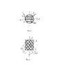
Сущность изобретения поясняется чертежами, представленными на фиг. 1-2: на фиг. 1 представлен вид спереди, на фиг. 2, - вид в продольном сечении трубопровода, проходящим через продольную ось симметрии с симметричным расположением перегородок.The essence of the invention is illustrated by the drawings shown in FIG. 1-2: in FIG. 1 is a front view, FIG. 2, is a longitudinal sectional view of the pipeline passing through the longitudinal axis of symmetry with a symmetrical arrangement of partitions.
Устройство для перемешивания среды, транспортируемой по трубопроводу, фиг. 1-2, включает смесительный элемент 1, устанавливаемый на участке трубопровода 2, состоящий из двух групп перегородок 3 и 4 соответственно пропеллерного типа; перегородки 3 и 4 ориентированы в каждой группе параллельно под углом к оси трубопровода 1 из условия формирования вращательного/-ых движения/-й частей среды относительно продольной оси трубопровода, ребра одной группы перегородок перекрещиваются с ребрами другой группы (иначе говоря, перегородки 3 и 4 не только ориентированы под углом к продольной оси трубопровода, но и имеют искривленную боковую поверхность, - перегородки закручены/изогнуты вдоль их медиан 5 под профиль пропеллера); перегородки 3 и 4 располагаются по существу симметрично относительно центра симметрии О, расположенного в середине продольной оси симметрии участка трубопровода 1 и проецируются с совмещением границ на поперечное сечение трубопровода.A device for mixing a medium transported through a pipeline, FIG. 1-2, includes a mixing element 1, installed on the section of the
Устройство для перемешивания среды, транспортируемой по трубопроводу, фиг. 1-2, предназначено для перемешивания среды, транспортируемой по трубопроводу на участке 2, в полости которого устанавливают смешивающий элемент 1; смешивающий элемент 1 служит для осуществления перемешивания среды при ее транспортировании по трубопроводу за счет энергии потока среды; две группы перегородок 3 и 4 соответственно, составляющие смешивающий элемент 1, предназначены для перемешивания среды путем разделения ими потока среды на части, при котором каждая часть потока непрерывно формируется за счет интенсивного разрушения других частей потока во всем объеме свободного пространства на участке трубопровода 2, которое происходит в результате формируемого перегородками 3 и 4 параллельно-разнонаправленного движения к противоположным стенкам трубопровода и вращения их вокруг продольной оси симметрии трубопровода.A device for mixing a medium transported through a pipeline, FIG. 1-2, is intended for mixing the medium transported through the pipeline in the
Устройство для перемешивания среды, транспортируемой по трубопроводу, фиг. 1-2, работает следующим образом.A device for mixing a medium transported through a pipeline, FIG. 1-2 works as follows.
Среда, транспортируемая по трубопроводу, при поступлении в участок трубопровода 2, фиг. 1-2, с размещенным в нем смешивающим элементом 1, подвергается перемешиванию в смешивающем элементе 1 за счет энергии потока среды. Этот процесс происходит следующим образом. Две группы перекрещивающихся ребрами параллельно-изогнутых и разнонаправленных по группам перегородок 3 и 4 соответственно в смешивающем элементе 1 разделяют поток среды на части, движение которых характеризуются параллельным и разнонаправленным движением к противоположным стенкам трубопровода, их перетоком через перегородки 3 и 4 и вращением вокруг продольной оси симметрии ![]()
![]()
Отметим, что при работе устройства имеет место проявление синергизма как при перемешивании среды, так и для режима самоочищения. Действительно, поскольку количество активных зон перемешивания, которые формируются при перекрещивании ребер перегородок 3 и 4, находится в степенной зависимости от количества последних, а в перемешивание между собой по сути в равной степени вовлекаются все части потока, то при перемешивании имеет место проявление синергетического эффекта. В то же время, изогнутость под пропеллер перегородок 3 и 4 на порядок способствует уменьшению количества точек соприкосновения ребер при их перекрещивании (сравниваем со случаем, как если бы перегородки 3 и 4 до их изгиба соприкасались по ребрам во всех точках перекрещивания), ибо при изгибе перегородок образуются треугольные зазоры 6 (треугольные просветы в поперечном сечении трубопровода). Если же бы перегородки 3 и 4 до их изгиба имели бы зазоры, то при их изгибе по профилю пропеллера, зазоры в местах перекрещивания ребер перегородок 3 и 4 еще более бы увеличились (расстояние между ребрами в местах перекрещивании перегородок изменяется по нелинейной зависимости, а количество таких участков по прежнему имеет степенную зависимость от количества перегородок 3 и 4). То есть, в обоих случаях засорение устройства уменьшается с проявлением синергизма.Note that during the operation of the device, there is a manifestation of synergy both when mixing the medium and for the self-cleaning mode. Indeed, since the number of active mixing zones that are formed when the edges of
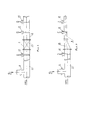
Для испытаний заявляемое устройство (смешивающий элемент 1), фиг. 1-2, было установлено на горизонтальном, прямолинейном трубопроводе с диаметром Ду 150 мм на участке 2, расположенным между участками 7 и 8 трубопровода согласно схемы, приведенной на фиг. 3. Соединения участков 2, 7 и 8 трубопровода для удобства проведения испытаний были фланцевыми. Параметры при испытаниях приводятся ниже.For testing the claimed device (mixing element 1), FIG. 1-2, was installed on a horizontal, straight pipeline with a diameter of DN 150 mm in
Среда, транспортируемая по горизонтальному трубопроводу, представляла собой водонефтяной поток, получаемый смешением потоков безводной нефти и воды, - расход воды устанавливали 2% от расхода нефти. Воду подавали по патрубку 9, расположенном на участке 7 трубопровода. Длина участка трубопровода 7 от точки ввода воды в поток безводной нефти до участка 2 перемешивания составляло 75Ду150 мм, т.е. 11,25 м. Дополнительно на трубопроводе были установлены три пробозаборные трубки 10-12, описание которых приводится ниже.The medium transported through the horizontal pipeline was a water-oil flow obtained by mixing flows of anhydrous oil and water - the water flow rate was set at 2% of the oil flow rate. Water was supplied through a
Длина смешивающего элемента 1 и участка 2 трубопровода 7 была одинаковой и составляла 180 мм; смешивающий элемент 1 состоял из двух групп перегородок 3, 4 соответственно одинаковой высоты 36 мм с одинаковым количеством в каждой группе по 10 шт. со средним углом наклона к продольной оси симметрии трубопровода α=argtg 0,8. При этом острый угол β разворота перегородок 3 и 4 относительно вертикали изменяли от 5° до 85°, то есть, практически во всем диапазоне квадранта.The length of the mixing element 1 and the
Сравнительные испытания заявляемой техники перемешивания среды, транспортируемой по трубопроводу, были проведены с использованием способа перемешивания среды, транспортируемой по трубопроводу [5] и устройства [6] для его осуществления, согласно схемы, приведенной на фиг. 4.Comparative tests of the claimed technique for mixing the medium transported through the pipeline were carried out using the method of mixing the medium transported through the pipeline [5] and the device [6] for its implementation, according to the diagram shown in FIG. four.
В качестве прототипа-устройства [6] использовался участок 13 трубопровода (переход) с эксцентричным сужением диаметра трубопровода с Ду 150 мм на Ду 65 мм длиной 180 мм, который устанавливался на трубопроводе согласно схемы, приведенной на фиг. 4. При этом в схеме фиг. 4 использовался трубопровод для испытания заявляемого устройства фиг. 3, в котором производили замену, - вместо заявляемого устройства 1 с участком 2 устанавливали устройство прототип [6], - переход 13, и меняли диаметр участка 8 трубопровода с диаметра Ду 150 на Ду 65 мм.As a prototype device [6], a
Эффективность перемешивания потока среды в трубопроводе оценивают по затраченной энергии потока, или перепаду давления на участке перемешивания, и однородности потока. При выбранных параметрах заявляемого устройства и прототипа [6], перепад давления на перемешивание, который определяли расчетным путем, для заявляемого устройства был меньше, чем для прототипа [6]. Поскольку увеличение перепада давления на перемешивания для прототипа [6] путем уменьшения диаметра сужения, как будет показано ниже, приводит к прямо противоположному результату, - ухудшению процесса перемешивания, - перепад давления по манометрам для испытуемых устройств не определяли и увеличение перепада давления для прототипа [6] еще большим уменьшением диаметра сужения не проводили.The efficiency of mixing the medium flow in the pipeline is estimated by the expended energy of the flow, or the pressure drop in the mixing section, and the homogeneity of the flow. With the selected parameters of the proposed device and prototype [6], the pressure drop for mixing, which was determined by calculation, for the proposed device was less than for the prototype [6]. Since an increase in the pressure drop for stirring for the prototype [6] by decreasing the diameter of the constriction, as will be shown below, leads to exactly the opposite result, - deterioration of the mixing process, - the pressure drop across the manometers for the tested devices was not determined and the increase in the pressure drop for the prototype [6 ] an even greater reduction in the taper diameter was not performed.
Испытуемые устройства устанавливались поочередно по схемам, приведенным на фиг. 3 и 4, на одинаковом расстоянии от точки ввода воды в поток безводной нефти, которое составляло 75Ду150 мм, т.е. 11,25 м. Смешение потоков нефти и воды до испытуемых устройств осуществлялось под воздействием турбулентности объединенного потока на прямом участке трубопровода постоянного диаметра. Вязкость безводной нефти при 20°С составляла 120 сСт, температура потока находилась в интервале 28-29°С. Заявляемое устройство испытывалось при различных углах разворота J3 перегородок 3 и 4: (β=5°, 25°, 45°, 70°, 85°, - данные сравнительных испытаний представлены соответственно в таблице, при этом режимы транспортировки среды при различных углах β повторялись, а качество перемешивания водонефтяного потока с водой оценивалось по пробам. Пробы отбирали из потока среды с разных уровней при помощи трех пробозаборных трубок 10-12, фиг. 3, фиг. 4. До и после перемешивания пробы отбирали с нижних уровней при помощи двух трубок 10-11 с изогнутым концом, обращенным навстречу водонефтяному потоку по черт. 14, ГОСТ 2517-85. Загнутые концы трубок 10-11 касались дна трубопровода. Внутренний диаметр трубок 10-11 составлял 3 мм. Назначение трубок 10-11, - оценка расслоения потока на сплошные нефтяную и водную фазы до и после перемешивания. После перемешивания пробу отбирали по диаметру трубопровода при помощи трубки щелевой 12 по черт. 15.1 ГОСТ 2517-85 с параметрами на Ду 150 мм для заявляемого устройства, фиг. 3, и с параметрами на Ду 65 мм, фиг. 4, для устройства прототип [6]. По пробе от трубки 12 определяли фактическое содержание воды в водонефтяном потоке на предмет отсутствия нарушения пропорций перемешиваемых компонентов (фаз нефти и воды), - содержание воды в водонефтяном потоке на выходе из заявляемого/прототипа [6] устройства должно быть 2%, - и оценки равномерности перемешивания путем сравнения показаний по пробам от трубок 11 и 12. Содержание воды в отобранных пробах определяли методом Дина-Старка.The devices under test were installed in turn according to the diagrams shown in FIG. 3 and 4, at the same distance from the point of introduction of water into the flow of anhydrous oil, which was 75 DN150 mm, i.e. 11.25 m. The mixing of oil and water flows up to the tested devices was carried out under the influence of turbulence of the combined flow in a straight section of a pipeline of constant diameter. The viscosity of the anhydrous oil at 20 ° C was 120 cSt, the flow temperature was in the range of 28-29 ° C. The claimed device was tested at various angles of rotation J3 of
Анализ данных таблицы показывает, что осуществление известного способа перемешивания [5] с применением устройства [6], выбранных в качестве прототипов для заявляемых решений, сопровождается нарушением технологии перемешивания по способу [5] с момента ее реализации. Это нарушение выражается в том, что продукт перемешивания (водонефтяной поток с 2% содержанием воды) характеризуется изменением содержания одного из его компонентов (2% воды) при перемешивании, а именно, уменьшением содержания воды (до 0,21%-1,35% для конкретных примеров) в водонефтяном потоке на выходе его из устройства [6]. Для установления этого факта были выбраны четыре режима транспортировки и перемешивания водонефтяного потока с 2% содержанием воды, а именно, с расходами 5, 10, 15 и 25 м3/ч с применением известной техники [5-6]. Анализ перемешивания проводили через 2, 4, 10, 20 минут с начала транспортировки водонефтяного потока. Данные этих испытаний представлены в таблице, - порядковый номер варианта испытаний соответствует указанному изменению интервала времени в порядке возрастания его значения. Испытания состояли в отборе проб из потока через трубки 10-11-12, фиг. 3, фиг. 4, и определения содержания в них воды, по которым оценивали динамику перемешивания потока и изменение компонентного состава потока. Результаты этих испытаний показывают, что содержание воды в водонефтяном потоке на выходе из устройства [6] уменьшилось с 2% до 0,21% - 1,35% (последняя 20 колонка таблицы, - анализ проб, полученных при помощи трубки 12), - меньшее значение 0,21% соответствует минимальному (5 м3/ч) расходу водонефтяного потока, а большее 1,35%, - максимальному (25 м3/ч). Объяснение этому изменению компонентного состава водонефтяного потока дают данные анализа проб, полученных из трубок 10 и 11, которые представлены в колонках 8 и 14 соответственно. Трубкой 10 в экспериментах отбирались пробы с нижних слоев водонефтяного потока на участке 7, фиг. 4, трубопровода (до его сужения с диаметра Ду 150 мм на диаметр Ду 65 мм). Как следует из данных анализа проб, отобранных при помощи трубки 10 (колонка 8 таблицы), в каждый очередной интервал времени отбора проб (2 мин, 4 мин, 10 мин, 20 мин), - содержание воды на участке 7, фиг. 4, трубопровода (до входа в устройство [6]) увеличивалось. Это увеличение с течением времени обводненности нижних слоев потока до 100% на участке 7, фиг. 4, трубопровода с диаметром Ду 150 мм при осуществлении технологии [5-6] говорит об изменении фазы в нижних слоях потока с нефтяной на водную. Содержание же воды в нижних слоях потока на участке 8, фиг. 4, трубопровода после устройства [6] при каждом значении расхода потока практически не менялось и оставалось относительно не высоким, как следует данных анализа проб из трубки 11 с нижних слоев на участке 8, фиг. 4, трубопровода, - колонка 14 таблицы. Такая динамика распределения воды в потоке говорит о том, что именно на участке 7, фиг. 4, трубопровода с диаметром Ду 150 мм часть воды отделяется от водонефтяного потока, оседая на дно, и не поступает в участок 8, фиг. 4, трубопровода, представляющий его сужение 13 с Ду 150 мм на Ду 65 мм. Этим и объясняется нарушение технологии перемешивания с применением известной техники - прототип [5-6]. Но, согласно технологии разделения многофазных потоков, этого следовало ожидать, поскольку применение в трубопроводе перехода с большего на меньший диаметр применяется в динамических отстойниках именно для обеспечения процесса разделения потока многофазной среды на компоненты. В нашем случае в технике - прототип [5-6] сужение трубопровода превращает участок 7, фиг. 4, трубопровода до сужения в карман. В нем происходит разделение среды на фазы при ее расходе от 5 до 25 м3/ч. Поскольку, в технике [5-6], в отличие от техники разделения многофазной среды в динамических отстойниках, отсутствует раздельный отвод фаз, то рано или поздно участок 7, фиг. 4, трубопровода заполнится до критического уровня водой. Выше этого уровня сужение 13 между участками 7 и 8, фиг. 4, трубопровода не сможет задерживать отделяющуюся на участке 7 воду. Вода в полном объеме начнет поступать в участок 8 трубопровода с сужением 13, фиг. 4. Однако это не меняет общей картины перемешивания, - нарушение перемешивания вдоль трубопровода при этом не устраняется, поскольку объем воды, отделившейся от водонефтяного потока до критического уровня, так и останется в трубопроводе на участке 7, фиг. 4, и не поступит в участок 8, фиг. 4, на перемешивание с нефтью. Техника перемешивания [5-6] не ограничивает длину участка 7, фиг. 4, трубопровода с большим диаметром, а также диаметр сужения 13, фиг. 4, трубопровода. Таким образом, чем больше будет длина такого участка и чем меньше будет диаметр сужения трубопровода, тем больше будет объем кармана им образуемый, тем больший объем задерживаемой им воды и других включений будет исключено из цикла перемешивания, тем больше будет неоднородность потока вдоль трубопровода. И это будет происходить вопреки технологии перемешивания, когда при увеличении интенсивности перемешивания однородность потока не возрастает, а ухудшается, причем, с проявлением синергизма, поскольку перепад давления при уменьшении диаметра будет возрастать в квадратичной зависимости (поскольку перепад давления пропорционален квадрату скорости потока). Следует также отметить, что участок 7, фиг. 4, трубопровода при реализации прототипа [5-6] оказывается подвержен быстрому засорению тяжелыми частицами, присутствующими в нефти (песок, глина, соли другие мехпримеси), - катализатором по ряду параметров служит скапливающаяся на нем сплошная водная фаза, - например, низкая вязкость.Analysis of the data in the table shows that the implementation of the known mixing method [5] using the device [6], selected as prototypes for the proposed solutions, is accompanied by a violation of the mixing technology according to the method [5] from the moment of its implementation. This violation is expressed in the fact that the mixing product (water-oil flow with 2% water content) is characterized by a change in the content of one of its components (2% water) during mixing, namely, a decrease in the water content (up to 0.21% -1.35% for specific examples) in the water-oil flow at its outlet from the device [6]. To establish this fact, four modes of transportation and mixing of a water-oil flow with 2% water content were chosen, namely, with a flow rate of 5, 10, 15 and 25 m 3 / h using known technology [5-6]. The analysis of mixing was carried out after 2, 4, 10, 20 minutes from the beginning of the transportation of the water-oil flow. The data of these tests are presented in the table, - the serial number of the test variant corresponds to the indicated change in the time interval in ascending order of its value. The tests consisted of sampling the flow through tubes 10-11-12, FIG. 3, fig. 4, and determination of the water content in them, by which the dynamics of flow mixing and the change in the component composition of the flow were estimated. The results of these tests show that the water content in the water-oil flow at the outlet of the device [6] decreased from 2% to 0.21% - 1.35% (the last 20 column of the table, - analysis of samples obtained using tube 12), - a lower value of 0.21% corresponds to the minimum (5 m 3 / h) flow rate of the water-oil flow, and a higher value of 1.35% corresponds to the maximum (25 m 3 / h). An explanation for this change in the component composition of the water-oil flow is provided by the analysis data of samples obtained from
Применение заявляемых решений для перемешивания среды, транспортируемой по трубопроводу, в отличие от прототипов [5-6], позволяет исключить возникновение кармана в трубопроводе и обеспечить однородность перемешивания вдоль трубопровода. Согласно данным таблицы, колонки 3-7, на участке 7, фиг. 3, трубопровода до заявляемого устройства (по ходу потока) имеет место расслоение водонефтяного потока под воздействием гравитации, - содержание воды в нижних слоях значительно выше 2%. Однако содержание воды в водонефтяном потоке при этом после перемешивания на участке трубопровода 8, фиг. 3, не изменяется и составляет 2%, - колонки 15-19. Это говорит об отсутствии нарушения равномерного распределения воды вдоль трубопровода до и после заявляемого устройства, то есть, об однородности перемешивания водонефтяного потока вдоль трубопровода. Применение в заявляемом устройстве перегородок, которые формируют вращение водонефтяного потока вокруг продольной оси симметрии трубопровода путем разделения потока на параллельно разнонаправленные части, и одновременно формируют разделение потока на части за счет формирования ими вращения водонефтяного потока вокруг продольной оси симметрии трубопровода, обеспечивает качественно иное перемешивание. Во-первых, за счет формирования каждой части потока на ограниченном участке трубопровода, - в пределах размеров смесительного элемента, - за счет частей потока с различных уровней благодаря вращению потока и разнонаправленности всех частей потока. При таком формировании каждой части потока действительно происходит выравнивание концентрации воды (компонентов) в потоке поперечном сечении трубопровода. Во-вторых, за счет формирования активных зон локального перемешивания вблизи ребер перегородок и мест (участков) их перекрещивания, причем с проявлением синергизма, поскольку количество участков перекрещивания ребер имеет степенную зависимость от количества перегородок в смешивающем элементе. В-третьих, за счет того, что вращение потока снижает относительную скорость перемещения капель воды в потоке, обеспечивает тангенциальное перемещение капель вместе с нефтью со скоростью, значительно превышающей скорость осаждения капель и, тем самым, делает гравитационную составляющую не существенной, то есть, не влияющей на перемешивание. При этом направленность частей потока от стенки трубопровода преимущественно к центральным областям потока переносит водную фазу от стенок трубопровода и тем препятствует увеличению концентрации воды вблизи них под воздействием вращения потока.The use of the proposed solutions for mixing the medium transported through the pipeline, in contrast to the prototypes [5-6], eliminates the occurrence of a pocket in the pipeline and ensures the homogeneity of mixing along the pipeline. According to the table, columns 3-7, in section 7, FIG. 3, the pipeline to the claimed device (along the flow) is stratified by the oil-water flow under the influence of gravity - the water content in the lower layers is significantly higher than 2%. However, the water content in the water-oil flow, after mixing in the
Таким образом, одновременное формирование вращения потока и разделения потока на параллельно-разнонаправленные части обеспечивает равномерность концентрации капель воды в поперечном сечении. В свою очередь, равномерность распределения водной фазы в потоке поперечном сечении трубопровода гарантирует 2% распределение ее в потоке вдоль трубопровода, то есть, однородность потока вдоль трубопровода. Равномерность распределения при перемешивании одного из компонентов, в нашем случае воды, означает, что и другие компоненты будут более равномерно распределяться в потоке. Значит, заявляемое устройство будет наименее подвержено засорению. Следовательно, заявляемые решения более предпочтительны для перемешивания, нежели прототипы [5-6].Thus, the simultaneous formation of the rotation of the flow and the division of the flow into parallel-multidirectional parts ensures the uniformity of the concentration of water droplets in the cross section. In turn, the uniformity of distribution of the water phase in the flow of the cross-section of the pipeline guarantees 2% distribution of it in the flow along the pipeline, that is, the uniformity of the flow along the pipeline. The uniformity of distribution during mixing of one of the components, in our case water, means that other components will be more evenly distributed in the flow. This means that the claimed device will be the least susceptible to clogging. Therefore, the proposed solutions are more preferable for mixing than the prototypes [5-6].
Отметим, что для профиля перегородок, когда не примыкающие к стенке трубопровода ребра перегородок в заявляемом устройстве имеют наклон друг к другу, а образуемое ими сужение трубопровода на участке размещения смешивающего элемента идентично случаю, когда ребра параллельны (это условие профиля перегородок эквивалентно вышеприведенному правилу (А)), смешивающий элемент оказывается наименее подвержен засорению. Действительно, в этом случае инградиенты, перемещающиеся по боковой поверхности перегородок непрерывно сходят с этой поверхности в силу уменьшения ее площади. Такая динамика движения потока обеспечивает еще более равномерное объемное перемешивание. Это подтверждают также данные проб с нижних слоев трубопровода, - в таблице они не приведены, - содержание воды в них уменьшалась на 17-38% и приближалось к 2%.Note that for the profile of the partitions, when the ribs of the partitions not adjacent to the wall of the pipeline in the claimed device are inclined towards each other, and the narrowing of the pipeline formed by them at the site of the mixing element is identical to the case when the ribs are parallel (this condition of the profile of the partitions is equivalent to the above rule (A )), the mixing element is the least susceptible to clogging. Indeed, in this case, the ingredients moving along the lateral surface of the partitions continuously descend from this surface due to a decrease in its area. This flow dynamics provides an even more uniform volumetric mixing. This is also confirmed by the data of samples from the lower layers of the pipeline - they are not shown in the table - the water content in them decreased by 17-38% and approached 2%.
Таким образом, данные сравнительных испытаний подтверждают эффективность применения заявляемых решений по сравнению с решениями - прототип [5-6], - разделение потока на части в разнонаправленных перегородках из условия обеспечения пропорциональности распределения в поперечном и продольном направлениях на входе в смешивающий элемент позволит обеспечить более равномерное распределение поля скоростей потока как вдоль трубопровода, так и в поперечном его сечении, и тем повысить однородность при перемешивании и снизить потери напора потока, повысить качество перемешивания.Thus, the data of comparative tests confirm the effectiveness of the application of the proposed solutions in comparison with the solutions - prototype [5-6], - dividing the flow into parts in multidirectional partitions from the condition of ensuring proportional distribution in the transverse and longitudinal directions at the entrance to the mixing element will provide a more uniform distribution of the flow velocity field both along the pipeline and in its cross-section, and thus increase the homogeneity during mixing and reduce the flow head loss, improve the mixing quality.
Заявляемый способ перемешивания среды, транспортируемой по трубопроводу и устройство для его осуществления промышленно применимы, - для реализации заявляемой технологии устройства для ее осуществления не сложны в изготовлении и поэтому эта технология перемешивания может быть включена в любой технологический процесс, где необходимо перемешивание потоков с различной вязкостью, плотностью.The inventive method of mixing the medium transported through the pipeline and the device for its implementation are industrially applicable - for the implementation of the inventive technology, the devices for its implementation are not difficult to manufacture and therefore this mixing technology can be included in any technological process where it is necessary to mix flows with different viscosities, density.
Источники информации.Sources of information.
1. Способ для перемешивания среды, транспортируемой по трубопроводу. / Патент СН №642564.1. A method for mixing a medium transported through a pipeline. / Patent SN No. 642564.
2. Устройство для перемешивания среды, транспортируемой по трубопроводу. / Патент СН №642564.2. A device for mixing the medium transported through the pipeline. / Patent SN No. 642564.
3. Способ для перемешивания среды, транспортируемой по трубопроводу. / Патент на изобретение RU №2470702.3. A method for mixing a medium transported through a pipeline. / Patent for invention RU No. 2470702.
4. Устройство для перемешивания среды, транспортируемой по трубопроводу. / Патент на изобретение RU №2470702.4. A device for mixing the medium transported through the pipeline. / Patent for invention RU No. 2470702.
5. Способ для перемешивания среды, транспортируемой по трубопроводу./ ГОСТ Р 8.880-2015, п.п. 4.1.1, 4.1.2.3, п. 6.3, п. 6.4, п.п. 2.13.1.2, 2.13.1.4, 2.13.1.7, черт. А.2.5. Method for mixing the medium transported through the pipeline. / GOST R 8.880-2015, p. 4.1.1, 4.1.2.3, clause 6.3, clause 6.4, clauses 2.13.1.2, 2.13.1.4, 2.13.1.7, damn. A.2.
6. Устройство для перемешивания среды, транспортируемой по трубопроводу./ ГОСТ Р 8.880-2015, п.п. 4.1.1, 4.1.2.3, п. 6.3, п. 6.4, п.п. 2.13.1.2, 2.13.1.4, 2.13.1.7, черт.А.2.6. Device for mixing the medium transported through the pipeline. / GOST R 8.880-2015, p. 4.1.1, 4.1.2.3, clause 6.3, clause 6.4, clauses 2.13.1.2, 2.13.1.4, 2.13.1.7, drawing A.2.
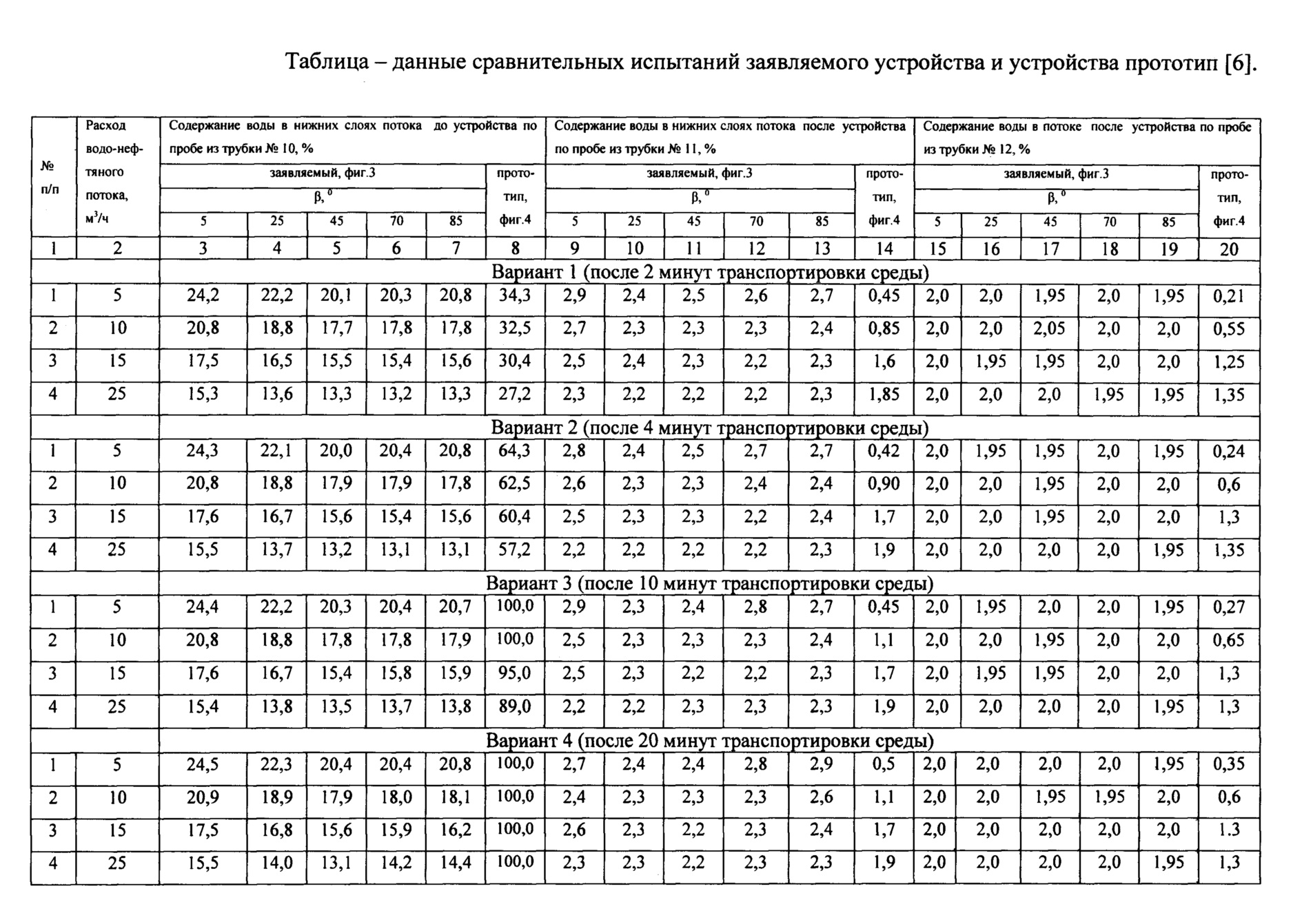
Claims (2)
Priority Applications (1)
| Application Number | Priority Date | Filing Date | Title |
|---|---|---|---|
| RU2019130347A RU2744373C1 (en) | 2019-09-24 | 2019-09-24 | Method for mixing medium transported through pipeline and device for carrying out said method |
Applications Claiming Priority (1)
| Application Number | Priority Date | Filing Date | Title |
|---|---|---|---|
| RU2019130347A RU2744373C1 (en) | 2019-09-24 | 2019-09-24 | Method for mixing medium transported through pipeline and device for carrying out said method |
Publications (1)
| Publication Number | Publication Date |
|---|---|
| RU2744373C1 true RU2744373C1 (en) | 2021-03-05 |
Family
ID=74857768
Family Applications (1)
| Application Number | Title | Priority Date | Filing Date |
|---|---|---|---|
| RU2019130347A RU2744373C1 (en) | 2019-09-24 | 2019-09-24 | Method for mixing medium transported through pipeline and device for carrying out said method |
Country Status (1)
| Country | Link |
|---|---|
| RU (1) | RU2744373C1 (en) |
Cited By (1)
| Publication number | Priority date | Publication date | Assignee | Title |
|---|---|---|---|---|
| RU2794080C1 (en) * | 2022-02-18 | 2023-04-11 | Ильдар Ринатович Вальшин | Method for mixing a medium transported through a pipeline and a device for its implementation |
Citations (5)
| Publication number | Priority date | Publication date | Assignee | Title |
|---|---|---|---|---|
| US3785620A (en) * | 1971-04-29 | 1974-01-15 | Sulzer Ag | Mixing apparatus and method |
| CH642564A5 (en) * | 1979-10-26 | 1984-04-30 | Sulzer Ag | STATIC MIXING DEVICE. |
| RU2091146C1 (en) * | 1993-10-05 | 1997-09-27 | Зульцер Хемтех Аг | Apparatus for homogenizing high-viscosity media |
| EP0856353A1 (en) * | 1997-01-29 | 1998-08-05 | Sulzer Chemtech AG | Module for a static mixer for a resident time critical plastic flowable mixture |
| RU2470702C2 (en) * | 2007-06-22 | 2012-12-27 | Зульцер Хемтех Аг | Static mixer |
-
2019
- 2019-09-24 RU RU2019130347A patent/RU2744373C1/en active
Patent Citations (5)
| Publication number | Priority date | Publication date | Assignee | Title |
|---|---|---|---|---|
| US3785620A (en) * | 1971-04-29 | 1974-01-15 | Sulzer Ag | Mixing apparatus and method |
| CH642564A5 (en) * | 1979-10-26 | 1984-04-30 | Sulzer Ag | STATIC MIXING DEVICE. |
| RU2091146C1 (en) * | 1993-10-05 | 1997-09-27 | Зульцер Хемтех Аг | Apparatus for homogenizing high-viscosity media |
| EP0856353A1 (en) * | 1997-01-29 | 1998-08-05 | Sulzer Chemtech AG | Module for a static mixer for a resident time critical plastic flowable mixture |
| RU2470702C2 (en) * | 2007-06-22 | 2012-12-27 | Зульцер Хемтех Аг | Static mixer |
Cited By (1)
| Publication number | Priority date | Publication date | Assignee | Title |
|---|---|---|---|---|
| RU2794080C1 (en) * | 2022-02-18 | 2023-04-11 | Ильдар Ринатович Вальшин | Method for mixing a medium transported through a pipeline and a device for its implementation |
Similar Documents
| Publication | Publication Date | Title |
|---|---|---|
| Liu et al. | Separation performance of hydrocyclones with medium rearrangement internals | |
| Rocha et al. | Numerical and experimental study of an axially induced swirling pipe flow | |
| Shao et al. | Flow regimes for adiabatic gas–liquid flow in microchannels | |
| Trallero et al. | A study of oil/water flow patterns in horizontal pipes | |
| Vaseleski et al. | Drag reduction in the turbulent flow of fiber suspensions | |
| CA2519011C (en) | Helical piping | |
| CN102423549B (en) | Dewatering apparatus and oil-water cyclone separator of pipe type distributor oil-water separator | |
| Tan et al. | Experimental study of the factors affecting the flow pattern transition in horizontal oil–water flow | |
| Dehkordi et al. | The hydrodynamic behavior of high viscous oil-water flow through horizontal pipe undergoing sudden expansion—CFD study and experimental validation | |
| Sunder Raj et al. | Liquid‐Liquid Stratified Flow through Horizontal Conduits | |
| CN102251765A (en) | Axial type inlet oil-water cyclone separator | |
| CN106391335A (en) | Spiral piece flow guiding type phase separation device | |
| Catrawedarma et al. | Hydrodynamic behaviors of air–water two-phase flow during the water lifting in a bubble generator type of airlift pump system | |
| RU2744373C1 (en) | Method for mixing medium transported through pipeline and device for carrying out said method | |
| EP4715030A1 (en) | Pipeline-type pre-water-separation system for oilfield produced fluid | |
| Boogar et al. | The effects of viscosity, surface tension, and flow rate on gasoil-water flow pattern in microchannels | |
| Scott et al. | Transport of solids by gas‐liquid mixtures in horizontal pipes | |
| Lan et al. | Enhancing gas-liquid mixing effect in pipelines: Experimental and numerical investigations of blind tee and traditional elbow | |
| US4619771A (en) | Technique for increased retention time in oil field settling tanks | |
| Yin et al. | Influence of aqueous foam on gas–liquid flow development of hilly-terrain wet gas pipeline with surfactant injection | |
| Sokhal et al. | An experimental investigation of heterogeneous injection of biopolymer (guar gum) on the flow patterns and drag reduction percentage for two phase (water-oil mixture) flow | |
| Deka et al. | Flow pattern shifting and drag reduction in oil-water flow in pipe | |
| Seyer et al. | Drag reduction in large tubes and the behavior of annular films of drag reducing fluids | |
| Powers | Analysis off Gravity Separation in Freewater Knockouts | |
| Edomwonyi-Out et al. | Influence of drag reducing agents on interfacial wave characteristics in horizontal oil-water flow |