RU2738985C2 - Clamping device for connection of two pipes with controlled angular positioning - Google Patents
Clamping device for connection of two pipes with controlled angular positioning Download PDFInfo
- Publication number
- RU2738985C2 RU2738985C2 RU2017134103A RU2017134103A RU2738985C2 RU 2738985 C2 RU2738985 C2 RU 2738985C2 RU 2017134103 A RU2017134103 A RU 2017134103A RU 2017134103 A RU2017134103 A RU 2017134103A RU 2738985 C2 RU2738985 C2 RU 2738985C2
- Authority
- RU
- Russia
- Prior art keywords
- pipe
- backing ring
- locking tab
- pipes
- locking
- Prior art date
Links
Images


Classifications
-
- F—MECHANICAL ENGINEERING; LIGHTING; HEATING; WEAPONS; BLASTING
- F16—ENGINEERING ELEMENTS AND UNITS; GENERAL MEASURES FOR PRODUCING AND MAINTAINING EFFECTIVE FUNCTIONING OF MACHINES OR INSTALLATIONS; THERMAL INSULATION IN GENERAL
- F16L—PIPES; JOINTS OR FITTINGS FOR PIPES; SUPPORTS FOR PIPES, CABLES OR PROTECTIVE TUBING; MEANS FOR THERMAL INSULATION IN GENERAL
- F16L19/00—Joints in which sealing surfaces are pressed together by means of a member, e.g. a swivel nut, screwed on or into one of the joint parts
- F16L19/02—Pipe ends provided with collars or flanges, integral with the pipe or not, pressed together by a screwed member
- F16L19/0206—Pipe ends provided with collars or flanges, integral with the pipe or not, pressed together by a screwed member the collar not being integral with the pipe
-
- F—MECHANICAL ENGINEERING; LIGHTING; HEATING; WEAPONS; BLASTING
- F16—ENGINEERING ELEMENTS AND UNITS; GENERAL MEASURES FOR PRODUCING AND MAINTAINING EFFECTIVE FUNCTIONING OF MACHINES OR INSTALLATIONS; THERMAL INSULATION IN GENERAL
- F16L—PIPES; JOINTS OR FITTINGS FOR PIPES; SUPPORTS FOR PIPES, CABLES OR PROTECTIVE TUBING; MEANS FOR THERMAL INSULATION IN GENERAL
- F16L21/00—Joints with sleeve or socket
- F16L21/08—Joints with sleeve or socket with additional locking means
-
- F—MECHANICAL ENGINEERING; LIGHTING; HEATING; WEAPONS; BLASTING
- F16—ENGINEERING ELEMENTS AND UNITS; GENERAL MEASURES FOR PRODUCING AND MAINTAINING EFFECTIVE FUNCTIONING OF MACHINES OR INSTALLATIONS; THERMAL INSULATION IN GENERAL
- F16L—PIPES; JOINTS OR FITTINGS FOR PIPES; SUPPORTS FOR PIPES, CABLES OR PROTECTIVE TUBING; MEANS FOR THERMAL INSULATION IN GENERAL
- F16L21/00—Joints with sleeve or socket
- F16L21/06—Joints with sleeve or socket with a divided sleeve or ring clamping around the pipe-ends
- F16L21/065—Joints with sleeve or socket with a divided sleeve or ring clamping around the pipe-ends tightened by tangentially-arranged threaded pins
-
- F—MECHANICAL ENGINEERING; LIGHTING; HEATING; WEAPONS; BLASTING
- F16—ENGINEERING ELEMENTS AND UNITS; GENERAL MEASURES FOR PRODUCING AND MAINTAINING EFFECTIVE FUNCTIONING OF MACHINES OR INSTALLATIONS; THERMAL INSULATION IN GENERAL
- F16L—PIPES; JOINTS OR FITTINGS FOR PIPES; SUPPORTS FOR PIPES, CABLES OR PROTECTIVE TUBING; MEANS FOR THERMAL INSULATION IN GENERAL
- F16L21/00—Joints with sleeve or socket
-
- F—MECHANICAL ENGINEERING; LIGHTING; HEATING; WEAPONS; BLASTING
- F16—ENGINEERING ELEMENTS AND UNITS; GENERAL MEASURES FOR PRODUCING AND MAINTAINING EFFECTIVE FUNCTIONING OF MACHINES OR INSTALLATIONS; THERMAL INSULATION IN GENERAL
- F16L—PIPES; JOINTS OR FITTINGS FOR PIPES; SUPPORTS FOR PIPES, CABLES OR PROTECTIVE TUBING; MEANS FOR THERMAL INSULATION IN GENERAL
- F16L23/00—Flanged joints
- F16L23/04—Flanged joints the flanges being connected by members tensioned in the radial plane
- F16L23/08—Flanged joints the flanges being connected by members tensioned in the radial plane connection by tangentially arranged pin and nut
-
- F—MECHANICAL ENGINEERING; LIGHTING; HEATING; WEAPONS; BLASTING
- F16—ENGINEERING ELEMENTS AND UNITS; GENERAL MEASURES FOR PRODUCING AND MAINTAINING EFFECTIVE FUNCTIONING OF MACHINES OR INSTALLATIONS; THERMAL INSULATION IN GENERAL
- F16L—PIPES; JOINTS OR FITTINGS FOR PIPES; SUPPORTS FOR PIPES, CABLES OR PROTECTIVE TUBING; MEANS FOR THERMAL INSULATION IN GENERAL
- F16L23/00—Flanged joints
- F16L23/16—Flanged joints characterised by the sealing means
- F16L23/18—Flanged joints characterised by the sealing means the sealing means being rings
- F16L23/20—Flanged joints characterised by the sealing means the sealing means being rings made exclusively of metal
-
- F—MECHANICAL ENGINEERING; LIGHTING; HEATING; WEAPONS; BLASTING
- F16—ENGINEERING ELEMENTS AND UNITS; GENERAL MEASURES FOR PRODUCING AND MAINTAINING EFFECTIVE FUNCTIONING OF MACHINES OR INSTALLATIONS; THERMAL INSULATION IN GENERAL
- F16L—PIPES; JOINTS OR FITTINGS FOR PIPES; SUPPORTS FOR PIPES, CABLES OR PROTECTIVE TUBING; MEANS FOR THERMAL INSULATION IN GENERAL
- F16L23/00—Flanged joints
- F16L23/16—Flanged joints characterised by the sealing means
- F16L23/162—Flanged joints characterised by the sealing means the pipe ends abutting each other
Landscapes
- Engineering & Computer Science (AREA)
- General Engineering & Computer Science (AREA)
- Mechanical Engineering (AREA)
- Clamps And Clips (AREA)
- Quick-Acting Or Multi-Walled Pipe Joints (AREA)
- Mutual Connection Of Rods And Tubes (AREA)
- Gasket Seals (AREA)
- Joints With Sleeves (AREA)
Abstract
Description
Изобретение относится к устройству для соединения вместе первой трубы и второй трубы, при этом устройство содержит зажимной хомут, выполненный с возможностью стягивания вокруг примыкающих друг к другу концов двух труб, и подкладное кольцо, прикрепленное к зажимному хомуту крепежным средством.The invention relates to a device for joining together a first pipe and a second pipe, the device comprising a clamping yoke capable of being pulled together around the adjacent ends of two pipes and a backing ring attached to the clamping clamp by fastening means.
Зажимное устройство такого типа известно из европейского патента EP 1451498. В этом патенте обращенные друг к другу концы труб имеют опорные поверхности, которые выступают относительно цилиндрических внешних поверхностей упомянутых труб. Зажимной хомут имеет зажимной бандаж секции, которая может иметь, по сути, V-образную или U-образную форму, так что плечи, образованные этой секцией, опираются, соответственно, на опорную поверхность первой трубы и опорную поверхность второй трубы. Вследствие этого затягивание хомута приводит к прижиманию двух труб друг к другу. V-образная форма секции предпочтительна потому, что при затягивании хомута она обеспечивает перемещение труб навстречу друг другу.A clamping device of this type is known from EP 1451498. In this patent, the facing ends of the pipes have support surfaces that project relative to the cylindrical outer surfaces of said pipes. The clamping yoke has a clamping band of the section, which can be substantially V-shaped or U-shaped, so that the arms formed by this section rest, respectively, on the supporting surface of the first pipe and the supporting surface of the second pipe. As a consequence, tightening the clamp causes the two pipes to be pressed against each other. The V-shape of the section is preferable because when the clamp is tightened, it allows the pipes to move towards each other.
Например, средство для затягивания бандажа может представлять собой систему гайка-болт. В связи с этим концы бандажа могут выступать вверх, чтобы таким образом формировать опорные язычки, каждый из которых имеет отверстие, через которое может быть вставлен болт. За одним из язычков расположена гайка, так что вращение болта приводит к затягиванию хомута. Однако могут быть обеспечены другие средства затягивания, например, работающие по типу зацепления крюком, в частности, содержащие крюк, отстоящий от бандажа, и выступ, также отстоящий от бандажа, при этом крюк заводят за выступ, чтобы удерживать хомут в затянутом состоянии.For example, the means for tightening the band can be a nut-bolt system. In this regard, the ends of the band can protrude upwardly to thereby form support tongues, each of which has a hole through which a bolt can be inserted. A nut is located behind one of the tabs, so that rotation of the bolt tightens the clamp. However, other means of tightening can be provided, for example, operating in the type of hook engagement, in particular comprising a hook spaced from the band and a projection also spaced from the band, the hook being pulled over the projection to keep the clamp tightened.
Подкладное кольцо зажимного устройства может, в частности, выполнять функцию уплотнения соединения двух труб, имея для этого уплотнительный участок, который при затягивании устройства на трубах зажимается между двумя уплотняющими поверхностями, принадлежащими соответственно первой трубе и второй трубе.The backing ring of the clamping device can, in particular, perform the function of sealing the connection between two pipes, for this purpose having a sealing section which, when the device is tightened on the pipes, is clamped between two sealing surfaces, respectively, of the first pipe and the second pipe.
В некоторых применениях также желательно гарантировать, что зажимное устройство займет некоторое угловое положение относительно первой трубы, в частности, для регулировки положения опорных язычков и болта и оптимизации пространства, занимаемого устройством, или же облегчения доступа оператора к зажимному устройству при его сборке или разборке.In some applications, it is also desirable to ensure that the clamping device takes a certain angular position relative to the first pipe, in particular to adjust the position of the support tabs and bolt and optimize the space occupied by the device, or to facilitate operator access to the clamping device during assembly or disassembly.
В патентном документе WO 2016034820 описано другое зажимное устройство для соединения вместе двух труб, содержащее зажимной хомут и удерживающий язычок. Удерживающий язычок имеет крепежную часть на зажимающем бандаже хомута и дополнительную часть, при этом упомянутый удерживающий язычок выполнен с возможностью прикрепления к первой трубе. Такой удерживающий язычок обеспечивает сохранение углового положения зажимного хомута относительно первой трубы. Однако он занимает дополнительное пространство снаружи первой трубы и требует для соединения с первой трубой дополнительного этапа, например, этапа сварки, что удлиняет процесс соединения труб вместе.Patent document WO 2016034820 describes another clamping device for joining two pipes together, comprising a clamping collar and a retaining tab. The retaining tab has a fastening part on the clamping band of the collar and an additional part, said retaining tab being adapted to be attached to the first pipe. Such a retaining tongue maintains the angular position of the clamp with respect to the first pipe. However, it takes up additional space outside the first pipe and requires an additional step, such as a welding step, to connect to the first pipe, which lengthens the process of joining the pipes together.
С целью устранения вышеупомянутых недостатков имеется необходимость в новом типе устройства для соединения и зажима, и, в частности, для регулировки углового положения зажимного устройства относительно первой трубы, которое было бы простым, прочным и компактным.In order to eliminate the aforementioned disadvantages, there is a need for a new type of connecting and clamping device, and in particular for adjusting the angular position of the clamping device relative to the first pipe, which is simple, robust and compact.
Эта задача решена благодаря использованию подкладного кольца со стопорным элементом, предназначенным для взаимодействия с позиционирующим элементом первой трубы, чтобы предотвращать проворачивание подкладного кольца относительно первой трубы.This problem is solved by the use of a backing ring with a locking element designed to interact with the positioning element of the first pipe in order to prevent the backing ring from rotating relative to the first pipe.
Таким образом, взаимодействие между стопорным элементом и позиционирующим элементом гарантирует, что зажимное устройство и первая труба находятся в надлежащем угловом положении относительно друг друга. Такое угловое положение может быть задано соответствующими положениями стопорного элемента на подкладном кольце и позиционирующего элемента на первой трубе. Кроме того, взаимодействие между стопорным элементом и позиционирующим элементом предназначено для исключения необходимости использования третьего элемента, такого как удерживающий язычок, тем самым ограничивая сложность зажимного устройства. Более того, в виду того, что угловое положение регулируется подкладным кольцом, взаимодействующим с первой трубой, не требуется дополнительного пространства снаружи упомянутой трубы, в отличие от системы, предложенной в документе WO 2016034820.Thus, the interaction between the stopper element and the positioning element ensures that the clamping device and the first tube are in the correct angular position relative to each other. This angular position can be determined by the respective positions of the stopper on the backing ring and the positioning element on the first tube. In addition, the interaction between the locking member and the positioning member is designed to eliminate the need for a third member such as a retaining tab, thereby limiting the complexity of the clamping device. Moreover, in view of the fact that the angular position is adjusted by a backing ring cooperating with the first pipe, no additional space is required outside the said pipe, in contrast to the system proposed in WO 2016034820.
В одном из примеров вышеупомянутое подкладное кольцо может быть такого же типа, что и подкладные кольца, описанные в патентных документах EP 1451498, WO 2012013891 или FR 3048468. В дополнение к описанным выше характеристикам изобретения, подкладное кольцо может иметь некоторые или все характеристики, описанные в упомянутых патентных документах.In one example, the aforementioned backing ring may be of the same type as the backing rings described in EP 1451498, WO 2012013891 or FR 3048468. In addition to the characteristics of the invention described above, the backing ring may have some or all of the characteristics described in the mentioned patent documents.
Кроме того, стопорный элемент расположен, по существу, на участке подкладного кольца с наименьшим диаметром (т.е. на участке, имеющем наименьший диаметр), тем самым дополнительно уменьшая объем занимаемого пространства. Понятие «по существу» используется для обозначения того, что стопорный элемент расположен вблизи участка подкладного кольца с наименьшим диаметром, т.е. на расстоянии от участка подкладного кольца с наименьшим диаметром, которое не превышает 40% осевой длины подкладного кольца, предпочтительно 30%, более предпочтительно 15%, более предпочтительно 10%, еще более предпочтительно 5%.In addition, the stopper is located substantially in the smallest diameter portion of the washer (i.e., the smallest diameter portion), thereby further reducing the amount of space required. Substantially used to mean that the stopper is located close to the smallest diameter portion of the washer, i.e. at a distance from the portion of the backing ring with the smallest diameter that does not exceed 40% of the axial length of the backing ring, preferably 30%, more preferably 15%, more preferably 10%, even more preferably 5%.
Дополнительно, стопорный элемент содержит стопорный язычок, предназначенный для вхождения в позиционирующий элемент первой трубы. Таким образом, взаимодействие между стопорным элементом и позиционирующим элементом представляет собой простое, механическое и геометрическое взаимодействие, не требующее какой-либо конкретной операции крепления.Additionally, the stop member comprises a stop tab for engaging the positioning member of the first tube. Thus, the interaction between the locking element and the positioning element is a simple, mechanical and geometric interaction that does not require any specific fastening operation.
Кроме того, подкладное кольцо, как правило, выполняют из металла путем штамповки, вырезания и сгибания. При изготовлении подкладного кольца легко изготовить на нем выступ для формирования стопорного язычка. К тому же, стопорный язычок может быть выполнен за одно целое с подкладным кольцом.In addition, the backing ring is usually made of metal by stamping, cutting and folding. When making a backing ring, it is easy to make a protrusion on it to form a locking tab. In addition, the locking tab can be made in one piece with the washer ring.
Дополнительно, стопорный язычок выступает радиально внутрь подкладного кольца. Понятие «внутрь» означает направление к оси, вокруг которой расположено подкладное кольцо. В целом, если не указано иное, понятия «внутрь», «наружу» или же «внутренний» и «наружный» используются относительно радиального направления, так что внутренний участок элемента ближе к оси подкладного кольца в радиальном направлении, чем наружный участок этого же элемента. Тот факт, что стопорный язычок проходит радиально внутрь подкладного кольца, дополнительно ограничивает занимаемое пространство.Additionally, the locking tab projects radially into the interior of the washer. Inward means the direction towards the axis around which the washer is located. In general, unless otherwise indicated, the terms "inward", "outward" or "inward" and "outward" are used relative to the radial direction, so that the inner portion of the element is closer to the axis of the backing ring in the radial direction than the outer portion of the same element ... The fact that the locking tab extends radially inside the washer further limits the space required.
Дополнительно, стопорный язычок проходит, по существу, от участка подкладного кольца, имеющего наименьший диаметр. В частности, когда обращенные друг к другу концы труб имеют опорные поверхности, которые проходят относительно цилиндрических внешних поверхностей упомянутых труб, подкладное кольцо предпочтительно имеет форму усеченного конуса.Additionally, the locking tab extends substantially from the portion of the backing ring having the smallest diameter. In particular, when the mutually facing pipe ends have bearing surfaces that extend relative to the cylindrical outer surfaces of said pipes, the backing ring is preferably frusto-conical.
Таким образом, стопорный язычок выступает радиально внутрь относительно остальной части подкладного кольца. Альтернативно или дополнительно, стопорный язычок может выступать вдоль оси и/или радиально за пределы остальной части подкладного кольца.Thus, the locking tab projects radially inwardly relative to the rest of the washer. Alternatively or additionally, the locking tab can project axially and / or radially beyond the rest of the backing ring.
Кроме того, стопорный элемент, в частности стопорный язычок, может быть сформирован на краю подкладного кольца. In addition, a locking element, in particular a locking tab, can be formed at the edge of the washer.
Дополнительно, когда устройство монтируют на первой трубе, стопорный язычок выступает в направлении края первой трубы, т.е. конца первой трубы, который должен упираться торцом во вторую трубу.Additionally, when the device is mounted on the first pipe, the locking tab protrudes towards the edge of the first pipe, i. the end of the first pipe, which should abut against the second pipe.
Дополнительно, стопорный язычок выполнен, по существу, плоским.Additionally, the locking tab is substantially flat.
Дополнительно, подкладное кольцо имеет прорези с каждой стороны стопорного язычка. Такие прорези предпочтительно выполняют продольно оси стопорного язычка. Прорези могут быть расположены в основании стопорного язычка, т.е. на его ближнем конце.Additionally, the backing ring has slots on each side of the locking tab. Such slots are preferably formed longitudinally to the axis of the locking tab. The slots can be located at the base of the locking tab, i. E. at its near end.
Прорези позволяют стопорному язычку быть отделенным от подкладного кольца на длине, которая больше, чем которая могла бы быть без прорезей. Это увеличивает гибкость стопорного язычка и облегчает его взаимодействие с позиционирующим элементом первой трубы.The slots allow the locking tab to be separated from the backing ring over a length that is longer than it would otherwise be without the slots. This increases the flexibility of the locking tab and facilitates its engagement with the positioning element of the first tube.
Дополнительно, стопорный язычок изогнут в осевой части. Осевой частью является часть, расположенная в плоскости, которая содержит ось, в частности, ось подкладного кольца. Например, стопорный язычок может иметь форму крюка, выпуклую форму или вогнутую форму. Изогнутая форма ограничивает отклонение стопорного язычка, который в противном случае мог бы препятствовать надеванию зажимного устройства на первую трубу, когда стопорный элемент и позиционирующий элемент не взаимодействуют. Стопорный язычок, таким образом, может действовать в качестве ключа и даже лучше обеспечивать надлежащее позиционирование зажимного устройства на первой трубе.Additionally, the locking tab is axially curved. An axial part is a part located in a plane that contains an axis, in particular the axis of the washer. For example, the locking tab may have a hook shape, a convex shape, or a concave shape. The curved shape limits the deflection of the locking tab, which would otherwise prevent the clamping device from sliding onto the first pipe when the locking element and the positioning element do not interact. The locking tab can thus act as a key and even better ensure proper positioning of the clamping device on the first pipe.
Стопорный язычок может также иметь другие формы.The locking tab can also have other shapes.
В целом в изобретении предлагается использовать по меньшей мере один стопорный элемент и по меньшей мере один позиционирующий элемент. Можно также обеспечить множество стопорных элементов, например, два или три стопорных элемента, которые распределены с регулярными или нерегулярными угловыми интервалами и взаимодействуют с соответствующими позиционирующими элементами.In general, the invention proposes to use at least one locking element and at least one positioning element. It is also possible to provide a plurality of stopping elements, for example two or three stopping elements, which are distributed at regular or irregular angular intervals and cooperate with corresponding positioning elements.
Согласно изобретению также обеспечен узел для соединения вместе двух труб, содержащий описанное выше устройство и первую трубу, на которой монтируется устройство и которая приспособлена для стыковки со второй трубой, при этом первая труба имеет позиционирующий элемент, взаимодействующий со стопорным элементом устройства.According to the invention, there is also provided an assembly for joining together two pipes, comprising the device described above and a first pipe on which the device is mounted and which is adapted to be docked with a second pipe, the first pipe having a positioning element cooperating with the locking element of the device.
Такой узел содержит устройство согласно изобретению вместе с первой трубой, на которой предварительно устанавливается устройство в состоянии, в котором зажимной хомут не затянут, но проходит вокруг первой трубы.Such an assembly comprises a device according to the invention together with a first pipe, on which the device is pre-installed in a state in which the clamping collar is not tightened but passes around the first pipe.
Дополнительно, первая труба включает в себя, предпочтительно на своем конце, радиальный выступ, продолжающийся кольцевым удлинением, как правило, осевым удлинением, предпочтительно удлинением, которое, по существу, является цилиндрическим. Позиционирующий элемент может быть сформирован по меньшей мере частично на упомянутом удлинении.Additionally, the first pipe includes, preferably at its end, a radial protrusion extending by an annular extension, generally an axial extension, preferably an extension that is substantially cylindrical. The positioning element can be formed at least in part on said extension.
Дополнительно, позиционирующий элемент проходит от края конца первой трубы, который выполнен с возможностью стыковки со второй трубой. Таким образом, стопорный элемент может гарантировать надлежащее угловое позиционирование зажимного устройства относительно первой трубы после надевания упомянутого устройства на первую трубу рядом с упомянутым краем.Additionally, the positioning member extends from the edge of the end of the first pipe, which is configured to mate with the second pipe. In this way, the stop element can ensure proper angular positioning of the clamping device relative to the first pipe after sliding said device onto the first pipe near said edge.
Дополнительно, первая труба имеет радиальный выступ, и позиционирующий элемент проходит настолько же, насколько проходит радиальный выступ. Таким образом, взаимодействие между позиционирующим элементом и стопорным элементом не мешает подкладному кольцу стыковываться с радиальным выступом и, таким образом, обеспечивать хорошее уплотнение. Additionally, the first tube has a radial protrusion and the positioning member extends as much as the radial protrusion. Thus, the interaction between the positioning element and the locking element does not prevent the backing ring from mating with the radial lip and thus ensures a good seal.
Дополнительно, позиционирующий элемент представляет собой вырез, отверстие или отступ.Additionally, the positioning element is a cut, hole, or indent.
Дополнительно, в незатянутом состоянии зажимной хомут радиально отделен от подкладного кольца. Таким образом, кольцевое пространство ограничено бандажом хомута и подкладным кольцом, и в это пространство может быть вставлена вторая труба, чтобы соединять трубы вместе.In addition, when not tightened, the clamping yoke is radially separated from the washer. Thus, the annular space is limited by the collar band and the backing ring, and a second pipe can be inserted into this space to connect the pipes together.
Изобретение и его преимущества станут более понятными из последующего подробного описания вариантов его осуществления, приведенных в качестве не носящих ограничительного характера примеров. В описании даются ссылки на чертежи.The invention and its advantages will be better understood from the following detailed description of its embodiments, given as non-limiting examples. References to drawings are given in the description.
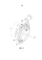
На фиг. 1 показано устройство, предварительно установленное на конце первой трубы, перед зажиманием хомута, вид в перспективе;FIG. 1 is a perspective view of the device pre-installed at the end of the first pipe before clamping the clamp;
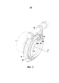
на фиг. 2 - устройство на виде в разрезе по плоскости на фиг. 1, при этом плоскость определена осью трубы и диаметром трубы, проходящим через стопорный элемент;in fig. 2 is a sectional view of the plane of FIG. 1, the plane being defined by the axis of the pipe and the diameter of the pipe passing through the stopper;
на фиг. 3 - отдельно подкладное кольцо на фиг. 1, вид в перспективе;in fig. 3 - a separate backing ring in FIG. 1 is a perspective view;
на фиг. 4 - узел соединения согласно второму варианту осуществления изобретения, вид, аналогичный фиг. 1; иin fig. 4 is a connection unit according to a second embodiment of the invention, a view similar to FIG. one; and
на фиг. 5 - узел соединения согласно третьему варианту осуществления изобретения, вид, аналогичный фиг. 1.in fig. 5 shows a connection unit according to a third embodiment of the invention, a view similar to FIG. one.
Описание начинается с фиг. 1 - 3. На этих фигурах видно, что зажимное устройство содержит хомут 10 в целом того же типа, что описан в документах EP 1451498 и WO 2012013891, и подкладное кольцо 28, которое способствует соединению вместе двух труб 1 и 2. Тем не менее, следует понимать, что изобретение не ограничивается таким типом хомута.The description begins with FIG. 1 to 3. In these figures, it can be seen that the clamping device comprises a
Как упоминалось выше, понятие «внутри» используется для обозначения элементов, которые обращены к оси А двух труб, расположенных торец к торцу, и которые ближе к оси А по сравнению с другими элементами, о которых говорят, что они находятся «снаружи», «наружными» элементами также являются элементы, обращенные от оси А.As mentioned above, the term “inside” is used to denote the elements that face the A-axis of two pipes located end-to-end and which are closer to the A-axis compared to other elements that are said to be “outside”, “ external "elements are also elements facing away from the A axis.
В частности, и как это видно из фиг. 1 и 2, хомут содержит бандаж 12, имеющий внутреннюю периферию, которая ограничивает отступ 14, в который можно вставить опорные поверхности, соответственно опорную поверхность 16, формирующую часть первой трубы 1 и опорную поверхность 18, формирующую часть второй трубы 2. Этот отступ и его опорные поверхности имеют такую форму, что затягивание бандажа хомута ограничивает перемещение концов труб навстречу друг другу. Таким образом, бандаж 12 предпочтительно представляет собой V-образную часть, в то время как опорные поверхности 16 и 18 имеют диаметр, постепенно увеличивающийся в направлении свободных концов труб, и, например, имеют форму усеченного конуса. Бандаж 12 имеет соответствующие концы 12А и 12В, которые стоят по существу радиально, так что формируют несущие лапки. Эти лапки имеют отверстия, через которые проходит стержень 24А болта 24. Головка 24В болта удерживается одной из опорных лапок, в частности, лапкой 12В, в то время как гайка 26 удерживается другой опорной лапкой 12А. Понятно, что вращение гайки в направлении затягивания побуждает опорные лапки перемещаться навстречу друг другу, тем самым уменьшая внутренний диаметр хомута, т.е. позволяет бандажу затягиваться. В частности, удерживающая шайба 26А расположена между опорной лапкой 12А и гайкой 26, при этом эта шайба 26А имеет вырез, который удерживает ее относительно верха V-образного выступа, образованного бандажом 12, чтобы препятствовать ее проворачиванию относительно него при вращении болта 24.In particular, and as shown in FIG. 1 and 2, the clamp comprises a
Зажимное устройство также имеет подкладное кольцо 28, которое прикреплено к хомуту. Это подкладное кольцо имеет участок 30 в виде усеченного конуса, который, как это видно на фиг. 2, подходит для вставления между обращенными друг к другу концами двух труб, когда их зажимают вместе с помощью зажимного устройства. На фиг. 2 видно, что в предварительно установленном состоянии хомута 10 на конце трубы 1, между подкладным кольцом 28, предварительно установленном на внешней периферии 23 первой трубы 1, и внутренней периферией бандажа 12 хомута остается кольцевое пространство Е. На фиг. 1 и 2 также показано, что в предварительно установленном состоянии хомут, по существу, отцентрирован относительно трубы, при этом ось А хомута и подкладного кольца на данных фигурах совпадает с осью первой трубы 1. Таким образом, кольцевое пространство Е позволяет вставить вторую трубу 2 под бандаж 12 хомута и соединить две трубы вместе.The clamping device also has a
В этом отношении видно, что конец трубы 2 является охватывающим концом, и его внутренняя периферия представляет собой раструб. В противоположность этому конец трубы 1 является охватываемым концом, который за пределами опорной поверхности 18 имеет внешнюю периферию 23 с диаметром, который уменьшается в направлении свободного конца. Сформированный таким образом концевой участок может вставляться внутрь раструба 17, сформированного на свободном конце трубы 2, при этом их формы, по существу, взаимодополняющие. Участок 30 подкладного кольца в форме усеченного конуса расположен между раструбом 17 и внешней периферией 23 свободного конца трубы 1. Участок 30 подкладного кольца в форме усеченного конуса имеет деформированные части 32, формирующие уплотнительную прокладку. Таким образом, раструб 17, сформированный на внутренней периферии свободного конца трубы 2, и внешняя периферия концевого участка 23 трубы 1 представляют собой уплотнительные поверхности, которые при затягивании зажимного устройства захватывают участок 30 подкладного кольца в форме усеченного конуса и сжимают уплотнительную прокладку 32, так что соединение труб оказывается герметизированным.In this respect, it can be seen that the end of the
Подкладное кольцо 28 может быть прикреплено к хомуту 10, и предварительная установка узла из хомута 10 и подкладного кольца 28 на первой трубе 1 может выполняться так же, как это описано в документах EP 1451498 и WO 2016034820, с использованием крепежных язычков, имеющихся на подкладном кольце 28.The
Таким образом, подкладное кольцо 28 имеет ряд внутренних язычков 33, которые более четко видны на фиг. 3. Когда подкладное кольцо собрано с хомутом, эти внутренние язычки взаимодействуют с внутренней периферией одного из плеч бандажа 12, в частности, плеча 13А. Эти внутренние язычки предназначены для удержания подкладного кольца на расстоянии от внутренней периферии плеча 13А. Как можно видеть, в частности, из фиг. 1 и 3, крепежные язычки также включают в себя внешние язычки 34, которые имеют достаточную длину, чтобы контактировать со свободным внутренним краем плеча 13А. Внутренние язычки 33 могут немного подниматься радиально в направлении своих свободных концов, так что эти свободные концы более надежно опираются на внутреннюю периферию плеча 13А. В противоположность этому, внешние язычки направлены по существу аксиально, так что проходят под свободный внутренний край плеча 13А. Можно видеть, что свободные концы этих внешних язычков 34 изогнуты, чтобы сформировать соответствующие крюки 34А, которые зацепляются за внешнюю поверхность плеча 13А.Thus, the
Дополнительно, внутренние язычки 33 и внешние язычки 34 могут иметь другие особенности, отличные от подробно описанных в опубликованных патентных документах EP 1451498, WO 2012013891 или FR 3048468. Где это необходимо, внешние язычки 34 могут формировать или включать в себя первые предварительно собранные язычки, которые позволяют предварительно устанавливать зажимное устройство на второй трубе 2.Additionally, the
На фиг. 1 - 3 второе средство предварительной установки содержит язычки 40 предварительной установки, которые расположены на второй стороне подкладного кольца 28, противоположной его первой стороне, и проходят, в частности, в осевом направлении S2 от внешней периферии 28А подкладного кольца. В показанном варианте осуществления, как это лучше видно из фиг. 3, эти язычки предварительной установки аналогичны вторым язычкам предварительной установки, описанным в документе WO 2012013891. Они могут иметь некоторые или все особенности, перечисленные в этом документе, и они могут присутствовать по меньшей мере в описываемых здесь вариантах осуществления, и, в частности, но не исключительно, в показанном на фиг. 7С варианте из упомянутого документа. Второй язычок 40 предварительной установки предназначен для прикрепления подкладного кольца 28 к первой трубе 1. Могут быть использованы другие средства крепления. FIG. 1 to 3, the second presetting means comprises presetting
Кроме того, как упоминалось выше, подкладное кольцо 28 имеет стопорный элемент, предназначенный для взаимодействия с соответствующим позиционирующим элементом первой трубы 1, чтобы предотвращать проворачивание подкладного кольца 28 относительно первой трубы 1. В частности, стопорный элемент содержит стопорный язычок 44, предназначенный для взаимодействия с вырезом 48 в первой трубе 1.In addition, as mentioned above, the
В примерах, показанных на фиг. 1 - 3, стопорный язычок 44 выступает радиально внутрь подкладного кольца 28 и аксиально в направлении свободного конца первой трубы 1, т.е. конца, который должен вводиться в примыкание с концом второй трубы 2. В частности, стопорный язычок 44 продолжает участок 30 в форме усеченного конуса, в этом примере от радиально внутренней стороны подкладного кольца 28. Таким образом, не беря в учет описываемые ниже прорези 46, стопорный язычок 44 выступает, по существу, от участка подкладного кольца 28 с наименьшим диаметром, в частности, от внутренней периферии 28В подкладного кольца 28. Конец стопорного язычка 44, удаленный подкладного кольца 28, т.е. его «дальний» конец, продолжается дальше в направлении внутрь подкладного кольца, чем участок наименьшего диаметра подкладного кольца 28. Кроме того, как видно, в частности, из фиг. 3, стопорный язычок 44 выступает от края подкладного кольца 28, более точно, от края участка 30 в форме усеченного конуса подкладного кольца 28, который удален в осевом направлении от края, от которого выступают крепежные язычки, внутренние язычки 33, внешние язычки 34 и/или вторые язычки 40 предварительной установки. In the examples shown in FIG. 1 to 3, the
Как подробно показано в крупном масштабе на фиг. 2, стопорный язычок 44 проходит радиально через вырез 48, тем самым предотвращая проворачивание подкладного кольца 28 относительно первой трубы 1. С этой целью стопорный язычок 44 может иметь ширину в угловом направлении, несколько меньшую, чем ширина выреза 48 в угловом направлении, например, в диапазоне от 50% до 100% ширины выреза 48 в угловом направлении.As shown on a large scale in FIG. 2, the
В этом варианте стопорный язычок 44 выполнен, по существу, плоским, по меньшей мере, в осевом направлении. В окружном направлении стопорный язычок 44 может иметь кривизну, соответствующую окружной кривизне участка 30 в форме усеченного конуса подкладного кольца 28.In this embodiment, the
Кроме того, гибкость стопорного язычка 44 увеличена посредством прорезей 46 в подкладном кольце с каждой стороны стопорного язычка 44. Как видно, в частности, из фиг. 3, прорези 46 выполнены в продольном направлении и проходят вдоль стопорного язычка 44. Прорези 46 имеют ненулевую составляющую в направлении оси А.In addition, the flexibility of the
Дополнительно, выступающий участок 23 первой трубы 1 проходит от опорной поверхности 16 в виде, по существу, кольцевого удлинения 1А. Кольцевое удлинение 1А предпочтительно имеет диаметр, меньший, чем диаметр остальной части первой трубы 1, так что можно, как это показано на фиг. 2, вводить его в контакт со второй трубой 2 на удлинении 1А, при условии, что вторая труба, за исключением раструба 17, имеет диаметр, по существу, равный диаметру основной части первой трубы 1. Удлинение 1А с равным успехом может иметь другие формы, например, оно может, по существу, иметь форму усеченного конуса, или быть выполнено из множества разрезных удлинений, распределенных в угловом направлении с регулярными интервалами или иным образом.Additionally, the protruding
В этом варианте осуществления удлинение 1А является осевым удлинением, в частности, по существу, цилиндрическим осевым удлинением, т.е. оно является цилиндрическим за исключением, например, выреза 48. Позиционирующий элемент в этом примере представлен вырезом 48, выполненным в удлинении 1А.In this embodiment, the
Более точно, в этом варианте осуществления вырез 48 проходит от края конца первой трубы 1, который выполнен с возможностью введения в контакт со второй трубой 2, и, как и радиальный выступ первой трубы 1, образован в данном примере внешней периферией 23. Таким образом, стопорный язычок 44 и вырез 48 могут начать взаимодействовать, как только зажимное устройство и, в частности, подкладное кольцо 28 надевается на первую трубу 1, и продолжать взаимодействовать до тех пор, пока подкладное кольцо 28 не войдет в контакт с внешней периферией 23 как в незатянутом состоянии, так и в затянутом состоянии зажимного устройства.More specifically, in this embodiment, the
В то же время, вырез 48 может не иметь открытого конца. Другими словами, вместо того, чтобы иметь вырез в прямом смысле слова, позиционирующий элемент может представлять собой отверстие, расположенное на удалении от края конца первой трубы 1. При закреплении зажимного устройства на первой трубе стопорный язычок 44 изгибается, пока не войдет в отверстие, формируя своего рода защелку. Эту операцию легче выполнять, когда стопорный язычок 44 выступает в направлении края конца первой трубы 1.At the same time, the
Попав в отверстие, стопорный язычок 44 возвращается в свое первоначальное положение. Взаимодействие между стопорным язычком 44, представляющим собой стопорный элемент, и отверстием, представляющим собой позиционирующий элемент, в таком случае обеспечивает не только радиальную, но также и осевую блокировку подкладного кольца 28 относительно первой трубы 1. Такая осевая блокировка позволяет зажимному устройству удерживаться на первой трубе 1. Если такое удержание достаточно стабильно, что при необходимости может быть достигнуто использованием нескольких стопорных язычков 44 описанного выше типа, то можно упростить конструкцию или даже исключить вторые язычки 40 предварительной установки, которые предназначены, в частности, для осевой блокировки подкладного кольца 28 относительно первой трубы 1.Once in the hole, the
На фиг. 4 и 5 показан узел соединения в других вариантах осуществления изобретения. На этих фигурах элементы, соответствующие или идентичные элементам первого варианта осуществления, обозначены такими же ссылочными позициями и повторно не описываются.FIG. 4 and 5 show a connection assembly in other embodiments of the invention. In these figures, elements corresponding to or identical to those of the first embodiment are denoted with the same reference numerals and will not be described again.
Второй вариант осуществления, показанный на фиг. 4, идентичен первому варианту осуществления, показанному на фиг. 1, за исключением формы стопорного элемента. В частности, в этом варианте осуществления стопорный элемент представляет собой стопорный язычок 44', изогнутый в осевой части. Как правило, стопорный язычок 44' может иметь форму крюка для зацепления за вырез 48. Кроме того, в этом варианте осуществления подкладное кольцо 28 не имеет прорезей 46.The second embodiment shown in FIG. 4 is identical to the first embodiment shown in FIG. 1, except for the shape of the stopper. Specifically, in this embodiment, the locking element is a locking tab 44 'bent axially. Typically, the locking tab 44 'may be in the form of a hook for engaging with the
Третий вариант осуществления, показанный на фиг. 5, идентичен первому варианту, показанному на фиг. 1, за исключением формы позиционирующего элемента. В частности, в этом варианте осуществления позиционирующий элемент первой трубы 1 представляет собой отступ 48'. Подобно вырезу 48, отступ 48', выполнен в удлинении 1А и проходит от края конца первой трубы 1 до радиального выступа первой трубы 1, который в этом примере сформирован внешней периферией 23. Отступ 48' выступает в радиальном направлении внутрь первой трубы 1. Кроме того, чтобы исключить какой-либо износ первой трубы 1 или стопорного элемента, расстояние до оси А от нижней стенки 48'А отступа 48' меньше, чем расстояние до оси А от дальнего конца 44А стопорного язычка. Отступ 48' может быть выполнен штамповкой.The third embodiment shown in FIG. 5 is identical to the first embodiment shown in FIG. 1, except for the shape of the positioning element. In particular, in this embodiment, the positioning element of the
Во всех показанных вариантах осуществления, если зажимное устройство находится в положении ожидания на конце первой трубы 1, т.е. в предварительно установленном состоянии, с ним можно обращаться как с единым узлом вместе с первой трубой. Для соединения первой трубы 1 со второй трубой 2, вторую трубу подводят к концу первой трубы, вставляя конец второй трубы в вышеупомянутое кольцевое пространство Е, и затем затягивают хомут обычным образом. В частности, зажимное средство хомута содержит вышеупомянутый болт, который при навинчивании гайки на резьбовой хвостовик болта сокращает пространство между лапками 12А и 12В. Естественно, могут быть использованы другие средства затягивания, в частности, чокерный замок или система с защемлением.In all the embodiments shown, if the clamping device is in the waiting position at the end of the
Кроме того, понятно, что стопорный элемент с изогнутым стопорным язычком 44' согласно второму варианту осуществления совместим с отступом 48' согласно третьему варианту осуществления. Могут быть также обеспечены другие формы как для стопорного элемента, так и для позиционирующего элемента, например, выступы, отличающиеся по типу от стопорных язычков 44 и 44'. Стопорный элемент может быть также выполнен с возможностью приема выступа, формирующего позиционирующий элемент первой трубы, в отличие от конфигураций, описанных в вышеприведенных примерах.In addition, it is understood that the curved locking tab stopper 44 'according to the second embodiment is compatible with the offset 48' according to the third embodiment. Other shapes can also be provided for both the locking element and the positioning element, for example protrusions different in type from the locking
В более широком смысле, хотя изобретение описано со ссылкой на конкретные варианты осуществления, могут быть выполнены модификации этих вариантов осуществления, не выходящие за рамки объема изобретения, определяемые формулой изобретения. В частности, в дополнительных вариантах осуществления могут быть объединены индивидуальные особенности согласно различным вариантам осуществления. Соответственно, описание и чертежи следует рассматривать скорее в поясняющем, чем в ограничительном смысле.In a broader sense, although the invention has been described with reference to specific embodiments, modifications may be made to these embodiments without departing from the scope of the invention as defined by the claims. In particular, additional embodiments may combine individual features according to various embodiments. Accordingly, the description and drawings should be considered in an illustrative rather than a restrictive sense.
Claims (12)
Applications Claiming Priority (2)
| Application Number | Priority Date | Filing Date | Title |
|---|---|---|---|
| FR1659571A FR3057047B1 (en) | 2016-10-04 | 2016-10-04 | CONTROLLED ANGULAR POSITION CLAMPING SYSTEM FOR CONNECTING TWO TUBES |
| FR1659571 | 2016-10-04 |
Publications (3)
| Publication Number | Publication Date |
|---|---|
| RU2017134103A RU2017134103A (en) | 2019-04-03 |
| RU2017134103A3 RU2017134103A3 (en) | 2020-10-23 |
| RU2738985C2 true RU2738985C2 (en) | 2020-12-21 |
Family
ID=57583274
Family Applications (1)
| Application Number | Title | Priority Date | Filing Date |
|---|---|---|---|
| RU2017134103A RU2738985C2 (en) | 2016-10-04 | 2017-10-03 | Clamping device for connection of two pipes with controlled angular positioning |
Country Status (9)
| Country | Link |
|---|---|
| US (1) | US10634270B2 (en) |
| EP (1) | EP3306164B1 (en) |
| KR (1) | KR102451029B1 (en) |
| CN (1) | CN107893883B (en) |
| BR (1) | BR102017021143B1 (en) |
| ES (1) | ES2858085T3 (en) |
| FR (1) | FR3057047B1 (en) |
| MX (1) | MX2017012754A (en) |
| RU (1) | RU2738985C2 (en) |
Families Citing this family (12)
| Publication number | Priority date | Publication date | Assignee | Title |
|---|---|---|---|---|
| DE102017121994A1 (en) * | 2017-09-22 | 2019-03-28 | Norma Germany Gmbh | Clamp with sealing element |
| DE102018109581A1 (en) * | 2018-04-20 | 2019-10-24 | Norma Germany Gmbh | clamp |
| FR3080666B1 (en) * | 2018-04-26 | 2020-05-08 | Etablissements Caillau | TIGHTENING SYSTEM WITH FOLDABLE LEGS FOR TUBE CONNECTION |
| JP2020051532A (en) * | 2018-09-27 | 2020-04-02 | いすゞ自動車株式会社 | Temporary holding structure of gasket |
| US20220042629A1 (en) * | 2018-09-28 | 2022-02-10 | Teconnex Ltd | Clamping apparatus and method of use thereof |
| FR3095683B1 (en) * | 2019-05-03 | 2022-12-09 | Caillau | Gasket and clamping device and assembly comprising such a gasket |
| DE102019112884B3 (en) * | 2019-05-16 | 2020-03-26 | Norma Germany Gmbh | Device for pre-positioning a clamp and connection system |
| KR102094381B1 (en) * | 2019-07-18 | 2020-03-27 | 주식회사 뉴아세아조인트 | Coupling assembly for connecting pipes and manufacturing method of the same |
| DE102019126484A1 (en) * | 2019-10-01 | 2021-04-01 | Norma Germany Gmbh | Profile clamp with locking tab |
| FR3108961B1 (en) * | 2020-04-03 | 2022-08-26 | Caillau | Clamping system for connecting pipes, including clamp and seal |
| EP3901507B1 (en) * | 2020-04-03 | 2022-11-02 | Caillau | Tightening system for connecting pipes, comprising a collar and a washer having supporting tabs |
| CN113154157A (en) * | 2021-03-16 | 2021-07-23 | 中国航发哈尔滨东安发动机有限公司 | Quick assembling and disassembling device for end face flange |
Citations (5)
| Publication number | Priority date | Publication date | Assignee | Title |
|---|---|---|---|---|
| UA60392C2 (en) * | 2000-07-07 | 2003-10-15 | Астріум Гмбх | Appliance for split connection of rotary-symmetrical details |
| EP1451498A1 (en) * | 2001-12-05 | 2004-09-01 | Etablissements CAILLAU | Clamping system for the sealed connection of two tubes having support surfaces |
| EP1840439B1 (en) * | 2006-03-30 | 2010-06-16 | Teconnex Ltd. | Clamping device |
| DE202013001224U1 (en) * | 2013-02-07 | 2013-02-15 | Norma Germany Gmbh | Clamp with pre-positioner |
| WO2016034820A1 (en) * | 2014-09-04 | 2016-03-10 | Etablissements Caillau | System for coupling two tubes |
Family Cites Families (17)
| Publication number | Priority date | Publication date | Assignee | Title |
|---|---|---|---|---|
| US2456048A (en) * | 1937-02-01 | 1948-12-14 | Carpenter Container Corp | Sectional container and coupling |
| US2269664A (en) * | 1941-03-14 | 1942-01-13 | United Specialties Co | Seal construction |
| US3822075A (en) * | 1972-08-15 | 1974-07-02 | Diebold Inc | Pneumatic tube coupling |
| US3889984A (en) * | 1974-08-05 | 1975-06-17 | Gen Motors Corp | Integral key-clamp for exhaust pipes |
| US4372017A (en) * | 1980-09-17 | 1983-02-08 | Heckethorn Manufacturing Co. | U-Bolt exhaust system clamp with double saddle |
| DE19534437C2 (en) * | 1995-09-16 | 2000-09-21 | Daimler Chrysler Ag | Clamp for connecting two tubular line parts |
| MXPA06004988A (en) * | 2003-11-07 | 2007-01-19 | Breeze Torca Products Llc | Pipe clamp with integral latch. |
| US7300005B2 (en) * | 2004-10-13 | 2007-11-27 | U.S. Greenfiber, Llc | Single motor blower |
| WO2006086616A2 (en) * | 2005-02-10 | 2006-08-17 | Breeze-Torca Products, Llc | Pipe clamp with gasketed center rib |
| US7770937B2 (en) * | 2007-02-04 | 2010-08-10 | Breeze-Torca Products, Llc | Stepped ball joint pipe clamp and pre-attachment components therefor |
| FR2963404B1 (en) * | 2010-07-27 | 2014-02-07 | Caillau Ets | CLAMPING SYSTEM FOR CONNECTING AND PRE-ASSEMBLING A FIRST AND A SECOND TUBE |
| AU2012227192B2 (en) * | 2010-11-11 | 2013-03-14 | Joinlock Pty Ltd | Improved Connecting Method |
| EP2474721A1 (en) * | 2011-01-11 | 2012-07-11 | Etablissements CAILLAU | Connection device between tubes and clamping system including such connection device |
| DE102011116768A1 (en) * | 2011-10-22 | 2013-04-25 | Norma Germany Gmbh | Clamp with sealing element |
| FR3048468B1 (en) * | 2016-03-07 | 2018-04-06 | Etablissements Caillau | TIGHTENING SYSTEM COMPRISING A NECKLACE AND INDIVIDUAL PRE-ASSEMBLY CLIPS |
| FR3049997B1 (en) * | 2016-04-12 | 2018-05-04 | Etablissements Caillau | CLAMPING DEVICE COMPRISING A CLAMP AND A SLEEVE |
| FR3050232A3 (en) * | 2016-04-15 | 2017-10-20 | Renault Sas | FIXING RING PROTECTION SCREEN |
-
2016
- 2016-10-04 FR FR1659571A patent/FR3057047B1/en active Active
-
2017
- 2017-09-29 KR KR1020170126727A patent/KR102451029B1/en active IP Right Grant
- 2017-09-30 CN CN201710949678.8A patent/CN107893883B/en active Active
- 2017-10-02 BR BR102017021143-6A patent/BR102017021143B1/en not_active IP Right Cessation
- 2017-10-02 US US15/722,162 patent/US10634270B2/en active Active
- 2017-10-03 RU RU2017134103A patent/RU2738985C2/en active
- 2017-10-03 EP EP17194545.4A patent/EP3306164B1/en active Active
- 2017-10-03 ES ES17194545T patent/ES2858085T3/en active Active
- 2017-10-03 MX MX2017012754A patent/MX2017012754A/en unknown
Patent Citations (5)
| Publication number | Priority date | Publication date | Assignee | Title |
|---|---|---|---|---|
| UA60392C2 (en) * | 2000-07-07 | 2003-10-15 | Астріум Гмбх | Appliance for split connection of rotary-symmetrical details |
| EP1451498A1 (en) * | 2001-12-05 | 2004-09-01 | Etablissements CAILLAU | Clamping system for the sealed connection of two tubes having support surfaces |
| EP1840439B1 (en) * | 2006-03-30 | 2010-06-16 | Teconnex Ltd. | Clamping device |
| DE202013001224U1 (en) * | 2013-02-07 | 2013-02-15 | Norma Germany Gmbh | Clamp with pre-positioner |
| WO2016034820A1 (en) * | 2014-09-04 | 2016-03-10 | Etablissements Caillau | System for coupling two tubes |
Also Published As
| Publication number | Publication date |
|---|---|
| FR3057047A1 (en) | 2018-04-06 |
| RU2017134103A (en) | 2019-04-03 |
| BR102017021143B1 (en) | 2022-07-19 |
| ES2858085T3 (en) | 2021-09-29 |
| KR102451029B1 (en) | 2022-10-06 |
| EP3306164B1 (en) | 2020-12-02 |
| BR102017021143A2 (en) | 2018-05-02 |
| EP3306164A1 (en) | 2018-04-11 |
| FR3057047B1 (en) | 2019-05-10 |
| CN107893883A (en) | 2018-04-10 |
| MX2017012754A (en) | 2018-06-13 |
| US20180094755A1 (en) | 2018-04-05 |
| US10634270B2 (en) | 2020-04-28 |
| CN107893883B (en) | 2021-05-07 |
| RU2017134103A3 (en) | 2020-10-23 |
| KR20180037595A (en) | 2018-04-12 |
Similar Documents
| Publication | Publication Date | Title |
|---|---|---|
| RU2738985C2 (en) | Clamping device for connection of two pipes with controlled angular positioning | |
| US6908123B2 (en) | Bayonet quick coupler | |
| US9273706B2 (en) | Hinged clamping collar | |
| US11280435B2 (en) | Profile clamp comprising a sealing element, sealing element for a profile clamp and conduit connection assembly comprising a profile clamp of this type | |
| KR20050044634A (en) | A clamping system for making a leaktight connection between two tubes having bearing surfaces | |
| US11454156B2 (en) | Exhaust clamp and method | |
| US10794518B2 (en) | Profile clamp having sealing element | |
| US9151421B2 (en) | Profiled clamp | |
| KR100393087B1 (en) | Ring clamp for connecting two tubes | |
| US11668418B2 (en) | Connection device | |
| US10161551B2 (en) | Quick-connector | |
| JP2003307210A (en) | Locking nut structure | |
| GB2336638A (en) | Push-fit tube coupling | |
| JP2006242348A (en) | Pipe joint | |
| CN112228434A (en) | Clamping collar with fixing fingers | |
| WO1990008288A1 (en) | Pipe coupling | |
| CN113669530A (en) | Clamping system comprising a collar and a pre-installation clamp | |
| CN111936780B (en) | Clamp apparatus | |
| RU2721488C2 (en) | Device for restriction of nut loosening in gas turbine engine | |
| JPS6220436B2 (en) | ||
| JP2020172954A (en) | Dust-proof cap, attachment structure of the same, and attachment method of the same | |
| RU2780262C2 (en) | Clamping system with bendable lugs for mutual connection of pipes | |
| US12012990B2 (en) | Bushing assembly | |
| JP3778701B2 (en) | Tube connection structure | |
| KR100949611B1 (en) | Insert for an opening of an appliance |
Legal Events
| Date | Code | Title | Description |
|---|---|---|---|
| HE9A | Changing address for correspondence with an applicant |