RU2738762C1 - Implantation needle - Google Patents
Implantation needle Download PDFInfo
- Publication number
- RU2738762C1 RU2738762C1 RU2019131473A RU2019131473A RU2738762C1 RU 2738762 C1 RU2738762 C1 RU 2738762C1 RU 2019131473 A RU2019131473 A RU 2019131473A RU 2019131473 A RU2019131473 A RU 2019131473A RU 2738762 C1 RU2738762 C1 RU 2738762C1
- Authority
- RU
- Russia
- Prior art keywords
- needle
- hollow body
- implant
- cutting edge
- implantation
- Prior art date
Links
Images
Classifications
-
- A—HUMAN NECESSITIES
- A61—MEDICAL OR VETERINARY SCIENCE; HYGIENE
- A61B—DIAGNOSIS; SURGERY; IDENTIFICATION
- A61B17/00—Surgical instruments, devices or methods, e.g. tourniquets
- A61B17/34—Trocars; Puncturing needles
- A61B17/3468—Trocars; Puncturing needles for implanting or removing devices, e.g. prostheses, implants, seeds, wires
-
- A—HUMAN NECESSITIES
- A61—MEDICAL OR VETERINARY SCIENCE; HYGIENE
- A61B—DIAGNOSIS; SURGERY; IDENTIFICATION
- A61B17/00—Surgical instruments, devices or methods, e.g. tourniquets
- A61B17/34—Trocars; Puncturing needles
-
- A—HUMAN NECESSITIES
- A61—MEDICAL OR VETERINARY SCIENCE; HYGIENE
- A61B—DIAGNOSIS; SURGERY; IDENTIFICATION
- A61B5/00—Measuring for diagnostic purposes; Identification of persons
- A61B5/145—Measuring characteristics of blood in vivo, e.g. gas concentration, pH value; Measuring characteristics of body fluids or tissues, e.g. interstitial fluid, cerebral tissue
- A61B5/14532—Measuring characteristics of blood in vivo, e.g. gas concentration, pH value; Measuring characteristics of body fluids or tissues, e.g. interstitial fluid, cerebral tissue for measuring glucose, e.g. by tissue impedance measurement
-
- A—HUMAN NECESSITIES
- A61—MEDICAL OR VETERINARY SCIENCE; HYGIENE
- A61B—DIAGNOSIS; SURGERY; IDENTIFICATION
- A61B5/00—Measuring for diagnostic purposes; Identification of persons
- A61B5/145—Measuring characteristics of blood in vivo, e.g. gas concentration, pH value; Measuring characteristics of body fluids or tissues, e.g. interstitial fluid, cerebral tissue
- A61B5/1486—Measuring characteristics of blood in vivo, e.g. gas concentration, pH value; Measuring characteristics of body fluids or tissues, e.g. interstitial fluid, cerebral tissue using enzyme electrodes, e.g. with immobilised oxidase
- A61B5/14865—Measuring characteristics of blood in vivo, e.g. gas concentration, pH value; Measuring characteristics of body fluids or tissues, e.g. interstitial fluid, cerebral tissue using enzyme electrodes, e.g. with immobilised oxidase invasive, e.g. introduced into the body by a catheter or needle or using implanted sensors
-
- A—HUMAN NECESSITIES
- A61—MEDICAL OR VETERINARY SCIENCE; HYGIENE
- A61M—DEVICES FOR INTRODUCING MEDIA INTO, OR ONTO, THE BODY; DEVICES FOR TRANSDUCING BODY MEDIA OR FOR TAKING MEDIA FROM THE BODY; DEVICES FOR PRODUCING OR ENDING SLEEP OR STUPOR
- A61M37/00—Other apparatus for introducing media into the body; Percutany, i.e. introducing medicines into the body by diffusion through the skin
- A61M37/0069—Devices for implanting pellets, e.g. markers or solid medicaments
-
- A—HUMAN NECESSITIES
- A61—MEDICAL OR VETERINARY SCIENCE; HYGIENE
- A61M—DEVICES FOR INTRODUCING MEDIA INTO, OR ONTO, THE BODY; DEVICES FOR TRANSDUCING BODY MEDIA OR FOR TAKING MEDIA FROM THE BODY; DEVICES FOR PRODUCING OR ENDING SLEEP OR STUPOR
- A61M5/00—Devices for bringing media into the body in a subcutaneous, intra-vascular or intramuscular way; Accessories therefor, e.g. filling or cleaning devices, arm-rests
- A61M5/178—Syringes
- A61M5/31—Details
- A61M5/32—Needles; Details of needles pertaining to their connection with syringe or hub; Accessories for bringing the needle into, or holding the needle on, the body; Devices for protection of needles
- A61M5/3286—Needle tip design, e.g. for improved penetration
-
- A—HUMAN NECESSITIES
- A61—MEDICAL OR VETERINARY SCIENCE; HYGIENE
- A61B—DIAGNOSIS; SURGERY; IDENTIFICATION
- A61B17/00—Surgical instruments, devices or methods, e.g. tourniquets
- A61B2017/00526—Methods of manufacturing
-
- A—HUMAN NECESSITIES
- A61—MEDICAL OR VETERINARY SCIENCE; HYGIENE
- A61B—DIAGNOSIS; SURGERY; IDENTIFICATION
- A61B17/00—Surgical instruments, devices or methods, e.g. tourniquets
- A61B17/32—Surgical cutting instruments
- A61B2017/320044—Blunt dissectors
-
- A—HUMAN NECESSITIES
- A61—MEDICAL OR VETERINARY SCIENCE; HYGIENE
- A61B—DIAGNOSIS; SURGERY; IDENTIFICATION
- A61B17/00—Surgical instruments, devices or methods, e.g. tourniquets
- A61B17/34—Trocars; Puncturing needles
- A61B17/3417—Details of tips or shafts, e.g. grooves, expandable, bendable; Multiple coaxial sliding cannulas, e.g. for dilating
- A61B2017/3454—Details of tips
-
- A—HUMAN NECESSITIES
- A61—MEDICAL OR VETERINARY SCIENCE; HYGIENE
- A61B—DIAGNOSIS; SURGERY; IDENTIFICATION
- A61B2560/00—Constructional details of operational features of apparatus; Accessories for medical measuring apparatus
- A61B2560/06—Accessories for medical measuring apparatus
- A61B2560/063—Devices specially adapted for delivering implantable medical measuring apparatus
Abstract
Description
Область техники, к которой относится изобретениеThe technical field to which the invention relates
Настоящее изобретение относится к имплантационной игле для введения имплантата в тело пациента. Уровень техникиThe present invention relates to an implantation needle for inserting an implant into a patient's body. State of the art
Для введения в кожу имплантатов, например, сенсоров, на глубину приблизительно до 10 мм, известны различные типы имплантационных канюль или игл, например, канюли с замкнутым поперечным сечением и V-образным скосом, щелевые канюли овальной формы с V-образным скосом и разрывные катетеры, т.е. канюльная трубка, разделенная на две части и имеющая V-образный скос, которая затем раскрывается в коже и удаляется отдельными частями.Various types of implantation cannulas or needles are known for inserting implants, such as sensors, into the skin, for example, to a depth of about 10 mm, such as cannulas with closed cross-section and V-bevel, oval-shaped slotted cannulas with V-bevel and bursting catheters , i.e. a cannula tube divided into two parts and having a V-shaped bevel, which is then opened in the skin and removed in separate parts.
С помощью трубчатых игл с замкнутым поперечным сечением и V-образным скосом вводить в кожу плоский сенсор невозможно. Щелевые, т.е. выполненные с продольным разрезом стенки, имплантационные канюли или иглы, имеющие овальную форму, являются более дорогостоящими в изготовлении, чем трубчатые щелевые канюли. Они используются преимущественно для введения имплантатов под углом 90°. Разрывные катетеры также дороже в изготовлении, а вводить и извлекать их обычно дозволяется только врачам или иным квалифицированным медицинским работникам.It is not possible to insert a flat sensor into the skin using tubular needles with a closed cross section and a V-shaped bevel. Slotted, i.e. longitudinally cut walls, implantation cannulas or oval-shaped needles are more expensive to manufacture than tubular slit cannulas. They are used primarily for the insertion of implants at an angle of 90 °. Discontinuous catheters are also more expensive to manufacture, and usually only a physician or other qualified healthcare professional is allowed to insert and remove them.
В документе WO 2015/128263 А1 раскрыта игла для введения имплантата в тело пациента. Эта игла имеет приемную часть, образованную в полом теле иглы с возможностью расположения в ней имплантата, и заостренную концевую часть, образованную путем обработки резанием конца полого тела иглы. Иглу для введения имплантата также можно называть канюлей для введения имплантата. Заостренная концевая часть имеет первую скошенную (наклонную) поверхность, граничащую, т.е. смежную, с наружной боковой, или периферийной, поверхностью полого тела иглы. Первая скошенная поверхность расположена под заданным углом к оси тела иглы. Первую скошенную поверхность также можно называть первичным или базовым срезом. Заостренная концевая часть также имеет пару вторых скошенных поверхностей, граничащих с первой скошенной поверхностью и симметричных относительно острия и оси тела иглы. Пара вторых скошенных поверхностей расположена под углом к оси тела иглы, превышающим заданный угол наклона первой скошенной поверхности относительно оси тела иглы. Пару вторых скошенных поверхностей также можно называть фронтальным срезом. Внешняя кромка пары вторых скошенных поверхностей выполнена в виде режущей кромки, граничащей с острием. Внутренняя и внешняя кромки первой скошенной поверхности выполнены в виде нережущих кромок.Document WO 2015/128263 A1 discloses a needle for inserting an implant into a patient's body. This needle has a receiving part formed in the hollow body of the needle with the possibility of placing an implant therein, and a pointed end part formed by machining the end of the hollow body of the needle. An implant insertion needle can also be called an implant insertion cannula. The tapered end has a first beveled (oblique) surface adjacent, i. E. adjacent, with the outer lateral, or peripheral, surface of the hollow body of the needle. The first beveled surface is located at a predetermined angle to the axis of the needle body. The first beveled surface can also be called the primary or base cut. The tapered end portion also has a pair of second beveled surfaces adjacent to the first beveled surface and symmetrical about the point and axis of the needle body. The pair of second beveled surfaces is located at an angle to the axis of the needle body, which exceeds a predetermined angle of inclination of the first beveled surface relative to the axis of the needle body. A pair of second beveled surfaces can also be called a frontal cut. The outer edge of the pair of the second beveled surfaces is made in the form of a cutting edge adjacent to the tip. The inner and outer edges of the first beveled surface are made in the form of non-cutting edges.
В публикации DE 102011112021 А1 раскрыта игла или канюля с заостренной концевой частью. Канюля с заостренной концевой частью также раскрыта в публикации DE 10224101 А1. При этом предусмотрены первая скошенная поверхность, граничащая с наружной боковой поверхностью полого тела иглы, и пара вторых скошенных поверхностей, граничащих с первой скошенной поверхностью и симметричных относительно острия и оси полого тела иглы.DE 102011112021 A1 discloses a needle or cannula with a pointed end. A cannula with a pointed end is also disclosed in DE 10224101 A1. In this case, a first beveled surface adjoining the outer lateral surface of the hollow body of the needle and a pair of second beveled surfaces adjoining the first beveled surface and symmetrical with respect to the tip and axis of the hollow body of the needle are provided.
Публикация WO 99/53991 А1 относится к троакару с удержанием имплантата, содержащему канюлю для прокалывания кожи животного и обтуратор для ввода имплантата под кожу животного. В этом троакаре с удержанием имплантата дистальный конец канюли выполнен таким образом, чтобы минимизировать травматизацию и разрыв ткани во время введения имплантата. Расположенный внутри канюли упругий элемент в процессе введения имплантата под кожу животного препятствует выпадению вводимого имплантата из канюли. Этот упругий элемент имеет продольную ножку, сложенную зигзагообразно с образованием гармошки. Когда упругий элемент вставлен в канюлю, складчатая форма продольной ножки удерживает имплантат внутри канюли.Publication WO 99/53991 A1 relates to an implant retention trocar comprising a cannula for piercing the skin of an animal and an obturator for inserting the implant under the skin of the animal. In this trocar with implant retention, the distal end of the cannula is designed to minimize trauma and tissue rupture during implant insertion. An elastic element located inside the cannula prevents the inserted implant from falling out of the cannula during the insertion of the implant under the animal's skin. This elastic element has a longitudinal leg folded in a zigzag manner to form an accordion. When the elastic is inserted into the cannula, the folded shape of the longitudinal stem holds the implant inside the cannula.
В публикации US 2010/324579 раскрыт инструмент для подкожной имплантации, имеющий канал с замкнутым поперечным сечением. Рассекающий элемент этого инструмента образует некруглый соосный канал и имеет заостренную режущую кромку, проходящую от нижнего дистального края за пределы отверстия соосного канала, и точку крепления на верхнем дистальном крае. В соосном канале подвижно, с возможностью продольного перемещения, установлен плунжер. В точке крепления с возможностью поворота закреплена крышка, проходящая до нижнего дистального края и в закрытом положении перекрывающая отверстие вблизи режущей кромки.US publication 2010/324579 discloses a subcutaneous implantation instrument having a channel with a closed cross section. The dissecting element of this tool forms a non-circular coaxial canal and has a sharpened cutting edge extending from the lower distal edge beyond the opening of the coaxial canal, and an attachment point at the upper distal edge. A plunger is movable in the coaxial channel with the possibility of longitudinal movement. At the attachment point, a cover is pivotally fixed, extending to the lower distal edge and, in the closed position, overlapping the hole near the cutting edge.
Публикация US 3064651 относится к игле для подкожных инъекций, имеющей осевой канал и скошенной на ее внешнем конце с образованием проникающего в ткань острия, от которого назад проходит наклонно расположенное отверстие канала.Publication No. 3,064,651 relates to a hypodermic needle having an axial canal and beveled at its outer end to form a tissue-penetrating point from which an oblique canal opening extends backward.
Публикация US 3448740 относится к игле для подкожных инъекций с незакупоривающимся просветом, имеющей пяточную часть и концевую часть, оканчивающуюся прокалывающим острием, отличающейся тем, что по меньшей мере один участок ее боковой стенки спирально искривлен от прокалывающего острия до пяточной части, а пяточная часть с возможностью поворота закручена приблизительно на 260…280°, предпочтительно - примерно на 270°, от прокалывающего острия в том же направлении, что и направление спирали указанного участка боковой стенки.Publication US 3448740 relates to a hypodermic needle with a non-clogging lumen having a heel portion and an end portion terminating in a piercing point, characterized in that at least one portion of its side wall is spirally curved from the piercing point to the heel, and the heel is capable of of rotation is twisted by about 260 ... 280 °, preferably by about 270 °, from the piercing point in the same direction as the direction of the spiral of the specified section of the side wall.
В публикации WO 2005/044116 раскрыто режущее устройство для тупоконечной иглы или чрескожно имплантируемого сенсора, вводимого через кожу пациента, причем тупоконечная игла или чрескожно имплантируемый сенсор имеет на дистальном конце периферию, а режущее устройство имеет основу с направляющей, выполненной с возможностью скользящего взаимодействия с иглой или чрескожно имплантируемым сенсором, и режущий элемент для выполнения разреза в коже, имеющий режущую ширину W, которая меньше половины длины периферии тупоконечной иглы или чрескожно имплантируемого сенсора.Publication WO 2005/044116 discloses a cutting device for a blunt-pointed needle or percutaneously implantable sensor inserted through the skin of a patient, wherein the blunt-pointed needle or percutaneously implantable sensor has a periphery at the distal end, and the cutting device has a base with a guide made for sliding interaction with the needle or a percutaneously implantable sensor, and a cutting element for making an incision in the skin, having a cutting width W that is less than half the length of the periphery of a blunt-pointed needle or percutaneously implantable sensor.
Публикация US 4490139 относится к игле для подкожного введения имплантата, выполненной в виде полой трубки, передний конец которой скошен в плоскости, проходящей под острым углом к центральной оси трубки, с образованием эллиптического отверстия и эллиптической внешней кромки, имеющей острую переднюю часть. Передняя концевая часть иглы зашлифована с образованием режущих кромок, пересекающихся под тупым углом и образующих центральную точку. Ширина зашлифованных кромок предпочтительно составляет менее двух третьих диаметра трубки, а примыкающие к зашлифованным кромкам боковые участки эллиптической внешней кромки лишены остроты и притуплены, например, путем обработки абразивными материалами, такой как пескоструйная обработка или галтовка (обработка поверхности в барабане с использованием абразивных материалов). Игла имеет впадины в двух местах, близлежащих к задней кромке отверстия.Publication No. 4,490,139 relates to a hypodermic needle in the form of a hollow tube, the front end of which is beveled in a plane at an acute angle to the central axis of the tube to form an elliptical opening and an elliptical outer edge having a sharp anterior portion. The front end of the needle is ground to form cutting edges that intersect at an obtuse angle and form a center point. The width of the ground edges is preferably less than two-thirds of the tube diameter, and the side portions of the elliptical outer edge adjacent to the ground edges are de-sharp and blunted, for example, by abrasive blasting or tumbling (drum surface treatment using abrasive materials). The needle has two indentations near the trailing edge of the hole.
В документе ЕР 1491225 А1 раскрыта инъекционная игла, содержащая кончик, выполненный путем образования по меньшей мере двух или более шлифованных поверхностей после того, как на кончике трубки иглы сформирована первая шлифованная поверхность, отличающая тем, что кончик иглы находится не на центральной плоскости, где центральная плоскость - это плоскость, вертикально пересекающая первую шлифованную поверхность и включающая центральную ось трубки иглы, в результате чего возможно уменьшение сверлящих болевых ощущений, которые инъекционная игла доставляет пациенту при прокалывании ей кожи.
Документ DE 4235483 А1 относится к полой канюле для инъекций или забора жидкости, имеющей круглое поперечное сечение стержня и наклонную эллиптическую прокалывающую грань с двумя боковыми режущими кромками, сходящимися на кончике канюли. В области режущих кромок канюля является несимметричной. Режущие кромки могут быть неравной длины и/или образовывать неодинаковые углы с осью канюли.DE 4235483 A1 relates to a hollow cannula for injection or fluid intake having a circular shaft cross-section and an oblique elliptical piercing edge with two lateral cutting edges converging at the tip of the cannula. The cannula is asymmetrical in the area of the cutting edges. The cutting edges can be of unequal length and / or form unequal angles with the cannula axis.
Документ US 2005/251190 А1 относится к медицинскому инструменту для проникновения в ткань, который может быть (что необязательно) реализован в форме обтуратора, связанного с троакаром, при этом инструмент содержит удлиненный стержень, имеющий проникающий кончик, установленный на одном его конце. Проникающий кончик имеет основание, прикрепленное к одному концу стержня, и дистальную оконечность, расположенную на некотором расстоянии кнаружи от основания в продольном направлении и сформированную в верхушку, которая может быть определена точкой или иной конфигурацией, спроектированной специально для облегчения проникновения в телесную ткань или ее прокалывания. Верхушка может находиться по существу на одной линии с линейным продолжением центральной продольной оси стержня или, в качестве альтернативы, может отстоять латерально кнаружи или быть смещена от центральной продольной оси стержня. Проникающий кончик также содержит наружную поверхность, проходящую непрерывно между верхушкой и основанием и выполненную с возможностью облегчения прокалывания ткани и расширения отверстия для доступа, образованного в ткани, таким образом, что облегчается отделение ткани и минимизируется разрезание, распарывание или иное повреждение прилегающей телесной ткани вокруг отверстия для доступа. Раскрытие изобретенияUS 2005/251190 A1 relates to a tissue penetration medical instrument, which can optionally be implemented in the form of an obturator associated with a trocar, wherein the instrument comprises an elongated shaft having a penetrating tip mounted on one end thereof. The penetrating tip has a base attached to one end of the rod and a distal tip located some distance outward from the base in the longitudinal direction and formed into an apex, which may be defined by a point or other configuration designed specifically to facilitate penetration into or piercing of bodily tissue ... The apex may be substantially in line with the linear extension of the central longitudinal axis of the shaft, or alternatively it can be laterally outwardly spaced or offset from the central longitudinal axis of the shaft. The penetrating tip also includes an outer surface extending continuously between the apex and the base and configured to facilitate tissue piercing and widen the access opening formed in the tissue, such that tissue separation is facilitated and the cutting, ripping, or other damage to adjacent bodily tissue around the opening is minimized. for access. Disclosure of invention
Задача настоящего изобретения состоит в разработке усовершенствованной имплантационной иглы для введения в тело пациента имплантата, например, сенсора, такого как сенсор-анализатор, предпочтительно электрохимического сенсора, такого как сенсор, регистрирующий уровень глюкозы. Такая игла должна обеспечивать возможность неразрушающего введения имплантата.An object of the present invention is to provide an improved implant needle for inserting an implant into a patient's body, for example a sensor, such as a sensor-analyzer, preferably an electrochemical sensor, such as a glucose sensor. Such a needle should be capable of non-destructive insertion of the implant.
Имплантационная игла может быть выполнена с возможностью чрескожного введения имплантата, при котором часть имплантата помещается под кожу, а другую часть имплантата находится над поверхностью кожи. В качестве альтернативы имплантационная игла может быть выполнена для проведения полной имплантации, когда весь имплантат помещают под кожу. Кроме того, имплантационная игла должна поддерживать традиционную имплантацию в тело пациента.The implantation needle can be configured for percutaneous implantation, in which part of the implant is placed under the skin and the other part of the implant is located above the skin surface. Alternatively, an implantation needle can be configured to perform a complete implantation where the entire implant is placed under the skin. In addition, the implantation needle must support traditional implantation into the patient's body.
Согласно настоящему изобретению предложена имплантационная игла для введения имплантата в тело пациента, охарактеризованная в пункте 1 формулы. Предпочтительные варианты выполнения изобретения приведены в зависимых пунктах формулы изобретения.According to the present invention, there is provided an implantation needle for inserting an implant into a patient's body, as defined in
Одним объектом изобретения является имплантационная игла для введения имплантата в тело пациента. Имплантационная игла содержит приемный участок, образованный в полом теле иглы с возможностью расположения в нем имплантата, и заостренную концевую часть. Заостренная концевая часть имеет первую скошенную поверхность, граничащую с первой наружной периферической поверхностью полого тела иглы, причем первая скошенная поверхность выполнена в виде первой нережущей кромки, вторую скошенную поверхность, граничащую со второй наружной периферической поверхностью полого тела иглы, причем вторая скошенная поверхность выполнена в виде второй нережущей кромки, и пару заточенных поверхностей, симметричных относительно острия и продольной оси полого тела иглы, причем обе заточенные поверхности снабжены режущей кромкой. Первая скошенная поверхность включает первый бок, а вторая скошенная поверхность включает второй бок. Первый бок выполнен, начинающимся на первом расстоянии от острия, а второй бок выполнен, начинающимся на втором расстоянии от острия, отличающемся от первого.One aspect of the invention is an implantation needle for inserting an implant into a patient's body. The implantation needle contains a receiving section formed in the hollow body of the needle with the possibility of placing an implant in it, and a pointed end part. The sharpened end part has a first beveled surface adjoining the first outer peripheral surface of the hollow body of the needle, and the first beveled surface is made in the form of the first non-cutting edge, the second beveled surface adjacent to the second outer peripheral surface of the hollow body of the needle, and the second beveled surface is made in the form the second non-cutting edge, and a pair of sharpened surfaces, symmetrical with respect to the tip and the longitudinal axis of the hollow body of the needle, and both sharpened surfaces are provided with a cutting edge. The first beveled surface includes a first flank, and the second beveled surface includes a second flank. The first side is made starting at the first distance from the tip, and the second side is made starting at the second distance from the tip, different from the first.
В контексте настоящего описания под полым телом имплантационной иглы понимается полое тело, снабженное отверстием в боковой стенке полого тела иглы, проходящим в продольном направлении имплантационной иглы. Таким образом, полое тело иглы также можно назвать открытым полым телом иглы. Иными словами, полое тело иглы - это не канюля, имеющая форму замкнутой трубки.In the context of the present description, a hollow body of an implantation needle is understood as a hollow body provided with an opening in the side wall of the hollow body of the needle extending in the longitudinal direction of the implantation needle. Thus, the hollow body of the needle can also be called the open hollow body of the needle. In other words, the hollow body of the needle is not a cannula in the form of a closed tube.
Отверстие в боковой стенке полого тела иглы может проходить вдоль всей его длины. В качестве альтернативы, отверстие в боковой стенке полого тела иглы может проходить только вдоль части его длины. В случае, если отверстие проходит только вдоль части длины полого тела иглы, оно проходит до дистального конца полого тела иглы, раскрываясь по направлению к заостренной концевой части.The hole in the side wall of the hollow body of the needle can extend along its entire length. Alternatively, the hole in the side wall of the hollow body of the needle may only extend along a portion of its length. In case the hole extends only along a part of the length of the hollow body of the needle, it extends to the distal end of the hollow body of the needle, opening towards the pointed end portion.
Отверстие в боковой стенке полого тела иглы может быть образовано симметричным по отношению к продольной оси полого тела иглы. Отверстие в боковой стенке полого тела иглы может быть выполнено в виде щелевого отверстия, что позволяет получить щелевое полое тело иглы.The hole in the side wall of the hollow body of the needle can be formed symmetrical with respect to the longitudinal axis of the hollow body of the needle. The hole in the side wall of the hollow body of the needle can be made in the form of a slotted hole, which makes it possible to obtain a slotted hollow body of the needle.
Наличие отверстия в боковой стенке полого тела иглы обеспечивает возможность расположения контактного конца имплантата в положении вне пределов приемного участка полого тела иглы.The presence of a hole in the side wall of the hollow body of the needle makes it possible to position the contact end of the implant in a position outside the receiving area of the hollow body of the needle.
Наличие отверстия в боковой стенке полого тела иглы обеспечивает возможность извлечения имплантационной иглы из тела пациента после введения имплантата, без изменения положения имплантата.The presence of a hole in the side wall of the hollow body of the needle makes it possible to remove the implantation needle from the patient's body after insertion of the implant, without changing the position of the implant.
Внутренние кромки, образованные на протяжении отверстия в боковой стенке полого тела иглы, могут быть выполнены нережущими.The inner edges formed along the hole in the side wall of the hollow body of the needle can be made non-cutting.
Заостренная концевая часть, например, может быть образована путем обработки резанием концевой части полого тела иглы.The pointed end portion, for example, can be formed by machining the end portion of the hollow body of the needle.
В соответствии с изобретением обе заточенные поверхности выполнены в виде нескошенной поверхности в плоской концевой части, граничащей с острием. Плоская концевая часть может быть симметричной относительно продольной оси полого тела иглы.In accordance with the invention, both sharpened surfaces are formed as a non-beveled surface in a flat end portion adjacent to the point. The flat end can be symmetrical about the longitudinal axis of the hollow body of the needle.
По меньшей мере один из первого и второго боков может граничить с одной из заточенных поверхностей.At least one of the first and second sides may abut one of the sharpened surfaces.
По меньшей мере один из первого и второго боков может граничить с режущей кромкой одной из заточенных поверхностей.At least one of the first and second sides may abut the cutting edge of one of the sharpened surfaces.
По меньшей мере другой из первого и второго боков может граничить с незаточенной поверхностью, которая, в свою очередь, граничит с заточенной поверхностью, имеющей режущую кромку. У незаточенных поверхностей какая-либо режущая кромка отсутствует, а, следовательно, они снабжены нережущими кромками. Незаточенная поверхность может быть выполнена в плоской концевой части.At least the other of the first and second flanks may abut an unsharpened surface, which in turn abuts a sharpened surface having a cutting edge. Unsharpened surfaces do not have any cutting edge and are therefore provided with non-cutting edges. The unsharpened surface can be made in the flat end part.
У по меньшей мере одного из первого и второго боков соответствующая ему первая или вторая наружная периферическая поверхность может быть изогнута наружу.At at least one of the first and second sides, the corresponding first or second outer peripheral surface may be curved outwardly.
Для по меньшей мере одной из заточенных поверхностей режущая кромка может быть выполнена на внешней кромке. Внутренняя кромка может быть снабжена нережущей кромкой. В альтернативном варианте выполнения внутренняя кромка может быть снабжена режущей кромкой, в то время как внешняя кромка снабжена нережущей кромкой. В еще одном альтернативном варианте выполнения режущей кромкой могут быть снабжены как внешняя кромка, так и внутренняя кромка заточенных поверхностей.For at least one of the sharpened surfaces, the cutting edge can be formed on the outer edge. The inner edge can be provided with a non-cutting edge. Alternatively, the inner edge can be provided with a cutting edge while the outer edge is provided with a non-cutting edge. In yet another alternative embodiment, both the outer edge and the inner edge of the sharpened surfaces can be provided with a cutting edge.
Как первый, так и второй бока могут быть выполнены в виде сформированного вырубкой и гибкой компонента.Both the first and second flanks can be formed as a die-formed and flexible component.
По меньшей мере один из первого и второго боков может быть выполнен по соседству с плоским участком, дистальным по отношению к острию.At least one of the first and second sides can be formed adjacent to a flat portion distal to the tip.
Плоский участок может граничить с плоской концевой частью.The flat section may adjoin the flat end.
Приемный участок может содержать выемку, проходящую через полое тело иглы. Выемка может быть образована симметричной по отношению к продольной оси полого тела иглы.The receiving area may include a recess extending through the hollow body of the needle. The recess can be formed symmetrical with respect to the longitudinal axis of the hollow body of the needle.
Полое тело может иметь круглое или овальное поперечное сечение.The hollow body can have a circular or oval cross-section.
Заостренная концевая часть может быть снабжена плоским участком.The tapered end can be provided with a flat portion.
В контексте настоящего описания подразумевается, что режущая кромка создает прорез в коже, а нережущая кромка обычно кожу не режет. Например, режущая кромка может быть получена утонением слоя материала по направлению к кромке.In the context of the present disclosure, it is understood that the cutting edge creates an incision in the leather, and the non-cutting edge does not typically cut the leather. For example, a cutting edge can be obtained by thinning a layer of material towards the edge.
Нережущие кромки можно получать, например, шлифованием, лазерной или гидроабразивной резкой. Нережущие кромки можно получить путем закругления кромок после обработки материала резанием.Non-cutting edges can be obtained, for example, by grinding, laser cutting or waterjet cutting. Non-cutting edges can be obtained by rounding the edges after cutting the material.
Одна или несколько нережущих кромок может (могут) быть выполнена(ы) закругленной(-ыми). Для закругления кромки может использоваться окончательная обработка (доводка) поверхности с помощью струйно-абразивной обработки или полирования. Струйно-абразивная обработка может проводиться, например, с применением стеклянных шариков, частиц корунда и песка. Широко известным методом является полирование, например, электрополирование в текучей среде.One or more non-cutting edges can (can) be made (are) rounded (s). Finishing (lapping) of the surface by blasting or polishing can be used to round the edge. Blasting can be carried out, for example, using glass beads, corundum particles and sand. A well known technique is polishing, such as electropolishing in a fluid.
В процессе производства иглы закругление может быть обеспечено шлифованием и/или электрополированием. В дополнение к этим методам или в качестве альтернативы им может использоваться струйно-абразивная обработка. В качестве альтернативы нережущие кромки могут быть получены только посредством струйно-абразивной обработки.During the needle manufacturing process, rounding can be achieved by grinding and / or electropolishing. In addition to or as an alternative to these methods, abrasive blasting can be used. Alternatively, non-cutting edges can only be obtained by abrasive blasting.
Полое тело иглы на его приемном участке может иметь поперечное сечение U- или V-образной формы. По отношению к заостренной концевой части может быть предусмотрен скос. Отверстие в боковой стенке полого тела иглы может граничить с этим скосом, предусмотренным по отношению к заостренной концевой части.The hollow body of the needle at its receiving area can have a cross-section of a U- or V-shape. A bevel may be provided with respect to the pointed end portion. An opening in the side wall of the hollow body of the needle may adjoin this bevel provided with respect to the pointed end portion.
Ниже приведено описание способа изготовления имплантационной иглы. При возможном осуществлении способа проделывают ряд технологических операций. Сначала вырубают плоскую металлическую полосу или лист для создания заготовки в виде плоского листа требуемой формы, подходящего для последующей гибки листа для того, чтобы он принял форму канюли или имплантационной иглы. Затем, на втором шаге лист могут подвергнуть зачеканиванию "затупленных" нережущих кромок на части листа. Затем, на следующем шаге, могут согнуть канюлю, и кончик канюли могут зачеканить и вырубить для создания предлагаемой в изобретении канюли. В качестве альтернативы для создания острого кончика канюли можно использовать технологии травления.The following is a description of a method for manufacturing an implantation needle. With a possible implementation of the method, a number of technological operations are performed. First, a flat metal strip or sheet is punched out to create a flat sheet blank of the desired shape suitable for subsequent bending of the sheet to form a cannula or implantation needle. Then, in a second step, the sheet may be stamped with "blunt" non-cutting edges on a portion of the sheet. Then, in the next step, the cannula can be bent and the tip of the cannula can be stamped and punched out to create a cannula of the invention. Alternatively, etching techniques can be used to create a sharp cannula tip.
Способ изготовления имплантационной иглы может включать получение по меньшей мере первого и второго боков по меньшей мере по одной из двух технологий, первая из которых - это вырубочно-гибочная технология, а вторая представляет собой комбинацию технологического процесса травления с процессом гибки. Вырубочно-гибочная технология, являющаяся комбинацией вырубки и гибки материала, используемого для изготовления имплантационной иглы, сочетаются для получения по меньшей мере одного из боков. Такую вырубочно-гибочную технологию также можно использовать для изготовления полого тела иглы.A method for manufacturing an implantation needle may include obtaining at least the first and second sides by at least one of two technologies, the first of which is a punching and bending technology, and the second is a combination of an etching process with a bending process. Punching and bending technology, which is a combination of punching and bending of the material used to make the implantation needle, are combined to produce at least one of the sides. This die-bending technique can also be used to make a hollow needle body.
Способ может включать: получение полого тела иглы, имеющего просвет, окруженный периферийной стенкой, и приемный участок, образованный в полом теле иглы с возможностью расположения в нем имплантата. Заостренная концевая часть произведена так, что она имеет первую скошенную поверхность, граничащую с первой наружной периферической поверхностью полого тела иглы, причем первая скошенная поверхность выполнена в виде первой нережущей кромки, вторую скошенную поверхность, граничащую со второй наружной периферической поверхностью полого тела иглы, причем вторая скошенная поверхность выполнена в виде второй нережущей кромки, и пару заточенных поверхностей, симметричных относительно острия и продольной оси полого тела иглы, причем обе заточенные поверхности снабжены режущей кромкой. Первая скошенная поверхность включает первый бок, а вторая скошенная поверхность включает второй бок. Первый бок выполнен, начинающимся на первом расстоянии от острия, а второй бок выполнен, начинающимся на втором расстоянии от острия, отличающемся от первого.The method may include: providing a hollow needle body having a lumen surrounded by a peripheral wall and a receiving portion formed in the hollow needle body with the possibility of placing an implant therein. The sharpened end part is made so that it has a first beveled surface adjoining the first outer peripheral surface of the hollow needle body, the first beveled surface is made in the form of a first non-cutting edge, the second beveled surface adjacent to the second outer peripheral surface of the hollow needle body, and the second the beveled surface is made in the form of a second non-cutting edge, and a pair of sharpened surfaces, symmetric with respect to the tip and the longitudinal axis of the hollow body of the needle, and both sharpened surfaces are provided with a cutting edge. The first beveled surface includes a first flank, and the second beveled surface includes a second flank. The first side is made starting at the first distance from the tip, and the second side is made starting at the second distance from the tip, different from the first.
Краткое описание чертежейBrief Description of Drawings
Ниже приведено подробное описание изобретения на примере вариантов его выполнения, сделанное со ссылками на прилагаемые чертежи, на которых показано:Below is a detailed description of the invention by way of example of its embodiments, made with reference to the accompanying drawings, which show:
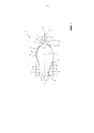
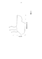
на фиг. 1 вид сверху концевого фрагмента имплантационной иглы, имеющей полое тело иглы или канюли с заостренной концевой частью;in fig. 1 is a top view of an end portion of an implantation needle having a hollow needle body or cannula with a pointed end portion;
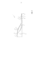
на фиг. 2 - вид сбоку концевого фрагмента, показанного на фиг. 1;in fig. 2 is a side view of the end portion shown in FIG. one;
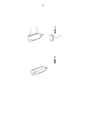
на фиг. 3 - известная из уровня техники имплантационная игла с симметричными боками;in fig. 3 - an implantation needle known from the prior art with symmetrical sides;
на фиг. 4 имплантационная игла, у которой первый бок выполнен на первом расстоянии от острия, а второй бок выполнен на втором расстоянии от острия, отличающемся от первого;in fig. 4 an implantation needle, in which the first side is made at a first distance from the point, and the second side is made at a second distance from the point, different from the first;
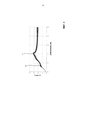
на фиг. 5 графическое представление силы проникновения имплантационной иглы, показанной на фиг. 3;in fig. 5 is a graphical representation of the penetration force of the implantation needle shown in FIG. 3;
на фиг. 6 - графическое представление силы проникновения имплантационной иглы, показанной на фиг. 4; иin fig. 6 is a graphical representation of the penetration force of the implantation needle shown in FIG. 4; and
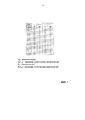
на фиг. 7 экспериментальные результаты для имплантационной иглы, показанной на фиг. 4.in fig. 7 experimental results for the implantation needle shown in FIG. 4.
Осуществление изобретенияImplementation of the invention
На фиг. 1 и 2 показана предлагаемая в изобретении имплантационная игла 1, имеющая полое тело 2 иглы или канюли. Полое тело 2 иглы снабжено заостренной концевой частью 3 на конце 4.FIG. 1 and 2 show an
Полое тело 2 иглы содержит приемный участок 5, снабженный отверстием, проходящим в продольном направлении имплантационной иглы, которое в показанном варианте выполнения сформировано в виде щелевого отверстия 6. Щелевое отверстие 6 может проходить вдоль всей длины полого тела 2 иглы (не показанного на фиг. 1 и 2 во всю свою длину) или вдоль отрезка полого тела 2 иглы.The
Приемный участок 5 выполнен с возможностью вмещения имплантируемого элемента (на чертежах не показан), например, сенсора (датчика), подлежащего введению через кожу в тело человека или животного имплантационной иглой 1. Для имплантации имплантат помещают в приемный участок 5. После прокалывания через кожу в тело имплантационную иглу 1 извлекают, а имплантат остается в теле. Во время извлечения имплантационной иглы 1 имплантируемый элемент выскальзывает из приемного участка 5.The receiving
Внутренние кромки 7а, 7b, образованные на протяжении щелевого отверстия 6 или приемного участка 5, выполнены нережущими. Это также способствует предотвращению повреждения имплантируемого элемента, когда он покидает приемный участок 5 во время имплантации. Внешние кромки 8а, 8b также выполнены нережущими.The
В заостренной концевой части 3 предусмотрена пара заточенных поверхностей 9а, 9b. Пара заточенных поверхностей 9а, 9b выполнена граничащей с острием 10. Внешние кромки 11а, 11b заточенных поверхностей 9а, 9b выполнены режущими. Внутренние кромки 12а, 12b заточенных поверхностей 9а, 9b в показанном варианте выполнения выполнены нережущими.A pair of sharpened
Заточенные поверхности 9а, 9b являются симметричными по отношению к острию 10 и продольной оси 13 полого тела 2 иглы.The sharpened
Первая скошенная поверхность 14а выполнена на первом боку (боковой стенке) 14b, гранича с первой наружной периферической поверхностью 15 полого тела 2 иглы. Вторая скошенная поверхность 16а выполнена на втором боку 16b, гранича со второй наружной периферической поверхностью 17 полого тела 2 иглы. Первый бок 14b выполнен на первом расстоянии от острия 10. Второй бок 16b выполнен, начинающимся на втором расстоянии от острия 10, при этом первое расстояние отличается от второго расстояния, в результате чего получается конструкция, несимметричная с точки зрения местоположения первого и второго боков 14b, 16b по отношению к острию 10.The first
Первый бок 14b выполнен по соседству с плоским участком 18, который, в свою очередь, граничит с плоской концевой частью 19. В рассматриваемом варианте выполнения первый бок 14b выполнен в центральной части плоского участка 18, в то время как второй бок 16b, также находящийся по соседству с плоским участком 18, выполнен в области 20 дистального конца плоского участка 18, причем область 20 дистального конца находится на большей дистанции от острия 10. Второй бок 16b может быть расположен в переходной зоне, в которой неплоский участок 21 полого тела 2 иглы граничит с плоским участком 18.The
По отношению к первому и второму бокам 14b, 16b первая и вторая наружные периферические поверхности 15, 17 изогнуты наружу. Степень изогнутости наружу первой и второй наружных периферических поверхностей 15, 17 может быть одинаковой. В альтернативном варианте первая и вторая наружные периферические поверхности 15, 17 могут быть изогнуты наружу в разной степени.With respect to the first and
Если имплантационная игла 1 используется для создания разреза кожи, то кожа прорезается заточенными поверхностями 9а, 9b. Далее, из-за того, что кромки нережущие, кожа приподнимается первым и вторым боками 14b, 16b. Сначала кожа поднимается первым боком 14b на одной стороне имплантационной иглы 1. Позднее, когда заостренную концевую часть 3 вводят далее внутрь кожи, кожа поднимается вторым боком 16b. Следовательно, подъем кожи происходит постепенно шаг за шагом, что способствует неразрушающей имплантации имплантата, подлежащего введению в тело пациента имплантационной иглой 1.If the
В процессе изготовления имплантационной иглы 1 по меньшей мере первый и второй бока 14b, 16b могут быть получены по меньшей мере по одной из двух технологий, первая из которых это вырубочно-гибочная технология, а вторая представляет собой комбинацию технологического процесса травления с процессом гибки. Вырубочно-гибочная технология, являющаяся комбинацией вырубки и гибки материала, используемого для изготовления имплантационной иглы 1, сочетаются для получения по меньшей мере одного из боков 14b, 16b. Такую вырубочно-гибочную технологию также можно использовать для изготовления полого тела 2 иглы.In the process of manufacturing the
Способ производства может включать вырубку плоской металлической полосы или листа для создания заготовки в виде плоского листа требуемой формы, подходящего для последующей гибки листа для того, чтобы он принял форму канюли. Затем, в ходе следующего шага лист могут подвергнуть зачеканиванию "затупленных" нережущих кромок на части листа. Затем, на другом шаге, могут согнуть канюлю, и концевую часть канюли могут зачеканить и вырубить для создания канюли. В качестве альтернативы для создания острого кончика канюли можно использовать технологии травления.The manufacturing method may include punching out a flat metal strip or sheet to create a flat sheet blank of the desired shape suitable for subsequent bending of the sheet into a cannula shape. Then, in the next step, the sheet may be stamped with "blunt" non-cutting edges on a portion of the sheet. Then, in another step, the cannula can be bent, and the end of the cannula can be stamped and punched out to create the cannula. Alternatively, etching techniques can be used to create a sharp cannula tip.
Предлагаемая в альтернативных вариантах выполнения имплантационная игла обеспечивает неожиданное преимущество, заключающееся в том, что изготовление имплантационной иглы, начинающееся с плоского металлического листа, позволяет удешевить и ускорить производство иглы по сравнению с дорогостоящими процессами изготовления, используемыми для создания известных из уровня техники игл, изготовленных обработкой резанием и заточкой замкнутых металлических цилиндров.An implantation needle of alternative embodiments provides the unexpected advantage that manufacturing an implant needle starting from a flat metal sheet allows for a cheaper and faster manufacturing of the needle compared to the expensive manufacturing processes used to create prior art needles made by machining cutting and sharpening closed metal cylinders.
Были испытаны канюли и имплантационные иглы различных типов. На фиг. 3 показана имплантационная игла, имеющая симметричные бока и по существу круглое поперечное сечение, как в известных в данной области конструкциях. На фиг. 4 показана имплантационная игла 1, изображенная на фиг. 1 и 2.Cannulas and implantation needles of various types have been tested. FIG. 3 shows an implantation needle having symmetrical sides and a substantially circular cross-section, as is known in the art. FIG. 4 shows the
На каждой из фиг. 5 и 6 показано графическое представление силы проникновения, измеренной, соответственно, для имплантационной иглы, показанной на фиг. 3, и имплантационной иглы, показанной на фиг. 4.In each of FIG. 5 and 6 are graphical representations of the penetration force measured, respectively, for the implantation needle shown in FIG. 3 and the implantation needle shown in FIG. 4.
Имплантационная игла, относящаяся к иллюстрациям на фиг. 1, 2 и 4, выполнена с возможностью поддержания пониженных сил проникновения во время введения в кожу по сравнению с имплантационной иглой с симметричными кромками, такой как показанная на фиг. 3. Этот удивительный результат, в свою очередь, уменьшает болевые ощущения пациента при использовании таких игл.The implantation needle referring to the illustrations in FIG. 1, 2 and 4 is configured to maintain reduced penetration forces during insertion into the skin as compared to an implantation needle with symmetrical edges such as shown in FIG. 3. This surprising result, in turn, reduces patient pain when using these needles.
Были проведены испытания имплантационных игл, показанных на фиг. 3 и 4, путем моделирования введения в кожу человека в ходе процедуры по методике согласно германскому стандарту DIN 13097-4 следующим образом: полиуретановую пленку в соответствии с DIN 13097-4 (тест-полоски из полиуретановой пленки, выпускаемые компанией "melab Medizintechnik und Labor GmbH" (Леонберг, Германия)) зафиксировали в испытательном положении и использовали на месте в качестве системы моделирования кожи. В каждом испытании отдельный экземпляр полиуретановой пленки прокалывали исследуемой имплантационной иглой.The implantation needles shown in FIG. 3 and 4, by simulating the injection into human skin during the procedure according to the procedure according to the German standard DIN 13097-4 as follows: polyurethane film according to DIN 13097-4 (polyurethane film test strips manufactured by melab Medizintechnik und Labor GmbH (Leonberg, Germany)) was fixed in a test position and used in situ as a skin modeling system. In each test, a separate specimen of the polyurethane film was pierced with the test implant needle.
Для каждой из двух имплантационных игл были определены нижеследующие параметры, а также их соответствующие средние значения и стандартные отклонения:For each of the two implantation needles, the following parameters were determined, along with their respective mean values and standard deviations:
F0 - сила [Н], прикладываемая кончиком иглы, проникающим в полиуретановую пленку;F0 - force [N], applied by the tip of the needle, penetrating into the polyurethane film;
Fmax максимальная сила [Н], прикладываемая при вхождении наиболее широкой части кончика иглы (представленной соответствующим(и) боком(-ами) кончика) в полиуретановую пленку;Fmax is the maximum force [N] applied when the widest part of the needle tip (represented by the corresponding side (s) of the tip) enters the polyurethane film;
Fmin минимальная сила [Н], прикладываемая при извлечении иглы из полиуретановой пленки.Fmin is the minimum force [N] applied when removing the needle from the polyurethane film.
Эксперимент был проведен для испытаний на проникновение по методике, изложенной в стандарте DSN 13097-4. Процедура испытаний включает последовательные шаги: зажимание имплантационной иглы, запуск стандартной программы из системы программного обеспечения, перемещение полиуретановой пленки и открепление имплантационной иглы от обжимного инструмента.The experiment was carried out for penetration testing according to the method described in the standard DSN 13097-4. The test procedure includes sequential steps: clamping the implantation needle, launching a standard program from the software system, moving the polyurethane film and detaching the implantation needle from the crimping tool.
На фиг. 7 показаны экспериментальные результаты для имплантационной иглы, показанной на фиг. 4, названной "С2.1-х", где х=1…20. Усредненное значение максимальных сил Fmax проникновения, определенных для испытанных имплантационных игл, равно 2,63 Н.FIG. 7 shows experimental results for the implantation needle shown in FIG. 4, named "C2.1-x", where x = 1 ... 20. The average value of the maximum penetration forces Fmax determined for the tested implantation needles is 2.63 N.
Имплантационная игла, показанная на фиг. 4, демонстрирует меньшую максимальную силу Fmax проникновения, а также наименьшее стандартное отклонение. Имплантационная игла, показанная на фиг. 4, ассоциируется с превосходными эксплуатационными характеристиками в модельных условиях с кожесимулятором (имитатором кожи), что служит поддержкой мнения, что сопоставимые эксплуатационные характеристики могут быть продемонстрированы в "физиологической" обстановке (in vivo) введения в кожу пользователя.The implantation needle shown in FIG. 4 demonstrates the lower maximum penetration force Fmax, as well as the smallest standard deviation. The implantation needle shown in FIG. 4 is associated with superior performance under simulated conditions with a skin simulator, which supports the view that comparable performance can be demonstrated in a "physiological" (in vivo) setting of insertion into a user's skin.
Обращает на себя внимание тот факт, что имплантационная игла, показанная на фиг. 3, имеющая симметричные бока, показала низкие эксплуатационные характеристики (см. ниже). Конструкция поперечного сечения иглы в области кончика обусловила увеличенную силу проникновения, что следует ассоциировать с повышенными болевыми ощущениями для пациента по сравнению с имплантационной иглой, показанной на фиг. 4.Noteworthy is the fact that the implantation needle shown in FIG. 3, with symmetrical sides, showed low performance (see below). The cross-sectional design of the needle in the tip region resulted in an increased penetration force, which should be associated with increased pain for the patient compared to the implantation needle shown in FIG. 4.
Как показано на фиг. 5, при проникновении в кожесимулятор имплантационной иглы, показанной на фиг. 3, оба симметричных бока пронзали пленку одновременно и расширение кожесимулятора происходило одношагово. Максимальная сила была приложена в момент вхождения обоих боков в кожесимулятор. На фиг. 5 имеются два локальных максимума: 50 вход кончика иглы в кожу, а 51 - вход боков иглы.As shown in FIG. 5, when the implant needle of FIG. 3, both symmetrical sides pierced the film simultaneously and the expansion of the skin simulator occurred in one step. The maximum force was applied when both sides entered the simulator. FIG. 5, there are two local maxima: 50 is the entry of the needle tip into the skin, and 51 is the entry of the sides of the needle.
В табл. 1 приведены экспериментальные результаты для имплантационной иглы, показанной на фиг. 3.Table 1 shows the experimental results for the implantation needle shown in FIG. 3.

Как показано на фиг. 6, при проникновении в кожесимулятор имплантационной иглы, показанной на фиг. 4, бока пронзали пленку в разные моменты времени, т.е. бок, начинающийся на более коротком расстоянии от острия, пронзал пленку раньше, чем бок, начинающийся на более длинном расстоянии от острия 10. Максимальная сила была приложена в момент вхождения обоих боков в кожесимулятор. На фиг. 6 есть три локальных максимума: 60 - вход кончика иглы в кожу, 61 - вход первых боков иглы, и 62 - вход второго бока иглы. В то время как вход кончика иглы (момент времени, соответствующий подписи 60 на графике) - это довольно малый локальный максимум, другие максимумы на показанном на фиг. 6 графике являются хорошо выраженными.As shown in FIG. 6, when the implant needle of FIG. 4, the sides pierced the film at different times, i.e. the side starting at a shorter distance from the tip pierced the film earlier than the side starting at a longer distance from the
В табл. 2 приведены экспериментальные результаты для имплантационной иглы, показанной на фиг. 4.Table 2 shows the experimental results for the implantation needle shown in FIG. 4.

Второй максимум 61 на приведенном на фиг. 6 графике, выражающем корреляцию между путем деформации и силой проникновения, стал следствием того факта, что первый бок поднял полиуретановую пленку и еще больше расширил место прокола без разрезания. Затем наблюдалось небольшое падение силы, так как преобладало только трение скольжения. Третий максимум 62 был обусловлен тем фактом, что второй бок поднял полиуретановую пленку и расширил место прокола и окончательно расширил место прокола до поперечного сечения имплантационной иглы. После этого было только трение скольжения.The second maximum 61 in FIG. 6, the graph expressing the correlation between deformation path and penetration force was due to the fact that the first flank lifted the polyurethane film and widened the puncture site even further without cutting. Then a slight drop in force was observed, since only sliding friction prevailed. The third maximum of 62 was due to the fact that the second flank lifted the polyurethane film and widened the puncture site and finally widened the puncture site to the cross section of the implantation needle. After that, there was only sliding friction.
Асимметрия боков канюли вдоль продольной оси привела к уменьшению силы рассечения с примерно 3 Н до примерно 2,6 Н по сравнению с известной из уровня техники иглой, что стало следствием того факта, что расширение полиуретановой пленки в месте прокола происходило деликатно и постепенно в несколько последовательных шагов, будучи проделано сначала одним боком, а после - другим, и на более длинном пути прокалывания.The asymmetry of the cannula sides along the longitudinal axis led to a decrease in the cutting force from about 3 N to about 2.6 N compared to the prior art needle, which was due to the fact that the expansion of the polyurethane film at the puncture site occurred delicately and gradually in several successive steps, being done first one side, and then the other, and on a longer piercing path.
Какие-либо изменения силы трения скольжения имплантационной иглы, показанной на фиг. 4, отсутствовали; она осталась прежней, находясь на том же самом уровне значений между 2 Н и 2,1 Н.Any changes in the sliding frictional force of the implantation needle shown in FIG. 4, were absent; it remained the same, being at the same level of values between 2 N and 2.1 N.
На основании вышеприведенных результатов можно заключить, что показанная на фиг. 4 имплантационная игла обеспечивает значительное уменьшение максимальных сил ее проникновения в полиуретановую пленку по сравнению с известной имплантационной иглой.Based on the above results, it can be concluded that the FIG. 4, the implantation needle provides a significant reduction in the maximum forces of its penetration into the polyurethane film in comparison with the known implantation needle.
Claims (20)
Applications Claiming Priority (3)
| Application Number | Priority Date | Filing Date | Title |
|---|---|---|---|
| EP17160727.8 | 2017-03-14 | ||
| EP17160727 | 2017-03-14 | ||
| PCT/EP2018/056059 WO2018166963A1 (en) | 2017-03-14 | 2018-03-12 | An implant needle |
Publications (1)
| Publication Number | Publication Date |
|---|---|
| RU2738762C1 true RU2738762C1 (en) | 2020-12-16 |
Family
ID=58360833
Family Applications (1)
| Application Number | Title | Priority Date | Filing Date |
|---|---|---|---|
| RU2019131473A RU2738762C1 (en) | 2017-03-14 | 2018-03-12 | Implantation needle |
Country Status (10)
| Country | Link |
|---|---|
| US (1) | US11648032B2 (en) |
| EP (1) | EP3595551B1 (en) |
| JP (1) | JP2020509857A (en) |
| CN (1) | CN110381864B (en) |
| CA (1) | CA3045717C (en) |
| ES (1) | ES2938442T3 (en) |
| FI (1) | FI3595551T3 (en) |
| HU (1) | HUE061067T2 (en) |
| RU (1) | RU2738762C1 (en) |
| WO (1) | WO2018166963A1 (en) |
Families Citing this family (4)
| Publication number | Priority date | Publication date | Assignee | Title |
|---|---|---|---|---|
| SG11202103220VA (en) | 2018-10-30 | 2021-05-28 | Hoffmann La Roche | Implantation needle and kit |
| AU2019404908A1 (en) * | 2018-12-21 | 2021-06-10 | Abbott Diabetes Care Inc. | Systems, devices, and methods for analyte sensor insertion |
| CN114040720A (en) | 2019-07-04 | 2022-02-11 | 豪夫迈·罗氏有限公司 | Insertion needle for inserting a subcutaneous insertable element into body tissue |
| NL2027944B1 (en) * | 2021-04-08 | 2022-10-20 | Animeasure B V | Subcutaneous implant delivery needle and method for delivering an implant subcutaneously |
Citations (4)
| Publication number | Priority date | Publication date | Assignee | Title |
|---|---|---|---|---|
| US3448740A (en) * | 1966-06-24 | 1969-06-10 | Frank H J Figge | Nonheel shaving hypodermic needle |
| DE4235483A1 (en) * | 1992-10-21 | 1994-04-28 | Rolf Dipl Ing Starec | Hollow cannular with asymmetric tip - to reduce piercing force and reduce pain |
| EP1491225A1 (en) * | 2002-03-29 | 2004-12-29 | Terumo Kabushiki Kaisha | Injection needle |
| WO2015128263A1 (en) * | 2014-02-26 | 2015-09-03 | Roche Diagnostics Gmbh | An implant needle and method for production |
Family Cites Families (18)
| Publication number | Priority date | Publication date | Assignee | Title |
|---|---|---|---|---|
| US3064651A (en) | 1959-05-26 | 1962-11-20 | Henderson Edward | Hypodermic needle |
| JPS569465Y2 (en) * | 1979-04-19 | 1981-03-03 | ||
| JPS55151341A (en) | 1979-05-15 | 1980-11-25 | Fujitsu Ltd | Semiconductor device |
| US4490139A (en) | 1983-01-28 | 1984-12-25 | Eli Lilly And Company | Implant needle and method |
| US5820609A (en) * | 1995-04-28 | 1998-10-13 | Saito; Yoshikuni | Medical hollow needle and a method of producing thereof |
| US5752942A (en) * | 1996-06-20 | 1998-05-19 | Becton Dickinson And Company | Five beveled point geometry for a hypodermic needle |
| MY128127A (en) | 1998-04-23 | 2007-01-31 | Alza Corp | Trocar for inserting implants |
| US8398666B2 (en) | 2000-05-16 | 2013-03-19 | Teleflex Medical Incorporated | Penetrating tip for trocar assembly |
| US7736330B2 (en) * | 2000-08-24 | 2010-06-15 | Bardy Gust H | Subcutaneous implantation instrument with dissecting tool and method of construction |
| US8348882B2 (en) | 2000-08-24 | 2013-01-08 | Cardiac Science Corporation | Instrument with a covered bore for subcutaneous implantation |
| US6569077B2 (en) * | 2001-07-11 | 2003-05-27 | Bruno Schmidt | Dimpled seed implant needle |
| DE10224101A1 (en) | 2002-05-31 | 2003-12-11 | Muennerstaedter Glaswarenfabri | Cannula used in clinical applications comprises a cannula bevel produced as a standard beveled edge, centering surfaces on the bevel and outer diameter of the tube, and a tip in the bevel region curved inward as far as the tube axis |
| US7214206B2 (en) | 2003-04-03 | 2007-05-08 | Valera Pharmaceuticals, Inc. | Implanting device and method of using same |
| JP2005095571A (en) * | 2003-08-28 | 2005-04-14 | Hanako Medical Kk | Improved medical syringe needle |
| WO2005044116A2 (en) | 2003-11-07 | 2005-05-19 | Novo Nordisk A/S | Cutting device for blunt needle |
| DE102011112021B4 (en) | 2011-08-31 | 2013-10-24 | Hans Haindl | Puncture cannula |
| EP3045194B1 (en) * | 2013-09-11 | 2020-06-10 | Terumo Kabushiki Kaisha | Medical hollow needle assembly and method for manufacturing hollow needle |
| US20170216536A1 (en) * | 2016-02-01 | 2017-08-03 | Scott Science, LLC | Needle with cutting blade |
-
2018
- 2018-03-12 US US16/493,378 patent/US11648032B2/en active Active
- 2018-03-12 FI FIEP18708715.0T patent/FI3595551T3/en active
- 2018-03-12 ES ES18708715T patent/ES2938442T3/en active Active
- 2018-03-12 HU HUE18708715A patent/HUE061067T2/en unknown
- 2018-03-12 JP JP2019549575A patent/JP2020509857A/en active Pending
- 2018-03-12 EP EP18708715.0A patent/EP3595551B1/en active Active
- 2018-03-12 CA CA3045717A patent/CA3045717C/en active Active
- 2018-03-12 CN CN201880018105.6A patent/CN110381864B/en active Active
- 2018-03-12 WO PCT/EP2018/056059 patent/WO2018166963A1/en unknown
- 2018-03-12 RU RU2019131473A patent/RU2738762C1/en active
Patent Citations (4)
| Publication number | Priority date | Publication date | Assignee | Title |
|---|---|---|---|---|
| US3448740A (en) * | 1966-06-24 | 1969-06-10 | Frank H J Figge | Nonheel shaving hypodermic needle |
| DE4235483A1 (en) * | 1992-10-21 | 1994-04-28 | Rolf Dipl Ing Starec | Hollow cannular with asymmetric tip - to reduce piercing force and reduce pain |
| EP1491225A1 (en) * | 2002-03-29 | 2004-12-29 | Terumo Kabushiki Kaisha | Injection needle |
| WO2015128263A1 (en) * | 2014-02-26 | 2015-09-03 | Roche Diagnostics Gmbh | An implant needle and method for production |
Also Published As
| Publication number | Publication date |
|---|---|
| US11648032B2 (en) | 2023-05-16 |
| HUE061067T2 (en) | 2023-05-28 |
| ES2938442T3 (en) | 2023-04-11 |
| WO2018166963A1 (en) | 2018-09-20 |
| EP3595551A1 (en) | 2020-01-22 |
| CN110381864A (en) | 2019-10-25 |
| EP3595551B1 (en) | 2022-12-21 |
| JP2020509857A (en) | 2020-04-02 |
| FI3595551T3 (en) | 2023-03-17 |
| CA3045717A1 (en) | 2018-09-20 |
| CN110381864B (en) | 2022-12-09 |
| US20200008838A1 (en) | 2020-01-09 |
| CA3045717C (en) | 2021-11-16 |
Similar Documents
| Publication | Publication Date | Title |
|---|---|---|
| RU2738762C1 (en) | Implantation needle | |
| US5843108A (en) | Over the wire scapel | |
| EP3427768B1 (en) | Apparatus for damage and removal of fat | |
| JP7337046B2 (en) | needle and catheterization devices | |
| US20020177864A1 (en) | Vascular needle | |
| EP2647398A1 (en) | Hollow medical needle, and method for producing hollow medical needle | |
| JP6222495B2 (en) | Biopuncture needle and method for producing the same | |
| US20120130274A1 (en) | Tissue sampling tool, in particular for adipose tissue | |
| US10639070B2 (en) | Implant needle and method for production | |
| EP2355718A1 (en) | Micro-vitreoretinal trocar blade | |
| US20170216536A1 (en) | Needle with cutting blade | |
| CN106794016B (en) | Medical suture needle | |
| US20160361086A1 (en) | Medical Instrument for Insertion into a Body Region of a Subject | |
| EP4070847A1 (en) | Subcutaneous implant delivery needle and method for delivering an implant subcutaneously | |
| JP2004358016A (en) | Puncture needle easily inserted along puncture route | |
| CN114728131A (en) | Endoscope ultrasound guided puncture needle | |
| JP2008029575A (en) | Injection needle for spinal anesthesia and its manufacturing method | |
| JP4255822B2 (en) | Medical knife | |
| US20080077157A1 (en) | Insertion apparatus having a concave surface | |
| RU151024U1 (en) | ATRAUMATIC CANULA FOR COSMETIC OPERATIONS |