RU2737745C2 - Sealing method of production strings of oil and gas wells - Google Patents
Sealing method of production strings of oil and gas wells Download PDFInfo
- Publication number
- RU2737745C2 RU2737745C2 RU2019109159A RU2019109159A RU2737745C2 RU 2737745 C2 RU2737745 C2 RU 2737745C2 RU 2019109159 A RU2019109159 A RU 2019109159A RU 2019109159 A RU2019109159 A RU 2019109159A RU 2737745 C2 RU2737745 C2 RU 2737745C2
- Authority
- RU
- Russia
- Prior art keywords
- plaster
- patch
- composite mixture
- expansion
- oil
- Prior art date
Links
Images
Classifications
-
- E—FIXED CONSTRUCTIONS
- E21—EARTH DRILLING; MINING
- E21B—EARTH DRILLING, e.g. DEEP DRILLING; OBTAINING OIL, GAS, WATER, SOLUBLE OR MELTABLE MATERIALS OR A SLURRY OF MINERALS FROM WELLS
- E21B29/00—Cutting or destroying pipes, packers, plugs, or wire lines, located in boreholes or wells, e.g. cutting of damaged pipes, of windows; Deforming of pipes in boreholes or wells; Reconditioning of well casings while in the ground
- E21B29/10—Reconditioning of well casings, e.g. straightening
-
- E—FIXED CONSTRUCTIONS
- E21—EARTH DRILLING; MINING
- E21B—EARTH DRILLING, e.g. DEEP DRILLING; OBTAINING OIL, GAS, WATER, SOLUBLE OR MELTABLE MATERIALS OR A SLURRY OF MINERALS FROM WELLS
- E21B33/00—Sealing or packing boreholes or wells
- E21B33/10—Sealing or packing boreholes or wells in the borehole
Abstract
Description
Изобретение относится к нефтегазодобывающей промышленности, в частности к способам герметизации эксплуатационных колонн (ЭК) нефтегазовых скважин и отключения пластов.The invention relates to the oil and gas industry, in particular to methods of sealing production strings (EC) of oil and gas wells and shutting down formations.
Известен способ восстановления герметичности обсадных колонн (патент RU 2116432, Е21В 33/13, опубл. 27.07.1998 г.), включающий приготовление и закачку в скважину тампонирующих смесей, в том числе цементного раствора, их продавливание за колонну в интервал негерметичности.There is a known method for restoring the tightness of casing strings (patent RU 2116432, E21B 33/13, publ. 27.07.1998), including the preparation and injection of plugging mixtures, including cement slurry, into the well, pushing them behind the casing in the interval of leakage.
Недостатком указанного способа, впрочем как и всех подобных способов, использующих для герметизации обсадных колонн (ОК) в качестве изолирующего материала различные тампонирующие смеси, является ограниченная механическая прочность и относительная недолговечность этих смесей в сравнении со стальными ремонтными пластырями.The disadvantage of this method, however, like all similar methods that use various plugging mixtures as an insulating material for sealing casing strings (OC), is the limited mechanical strength and relative fragility of these mixtures in comparison with steel repair plasters.
Известен способ герметизации обсадной колонны, осуществляемый ''Устройством для герметизации обсадной колонны'' (патент RU №2236550, Е21В 29/10, опубл. Бюл. №26 от 20.09.2004 г.), включающий спуск в требуемый интервал установки скважины пластыря в виде гладкого металлического патрубка с эластичными уплотнителями по концам вместе с посадочным инструментом, соединенным с расширяемой оправкой, выполненной в виде усеченного конуса с углом конической поверхности 10-40°, диаметр основания которого меньше по величине, чем разница внутреннего диаметра обсадной колонны и удвоенной толщины стенки пластыря, расширение (дорнирование) пластыря расширяемой оправкой снизу вверх до его плотного прижатия к обсадной колонне по всей длине, извлечение из скважины посадочного инструмента с расширяемой оправкой.There is a known method of sealing the casing, carried out by the `` Device for sealing the casing '' (patent RU No. 2236550, E21B 29/10, publ. Bull. No. 26 dated 20.09.2004), including the descent into the required interval of installing the well of the patch in in the form of a smooth metal branch pipe with elastic seals at the ends together with a landing tool connected to an expandable mandrel made in the form of a truncated cone with a conical surface angle of 10-40 °, the base diameter of which is smaller in magnitude than the difference between the inner diameter of the casing and doubled wall thickness the patch, expansion (dornirovanie) of the patch with an expandable mandrel from the bottom up until it is tightly pressed against the casing along the entire length, retrieving a landing tool with an expandable mandrel from the well.
Недостатком способа является высокая вероятность аварийных ситуаций, так как при установке пластыря длины большей, чем рабочий ход посадочного инструмента, дорнирование производят поинтервально, при этом вся нагрузка (до 10-15 тонн) во время такой посадки пластыря воздействует на колонну труб, на которой закреплен посадочный инструмент, что опасно для резьбовых соединений этой колонны труб.The disadvantage of this method is the high probability of emergency situations, since when installing the plaster of length greater than the working stroke of the planting tool, the backing is performed at intervals, while the entire load (up to 10-15 tons) during such planting of the plaster affects the pipe string on which it is fixed planting tool, which is dangerous for threaded connections of this pipe string.
Наиболее близким по технической сущности и достигаемому эффекту решением (прототипом) является способ герметизации обсадной колонны по технологии ''MaxWell'' фирмы ''Mohawk Energy'' (США), включающий спуск в интервал установки в скважине последовательно свинчиваемых между собой при помощи специальной резьбы тонкостенных труб (пластырей) из вязко-пластичных сталей (журнал ''Бурение и нефть'' №10 за 2015 г., стр. 40…44; журнал ''Вестник Ассоциации буровых подрядчиков'' №3 за 2015 г., стр. 27…32), при этом каждый из пластырей имеет снаружи эластичные уплотнительные кольца, а нижний пластырь, помимо этого, предварительно расширен с торца и герметично затушен разбуриваемым башмаком, в котором установлен обратный клапан. Кроме того, в состав указанной системы входят узел расширения, включающий насаженной на трубчатую тягу (мандрель) оправку в виде усеченного конуса, и прокачиваемая (сбрасываемая) пробка. При запуске процесса расширения пластырей указанная пробка сбрасывается сверху в седло разбуриваемого башмака и перекрывает доступ нагнетаемой жидкости к обратному клапану башмака, перенаправляя жидкость в полость между узлом расширения и башмаком, в результате чего активируется процесс расширения пластыря за счет отрыва узла расширения от башмака и движения вверх.The closest solution in technical essence and the achieved effect (prototype) is a method of sealing the casing using the MaxWell technology from Mohawk Energy (USA), including running into the installation interval in the well of sequentially screwed together using a special thread thin-walled pipes (plasters) made of ductile-ductile steels (magazine 'Drilling and Oil' No. 10 for 2015, pp. 40 ... 44; magazine 'Bulletin of the Association of Drilling Contractors' No. 3 for 2015, p. 27 ... 32), while each of the plasters has elastic O-rings on the outside, and the lower patch, in addition, is pre-expanded from the end and hermetically extinguished with a drillable shoe, in which a check valve is installed. In addition, the specified system includes an expansion unit, which includes a truncated cone-shaped mandrel mounted on a tubular rod (mandrel) and a pumpable (dumped) plug. When the process of expansion of the plasters is started, the specified plug is dropped from above into the saddle of the shoe to be drilled and blocks the access of the pumped fluid to the shoe check valve, redirecting the liquid into the cavity between the expansion unit and the shoe, as a result of which the process of expansion of the patch is activated due to the separation of the expansion unit from the shoe and upward movement ...
К недостаткам данного способа следует отнести низкую коррозионную стойкость металлических пластырей в агрессивных скважинных жидкостях, а значит, ограниченный срок службы, и относительно высокие энергозатраты для осуществления процесса расширения (дорнирования) этих гладкостенных пластырей, которые должны иметь значительную механическую прочность, и соответственно, увеличенную толщину стенки в условиях высоких внутрипластовых давлений.The disadvantages of this method include low corrosion resistance of metal plasters in corrosive well fluids, which means a limited service life, and relatively high energy consumption for the expansion (backing) process of these smooth-walled plasters, which must have significant mechanical strength, and, accordingly, increased thickness walls in conditions of high intra-formation pressures.
Технической задачей является разработка способа, обеспечивающего надежную герметизацию ЭК на протяжении всего срока службы нефтегазовой скважины и снижение эксплуатационных затрат на проведение работ по капитальному ремонту скважин.The technical task is to develop a method that ensures reliable sealing of the EC throughout the entire service life of an oil and gas well and a reduction in operating costs for well workovers.
Поставленная задача решается описываемым способом, включающим спуск в интервал негерметичности ЭК оборудования, состоящего из гидромеханического устройства расширения, расположенного внутри гладкого металлического пластыря с рядом эластичных колец на наружной поверхности, предварительное расширение части пластыря, затем закачивание в межтрубное пространство пластыря и эксплуатационной колонны отверждаемой композитной смеси, и в момент начала отверждения композитной смеси - окончательное расширение всего пластыря.The problem is solved by the described method, including the descent into the leakage interval of the EC of the equipment consisting of a hydromechanical expansion device located inside a smooth metal patch with a number of elastic rings on the outer surface, preliminary expansion of a part of the patch, then pumping the hardened composite mixture into the annular space of the patch and the production string , and at the moment of the beginning of the curing of the composite mixture - the final expansion of the entire plaster.
Новым признаком, обладающим существенным отличием по способу, является то, что герметизация ЭК осуществляется при помощи двух воздействий на зону повреждения ЭК - посредством ремонтного металлического пластыря, и предотвращающего его коррозию и придающего ему дополнительную механическую прочность слоя отверждаемой композитной смеси.A new feature, which has a significant difference in the method, is that the EC is sealed by means of two actions on the EC damage zone - by means of a repair metal plaster, and preventing its corrosion and giving it additional mechanical strength of the layer of the hardened composite mixture.
Сравнение заявленных технических решений с прототипом позволяет установить соответствие их критерию ''новизна''. При изучении других известных технических решений в данной области техники признаки, отличающие заявляемое изобретение от прототипа, не были выявлены, и потому они обеспечивают заявляемому техническому решению соответствие критерию ''существенные отличия''. Использование новых признаков в совокупности с известными, и новых связей между ними, обеспечивают достижение технического результата изобретения, а именно: обеспечение надежной герметизации эксплуатационных колонн на протяжении всего срока службы нефтегазовых скважин и снижение эксплуатационных затрат на проведение работ по капитальному ремонту скважин.Comparison of the declared technical solutions with the prototype allows us to establish their compliance with the criterion of "novelty". When studying other known technical solutions in this field of technology, the features that distinguish the claimed invention from the prototype were not identified, and therefore they ensure compliance with the criterion of `` significant differences '' to the claimed technical solution. The use of new features in conjunction with the known ones, and new connections between them, ensure the achievement of the technical result of the invention, namely: ensuring reliable sealing of production strings throughout the entire service life of oil and gas wells and reducing operating costs for workover operations.
Изобретение будет более понятным из описания, не имеющего ограничительного характера и приводимого со ссылками на прилагаемые чертежи, на которых изображено:The invention will be better understood from the description, which is not restrictive and given with reference to the accompanying drawings, which depict:
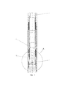
Фиг. 1 - спуск пластыря и расширяющего устройства в ЭК.FIG. 1 - descent of the patch and the expansion device into the EC.
1 - ЭК;1 - EC;
2 - пластырь;2 - a plaster;
3 - гидромеханическое устройство расширения;3 - hydromechanical expansion device;
4 - насосно-компрессорная труба (НКТ).4 - tubing (tubing).
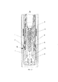
Фиг. 2 - вид А на фиг. 1 в масштабе увеличения (пример конструктивного исполнения устройства расширения).FIG. 2 - view A in FIG. 1 on an enlarged scale (example of a design of an expansion device).
5 - полая тяга (мандрель);5 - hollow rod (mandrel);
6 - конусная оправка;6 - tapered mandrel;
7 - седло сбрасываемой пробки;7 - saddle of the dumped plug;
8 - сбрасываемая пробка;8 - dumped plug;
9 - разбуриваемый башмак;9 - drillable shoe;
10 - обратный клапан;10 - check valve;
11 - наружное уплотнительное кольцо.11 - outer sealing ring.
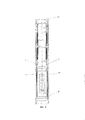
Фиг. 3 - предварительное расширение пластыря в ЭК и закачивание композитной смеси в межтрубное пространство.FIG. 3 - preliminary expansion of the patch in the EC and injection of the composite mixture into the annular space.
12 - тампонирующая композитная смесь.12 - plugging composite mixture.
Заявляемый способ реализуется в оборудовании, включающем гладкий пластырь (2) в виде тонкостенной трубы из стали, имеющей вязко-пластичные характеристики. В случае большой протяженности зоны негерметичности ЭК (1), пластырь (2) может быть выполнен в виде последовательно свинченных между собой отдельных секций (не показаны), имеющих на концах специальную низкопрофильную трапецеидальную резьбу (на рисунках не показана), сохраняющую свои прочностные и герметичные свойства при радиальном расширении всего секционного пластыря. Пластырь (2) имеет снаружи ряд привулканизированных эластичных наружных уплотнительных колец (11) (см. фиг. 2 и 3), например, из набухающей резины. Помимо этого, пластырь (2) имеет снизу местное воронкообразное уширение, наружный диаметр которого обеспечивает гарантированный зазор между ним и стенкой ЭК. В этом уширении герметично закреплен разбуриваемый башмак (9) с обратным клапаном (10) и седлом (7) для сбрасываемой пробки (8). Гидромеханическое устройство расширения (3) (фиг. 1) также расположено в воронкообразном участке пластыря (2) и выполнено в виде жестко закрепленной на полой тяге (мандрели) (5) конусной оправки (6), при этом вершина конуса направлена вверх (см. фиг. 2), а полая тяга (мандрель) (5) соединена с насосной установкой и подъемником бригады капитального ремонта скважин (КРС) (не показаны) посредством колонны насосно-компрессорных труб (НКТ) (4) (фиг. 1). Сбрасываемая пробка (8) (см. фиг. 2) также входит в состав гидромеханического устройства расширения (3). Способ осуществляют следующим образом.The inventive method is implemented in equipment including a smooth plaster (2) in the form of a thin-walled steel pipe having viscous-plastic characteristics. In the case of a large length of the EC leakage zone (1), the plaster (2) can be made in the form of sequentially screwed together separate sections (not shown) having at the ends a special low-profile trapezoidal thread (not shown in the figures), which retains its strength and tightness radial expansion properties of the entire sectional plaster. The patch (2) has on the outside a series of vulcanized elastic outer sealing rings (11) (see FIGS. 2 and 3), for example made of swellable rubber. In addition, the plaster (2) has a local funnel-shaped widening below, the outer diameter of which provides a guaranteed gap between it and the EC wall. In this widening, a drillable shoe (9) with a check valve (10) and a seat (7) for a dumped plug (8) is sealed. The hydromechanical expansion device (3) (Fig. 1) is also located in the funnel-shaped section of the patch (2) and is made in the form of a tapered mandrel (6) rigidly fixed to the hollow rod (mandrel) (5), with the top of the cone directed upward (see. Fig. 2), and the hollow thrust (mandrel) (5) is connected to the pumping unit and the hoist of the well workover crew (KRS) (not shown) by means of a tubing string (tubing) (4) (Fig. 1). The ejected plug (8) (see Fig. 2) is also part of the hydromechanical expansion device (3). The method is carried out as follows.
На колонне НКТ (4) спускают в ЭК (1), в заранее определенный геофизическими исследованиями интервал негерметичности, пластырь (2) с расположенным в его нижней воронкообразном участке гидромеханическим устройством расширения (3) (фиг. 1). Затем инициируют процесс предварительного расширения пластыря (2), осуществив посадку сбрасываемой пробки (8) в седло (7), которое жестко и герметично соединено с разбуриваемым башмаком (9) (фиг. 2), при этом сбрасываемая пробка (8) перекрывает доступ к обратному клапану (10). Вслед за этим по полой тяге (мандрели) (5), соединенной при помощи колонны НКТ (4) со скважинной насосной установкой (не показана) начинают нагнетание рабочей жидкости, которая поступает в полость "Б" и воздействует на конусную оправку (6), выполняющую роль поршня (фиг. 2). Одновременно с этим, с целью облегчения процесса расширения пластыря (2) помимо подачи жидкости под давлением в гидромеханическое устройство расширения (3), к конусной оправке (6) дополнительно прилагается усилие подъемника бригады КРС (не показан) через колонну НКТ (4). Конусная оправка (6) с мандрелью (5) начинают движение вверх, производя расширение пластыря (2), в результате чего последний через наружные уплотнительные кольца (11) (фиг.2 и 4) оказывается герметично прижатым к стенке ЭК (1) (фиг. 3). Процесс предварительного расширения пластыря (2) производят до тех пор, пока гидромеханическое устройство расширения (3) не произведет сжатие первых трех по ходу наружных уплотнительных колец (11) (фиг. 3). Затем предварительное расширение пластыря (2) останавливают и начинают (при помощи продавочной буферной жидкости) закачивание порции тампонирующей композитной смеси (12) (например, на основе смол с отвердителями) в межтрубное пространство НКТ (4) и ЭК (1) до тех пор, пока тампонирующая композитная смесь (12) не заполнит полость между нерасширенной частью пластыря (2) и стенкой ЭК (1). В момент начала отверждения тампонирующей композитной смеси (12) начинают процесс окончательного расширения пластыря (2) до полного выхода конусной оправки (6) за пределы пластыря (2). После этого мандрель (5) с конусной оправкой (6) извлекают на поверхность, а башмак (9) вместе с седлом (7), сбрасываемой пробкой (8) и обратным клапаном (10) разбуривают. В результате расширенный пластырь (2) оказывается плотно прижатым к стенке ЭК (1) через наружные уплотнительные эластичные кольца (11), причем в процессе расширения пластыря (2) часть сохранившей эластичность и не до конца затвердевшей тампонирующей композитной смеси (12) вдавливается в трещины дефектной зоны ЭК (1), закупоривая их. Остальная часть тампонирующей композитной смеси (12) уплотняется расширенным пластырем (2) и после полного отверждения создает вокруг последнего защитный слой, увеличивающий механическую прочность пластыря (2) и предохраняющий его от воздействия агрессивных скважинных жидкостей, что позволяет увеличить срок службы пластыря (2) вплоть до всего срока эксплуатации скважины. Кроме того, упрочнение пластыря (2) слоем затвердевшей композитной смеси (12) и повышение его коррозионной стойкости позволяет уменьшить толщину стенки, что существенно снижает расход металла и энергозатраты на расширение пластыря (2).On the tubing string (4), the plaster (2) with the hydromechanical expansion device (3) located in its lower funnel-shaped section (3) is lowered into the EC (1), into the interval of leaks predetermined by geophysical studies (Fig. 1). Then, the process of preliminary expansion of the patch (2) is initiated by seating the ejected plug (8) into the saddle (7), which is rigidly and hermetically connected to the shoe to be drilled (9) (Fig. 2), while the ejected plug (8) blocks access to check valve (10). Following this, along the hollow rod (mandrel) (5), connected by means of a tubing string (4) with a downhole pumping unit (not shown), the pumping of the working fluid begins, which enters the cavity "B" and acts on the conical mandrel (6), acting as a piston (Fig. 2). At the same time, in order to facilitate the expansion of the patch (2), in addition to supplying liquid under pressure to the hydromechanical expansion device (3), the force of the workover crew lift (not shown) is additionally applied to the cone mandrel (6) through the tubing string (4). The conical mandrel (6) with the mandrel (5) begins to move upward, producing the expansion of the patch (2), as a result of which the latter through the outer sealing rings (11) (Figs. 2 and 4) is hermetically pressed against the EC wall (1) (Fig. . 3). The process of preliminary expansion of the patch (2) is carried out until the hydromechanical expansion device (3) compresses the first three along the outer sealing rings (11) (Fig. 3). Then the preliminary expansion of the patch (2) is stopped and the pumping of a portion of the plugging composite mixture (12) (for example, based on resins with hardeners) into the tubing space (4) and EC (1) is started (with the help of a squeezing buffer fluid) until until the plugging composite mixture (12) fills the cavity between the non-expanded part of the patch (2) and the EC wall (1). At the moment of the beginning of the curing of the plugging composite mixture (12), the process of the final expansion of the patch (2) begins until the conical mandrel (6) fully exits the patch (2). After that, the mandrel (5) with a conical mandrel (6) is removed to the surface, and the shoe (9) together with the seat (7), a dumped plug (8) and a check valve (10) are drilled out. As a result, the expanded plaster (2) turns out to be tightly pressed against the EC wall (1) through the outer elastic sealing rings (11), and during the expansion of the plaster (2), a part of the remaining elastic and not completely hardened plugging composite mixture (12) is pressed into the cracks defective EC zone (1), clogging them. The rest of the plugging composite mixture (12) is compacted with an expanded plaster (2) and, after complete curing, creates a protective layer around the latter, which increases the mechanical strength of the plaster (2) and protects it from the effects of corrosive well fluids, which makes it possible to increase the service life of the plaster (2) up to until the entire life of the well. In addition, strengthening the plaster (2) with a layer of hardened composite mixture (12) and increasing its corrosion resistance makes it possible to reduce the wall thickness, which significantly reduces the metal consumption and energy consumption for expanding the plaster (2).
Таким образом, предлагаемое изобретение позволяет получить способ герметизации эксплуатационных колонн, в котором достигается повышение надежности и эффективности проведения ремонтно-изоляционных работ (РИР) на скважине.Thus, the proposed invention makes it possible to obtain a method for sealing production strings, in which an increase in the reliability and efficiency of repair and isolation works (RIR) at a well is achieved.
Изобретение было раскрыто выше со ссылкой на конкретный вариант его осуществления. Для специалистов могут быть очевидны и иные варианты осуществления изобретения, не меняющие его сущности, раскрытой в настоящем описании. Соответственно, изобретение следует считать ограниченным по объему только нижеследующей формулой изобретения.The invention has been disclosed above with reference to a specific embodiment. Other embodiments of the invention may be obvious to specialists without changing its essence disclosed in the present description. Accordingly, the invention should be considered limited in scope only by the following claims.
Claims (1)
Priority Applications (1)
| Application Number | Priority Date | Filing Date | Title |
|---|---|---|---|
| RU2019109159A RU2737745C2 (en) | 2019-03-29 | 2019-03-29 | Sealing method of production strings of oil and gas wells |
Applications Claiming Priority (1)
| Application Number | Priority Date | Filing Date | Title |
|---|---|---|---|
| RU2019109159A RU2737745C2 (en) | 2019-03-29 | 2019-03-29 | Sealing method of production strings of oil and gas wells |
Publications (3)
| Publication Number | Publication Date |
|---|---|
| RU2019109159A3 RU2019109159A3 (en) | 2020-09-29 |
| RU2019109159A RU2019109159A (en) | 2020-09-29 |
| RU2737745C2 true RU2737745C2 (en) | 2020-12-02 |
Family
ID=72946788
Family Applications (1)
| Application Number | Title | Priority Date | Filing Date |
|---|---|---|---|
| RU2019109159A RU2737745C2 (en) | 2019-03-29 | 2019-03-29 | Sealing method of production strings of oil and gas wells |
Country Status (1)
| Country | Link |
|---|---|
| RU (1) | RU2737745C2 (en) |
Citations (6)
| Publication number | Priority date | Publication date | Assignee | Title |
|---|---|---|---|---|
| SU1270290A1 (en) * | 1984-11-05 | 1986-11-15 | Туркменский государственный научно-исследовательский и проектный институт нефтяной промышленности | Method of repairing leaks of casings |
| WO1989006738A1 (en) * | 1988-01-15 | 1989-07-27 | Charles Koster | A method and apparatus for repairing casing and the like |
| US7082998B2 (en) * | 2003-07-30 | 2006-08-01 | Halliburton Energy Services, Inc. | Systems and methods for placing a braided, tubular sleeve in a well bore |
| RU2484234C1 (en) * | 2011-11-29 | 2013-06-10 | ООО "РН-УфаНИПИнефть" | Well repair method |
| RU2563520C2 (en) * | 2010-02-22 | 2015-09-20 | Веллтек А/С | Tubular assembly |
| RU2629501C1 (en) * | 2016-11-22 | 2017-08-29 | Общество с ограниченной ответственностью "Пласт Инжиниринг" | Equipment for restoration of worn and defective areas of operating columns of oil and gas wells |
-
2019
- 2019-03-29 RU RU2019109159A patent/RU2737745C2/en not_active IP Right Cessation
Patent Citations (6)
| Publication number | Priority date | Publication date | Assignee | Title |
|---|---|---|---|---|
| SU1270290A1 (en) * | 1984-11-05 | 1986-11-15 | Туркменский государственный научно-исследовательский и проектный институт нефтяной промышленности | Method of repairing leaks of casings |
| WO1989006738A1 (en) * | 1988-01-15 | 1989-07-27 | Charles Koster | A method and apparatus for repairing casing and the like |
| US7082998B2 (en) * | 2003-07-30 | 2006-08-01 | Halliburton Energy Services, Inc. | Systems and methods for placing a braided, tubular sleeve in a well bore |
| RU2563520C2 (en) * | 2010-02-22 | 2015-09-20 | Веллтек А/С | Tubular assembly |
| RU2484234C1 (en) * | 2011-11-29 | 2013-06-10 | ООО "РН-УфаНИПИнефть" | Well repair method |
| RU2629501C1 (en) * | 2016-11-22 | 2017-08-29 | Общество с ограниченной ответственностью "Пласт Инжиниринг" | Equipment for restoration of worn and defective areas of operating columns of oil and gas wells |
Non-Patent Citations (1)
| Title |
|---|
| ЧЕРТЕНКОВ М.В. и др. "Опыт применения расширяющихся систем для ликвидации интервалов негерметичности эксплуатационных колонн в ООО "ЛУКОЙЛ -Западная Сибирь", журнал "Бурение и нефть" N 10, 2015, стр. 42-44. * |
Also Published As
| Publication number | Publication date |
|---|---|
| RU2019109159A3 (en) | 2020-09-29 |
| RU2019109159A (en) | 2020-09-29 |
Similar Documents
| Publication | Publication Date | Title |
|---|---|---|
| US7603758B2 (en) | Method of coupling a tubular member | |
| US7861791B2 (en) | High circulation rate packer and setting method for same | |
| US20100319427A1 (en) | Apparatus and method for expanding tubular elements | |
| CA2397480C (en) | Expanding a tubular member | |
| CN104564001B (en) | The method of many cluster pressure breaks of horizontal well and many cluster perforating and fracturing tubing strings of implementation the method | |
| US9714555B2 (en) | Method of plugging a well | |
| OA11859A (en) | Method for annular sealing. | |
| RU2441140C2 (en) | Device for hanger lowering and cementing of casing liner in well | |
| US7363984B2 (en) | System for radially expanding a tubular member | |
| US8201635B2 (en) | Apparatus and methods for expanding tubular elements | |
| AU2016294427A1 (en) | Expandable liner | |
| CN102365419A (en) | Expansion against cement for zonal isolation | |
| CA2432030C (en) | Mono-diameter wellbore casing | |
| CN111425148A (en) | Casing pipe column applying toe end sliding sleeve to full-bore sliding sleeve and using method of casing pipe column | |
| CN108119107A (en) | Liner hanger sets instrument and its application method | |
| RU2737745C2 (en) | Sealing method of production strings of oil and gas wells | |
| CN219101298U (en) | Degradable expansion rubber plug for oil pipe | |
| RU2484240C1 (en) | Installation method of casing string liner in well | |
| RU2629501C1 (en) | Equipment for restoration of worn and defective areas of operating columns of oil and gas wells | |
| EA008134B1 (en) | Continuous monobore liquid lining system | |
| GB2397264A (en) | Expanding a tubular member | |
| CN112282689B (en) | Soluble packer and using method thereof | |
| CA2490786A1 (en) | System for radially expanding a tubular member | |
| US9051789B2 (en) | High collapse resistance solid expandable technology | |
| CN205477511U (en) | Prevent releasing hydraulic fracturing hole sealing device |
Legal Events
| Date | Code | Title | Description |
|---|---|---|---|
| MM4A | The patent is invalid due to non-payment of fees |
Effective date: 20210330 |