RU2731503C2 - Equipment for technical control of main pipeline transition and method of its operation - Google Patents
Equipment for technical control of main pipeline transition and method of its operation Download PDFInfo
- Publication number
- RU2731503C2 RU2731503C2 RU2018145774A RU2018145774A RU2731503C2 RU 2731503 C2 RU2731503 C2 RU 2731503C2 RU 2018145774 A RU2018145774 A RU 2018145774A RU 2018145774 A RU2018145774 A RU 2018145774A RU 2731503 C2 RU2731503 C2 RU 2731503C2
- Authority
- RU
- Russia
- Prior art keywords
- pipeline
- road
- acoustic
- piezoelectric transducers
- antenna arrays
- Prior art date
Links
- 230000007704 transition Effects 0.000 title claims abstract description 11
- 238000000034 method Methods 0.000 title claims description 8
- 238000003491 array Methods 0.000 claims abstract description 14
- 230000001681 protective effect Effects 0.000 claims abstract description 10
- 230000010365 information processing Effects 0.000 claims description 9
- 238000012544 monitoring process Methods 0.000 claims description 7
- 230000000694 effects Effects 0.000 abstract 1
- 239000000126 substance Substances 0.000 abstract 1
- 101150096674 C20L gene Proteins 0.000 description 4
- 102220543923 Protocadherin-10_F16L_mutation Human genes 0.000 description 4
- 101100445889 Vaccinia virus (strain Copenhagen) F16L gene Proteins 0.000 description 4
- 101100445891 Vaccinia virus (strain Western Reserve) VACWR055 gene Proteins 0.000 description 4
- 230000007547 defect Effects 0.000 description 4
- 238000010586 diagram Methods 0.000 description 2
- 230000001427 coherent effect Effects 0.000 description 1
- 231100001261 hazardous Toxicity 0.000 description 1
- 230000001012 protector Effects 0.000 description 1
Images
Classifications
-
- F—MECHANICAL ENGINEERING; LIGHTING; HEATING; WEAPONS; BLASTING
- F17—STORING OR DISTRIBUTING GASES OR LIQUIDS
- F17D—PIPE-LINE SYSTEMS; PIPE-LINES
- F17D5/00—Protection or supervision of installations
- F17D5/02—Preventing, monitoring, or locating loss
- F17D5/06—Preventing, monitoring, or locating loss using electric or acoustic means
-
- G—PHYSICS
- G01—MEASURING; TESTING
- G01N—INVESTIGATING OR ANALYSING MATERIALS BY DETERMINING THEIR CHEMICAL OR PHYSICAL PROPERTIES
- G01N29/00—Investigating or analysing materials by the use of ultrasonic, sonic or infrasonic waves; Visualisation of the interior of objects by transmitting ultrasonic or sonic waves through the object
- G01N29/04—Analysing solids
Landscapes
- Physics & Mathematics (AREA)
- Acoustics & Sound (AREA)
- Engineering & Computer Science (AREA)
- General Physics & Mathematics (AREA)
- Pathology (AREA)
- Analytical Chemistry (AREA)
- Biochemistry (AREA)
- General Health & Medical Sciences (AREA)
- Life Sciences & Earth Sciences (AREA)
- Immunology (AREA)
- Chemical & Material Sciences (AREA)
- Health & Medical Sciences (AREA)
- Mechanical Engineering (AREA)
- General Engineering & Computer Science (AREA)
- Traffic Control Systems (AREA)
- Investigating Or Analyzing Materials By The Use Of Ultrasonic Waves (AREA)
- Geophysics And Detection Of Objects (AREA)
Abstract
Description
Изобретения относятся к трубопроводному транспорту и могут быть использованы для диагностики технического состояния магистральных трубопроводов (МТ) в потенциально опасных местах, например, при переходе МТ через автомобильную и железную дороги.The inventions relate to pipeline transport and can be used to diagnose the technical condition of main pipelines (MT) in potentially hazardous places, for example, when the MT passes through the road and railways.
Известна аппаратура аналогичного назначения с применением датчиков акустической эмиссии, расположенных на МТ и подключенных выходами через пороговые устройства к блоку обработки /RU 2264578, кл. F16L 7/00, F16L 58/00, F17D 5/02, 2005/.Known equipment for a similar purpose using acoustic emission sensors located on the MT and connected through the outputs through the threshold devices to the processing unit / RU 2264578, class.
Недостатком известной системы является невозможность с ее помощью исследования характера повреждения МТ или его защитного кожуха, а значит и принятия правильного решения о техническом состоянии перехода трубопровода через дорогу.The disadvantage of the known system is the impossibility, with its help, of studying the nature of damage to the MT or its protective casing, and hence making the correct decision on the technical state of the pipeline crossing the road.
Известна аппаратура для контроля технического состояния перехода магистрального трубопровода через дорогу, содержащая защитный кожух, две акустические системы, располагаемые на трубопроводе по разные стороны от дороги и подключенные к блоку обработки информации /RU 2433333, кл. F16D 5/00, 2011/.Known equipment for monitoring the technical state of the transition of the main pipeline across the road, containing a protective casing, two acoustic systems located on the pipeline on opposite sides of the road and connected to the information processing unit / RU 2433333, class.
Данная аппаратура принята за прототип. В прототипе акустические системы выполнены в виде датчиков акустической эмиссии, а блок обработки информации выполнен в виде микропроцессора.This equipment is taken as a prototype. In the prototype, acoustic systems are made in the form of acoustic emission sensors, and the information processing unit is made in the form of a microprocessor.
Недостатком прототипа является невозможность с его помощью определения характера дефекта МТ или его защитного кожуха (размеры, форма, азимутальное расположение дефекта и его характеристики по форме и размерам). Это приводит к ошибочному принятию решения о техническом состоянии перехода.The disadvantage of the prototype is the impossibility with its help to determine the nature of the MT defect or its protective casing (size, shape, azimuthal position of the defect and its characteristics in shape and size). This leads to an erroneous decision on the technical state of the transition.
Известен способ работы акустических систем в аппаратуре, заключающийся в подаче на пьезоэлектрические преобразователи аппаратуры импульсного напряжения /RU 2433333, F17D 5/00, 2011; RU 22664578, кл. F16L 7/00, F16L 58/00, F17D 5/02, 2005/.There is a method of operation of acoustic systems in equipment, which consists in supplying pulsed voltage equipment to piezoelectric transducers / RU 2433333,
Любой из известных способов может быть принят за прототип.Any of the known methods can be taken as a prototype.
Недостатками прототипа способа является, помимо малой информативности о техническом состоянии перехода, ограниченность применения способа для сравнительно малой ширины дороги.The disadvantages of the prototype of the method is, in addition to the low information content about the technical state of the transition, the limited application of the method for a relatively small width of the road.
Техническим результатом от применения изобретения в части аппаратуры является устранение недостатка прототипа, то есть повышение информации о техническом состоянии перехода МТ через дорогу.The technical result from the application of the invention in terms of equipment is to eliminate the disadvantage of the prototype, that is, to increase information about the technical state of the MT crossing the road.
Дополнительным техническим результатом в части способа является расширение области применения аппаратуры на более широкие дороги.An additional technical result in terms of the method is the expansion of the field of application of the equipment to wider roads.
Данные технические результаты достигают за счет того, что в аппаратуре для контроля технического состояния перехода магистрального трубопровода через дорогу, содержащей защитный кожух, две акустические системы, располагаемые на трубопроводе по разные стороны от дороги и подключенные к блоку обработки информации, акустические системы выполнены в виде антенных решеток пьезоэлектрических преобразователей, прикрепляемых к открытому участку трубопровода с помощью прижимного устройства до обеспечения сухого акустического контакта пьезоэлектрических преобразователей с наружной поверхностью трубопровода и устройства позиционирования, выполненного в виде пояса с пазами, направленными вдоль образующих трубопровода, причем антенные решетки выполнены в виде съемных модулей пьезоэлектрических преобразователей, установленных в пазы устройства позиционирования, при этом прижимное устройство выполнено в виде магнитопроводов, установленных в съемных модулях антенных решеток, пьезоэлектрические преобразователи в каждом съемном модуле расположены на одинаковом расстоянии друг от друга с пространственным шагом X, а блок обработки информации включает в себя программно-аппаратный комплекс для коммутации и интерпретации данных, а также за счет того, что в способе работы акустических систем в аппаратуре для контроля технического состояния перехода магистрального трубопровода через дорогу на пьезоэлектрические преобразователи подают импульсное напряжение, при этом импульсное напряжение подают на каждый преобразователь съемного модуля начиная с ближнего к центру перехода через интервал времени t=X/c, где с - скорость звука в материале съемного модуля.These technical results are achieved due to the fact that in the equipment for monitoring the technical state of the transition of the main pipeline across the road, containing a protective casing, two acoustic systems located on the pipeline on opposite sides of the road and connected to the information processing unit, the acoustic systems are made in the form of antenna arrays of piezoelectric transducers attached to an open section of the pipeline using a clamping device to ensure dry acoustic contact of piezoelectric transducers with the outer surface of the pipeline and a positioning device made in the form of a belt with grooves directed along the generatrices of the pipeline, and the antenna arrays are made in the form of removable modules of piezoelectric converters installed in the slots of the positioning device, while the clamping device is made in the form of magnetic circuits installed in removable modules of antenna arrays, piezoelectric converters The monitors in each removable module are located at the same distance from each other with a spatial step X, and the information processing unit includes a software and hardware complex for switching and interpreting data, as well as due to the fact that in the way of operation of acoustic systems in equipment for monitoring the technical state of the transition of the main pipeline across the road, a pulsed voltage is applied to the piezoelectric transducers, while the pulse voltage is applied to each transducer of the removable module starting from the one closest to the center of the transition at a time interval t = X / s, where c is the speed of sound in the material of the removable module.
Акустические системы устанавливаются в любой очередности на трубопровод и защитный кожух.Acoustic systems are installed in any order on the pipeline and protective casing.
Изобретение поясняется чертежами.The invention is illustrated by drawings.
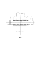
На фиг. 1 представлена схема перехода МТ через дорогу; на фиг. 2, 3, 4, 5 - конструктивная система аппаратуры для контроля технического состояния перехода МТ через дорогу.FIG. 1 shows a diagram of the MT crossing the road; in fig. 2, 3, 4, 5 - a constructive system of equipment for monitoring the technical condition of the MT crossing the road.
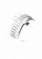
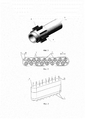
Причем на фиг. 2 представлена схема аппаратуры с антенными решетками преобразователей; на фиг. 3 - эта схема вместе с МТ1; на фиг. 4 и 5 - общий вид антенных решеток соответственно вид сверху и сбоку.Moreover, in FIG. 2 shows a diagram of the equipment with antenna arrays of converters; in fig. 3 - this scheme together with MT1; in fig. 4 and 5 are general views of antenna arrays, top and side views, respectively.
Аппаратура для контроля технического состояния перехода магистрального трубопровода 1 (МТ1) через дорогу 2, содержит защитный кожух 3, через который проходит МТ1 и который располагается под дорогой 2 (фиг. 1).The equipment for monitoring the technical state of the passage of the main pipeline 1 (MT1) across the
На МТ1 и (или) на защитном кожухе 3 симметрично относительно центра 0 пересечения дороги 2 с МТ1 установлены две акустические системы 4 и 5.On MT1 and (or) on the
Акустические системы 4 и 5 выполнены согласно изобретению в виде съемных модулей 6 антенных решеток из пьезоэлектрических преобразователей 7 (фиг. 2, 3, 4, 5). Акустические пьезоэлектрические преобразователи 7 в каждом модуле 6 расположены на расстоянии X друг от друга.
Преобразователи 7 прикрепляются к открытому участку трубопровода 1 или защитного кожуха 3 с помощью прижимного устройства до обеспечения сухого акустического контакта с наружной поверхностью трубы.The
Имеется также устройство 8 позиционирования, выполненное в виде пояса с пазами 9, направленными вдоль образующих трубопровода 1.There is also a
Прижимное устройство выполнено в виде магнитопроводов 10, установленных в съемных модулях 6 антенных решеток.The clamping device is made in the form of
Имеется также блок 11 обработки информации, включающий в себя программно-аппаратный комплекс для коммутации и интерпретации данных, и соединенный проводами с пьезоэлектрическими преобразователями 7.There is also an
Под позицией 13 (фиг. 4) изображены соответственно протекторы, жестко связанные с преобразователями 7 и имеющие электроды 14 (фиг. 5).Under the position 13 (Fig. 4), respectively, protectors are shown, rigidly connected to the
Аппаратура для контроля технического состояния перехода МТ1 через дорогу 2 работает следующим образом.The equipment for monitoring the technical condition of the MT1 crossing across
Акустические системы 4 и 5 устанавливают на трубопроводе 1 или кожух 3 одновременно или последовательно во времени с разных сторон дороги 2. Затем на один из пьезоэлектрических преобразователей 7 каждого съемного модуля 6 антенных решеток одновременно или последовательно подают импульсы напряжения (данная программа работы антенных решеток устанавливается блоком 11 обработки информации).
К центру 0 дороги 2 по трубопроводу 1 или кожуху 3 распространяются ультразвуковые зондирующие импульсы поляризованной поперечной волны. Встречая на своем пути какой-либо дефект трубы (трещину, раковину, каверну и т.п.) ультразвуковая волна частично отражается назад и принимается антенной решеткой. В последней акустический информативный сигнал преобразуется в электрический и направляется в блок 11 обработки информации.Ultrasonic sounding pulses of polarized shear waves propagate to the
По параметрам принятого сигнала определяются координаты, размеры и форму дефекта в виде акустической неоднородности.The parameters of the received signal are used to determine the coordinates, size and shape of a defect in the form of an acoustic inhomogeneity.
Расположение акустических систем 4 и 5 с двух сторон трубопровода 1 и (или) кожуха 3 позволяет в два раза увеличить длину зондируемого участка и довести ее до 60 м.The location of
Если ширина дороги 2 превышает эту величину, то с помощью программно-аппаратного комплекса блока 11 обработки задается программа работы антенных решеток, по которой на пьезоэлектрические преобразователи 7 подаются импульсные напряжения через интервал времени t=Х/c, начиная с ближнего к центру 0 перехода.If the width of the
Такой режим работы акустических антенн позволяет увеличить длину зондирования трубопровода или кожуха за счет увеличения амплитуды зондирующих импульсов путем их когерентного суммирования.Such a mode of operation of acoustic antennas makes it possible to increase the sounding length of a pipeline or casing by increasing the amplitude of the sounding pulses by their coherent summation.
Таким образом, в отличие от прототипа, данная аппаратура и способ позволяют увеличить информацию о техническом состоянии перехода практически для любой ширины дороги.Thus, in contrast to the prototype, this equipment and method can increase information on the technical state of the crossing for almost any width of the road.
Этим достигается поставленный технический результат.This achieves the set technical result.
Claims (2)
Priority Applications (1)
| Application Number | Priority Date | Filing Date | Title |
|---|---|---|---|
| RU2018145774A RU2731503C2 (en) | 2018-12-24 | 2018-12-24 | Equipment for technical control of main pipeline transition and method of its operation |
Applications Claiming Priority (1)
| Application Number | Priority Date | Filing Date | Title |
|---|---|---|---|
| RU2018145774A RU2731503C2 (en) | 2018-12-24 | 2018-12-24 | Equipment for technical control of main pipeline transition and method of its operation |
Publications (3)
| Publication Number | Publication Date |
|---|---|
| RU2018145774A RU2018145774A (en) | 2020-06-25 |
| RU2018145774A3 RU2018145774A3 (en) | 2020-06-25 |
| RU2731503C2 true RU2731503C2 (en) | 2020-09-03 |
Family
ID=71135543
Family Applications (1)
| Application Number | Title | Priority Date | Filing Date |
|---|---|---|---|
| RU2018145774A RU2731503C2 (en) | 2018-12-24 | 2018-12-24 | Equipment for technical control of main pipeline transition and method of its operation |
Country Status (1)
| Country | Link |
|---|---|
| RU (1) | RU2731503C2 (en) |
Citations (6)
| Publication number | Priority date | Publication date | Assignee | Title |
|---|---|---|---|---|
| CN201322742Y (en) * | 2008-09-01 | 2009-10-07 | 中国科学院金属研究所 | Ultrasonic guided wave compound nondestructive testing device |
| RU2433333C2 (en) * | 2009-11-18 | 2011-11-10 | Общество С Ограниченной Ответственностью "Газпромэнергодиагностика" | System to control main pipeline state on road crossing with cathode protection device |
| US20140202249A1 (en) * | 2013-01-23 | 2014-07-24 | General Electric Company | Sensor positionig with non-dispersive guided waves for pipeline corrosion monitoring |
| RU2655991C1 (en) * | 2017-07-13 | 2018-05-30 | Публичное акционерное общество "Газпром" | Apparatus for control of protective insulating coating of technological and main pipelines |
| RU2655982C1 (en) * | 2017-07-13 | 2018-05-30 | Публичное акционерное общество "Газпром" | Equipment for detecting defects of pipelines |
| RU2655983C1 (en) * | 2017-07-13 | 2018-05-30 | Публичное акционерное общество "Газпром" | Method of ultrasound echo-pulse non-destructive control of pipelines and apparatus for its implementation |
-
2018
- 2018-12-24 RU RU2018145774A patent/RU2731503C2/en active
Patent Citations (6)
| Publication number | Priority date | Publication date | Assignee | Title |
|---|---|---|---|---|
| CN201322742Y (en) * | 2008-09-01 | 2009-10-07 | 中国科学院金属研究所 | Ultrasonic guided wave compound nondestructive testing device |
| RU2433333C2 (en) * | 2009-11-18 | 2011-11-10 | Общество С Ограниченной Ответственностью "Газпромэнергодиагностика" | System to control main pipeline state on road crossing with cathode protection device |
| US20140202249A1 (en) * | 2013-01-23 | 2014-07-24 | General Electric Company | Sensor positionig with non-dispersive guided waves for pipeline corrosion monitoring |
| RU2655991C1 (en) * | 2017-07-13 | 2018-05-30 | Публичное акционерное общество "Газпром" | Apparatus for control of protective insulating coating of technological and main pipelines |
| RU2655982C1 (en) * | 2017-07-13 | 2018-05-30 | Публичное акционерное общество "Газпром" | Equipment for detecting defects of pipelines |
| RU2655983C1 (en) * | 2017-07-13 | 2018-05-30 | Публичное акционерное общество "Газпром" | Method of ultrasound echo-pulse non-destructive control of pipelines and apparatus for its implementation |
Also Published As
| Publication number | Publication date |
|---|---|
| RU2018145774A (en) | 2020-06-25 |
| RU2018145774A3 (en) | 2020-06-25 |
Similar Documents
| Publication | Publication Date | Title |
|---|---|---|
| Isla et al. | EMAT phased array: A feasibility study of surface crack detection | |
| KR101061590B1 (en) | Magnetostrictive transducers, structural diagnostic devices and structural diagnostic methods using the same | |
| Kim et al. | Circumferential phased array of shear-horizontal wave magnetostrictive patch transducers for pipe inspection | |
| CN105021715B (en) | A kind of array omni-directional horizontal shear mode magneto strictive sensor | |
| MX2020007613A (en) | Systems and methods for generating ultrasonic waves, exciting special classes of ultrasonic transducers and ultrasonic devices for engineering measurements. | |
| CN104198594A (en) | Multiple-main-frequency combined torsional-mode electromagnetic acoustic array sensor | |
| WO2014190268A1 (en) | Flexural modes in non-destructive testing and inspection | |
| CN108132305A (en) | A kind of method and apparatus of transducer array element performance test | |
| RU2629896C1 (en) | Method of ultrasonic control of pipeline and system for its implementation | |
| RU2655982C1 (en) | Equipment for detecting defects of pipelines | |
| Reyes et al. | A numerical study on baseline-free damage detection using frequency steerable acoustic transducers | |
| US9213019B2 (en) | Method of determining a size of a defect using an ultrasonic linear phased array | |
| RU2731503C2 (en) | Equipment for technical control of main pipeline transition and method of its operation | |
| RU2655983C1 (en) | Method of ultrasound echo-pulse non-destructive control of pipelines and apparatus for its implementation | |
| US20060173341A1 (en) | Electromagnetic ultrasound converter | |
| CN113640391A (en) | Periodic Magnet Flexible Electromagnetic Ultrasound Probe | |
| US20200182720A1 (en) | Device for inspecting clamping means by ultrasounds and method implementing the device | |
| KR102043158B1 (en) | Pipe monitoring apparatus and method | |
| Movahed et al. | Air ultrasonic signal localization with a beamforming microphone array | |
| RU2655991C1 (en) | Apparatus for control of protective insulating coating of technological and main pipelines | |
| US8058776B1 (en) | Laminar array ultrasound transducer and system | |
| Eremin et al. | Localization of inhomogeneities in an elastic plate using the time reversal method | |
| JP7332397B2 (en) | Laser bonding inspection calibration system | |
| Thomas et al. | Self focusing on extended objects with time reversal mirror, applications to lithotripsy | |
| Baravelli et al. | Inkjet fabrication of spiral frequency-steerable acoustic transducers (FSATs) |