RU2729607C2 - System using cellular telephone communication networks for operation of unmanned aerial vehicles and remotely piloted aircraft, as well as for control and communication with similar aircraft - Google Patents
System using cellular telephone communication networks for operation of unmanned aerial vehicles and remotely piloted aircraft, as well as for control and communication with similar aircraft Download PDFInfo
- Publication number
- RU2729607C2 RU2729607C2 RU2018108416A RU2018108416A RU2729607C2 RU 2729607 C2 RU2729607 C2 RU 2729607C2 RU 2018108416 A RU2018108416 A RU 2018108416A RU 2018108416 A RU2018108416 A RU 2018108416A RU 2729607 C2 RU2729607 C2 RU 2729607C2
- Authority
- RU
- Russia
- Prior art keywords
- sky
- directed
- communication
- signals
- layer
- Prior art date
Links
Images


Classifications
-
- H—ELECTRICITY
- H04—ELECTRIC COMMUNICATION TECHNIQUE
- H04W—WIRELESS COMMUNICATION NETWORKS
- H04W12/00—Security arrangements; Authentication; Protecting privacy or anonymity
- H04W12/08—Access security
-
- H—ELECTRICITY
- H04—ELECTRIC COMMUNICATION TECHNIQUE
- H04B—TRANSMISSION
- H04B7/00—Radio transmission systems, i.e. using radiation field
- H04B7/14—Relay systems
- H04B7/15—Active relay systems
- H04B7/185—Space-based or airborne stations; Stations for satellite systems
- H04B7/18502—Airborne stations
- H04B7/18506—Communications with or from aircraft, i.e. aeronautical mobile service
- H04B7/18508—Communications with or from aircraft, i.e. aeronautical mobile service with satellite system used as relay, i.e. aeronautical mobile satellite service
-
- H—ELECTRICITY
- H04—ELECTRIC COMMUNICATION TECHNIQUE
- H04B—TRANSMISSION
- H04B7/00—Radio transmission systems, i.e. using radiation field
- H04B7/14—Relay systems
- H04B7/15—Active relay systems
- H04B7/185—Space-based or airborne stations; Stations for satellite systems
- H04B7/18502—Airborne stations
- H04B7/18504—Aircraft used as relay or high altitude atmospheric platform
-
- H—ELECTRICITY
- H04—ELECTRIC COMMUNICATION TECHNIQUE
- H04B—TRANSMISSION
- H04B7/00—Radio transmission systems, i.e. using radiation field
- H04B7/14—Relay systems
- H04B7/15—Active relay systems
- H04B7/185—Space-based or airborne stations; Stations for satellite systems
- H04B7/18502—Airborne stations
- H04B7/18506—Communications with or from aircraft, i.e. aeronautical mobile service
-
- H—ELECTRICITY
- H04—ELECTRIC COMMUNICATION TECHNIQUE
- H04B—TRANSMISSION
- H04B7/00—Radio transmission systems, i.e. using radiation field
- H04B7/14—Relay systems
- H04B7/15—Active relay systems
- H04B7/185—Space-based or airborne stations; Stations for satellite systems
- H04B7/1853—Satellite systems for providing telephony service to a mobile station, i.e. mobile satellite service
- H04B7/18532—Arrangements for managing transmission, i.e. for transporting data or a signalling message
- H04B7/18534—Arrangements for managing transmission, i.e. for transporting data or a signalling message for enhancing link reliablility, e.g. satellites diversity
-
- H—ELECTRICITY
- H04—ELECTRIC COMMUNICATION TECHNIQUE
- H04W—WIRELESS COMMUNICATION NETWORKS
- H04W16/00—Network planning, e.g. coverage or traffic planning tools; Network deployment, e.g. resource partitioning or cells structures
- H04W16/24—Cell structures
- H04W16/28—Cell structures using beam steering
-
- H—ELECTRICITY
- H04—ELECTRIC COMMUNICATION TECHNIQUE
- H04W—WIRELESS COMMUNICATION NETWORKS
- H04W16/00—Network planning, e.g. coverage or traffic planning tools; Network deployment, e.g. resource partitioning or cells structures
- H04W16/24—Cell structures
- H04W16/30—Special cell shapes, e.g. doughnuts or ring cells
-
- H—ELECTRICITY
- H04—ELECTRIC COMMUNICATION TECHNIQUE
- H04W—WIRELESS COMMUNICATION NETWORKS
- H04W4/00—Services specially adapted for wireless communication networks; Facilities therefor
- H04W4/30—Services specially adapted for particular environments, situations or purposes
- H04W4/40—Services specially adapted for particular environments, situations or purposes for vehicles, e.g. vehicle-to-pedestrians [V2P]
- H04W4/42—Services specially adapted for particular environments, situations or purposes for vehicles, e.g. vehicle-to-pedestrians [V2P] for mass transport vehicles, e.g. buses, trains or aircraft
-
- H—ELECTRICITY
- H01—ELECTRIC ELEMENTS
- H01Q—ANTENNAS, i.e. RADIO AERIALS
- H01Q1/00—Details of, or arrangements associated with, antennas
- H01Q1/12—Supports; Mounting means
- H01Q1/22—Supports; Mounting means by structural association with other equipment or articles
- H01Q1/24—Supports; Mounting means by structural association with other equipment or articles with receiving set
- H01Q1/241—Supports; Mounting means by structural association with other equipment or articles with receiving set used in mobile communications, e.g. GSM
- H01Q1/246—Supports; Mounting means by structural association with other equipment or articles with receiving set used in mobile communications, e.g. GSM specially adapted for base stations
-
- H—ELECTRICITY
- H04—ELECTRIC COMMUNICATION TECHNIQUE
- H04L—TRANSMISSION OF DIGITAL INFORMATION, e.g. TELEGRAPHIC COMMUNICATION
- H04L69/00—Network arrangements, protocols or services independent of the application payload and not provided for in the other groups of this subclass
- H04L69/18—Multiprotocol handlers, e.g. single devices capable of handling multiple protocols
-
- H—ELECTRICITY
- H04—ELECTRIC COMMUNICATION TECHNIQUE
- H04W—WIRELESS COMMUNICATION NETWORKS
- H04W4/00—Services specially adapted for wireless communication networks; Facilities therefor
- H04W4/02—Services making use of location information
- H04W4/021—Services related to particular areas, e.g. point of interest [POI] services, venue services or geofences
-
- H—ELECTRICITY
- H04—ELECTRIC COMMUNICATION TECHNIQUE
- H04W—WIRELESS COMMUNICATION NETWORKS
- H04W4/00—Services specially adapted for wireless communication networks; Facilities therefor
- H04W4/30—Services specially adapted for particular environments, situations or purposes
- H04W4/40—Services specially adapted for particular environments, situations or purposes for vehicles, e.g. vehicle-to-pedestrians [V2P]
- H04W4/46—Services specially adapted for particular environments, situations or purposes for vehicles, e.g. vehicle-to-pedestrians [V2P] for vehicle-to-vehicle communication [V2V]
Abstract
Description
Предпосылки создания изобретенияBackground of the invention
1. Область техники1. Field of technology
Изобретение относится к области беспроводной связи, а конкретнее - к системам, способам и компонентам, предназначенным для эксплуатации сетей сотовой телефонной связи совместно с беспилотными и дистанционно пилотируемыми летательными аппаратами.The invention relates to the field of wireless communications, and more specifically to systems, methods and components designed for the operation of cellular telephone networks in conjunction with unmanned and remotely piloted aircraft.
2. Краткое описание уровня техники2. Brief description of the prior art
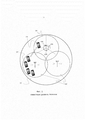
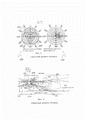
Беспроводные системы общедоступной связи, используемые в настоящее время, часто основаны на "сотовом" принципе, как показано на схеме Фиг. 1. В подобных системах мобильные телефоны или мобильные устройства (100), находящиеся в пределах значительной по площади географической области (101), обслуживаются путем распределения неподвижно установленных местных приемопередающих радиостанций, которые обеспечивают двустороннюю беспроводную связь с устройствами, находящимися в меньших подобластях более крупной области (102). Когда мобильный телефон или мобильное устройство перемещаются из одного места в новое место (103), они могут быть обслужены другой местной неподвижной приемопередающей радиостанцией с системе (104) сотовой беспроводной связи (или другим сектором (104а, 104в, 104с) в пределах дальности действия той же местной неподвижной приемопередающей радиостанции. Диаграммы направленности излучения антенны приемопередающих радиостанций в беспроводной системе типично ориентированы таким образом, чтобы излучение было направлено вдоль поверхности земли, в противоположность всенаправленным или направленным в небо антеннам. Некоторые причины для подобного ограничения диаграммы направленности излучения включают: во-первых, то, что местонахождение пользователей беспроводных устройств в таких системах ограничено почти всегда физически зоной, проходящей вдоль поверхности земли, поскольку беспроводная связь посредством сотовых телефонов и смартфонов из гражданских самолетов, как правило запрещена по закону, и, во-вторых, то, что основанные на сотовом принципе системы связи предотвращают возникновение взаимного влияния между ячейками, в которых повторяется использование частот, путем ограничения мощности излучения, которое может войти в соединение или расположенные поблизости ячейки, что осуществляется, по крайней мере частично, путем управления диаграммой направленности излучения, которую создает антенна, принадлежащая неподвижно установленной приемопередающей радиостанции. Упрощенная схема диаграммы направленности излучения типичной неподвижно установленной приемопередающей радиостанции в системе беспроводной связи, основанной на сотовом принципе, представлена на Фиг. 2. Горизонтальная или "параллельная плоскости земли" диаграмма направленности обозначена позицией (200), а вертикальная диаграмма направленности обозначена позицией (210).Public wireless communication systems in use today are often based on a "cellular" principle, as shown in the diagram of FIG. 1. In such systems, mobile phones or mobile devices (100) located within a significant geographic area (101) are served by allocating fixed local transceiver radios that provide two-way wireless communication with devices located in smaller sub-areas of a larger area (102). When a mobile phone or mobile device moves from one location to a new location (103), it can be served by another local fixed radio transceiver station (104) with a cellular wireless communication system (or another sector (104a, 104b, 104c) within the range of that a local stationary transceiver station. The radiation patterns of the antenna of the radio transmit / receive stations in a wireless system are typically oriented so that the radiation is directed along the surface of the earth, as opposed to omnidirectional or sky-directed antennas.Some reasons for such a limitation of the radiation pattern include: first the fact that the location of users of wireless devices in such systems is almost always physically limited to the area along the surface of the earth, since wireless communication via cell phones and smartphones from civil aircraft is generally prohibited by law, and and secondly, that cellular communication systems prevent interference between cells in which frequency use is repeated by limiting the power of radiation that can enter the connection or nearby cells, at least in part, by controlling the radiation pattern created by an antenna belonging to a fixedly installed transceiver radio station. A simplified diagram of the radiation pattern of a typical fixedly mounted radio transceiver in a cellular wireless communication system is shown in FIG. 2. The horizontal or "parallel to the ground" pattern is indicated by (200) and the vertical pattern is indicated by (210).
При дальнейшем рассмотрении рисунка на Фиг. 3 видно, как можно наглядно изобразить вертикальную диаграмму направленности. Антенная система (300) неподвижной приемопередающей радиостанции сотовой связи обычно устанавливается на мачте на некоторой высоте над поверхностью земли (304) и построена таким образом, чтобы она могла поддерживать связь с мобильными устройствами, находящимся от нее в пределах некоторого радиуса действия антенны (303), путем покрытия этой области так называемым главным лепестком (301) диаграммы направленности с определенными частотами, которые используются для приема и передачи речевого трафика и трафика блоков информации между мобильными устройствами (не показано) и системой связи, основанной на сотовом принципе, посредством неподвижной системы (300). Главный лепесток диаграммы направленности рассчитан таким образом, чтобы он был ограничен полезным углом от 5 до 10 градусов (302), а также мог иметь наклон в сторону земли на дополнительные от 5 до 10 градусов (305). Так называемые вертикальные боковые лепестки, которые направлены к земле, фактически способствуют обеспечению зоны уверенного приема для мобильных устройств вблизи антенны (306а) в то время, как вертикальные боковые лепестки, направленные в сторону неба (306b), обычно не имеют использования или последствий, и ими пренебрегают как побочным продуктом антенной системы.Upon further examination of the figure in FIG. 3 shows how the vertical directional pattern can be clearly depicted. Antenna system (300) of a fixed transceiver radio station of cellular communication is usually installed on a mast at a certain height above the earth's surface (304) and is constructed in such a way that it can communicate with mobile devices located from it within a certain range of the antenna (303), by covering this area with the so-called main lobe (301) of the radiation pattern with certain frequencies, which are used for receiving and transmitting voice traffic and traffic of blocks of information between mobile devices (not shown) and a communication system based on the cellular principle, through a fixed system (300 ). The main lobe is designed to be limited to a useful angle of 5 to 10 degrees (302) and can also be tilted towards the ground by an additional 5 to 10 degrees (305). The so-called vertical side-lobes, which are directed towards the ground, actually contribute to the coverage of mobile devices near the antenna (306a), while the vertical side-lobes directed towards the sky (306b) usually have no use or effect, and they are neglected as a by-product of the antenna system.
На Фиг. 4 показана (позиция 400а) упрощенная схема антенны неподвижной приемопередающей радиостанции, изображенной на Фиг. 3, в которой каждая антенна (401, 402) установлена над поверхностью земли (410) и имеет вертикальную диаграмму направленности излучения, ориентированную существенно вдоль поверхности земли (401а, 401b, 402а, 402b), и при этом неподвижные приемопередающие радиостанции разнесены друг от друга на некотором расстоянии в соответствии с определенным планом, что может иметь место в типичной сотовой сети связи с целью обеспечить неразрывность зоны уверенного приема. Как должно быть совершенно понятно специалистам в этой области, в действительности распределение неподвижно установленных приемопередающих радиостанций осуществляется в двух направленных по поверхности области, на которой требуется обеспечить уверенный прием, и порядок повторного использования частот устанавливается таким образом, чтобы частоты, излучаемые одной неподвижной приемопередающей радиостанцией (401b) в направлении другой (402а), отличались друг от друга, что позволяет избежать помех вследствие взаимного влияния соседних станций. То есть, частоты для связи, соответствующие радиолучу (401b) могут быть из группы частот fA, а частоты, соответствующие радиолучу (402а) могут быть из группы частот fB и так далее. Порядок повторного использования частот в сотовой системе связи хорошо изучен и часто связан с направленностью антенн (401, 402) в горизонтальном направлении, что отмечено на Фиг. 1 позициями (104а, 104b, 104с), а также отмечено на Фиг. 2 позициями (201, 202, 203), в добавление к простому разносу частоты, что представлено на Фиг. 4 (401а, 401b, 402а, 402b).FIG. 4 shows (400a) a simplified diagram of the antenna of the fixed radio transceiver shown in FIG. 3, in which each antenna (401, 402) is installed above the surface of the earth (410) and has a vertical radiation pattern oriented substantially along the surface of the earth (401a, 401b, 402a, 402b), and while the stationary transceiver radio stations are spaced apart from each other at some distance in accordance with a certain plan, which may occur in a typical cellular communication network in order to ensure the continuity of the coverage area. As it should be perfectly clear to specialists in this field, in reality, the distribution of fixedly installed transceiver radio stations is carried out in two surface-directed areas in which reliable reception is required, and the order of frequency reuse is set in such a way that the frequencies emitted by one fixed transceiver radio station ( 401b) in the direction of the other (402a) were different from each other, which avoids interference due to the mutual influence of neighboring stations. That is, the frequencies for communication corresponding to the radio beam (401b) may be from the frequency group f A , and the frequencies corresponding to the radio beam (402a) may be from the frequency group f B, and so on. Frequency reuse in a cellular communication system is well understood and is often associated with the directionality of the antennas (401, 402) in the horizontal direction, as noted in FIG. 1 by reference numbers (104a, 104b, 104c) and also indicated in FIG. 2 at (201, 202, 203), in addition to the simple frequency spacing shown in FIG. 4 (401a, 401b, 402a, 402b).
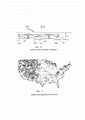
Упрощенная ситуация, изображенная на Фиг. 4, была повторена в двух измерениях в населенных в настоящее время областях мира таким образом, что были созданы крупные регионы и даже целые страны, в которых имеется практически непрерывная зона, или слой (421) уверенного приема, расположенный вблизи поверхности земли, в котором при самых неблагоприятных погодных условиях можно поддерживать надежную связь между устройством и сотовой системой, и далее с последующими конечными пунктами, соединенными с сотовой системой (такими, как коммутируемая сеть телефонной связи общего пользования, другие мобильные устройства или компьютерные системы, обменивающиеся блоками информации с мобильными устройствами с сети сотовой связи). На Фиг. 5 представлена так называемая карта зон уверенного приема на территории Соединенных Штатов, на которой синие области представляют собой области, в которых обеспечена непрерывная зона уверенного приема в сети сотовой связи, способная пропускать как речевой трафик, так и трафик потока данных к мобильным устройствам, расположенным вблизи земли, и от них, а белые области соответствуют зонам с отсутствием устойчивого приема. Из простого наблюдения с очевидностью следует, что большая часть территории США является зоной устойчивого приема.The simplified situation depicted in FIG. 4 was repeated in two dimensions in currently populated areas of the world in such a way that large regions and even entire countries were created in which there is a practically continuous zone, or a layer (421) of reliable reception located near the surface of the earth, in which, In the most adverse weather conditions, reliable communication can be maintained between the device and the cellular system, and then with subsequent endpoints connected to the cellular system (such as a public switched telephone network, other mobile devices or computer systems that exchange blocks of information with mobile devices with cellular networks). FIG. 5 shows the so-called coverage area map in the United States, in which the blue areas represent areas in which a continuous coverage area of the cellular network is provided, capable of transmitting both voice traffic and data traffic to mobile devices located nearby. land, and away from them, and the white areas correspond to areas with no stable reception. From a simple observation, it clearly follows that most of the United States is a zone of stable reception.
В настоящее время имеется огромный интерес к использованию беспилотных летательных аппаратов (в дальнейшем БЛА) и дистанционного пилотируемых летательных аппаратов (в дальнейшем ДПЛА) для хозяйственной деятельности. Этот интерес включает самые различные функции: от доставки пакетов на большие расстояния из склада, занимающегося распределением товаров в округе, до дистанционного зондирования 1000 миль труб нефтепровода для обнаружения возможных утечек или вторжений на полосу отчуждения.Currently, there is great interest in the use of unmanned aerial vehicles (hereinafter UAVs) and remotely piloted aerial vehicles (hereinafter RPVs) for economic activities. This interest includes a variety of functions, from delivering packages over long distances from a warehouse that distributes goods in a district to remotely sensing 1,000 miles of oil pipelines to detect possible leaks or intrusions into the right of way.
Для удобства обсуждения в данном описании, но при этом без потери универсальности и понимая, что может быть существенное пересечение между этими двумя категориями ЛА, к БЛА будем относить летающие на короткие расстояния и на небольшой высоте ЛА, имеющие вес менее 50 футов, которые летают не выше 2000 футов над поверхностью земли и/или ниже контролируемого согласно закону воздушного пространства и могут иметь или не иметь удаленного оператора, активно управляющего БЛА на протяжении части полета или всего полета, при этом оставшаяся часть полета может выполняться при автономном управлении, а к ДПЛА будем относить летающие на большие расстояния и на большей высоте ЛА, имеющие вес более 50 футов с типичной нормальной высотой полета, превышающей 2000 футов над поверхностью земли и/или в пределах контролируемого согласно закону воздушного пространства, и всегда имеющие человека, дистанционно пилотирующего и/или контролирующего ЛА, с возможностью автоматизации нормального курса полета, подобно тому, как использование автопилота является обычным в пилотируемых воздушных судах.For convenience of discussion in this description, but at the same time without loss of versatility and understanding that there may be a significant intersection between these two categories of aircraft, UAVs will include aircraft flying at short distances and at low altitude, having a weight less than 50 feet, which do not fly above 2000 feet above the ground and / or below the airspace controlled according to the law and may or may not have a remote operator actively controlling the UAV during part of the flight or the entire flight, while the rest of the flight can be performed with autonomous control, and we will include aircraft flying over long distances and at higher altitudes, which weigh more than 50 feet and have a typical normal flight altitude exceeding 2000 feet above the ground and / or within legally controlled airspace, and always have a person remotely piloting and / or controlling Aircraft, with the ability to automate the normal course of flight, similar how the autopilot is common on manned aircraft.
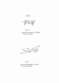
Типичный БЛА и типичный ДПЛА показаны на Фиг. 6 и 7 соответственно. БЛА и ДПЛА первоначально были разработаны главным образом для военных целей и поэтому для связи с ними принципиально использовались способы военной связи: связь в пределах прямой видимости для БЛА и военные спутниковые сети для ДПЛА. Пример конфигурации сети связи для многих современных военных ДПЛА представлен на Фиг. 8, на которой показано, что БЛА/ДПЛА при указанном военном использовании устанавливает связь в первую очередь исключительно с находящимися над ними выделенными спутниками (801), которые затем передают информацию в командный центр (810). Фактически, как показано на Фиг. 9, носовая часть ДПЛА, изображенного на Фиг. 7, выделена главным образом для размещения следящей антенны с высоким коэффициентом направленного действия, которая имеет связь со спутниками, вращающимися по орбите над ДПЛА на высоте от 650 до 22500 миль. Потери сигнала на трассе распространения, сопутствующие связи с приемо-передатчиком или транспондером на таких расстояниях, приводят к необходимости иметь антенны с высоким коэффициентом направленного действия, как показано на Фиг. 9 (901).A typical UAV and a typical RPV are shown in FIG. 6 and 7 respectively. UAVs and RPVs were originally developed mainly for military purposes, and therefore military communication methods were fundamentally used for communication with them: line-of-sight communication for UAVs and military satellite networks for RPVs. An example of a communication network configuration for many modern military UAVs is shown in FIG. 8, which shows that the UAV / RPV, with the specified military use, establishes communication primarily exclusively with dedicated satellites located above them (801), which then transmit information to the command center (810). In fact, as shown in FIG. 9, the nose of the RPV shown in FIG. 7 is dedicated primarily to the placement of a highly directional tracking antenna that communicates with satellites orbiting above the RPV between 650 and 22,500 miles. The signal loss along the propagation path associated with communications with the transceiver or transponder at such distances leads to the need for antennas with high directivity, as shown in FIG. 9 (901).
Для того, чтобы ДПЛА, и в некоторой степени БЛА, могли быть использованы для хозяйственной деятельности, в большинстве юрисдикции они должны соответствовать законам и правилам, регулирующим использование контролируемого диспетчерами воздушного пространства. В общем случае для такого соответствия требуется, чтобы БЛА/ДПЛА могли устанавливать связь с диспетчерской службой управления воздушным движением, а также видеть других участников воздушного движения и уклоняться от них. Таким образом, помимо блоков информации в реальном времени, которые для хозяйственной деятельности необходимо пересылать между БЛА/ДПЛА и их центрами управления, ДПЛА должен поддерживать постоянную связь со своим центром управления для того, чтобы передавать изображения, полученные ДПЛА, и сообщения, которыми обмениваются и центр управления воздушным движением с тем, чтобы ДПЛА мог действовать и/или им можно было управлять, как если бы он был пилотируемым воздушным судном.In order for RPVs, and to some extent UAVs, to be used for business activities, in most jurisdictions they must comply with the laws and regulations governing the use of airspace controlled by dispatchers. In general, such compliance requires that UAVs / RPVs be able to communicate with the air traffic control service, as well as see and evade other air traffic participants. Thus, in addition to blocks of information in real time, which for economic activities must be sent between the UAV / RPV and their control centers, the RPV must maintain constant communication with its control center in order to transmit images received by the RPV and messages that are exchanged and an air traffic control center so that the UAV can operate and / or be controlled as if it were a manned aircraft.
Необходимость постоянного поддержания связи предъявляет значительные требования к каналу связи с находящимися на орбите спутниками. Помимо сложности со связью на такие расстояния (от 650 до 22500 миль), имеется только ограниченное количество доступных спутников, каждый из которых имеет ограниченную ширину полосы частот, при этом не достаточны как их количество, так и рабочая полоса частот, чтобы соответствовать значительной хозяйственной деятельности с участием ДПЛА и БЛА. Кроме того, небольшие по размеру ДПЛА и БЛА не имеют достаточно места или возможности нести полезный груз для размещения антенной системы, необходимой для связи с ДПЛА или БЛА со спутниками. Кроме того, полностью отсутствует или имеется незначительный резерв спутников, и если транспондер на спутнике выйдет из строя и/или связь через этот спутник будет нарушена, то любая связь с ДПЛА/БЛА может быть потеряна и, следовательно, может быть потеряно управление ДПЛА/БЛА.The need for continuous communication makes significant demands on the communication channel with satellites in orbit. In addition to the difficulty of communicating over such distances (650 to 22,500 miles), there are only a limited number of satellites available, each with limited bandwidth, and both the number and operating bandwidth are not sufficient to accommodate significant economic activity. with the participation of RPV and UAV. In addition, small-sized UAVs and UAVs do not have enough space or the ability to carry a payload to accommodate the antenna system necessary for communication with UAVs or UAVs with satellites. In addition, there is completely no or a small reserve of satellites, and if the transponder on the satellite fails and / or communication through this satellite is disrupted, then any communication with the RPV / UAV may be lost and, therefore, control of the RPV / UAV may be lost. ...
Краткое изложение сущности изобретенияSummary of the invention
В данном изобретении предлагается система, способ и компоненты для координации и эксплуатации надежной связи с самыми различными ДПЛА/БЛА. Варианты выполнения системы имеют конфигурацию, позволяющую обеспечить зону устойчивого приема с перекрытием особенно в густонаселенных областях, в которых управление ДПЛА/БЛА и связь с ними особенно важны из соображений безопасности. Данное изобретение представляет собой усовершенствование ограниченной в настоящее время современной сотовой сети для передачи данных речи, которая в настоящее время ограничена работой вблизи поверхности земли.The present invention provides a system, method, and components for coordinating and operating reliable communications with a wide variety of RPVs / UAVs. System embodiments are configured to provide a stable coverage area with overlapping, especially in densely populated areas, in which control and communication of UAVs / UAVs are especially important for safety reasons. This invention is an improvement on the currently limited cellular network for voice data transmission, which is currently limited to operation near the earth's surface.
Согласно некоторым предпочтительным вариантам выполнения, предлагается система связи сотового типа. Система имеет конфигурацию, позволяющую создать первую область для связи с устройствами, находящимися вблизи поверхности земли. Дополнительные слои такие как, например, один или более, чем один второй слой создаются, с покрытием приблизительно той же самой области, что и первая приземная область, но они отделены друг от друга, а также они расположены существенно выше поверхности земли. Система имеет конфигурацию, позволяющую создать вторую или дополнительную, расположенную выше поверхности земли область, или слой, которые должны служить областью, в пределах которой воздушное судно может быть обеспечено надежной связью с использование сотовой сети связи. Следовательно, сотовая сеть обслуживает передаваемые сообщения вблизи поверхности земли через первую приземную область, а связь с небом происходит через вторую, или расположенную выше поверхности земли область или области. Предпочтительно уровни отделяются друг от друга, что можно физически осуществить путем использования экранов таких, как, например, пассивные рефлекторы. Кроме того, или в качестве альтернативы, приемопередатчики устройств связи, т.е. устройств, расположенных вблизи земли, и летательных аппаратов таких, как ДПЛА или БЛА могут быть сконструированы таким образом, чтобы они работали с использованием различных протоколов с тем, чтобы в случае попыток установить связь во второй области с использованием устройства, предназначенного для приземного использования, они не повлияли на работу связи на втором уровне воздушного пространства. Например, протокол связи с объектами в небе, может отличаться от протокола связи вдоль поверхности земли с тем, чтобы уникальным образом идентифицировать приемопередатчики БЛА и ДПЛА и отличить их от расположенных на поверхности земли сотовых телефонов, смартфонов и подобных устройств.In some preferred embodiments, a cellular communication system is provided. The system is configured to create a first area for communication with devices near the surface of the earth. Additional layers such as, for example, one or more than one second layer are created, covering approximately the same area as the first surface area, but they are separated from each other, and they are located significantly above the surface of the earth. The system is configured to provide a second or additional above ground area or layer to serve as an area within which the aircraft can be reliably communicated using a cellular network. Consequently, the cellular network serves the transmitted messages near the surface of the earth through the first surface area, and communication with the sky occurs through the second, or located above the earth's surface area or areas. Preferably, the levels are separated from each other, which can be physically accomplished by using screens such as passive reflectors. In addition, or alternatively, communication device transceivers, i. E. devices located near the ground, and aircraft such as RPVs or UAVs, can be designed to operate using different protocols so that in the event of attempts to establish communication in a second area using a device intended for surface use, they did not affect the operation of communications at the second level of airspace. For example, the protocol for communication with objects in the sky may differ from the communication protocol along the surface of the earth in order to uniquely identify the transceivers of UAVs and RPVs and distinguish them from cell phones, smartphones and similar devices located on the surface of the earth.
Для того, чтобы реализовать предпочтительные варианты выполнения этого изобретения, конфигурацию настоящей системы можно осуществить путем развертывания антенной системы, устанавливаемой на существующее опорное устройство неподвижной приемопередающей антенны базовой станции сотовой сети. Предпочтительно антенная система представляет собой направленную в небо антенну и имеет конфигурацию, позволяющую ей излучать энергию в радиочастотном диапазоне в сторону неба. Согласно предпочтительным вариантам выполнения, излучение заданной частоты распространяется в пределах некоторого телесного угла в виде конуса или тела иной формы. Согласно некоторым вариантам выполнения, антенная система может быть соединена со вторым комплектом приемопередающего оборудования, подобным или таким же, как и существующее оборудование сотовой сети, и она осуществляет связь с находящимся в воздухе летательными аппаратами (например, с БЛА и ДПЛА), а не связь вдоль поверхности земли.In order to implement the preferred embodiments of this invention, the configuration of the present system may be accomplished by deploying an antenna system to be installed on an existing fixed transceiver antenna support of a base station of a cellular network. Preferably, the antenna system is a sky-directed antenna and is configured to radiate RF energy towards the sky. According to preferred embodiments, the radiation of a given frequency propagates within a solid angle in the form of a cone or a different body. In some embodiments, the antenna system can be connected to a second set of transceiver equipment, similar or the same as existing cellular network equipment, and it communicates with aircraft in the air (for example, UAVs and RPVs), rather than communication along the surface of the earth.
Согласно предпочтительным вариантам выполнения, сигналы, посылаемые в небо направленными в небо антеннами, являются поляризованными; причем предпочтительно они имеют горизонтальную или круговую поляризацию. Согласно некоторым предпочтительным вариантам выполнения, в сторону неба излучается две группы сигналов с различающимися группами частот, при этом углы, ограниченные диаграммой направленности излучения, отличаются друг от друга для того, чтобы создать сплошную область устойчивой связи для зон, находящихся на разной высоте над антенной. Например, первый угол расхождения диаграммы направленности излучения может простираться в сторону неба и представлять область частот, которые должен использовать для связи первый тип летательного аппарата. Им может быть БЛА, которые типично работают на более низких уровнях по сравнению ДПЛА. В этом примере вторая область частот может быть обеспечена посредством второй диаграммы направленности излучения, имеющей другой угол расхождения, что позволяет создать область для связи с ДПЛА. Различающиеся зоны по высоте могут представлять собой вторые слои небесной области.In preferred embodiments, the signals sent into the sky by the sky-directed antennas are polarized; and preferably they are horizontally or circularly polarized. According to some preferred embodiments, two groups of signals with different frequency groups are radiated towards the sky, while the angles bounded by the radiation pattern are different from each other in order to create a continuous region of stable coupling for zones located at different heights above the antenna. For example, the first angle of divergence of the radiation pattern may extend towards the sky and represent the range of frequencies that the first type of aircraft must use for communication. This can be UAVs that typically operate at lower levels than RPVs. In this example, the second frequency region can be provided by a second radiation pattern having a different divergence angle, which allows the creation of an area for communication with the RPV. Differing zones in height can represent the second layers of the celestial region.
Согласно некоторым вариантам выполнения, сигнал, распространяется в сторону неба от направленных в небо антенн, может быть поляризован и иметь предпочтительный тип поляризации. Например, распространение излучения вверх от направленной в сторону неба антенны может иметь конфигурацию, позволяющую направлять излучение в соответствии с некоторой диаграммой направленности, имеющей, например, форму, подобную конусу. Изоляция сигнала может быть осуществлена в соответствии с вариантами выполнения системы и устройствами связи, и она имеет цель повысить качество связи и тем самым исключить или снизить потенциальную возможность случайного взаимодействия сигналов различных частот или частотных диапазонов. Различные варианты выполнения обеспечивают изоляцию сигналов, используя разнесение частот (например, определенные частоты для БЛА в отличие от других частот для ДПЛА). Помимо разнесения частоты, сигналы также можно изолировать в соответствии с характером поляризации. Согласно предпочтительному варианту выполнения, поляризация может включать правую круговую поляризацию и левую круговую поляризацию. Например, один направленный в небо конус (например, более низкого слоя) может иметь правую круговую поляризацию распространяющихся сигналов, а другой направленный в небо конус (например, для слоя более высокого уровня) может иметь левую круговую поляризацию распространяющихся сигналов. Согласно некоторым вариантам выполнения, система, способ и устройства могут, кроме того, создавать поляризационные характеристики сигнала для его передачи и приема БЛА и ДПЛА, а также базовой станцией. Например, соответствующие поляризационные характеристики могут быть реализованы для передачи и приема между осуществляющими связь компонентами такими, как приемопередатчики.In some embodiments, the signal propagating skyward from sky-pointed antennas may be polarized and have a preferred type of polarization. For example, the upward propagation of radiation from an antenna directed towards the sky may be configured to direct the radiation in accordance with a radiation pattern having, for example, a cone-like shape. Signal isolation may be implemented in accordance with system embodiments and communication devices and has the goal of improving communication quality and thereby eliminating or reducing the potential for random interactions between signals of different frequencies or frequency ranges. Various embodiments provide signal isolation using frequency diversity (eg, certain frequencies for UAVs versus other frequencies for RPVs). In addition to frequency diversity, signals can also be isolated according to polarization patterns. In a preferred embodiment, the polarization may include right-hand circular polarization and left-hand circular polarization. For example, one skyward-pointing cone (eg, a lower layer) may have right-hand circularly polarized propagating signals, and another sky-directed cone (eg, for a higher layer) may have left-hand circularly polarized propagating signals. In some embodiments, the system, method, and apparatus can further create polarization characteristics of the signal for transmission and reception by UAVs and RPVs, as well as by the base station. For example, appropriate polarization characteristics can be implemented for transmission and reception between communicating components such as transceivers.
Энергия направленного в сторону неба излучения может предпочтительно испускаться в соответствии с некоторой диаграммой направленности, и диаграмма направленности направленного в небо излучения, согласно предпочтительным вариантам выполнения, создается и управляется с помощью электронных устройств. Согласно некоторым предпочтительным вариантам выполнения, диаграммой направленности направленного в небо излучения можно управлять с помощью электронных устройств таким образом, чтобы она сопровождала конкретные БЛА и ДПЛА.The energy of the sky-directed radiation can preferably be emitted in accordance with a certain radiation pattern, and the radiation pattern of the sky-directed radiation, according to the preferred embodiments, is generated and controlled by electronic devices. In some preferred embodiments, the sky radiation pattern can be electronically controlled to accompany specific UAVs and RPVs.
Для данной ориентированной в небо диаграммы направленности излученная энергия может быть ограничена с тем, чтобы способствовать разделению зон, в которых создаются сплошные области с устойчивой связью с летательными аппаратами.For a given sky-directed radiation pattern, the radiated energy can be limited in order to facilitate the separation of zones in which continuous areas with stable communication with aircraft are created.
Согласно некоторым дополнительным вариантам выполнения, можно реализовать дополнительные способы и конструктивные решения которые позволят различать такие типы летательных аппаратов, как БЛА и ДПЛА, (и поступающие от них сообщения) от базирующихся на земле сотовых устройств. Приемопередатчики БЛА и ДПЛА могут быть спроектированы таким образом, чтобы они имели уникальные или отличающиеся идентификационные номера или классы IMEI (международные идентификационные номера мобильных устройств), которые позволяют быстро разделять при помощи сотовой сети связи сообщения от ДПЛА и БЛА и сообщения от расположенных на земле устройств. Система может иметь конфигурацию, позволяющую выполнять различные действия, например, осуществлять специальную маршрутизацию трафика блоков информации и речевого трафика.According to some additional embodiments, additional methods and designs can be implemented to distinguish between aircraft types such as UAVs and RPVs (and their messages) from ground-based cellular devices. UAV and UAV transceivers can be designed so that they have unique or different identification numbers or IMEI classes (international mobile device identification numbers), which make it possible to quickly separate messages from UAVs and UAVs and messages from devices located on the ground using the cellular network. ... The system can be configured to perform various actions, such as special routing of block traffic and voice traffic.
Системы могут содержать или включать компоненты обработки такие, как например, процессоры, микропроцессоры, а также схемы и программы с командами для обработки сообщений, поступающих от устройств связи и приемопередатчиков, установленных на них или связанных с ними. Программы могут храниться на подходящем накопителе таком, как флэш-память, накопитель на жестком диске или другие подходящие среды, и включают команды для выполнения шагов для осуществления связи в зоне первого уровня, или в близкой к земле зоне, а также в зонах второго уровня, в которых осуществляется связь по воздуху с летательными аппаратами.Systems may contain or include processing components such as, for example, processors, microprocessors, and circuits and programs with instructions for processing messages from communication devices and transceivers installed on or associated with them. The programs may be stored on a suitable storage device such as flash memory, hard disk drive, or other suitable media, and include instructions for performing steps to communicate in a first-level or near-ground area, as well as second-level areas. in which communication by air with aircraft is carried out.
Эти и другие преимущества изобретения описаны в данном описании и проиллюстрированы в сочетании с проиллюстрированными вариантами выполнения.These and other advantages of the invention are described herein and are illustrated in conjunction with the illustrated embodiments.
Краткое описание чертежейBrief Description of Drawings
Фиг. 1 - схематическая иллюстрация, представляющая сотовую беспроводную систему, используемую в настоящее время для связи общего пользования.FIG. 1 is a schematic illustration representing a cellular wireless system currently used for public communications.
Фиг. 2 - схема, показывающая диаграммы направленности типичной неподвижно установленной приемопередающей радиостанции в системе сотовой беспроводной связи.FIG. 2 is a diagram showing radiation patterns of a typical fixed-mounted radio transceiver in a cellular wireless communication system.
Фиг. 3 - схематический рисунок, иллюстрирующий базовую станцию и антенну неподвижно установленной приемопередающей антенной системы, на котором показана вертикальная диаграмма направленности излучения.FIG. 3 is a schematic diagram illustrating a base station and antenna of a fixed-mount transceiver antenna system, showing a vertical radiation pattern.
Фиг. 4 - схематичное изображение, на котором показано множество антенн неподвижно установленных приемопередающих радиостанций, соответствующих Фиг. 3, которые расположены на некотором расстоянии друг от друга, а также показаны соответствующие диаграммы направленности.FIG. 4 is a schematic diagram showing a plurality of antennas of fixed-mounted radio transceivers corresponding to FIG. 3, which are located at some distance from each other, and also show the corresponding radiation patterns.
Фиг. 5 - изображение карты зон устойчивого приема на территории США, на котором показаны зоны устойчивого приема для сотовой сети, в которых возможна передача как речевого трафика, так и потока данных к расположенным около земли мобильным устройствам и от них.FIG. 5 is a map of US coverage areas showing the coverage areas for a cellular network that can transmit both voice traffic and data traffic to and from mobile devices located near the ground.
Фиг. 6 - иллюстрация, на которой изображен пример беспилотного летательного аппарата (БЛА).FIG. 6 is an illustration showing an example of an unmanned aerial vehicle (UAV).
Фиг. 7 - иллюстрация, на которой изображен пример дистанционного пилотируемого летательного аппарата (ДПЛА).FIG. 7 is an illustration depicting an example of a remotely piloted aircraft (RPV).
Фиг. 8 - схема, иллюстрирующая типичную военную сеть связи с БЛА/ДПЛА.FIG. 8 is a diagram illustrating a typical military communications network with a UAV / RPV.
Фиг. 9 - иллюстрация, на которой изображен пример спутниковой антенны связи дистанционного летательного аппарата (ДПЛА).FIG. 9 is an illustration depicting an example of a remote aircraft (RPV) communications satellite antenna.
Фиг. 10 - иллюстрация предпочтительного варианта выполнения, на которой изображена система связи с БЛА и ДПЛА.FIG. 10 is an illustration of a preferred embodiment showing a communication system with a UAV and RPV.
Подробное описание изобретенияDetailed description of the invention
Это изобретение относится к использованию существующей установленной базы сотовых сетей, обслуживающих в настоящее время большую часть населения земли в приземной области, в качестве основы системы, предназначенной для удовлетворения потребностей в обмене сообщениями и блоками информации, возникающей вследствие расширения работ, связанных с использованием в воздухе гражданских БЛА и ДПЛА.This invention relates to the use of an existing installed base of cellular networks, currently serving most of the world's population in the surface area, as the basis for a system designed to meet the messaging and blockchain needs arising from the expansion of civilian airborne operations. UAVs and RPVs.
В предпочтительных вариантах выполнения, как показано на Фиг. 10, новые антенны устанавливаются на одну или более, чем на одну существующую вышку (1001, 1002) сотовой сети, однако, они направлены в сторону неба, а не вдоль поверхности земли, и имеют диаграммы направленности излучения либо с горизонтальной, либо с левой или правой круговой поляризацией, и они номинально излучают вверх в форме конуса, ограничивающего некоторый телесный угол (1050), хотя возможна и любая другая форма. Формой направленной вверх диаграммы направленности излучения можно управлять или контролировать ее с помощью электронных устройств. Кроме того, ее также можно изолировать от направленной вдоль земли диаграммы направленности при помощи пассивных защитных экранов или экранирующих сеток (1060), тем самым еще более минимизируя эффект боковых лепестков от ориентированных в сторону земли диаграмм направленности расположенных в воздухе приемопередатчиков, и наоборот.In preferred embodiments, as shown in FIG. 10, the new antennas are installed on one or more existing towers (1001, 1002) of the cellular network, however, they are directed towards the sky, not along the earth's surface, and have radiation patterns either from the horizontal, or from the left or right-handed circularly polarized, and they nominally radiate upward in the form of a cone bounding a certain solid angle (1050), although any other shape is possible. The shape of the upward radiation pattern can be controlled or monitored electronically. In addition, it can also be isolated from the ground-directed radiation pattern using passive shields or shielding meshes (1060), thereby further minimizing the side-lobe effect from the ground-oriented radiation patterns of airborne transceivers, and vice versa.
Облучаемая область, в которой достигается энергетический запас линии связи достаточный для успешного установления связи между неподвижно расположенными приемопередатчиками и БЛА или ДПЛА (1001с, 1002с), создается путем расчета форм диаграммы направленности излучения в сочетании с мощностью каждого приемопередатчика (как установленных на БЛА/ДПЛА, так и связанных с неподвижно расположенными приемопередатчиками) любым количеством способов, хорошо известных специалистам в данной области, включая имеющееся на рынке программное обеспечение. С учетом расстояния до других неподвижно расположенных приемопередатчиков, можно легко рассчитать область перекрытия, которая образует расположенный выше поверхности земли слой (1021) в котором для каждого летательного аппарата гарантируется создание условия отсутствия зон с нарушением радиосвязи (1080), а также достаточного энергетического запаса линии связи для обеспечения надежной связи.The irradiated area, in which the energy reserve of the communication line is sufficient for the successful establishment of communication between stationary transceivers and UAVs or RPVs (1001s, 1002s), is created by calculating the radiation pattern shapes in combination with the power of each transceiver (as installed on the UAV / RPV, and associated with fixed-mounted transceivers) in any number of ways well known to those skilled in the art, including commercially available software. Taking into account the distance to other fixedly located transceivers, it is easy to calculate the overlap area, which forms a layer located above the earth's surface (1021) in which for each aircraft it is guaranteed that there are no zones with a violation of radio communication (1080), as well as a sufficient energy reserve of the communication line to ensure reliable communication.
Кроме того, в одном варианте выполнения можно создать вторую (или третью или четвертую и т.д.) группу конусов направленных в небо диаграмм направленности с различными ограничивающими их телесными углами (1051) и различными типами поляризации и/или мощности для каждой пары приемопередатчиков таким образом, чтобы на другой высоте образовывался еще один слой (1031) сплошной зоны уверенного приема, простирающийся над областью большой площади. Хотя летательный аппарат может войти в воздушное пространство, где он работает, ниже слоя непрерывной связи и все же получить сигнал от конкретной неподвижно установленной антенны, например, в точке (1070), но если он продолжит полет на той же высоте и прибудет в точку (1071), он фактически остается за пределами конусов (1001d, 1002d) сигналов для большей высоты, а также за пределами энергетического запаса линии связи, достаточного для получения надежных каналов связи через конусы (1001с, 1002с) сигналов меньшей высоты и, таким образом, весьма вероятно, потеряет связь. Согласно некоторым предпочтительным вариантам выполнения, одни группы направленных в небо конусов могут иметь типы поляризации, отличные от других групп направленных в небо конусов. Поляризация также может иметь характеристики, соответствующие типам поляризации принимающих и передающих приемопередатчиков участников связи (например, БЛА и ДПЛА). Например, одна группа конусов может иметь правую круговую поляризацию, а другая группа направленных в небо конусов может иметь левую круговую поляризацию. Подобные конфигурации могут улучшить изоляцию сигналов помимо той изоляции, которая достигается частотным разнесением (например, между группами конусов). Например, согласно некоторым предпочтительным вариантам выполнения, первая группа направленных в небо сигналов может быть поляризована и иметь первую поляризационную характеристику, а вторая группа направленных в небо сигналов может быть поляризована и иметь вторую поляризационную характеристику. Согласно некоторым предпочтительным вариантам выполнения, поляризационные характеристики могут представлять собой круговую поляризацию. Согласно одному приведенному в качестве примера варианту выполнения, одна группа направленных в небо сигналов может быть поляризована и иметь правую круговую поляризацию, а другая группа такая, как вторая группа, направленных в небо сигналов, может быть поляризована и иметь левую круговую поляризацию. Каждой группе направленных в небо сигналов можно придать некоторую форму, например, форму конуса. Согласно одному иллюстрированному варианту выполнения, система может иметь конфигурацию, позволяющую ей поддерживать связь там, где первая группа направленных в небо сигналов образует первый направленный в небо конус и где вторая группа направленных в небо сигналов образует второй направленный в небо конус. Предпочтительно, чтобы первая и вторая группы сигналов имели различную поляризацию с тем, чтобы дополнительно изолировать первую группу сигналов от второй группы сигналов. Например, первый направленный в небо конус может быть поляризован и иметь правую круговую поляризацию, а второй направленный в небо конус может иметь левую круговую поляризацию. Направленные в небо антенны можно использовать, чтобы излучать группы сигналов с отличающимися частотами, и при этом каждая группа сигналов будет иметь отличающуюся частоту. Предпочтительно, чтобы диаграммы направленности направленного вверх излучения создавались электронным способом. Согласно предпочтительным вариантам выполнения, беспилотный летательный аппарат (БЛА) и дистанционно пилотируемый летательный аппарат (ДПЛА) могут быть конструктивно выполнены с приемопередатчиком, который поддерживает связь посредством сигнала с поляризационной характеристикой, подобной поляризационной характеристике сигнала, использующегося при связи от сети и излучаемого направленными в небо антеннами, которые имеют частоту связи. Например, направленной в небо диаграммой направленности излучения можно управлять электронным способом таким образом, чтобы она сопровождала конкретный непилотируемый летательный аппарат (БЛА) или дистанционно пилотируемый летательный аппарат (ДПЛА). Кроме того, согласно иллюстрированному варианту выполнения, один конус направленного в небо сигнала может относится к верхнему слою, а другой направленный в небо конус может относится к нижнему слою. Предпочтительно, чтобы каждый из слоев имел отличающуюся поляризацию характеристики. Например, первый, или верхний слой может иметь левую кривую поляризацию излучения, а второй, или нижний слой может иметь правую круговую поляризацию излучения. Энергия излучения для каждого слоя рассчитывается таким образом, чтобы для каждого слоя или конуса использовались различные частоты. В этом иллюстрированном варианте выполнения связь с ДПЛА происходит в пределах первого или верхнего слоя (например, в первом направленном к небу конусе), а связь с БЛА происходит в пределах второго, или нижнего слоя (например, во втором направленном к небу конусе). В этом примере БЛА имеет приемопередатчик, сконструированный для передачи и приема, а конкретнее, приемопередатчик БЛА спроектирован для передачи и приема сигналов, имеющих круговую поляризацию. ДПЛА, согласно этому примеру, имеет приемопередатчик, спроектированный для передачи и приема, а конкретнее, приемопередатчик ДПЛА спроектирован для передачи и приема сигналов с левой круговой поляризацией. Базовая станция сотовой сети предпочтительно имеет приемопередатчик, имеющий конструкцию, которая позволяет передавать и принимать сигналы с определенной поляризационной характеристикой (и частотой), которая соответствует характеристике поддерживающего связь приемопередатчика (такого, как приемопередатчик БЛА и ДПЛА), и которая, согласно некоторым предпочтительным вариантам выполнения, может быть правой круговой поляризацией или левой круговой поляризацией.In addition, in one embodiment, it is possible to create a second (or third or fourth, etc.) group of cones directed towards the sky radiation patterns with different limiting solid angles (1051) and different types of polarization and / or power for each pair of transceivers such so that at a different height another layer (1031) of a continuous coverage zone is formed, extending over a large area. Although the aircraft can enter the airspace where it is operating below the continuous communication layer and still receive a signal from a particular fixed antenna, for example, at point (1070), if it continues to fly at the same altitude and arrives at point ( 1071), it actually remains outside the cones (1001d, 1002d) of signals for a greater height, as well as outside the power reserve of the communication line, sufficient to obtain reliable communication channels through the cones (1001c, 1002c) of signals of a lower height and, thus, very likely to lose contact. In some preferred embodiments, some groups of skyward cones may have different polarization types than other groups of skyward cones. Polarization can also have characteristics corresponding to the types of polarization of the receiving and transmitting transceivers of the communication participants (for example, UAVs and RPVs). For example, one group of cones may be right-handed circularly polarized, and another group of skyward-pointing cones may be left-handed circularly polarized. Such configurations can improve signal isolation beyond that achieved by frequency diversity (eg, between groups of cones). For example, in some preferred embodiments, the first group of skyward signals may be polarized and have a first polarization characteristic, and the second group of skyward signals may be polarized and have a second polarization characteristic. In some preferred embodiments, the polarization characteristics may be circular polarization. In one exemplary embodiment, one group of skyward signals may be polarized and have right-hand circular polarization, and another group, such as a second group of skyward signals, may be polarized and have left-hand circular polarization. Each group of signals directed towards the sky can be given some shape, for example, a cone shape. In one illustrated embodiment, the system may be configured to communicate where the first set of skyward signals forms a first skyward cone and where a second skyward group of signals forms a second skyward cone. Preferably, the first and second signal groups have different polarizations in order to further isolate the first signal group from the second signal group. For example, the first skyward cone may be polarized to be right-hand circularly polarized, and the second skywardly polarized cone may be left-circularly polarized. Antennas pointing skyward can be used to emit groups of signals with different frequencies, with each group of signals having a different frequency. Preferably, the upward radiation patterns are generated electronically. In preferred embodiments, the unmanned aerial vehicle (UAV) and remotely piloted aircraft (RPV) may be constructed with a transceiver that communicates via a signal with a polarization characteristic similar to the polarization characteristic of a signal used in communication from the network and emitted directed towards the sky antennas that have a communication frequency. For example, the radiation pattern directed towards the sky can be electronically controlled so that it accompanies a specific unmanned aircraft (UAV) or remotely piloted aircraft (RPV). In addition, according to the illustrated embodiment, one cone of the skyward signal may refer to the upper layer and the other cone directed to the sky may refer to the lower layer. Preferably, each of the layers has a different polarization characteristic. For example, the first or upper layer may have a left-handed radiation polarization curve, and the second or lower layer may have a right-handed circularly polarized radiation. The radiant energy for each layer is calculated so that different frequencies are used for each layer or cone. In this illustrated embodiment, communication with the UAV occurs within the first or upper layer (for example, in the first cone directed towards the sky), and communication with the UAV occurs within the second or lower layer (for example, in the second cone directed towards the sky). In this example, the UAV has a transceiver designed to transmit and receive, and more specifically, the UAV's transceiver is designed to transmit and receive signals having circular polarization. The RPV, according to this example, has a transceiver designed to transmit and receive, and more specifically, the RPV transceiver is designed to transmit and receive signals with left circular polarization. The base station of the cellular network preferably has a transceiver structured to transmit and receive signals with a specific polarization characteristic (and frequency) that matches that of a communicating transceiver (such as a UAV and RPV transceiver), and which, in some preferred embodiments , can be right-hand circularly polarized or left-hand circularly polarized.
Управляя с помощью электроники шириной главного лепестка диаграммы направленности (1050, 1051) и мощностью, которую неподвижно расположенные приемопередатчики (1001, 1002) передают в направленную в небо антенную систему любым из множества известных специалистом в этой области способом, можно регулировать высоту и толщину слоев, в которых обеспечивается непрерывная связь. Такая возможность регулировки позволяет располагать слой непрерывной связи либо на некоторой высоте над уровнем земли, либо на некоторой высоте над средним уровнем моря. Высотой летательного аппарата часто управляют путем измерения высоты с использованием барометрического давления, а БЛА и ДПЛА могут находиться под управлением местных диспетчеров службы управления воздушным движением или следовать правилам аналогичным образом. Высоту слоя относительно уровня земли или относительно среднего уровня моря можно регулировать так часто, как требуется, даже поминутно, в соответствии с любым необходимым параметром.By electronically controlling the width of the main lobe of the radiation pattern (1050, 1051) and the power that the stationary transceivers (1001, 1002) transmit to the antenna system directed towards the sky by any of a variety of methods known to the person skilled in the art, the height and thickness of the layers can be adjusted, in which continuous communication is provided. This adjustment allows the continuous communication layer to be located either at a certain height above ground level or at a certain height above mean sea level. Aircraft altitude is often controlled by measuring altitude using barometric pressure, and UAVs and RPVs may be operated by local air traffic controllers or similarly followed. The height of the layer relative to ground level or relative to mean sea level can be adjusted as often as required, even minute by minute, according to any desired parameter.
В качестве примера, высотой нижнего слоя (1021), в котором обеспечивается непрерывная связь, можно управлять в диапазоне от 500 футов над поверхностью земли до 2000 футов над поверхностью земли. Высотой верхнего слоя (1031) непрерывной связи можно управлять в диапазоне от 20000 футов над средним уровнем моря до 25000 футов над средним уровнем моря.As an example, the height of the bottom layer (1021), which provides continuous communication, can be controlled from 500 feet above the ground to 2000 feet above the ground. The height of the top layer (1031) of the continuous link can be controlled from 20,000 feet above mean sea level to 25,000 feet above mean sea level.
Когда БЛА, обозначенный позицией (1051), работает в нижнем слое непрерывной связи и проходит через конус устойчивого приема, направленный к верхнему слою непрерывной связи, приемник на БЛА (1051) находится во много раз ближе к передатчику (1002), чем у находящегося на большей высоте ДПЛА (1050). Однако, в большинстве случаев гражданского применения имеющие меньшие размеры БЛА (1051) будут иметь приемные антенны с более низким коэффициентом направленного действия по сравнению с более крупным ДПЛА (1050), и, таким образом, мощность принятого сигнала на БЛА (1051) от излученной мощности в конусе (1002d), направленном на большую высоту, может быть меньше, чем сигнал, принятый БЛА (1051) от излученной мощности в конусе (1002с), направленном на меньшую высоту. Иначе, коэффициент направленного действия направленной к земле антенны, которую можно установить на ДПЛА (1050), может больше, чем компенсировать любую потерю сигнала вследствие дополнительного расстояния его распространения, и, следовательно, во многих конфигурациях возможны ситуации, когда главный лепесток (1002d) направленный на большую высоту и выходящий из расположенных на земле антенн, будет иметь значительно более низкую напряженность поля на БЛА (1051), чем напряженность поля на БЛА (1051), создаваемая главным лепестком (1002с), направленным на меньшую высоту.When the UAV, indicated by the position (1051), operates in the lower layer of continuous communication and passes through the cone of stable reception directed to the upper layer of continuous communication, the receiver on the UAV (1051) is many times closer to the transmitter (1002) than on the one on higher RPV altitude (1050). However, in most cases of civilian use, smaller UAVs (1051) will have receiving antennas with a lower directivity compared to the larger RPVs (1050), and, thus, the received signal power on the UAV (1051) from the radiated power in the cone (1002d) directed at a higher height, may be less than the signal received by the UAV (1051) from the radiated power in the cone (1002c) directed to a lower height. Otherwise, the directional gain of the ground-directed antenna that can be installed on the RPV (1050) can more than compensate for any signal loss due to the additional propagation distance, and therefore in many configurations it is possible that the main lobe (1002d) is directional to a greater height and emerging from antennas located on the ground, will have a significantly lower field strength on the UAV (1051) than the field strength on the UAV (1051), created by the main lobe (1002c) directed to a lower height.
Хотя при частотном разнесении, отмеченном на Фиг. 10, используются только четыре группы частот (fA, fB, fD), специалисты в области проектирования сотовых систем могут видеть, что возможно создать значительно большее чисто схем, которые не будут выходить за пределы объема изобретения.While the frequency diversity noted in FIG. 10, only four groups of frequencies are used (f A , f B , f D ), those skilled in the art of designing cellular systems can see that it is possible to create significantly more pure circuits without going outside the scope of the invention.
Также специалисты в этой области техники могут видеть, что энергетические запасы линий связи между неподвижно установленными наземными приемопередатчиками (1001, 1002) и БЛА (1051) и ДПЛА (1050), работающими в слоях (1021) и (1031), соответственно, в которых поддерживается связь, могут быть более строго ограничены, чем энергетические запасы линий связи между неподвижно установленными наземными приемопередатчиками и типичными персональными мобильными устройствами и смартфонами, осуществляющими прием и передачу по идущим вдоль земли каналам связи (1001а, 1001b, 1002а, 1002b). Это имеет место потому, что в отличие от мобильного телефона, который может находиться в ящике письменного стола, в кармане человека или глубоко внутри здания в большом городе со многими путями распространения, замирания и сложного затухания сигнала, которые необходимо принимать в расчет, ослабление в линии связи между БЛА и неподвижным расположенным на земле приемопередатчиком и в линии связи между ДПЛА и неподвижным расположенным на земле приемопередатчиком будет в большинстве случаев определяться главным образом потерями на трассы распространения сигнала.Also, specialists in this field of technology can see that the energy reserves of communication lines between fixedly installed ground transceivers (1001, 1002) and UAVs (1051) and RPVs (1050), operating in layers (1021) and (1031), respectively, in which supported by communication, can be more severely limited than the energy reserves of the communication lines between fixed terrestrial transceivers and typical personal mobile devices and smartphones transmitting and receiving along the communication channels along the ground (1001a, 1001b, 1002a, 1002b). This is because unlike a mobile phone, which can be in a desk drawer, in a person's pocket, or deep inside a building in a large city with many propagation paths, fading and complex attenuation to be taken into account, line attenuation The communication between the UAV and the stationary ground-based transceiver and in the communication line between the RPV and the fixed ground-based transceiver will in most cases be determined mainly by the signal path losses.
Помимо создания одного или более, чем одного слоя в котором поддерживается непрерывная связь, при сопутствующем учете частотного разнесения в главных лепестках направленных в небо диаграмм направленности, обычные протоколы сотовой системы такие, как протоколы, используемые в GSM, 3G, 4G или LTE сигнализации, а также протокол управления линиями связи, могут включать специальную идентификацию сигналов, направленных к БЛА или ДПЛА или приходящих от них. Подобное согласование протоколов может быть таким же простым, как класс специализированных номеров IMEI. Благодаря способности быстро идентифицировать класс абонента в сети мобильной связи как БЛА или ДПЛА в отличие от мобильного устройства, первоначально предназначенного для использования у поверхности земли (такого, как персональный сотовый телефон или смартфон), система может исключать соединение с (например) человеком, который случайно оставил включенным свой личный сотовый телефон во время коммерческого полета.In addition to creating one or more layers in which continuous communication is supported, with the concomitant consideration of frequency diversity in the main lobes of the sky-directed radiation patterns, conventional cellular system protocols such as those used in GSM, 3G, 4G or LTE signaling, and also a communication line control protocol, may include special identification of signals directed to or coming from UAVs or RPVs. This protocol negotiation can be as simple as a class of specialized IMEI numbers. Due to the ability to quickly identify a subscriber class in a mobile network as a UAV or RPV, as opposed to a mobile device originally intended for use near the surface of the earth (such as a personal cell phone or smartphone), the system can exclude a connection with (for example) a person who accidentally left his personal cell phone on during a commercial flight.
Эти и другие преимущества могут быть реализованы в настоящем изобретении. Хотя изобретение было описано со ссылками на конкретные варианты выполнения, описание является иллюстративным и не должно быть истолковано как ограничивающее объем изобретения. Например, хотя на Фиг. 10 иллюстрировано показаны системы вышки 1001, 1002, в сочетании с описанными здесь системой, способами и компонентами, можно использовать множество сетевых вышек. Например, направленные в небо антенны могут быть соединены с существующим сетевым оборудованием. В альтернативном варианте выполнения сетевое оборудование разрабатывается с учетом того, чтобы оно могло рассматривать направленную в небо антенну или антенны как дополнительную зону сотовой сети. Также, форма излучения, или диаграмма направленности, согласно некоторым предпочтительным вариантам выполнения, описывается как конус, но может быть рассчитана так, чтобы иметь другую форму. Согласно некоторым вариантам выполнения, направленные в небо антенны могут иметь конфигурацию, позволяющую им работать с дополнительным комплектом сетевого оборудования или его компонентами. Специалисты в данной области могут подумать о различных модификациях и изменениях, которые не будут выходить за пределы сущности и объема описанного здесь изобретения, как они определены в прилагаемых пунктах патентных притязаний.These and other advantages can be realized with the present invention. Although the invention has been described with reference to specific embodiments, the description is illustrative and should not be construed as limiting the scope of the invention. For example, although FIG. 10 illustrates
Claims (53)
Applications Claiming Priority (3)
| Application Number | Priority Date | Filing Date | Title |
|---|---|---|---|
| US201562214053P | 2015-09-03 | 2015-09-03 | |
| US62/214,053 | 2015-09-03 | ||
| PCT/US2016/050166 WO2017040974A1 (en) | 2015-09-03 | 2016-09-02 | System for employing cellular telephone networks to operate, control and communicate with unmannded aerial vehicles and remote piloted vehicles |
Publications (3)
| Publication Number | Publication Date |
|---|---|
| RU2018108416A RU2018108416A (en) | 2019-10-03 |
| RU2018108416A3 RU2018108416A3 (en) | 2020-02-17 |
| RU2729607C2 true RU2729607C2 (en) | 2020-08-11 |
Family
ID=58188479
Family Applications (1)
| Application Number | Title | Priority Date | Filing Date |
|---|---|---|---|
| RU2018108416A RU2729607C2 (en) | 2015-09-03 | 2016-09-02 | System using cellular telephone communication networks for operation of unmanned aerial vehicles and remotely piloted aircraft, as well as for control and communication with similar aircraft |
Country Status (6)
| Country | Link |
|---|---|
| US (2) | US10897304B2 (en) |
| EP (1) | EP3345418A4 (en) |
| JP (2) | JP6794434B2 (en) |
| CN (1) | CN107925880B (en) |
| RU (1) | RU2729607C2 (en) |
| WO (1) | WO2017040974A1 (en) |
Families Citing this family (9)
| Publication number | Priority date | Publication date | Assignee | Title |
|---|---|---|---|---|
| US11137753B2 (en) * | 2016-04-18 | 2021-10-05 | Rhombus Systems Group, Inc. | System for communications with unmanned aerial vehicles using two frequency bands |
| JP7317409B2 (en) | 2016-04-18 | 2023-07-31 | ロンバス システムズ グループ, インコーポレイテッド | System for communication with unmanned aerial vehicles using two frequency bands |
| US20180115065A1 (en) | 2016-10-26 | 2018-04-26 | International Business Machines Corporation | In-field millimeter-wave phased array radiation pattern estimation and validation |
| US10455520B2 (en) | 2017-03-30 | 2019-10-22 | At&T Intellectual Property I, L.P. | Altitude based device management in a wireless communications system |
| WO2019061105A1 (en) * | 2017-09-27 | 2019-04-04 | 深圳前海达闼云端智能科技有限公司 | Resource allocation method and apparatus, network device, and storage medium |
| PL3792725T3 (en) * | 2018-05-10 | 2023-07-31 | Beijing Xiaomi Mobile Software Co., Ltd. | Method and apparatus for reporting flight route information, and method and apparatus for determining information |
| KR102031321B1 (en) * | 2019-05-28 | 2019-10-11 | 한화시스템(주) | System for estimating position of flight vehicle |
| CN112235272B (en) * | 2020-09-30 | 2022-10-18 | 通号城市轨道交通技术有限公司 | Communication method, device and readable storage medium |
| US11276315B1 (en) * | 2021-07-12 | 2022-03-15 | Beta Air, Llc | Electric aircraft configured to implement a layered data network and method to implement a layered data network in electric aircraft |
Citations (4)
| Publication number | Priority date | Publication date | Assignee | Title |
|---|---|---|---|---|
| US20060040660A1 (en) * | 1992-03-06 | 2006-02-23 | Aircell, Inc. | Air-to-ground cellular network for deck-to-deck call coverage |
| US20060229070A1 (en) * | 2005-04-08 | 2006-10-12 | The Boeing Company | Soft handoff method and apparatus for mobile vehicles using directional antennas |
| US20110212695A1 (en) * | 2008-09-04 | 2011-09-01 | Alcatel Lucent | Method for multi-antenna signal processing at an antenna element arrangement, corresponding transceiver and corresponding antenna element arrangement |
| US20150236778A1 (en) * | 2014-02-17 | 2015-08-20 | Ubiqomm Llc | Broadband access to mobile platforms using drone/uav background |
Family Cites Families (30)
| Publication number | Priority date | Publication date | Assignee | Title |
|---|---|---|---|---|
| US8145208B2 (en) * | 2006-10-31 | 2012-03-27 | Gogo Llc | Air-to-ground cellular communication network terrestrial base station having multi-dimensional sectors with alternating radio frequency polarizations |
| US8914022B2 (en) * | 1992-03-06 | 2014-12-16 | Gogo Llc | System for providing high speed communications service in an airborne wireless cellular network |
| US5499295A (en) | 1993-08-31 | 1996-03-12 | Ericsson Inc. | Method and apparatus for feature authorization and software copy protection in RF communications devices |
| US6058478A (en) | 1994-09-30 | 2000-05-02 | Intel Corporation | Apparatus and method for a vetted field upgrade |
| CA2393552C (en) * | 2002-07-31 | 2004-11-30 | Yuan Xie | A three-dimensional space coverage cellular network |
| US8068878B2 (en) * | 2004-12-30 | 2011-11-29 | Telefonaktiebolaget Lm Ericsson (Publ) | System. method, and base station antenna for cellular radio coverage |
| US7836299B2 (en) | 2005-03-15 | 2010-11-16 | Microsoft Corporation | Virtualization of software configuration registers of the TPM cryptographic processor |
| US7801521B2 (en) * | 2005-05-18 | 2010-09-21 | Telefonaktiebolaget L M Ericsson (Publ) | System and method for communicating with aircraft through cellular base station towers |
| US7908483B2 (en) | 2005-06-30 | 2011-03-15 | Intel Corporation | Method and apparatus for binding TPM keys to execution entities |
| US8838289B2 (en) | 2006-04-19 | 2014-09-16 | Jed Margolin | System and method for safely flying unmanned aerial vehicles in civilian airspace |
| US7920860B2 (en) * | 2006-10-31 | 2011-04-05 | Aircell Llc | System for managing the multiple air-to-ground communications links originating from each aircraft in an air-to-ground cellular communication network |
| US8447292B2 (en) * | 2006-10-31 | 2013-05-21 | Gogo Llc | Multi-link aircraft cellular system for simultaneous communication with multiple terrestrial cell sites |
| US20090102733A1 (en) * | 2007-10-17 | 2009-04-23 | Motorola, Inc. | Antenna system and method for controlling an antenna pattern of a communication device |
| DE602009000566D1 (en) | 2008-09-04 | 2011-02-24 | Alcatel Lucent | A method and wireless communication network for communicating between a high-speed vehicle and a base station |
| US8375221B1 (en) | 2011-07-29 | 2013-02-12 | Microsoft Corporation | Firmware-based trusted platform module for arm processor architectures and trustzone security extensions |
| CN104205138B (en) | 2011-11-15 | 2018-02-06 | 英西图公司 | System and method for the controlled area charactert and load and association of the unmanned vehicles |
| US9621254B2 (en) | 2012-09-21 | 2017-04-11 | Spatial Digital Systems, Inc. | Communications architectures via UAV |
| US8867418B2 (en) | 2013-02-17 | 2014-10-21 | Parallel Wireless, Inc. | Methods of incorporating an ad hoc cellular network into a fixed cellular network |
| US8787904B1 (en) * | 2013-03-12 | 2014-07-22 | Smartsky Networks LLC | Aircraft based wireless communication system |
| US9014704B2 (en) * | 2013-03-15 | 2015-04-21 | Smartsky Networks LLC | Concentric cells in a wireless communication system |
| CN103490842B (en) | 2013-09-26 | 2016-09-28 | 深圳市大疆创新科技有限公司 | Data transmission system and method |
| CN103543752B (en) | 2013-10-09 | 2017-03-15 | 深圳市大疆创新科技有限公司 | A kind of remote control thereof and remote control systems |
| US9853715B2 (en) | 2014-02-17 | 2017-12-26 | Ubiqomm Llc | Broadband access system via drone/UAV platforms |
| US9681320B2 (en) | 2014-04-22 | 2017-06-13 | Pc-Tel, Inc. | System, apparatus, and method for the measurement, collection, and analysis of radio signals utilizing unmanned aerial vehicles |
| US9542850B2 (en) | 2014-05-20 | 2017-01-10 | Verizon Patent And Licensing Inc. | Secure communications with unmanned aerial vehicles |
| US20160050011A1 (en) | 2014-08-18 | 2016-02-18 | Sunlight Photonics Inc. | Distributed airborne communication systems |
| US9547985B2 (en) | 2014-11-05 | 2017-01-17 | Here Global B.V. | Method and apparatus for providing access to autonomous vehicles based on user context |
| US9529359B1 (en) | 2015-01-08 | 2016-12-27 | Spring Communications Company L.P. | Interactive behavior engagement and management in subordinate airborne robots |
| US9540121B2 (en) | 2015-02-25 | 2017-01-10 | Cisco Technology, Inc. | Pre-flight self test for unmanned aerial vehicles (UAVs) |
| US9874874B2 (en) | 2015-05-29 | 2018-01-23 | Northrop Grumman Systems Corporation | Dynamic compliance monitoring of unmanned vehicles |
-
2016
- 2016-09-02 WO PCT/US2016/050166 patent/WO2017040974A1/en active Application Filing
- 2016-09-02 JP JP2018512208A patent/JP6794434B2/en active Active
- 2016-09-02 CN CN201680050801.6A patent/CN107925880B/en active Active
- 2016-09-02 RU RU2018108416A patent/RU2729607C2/en active
- 2016-09-02 EP EP16843096.5A patent/EP3345418A4/en active Pending
-
2018
- 2018-02-27 US US15/906,540 patent/US10897304B2/en active Active
-
2020
- 2020-11-12 JP JP2020188364A patent/JP7012804B2/en active Active
-
2021
- 2021-01-18 US US17/151,350 patent/US11569901B2/en active Active
Patent Citations (4)
| Publication number | Priority date | Publication date | Assignee | Title |
|---|---|---|---|---|
| US20060040660A1 (en) * | 1992-03-06 | 2006-02-23 | Aircell, Inc. | Air-to-ground cellular network for deck-to-deck call coverage |
| US20060229070A1 (en) * | 2005-04-08 | 2006-10-12 | The Boeing Company | Soft handoff method and apparatus for mobile vehicles using directional antennas |
| US20110212695A1 (en) * | 2008-09-04 | 2011-09-01 | Alcatel Lucent | Method for multi-antenna signal processing at an antenna element arrangement, corresponding transceiver and corresponding antenna element arrangement |
| US20150236778A1 (en) * | 2014-02-17 | 2015-08-20 | Ubiqomm Llc | Broadband access to mobile platforms using drone/uav background |
Also Published As
| Publication number | Publication date |
|---|---|
| US20210391918A1 (en) | 2021-12-16 |
| JP6794434B2 (en) | 2020-12-02 |
| CN107925880B (en) | 2022-02-01 |
| US20190007128A1 (en) | 2019-01-03 |
| RU2018108416A3 (en) | 2020-02-17 |
| JP7012804B2 (en) | 2022-01-28 |
| JP2021036711A (en) | 2021-03-04 |
| JP2018533263A (en) | 2018-11-08 |
| RU2018108416A (en) | 2019-10-03 |
| EP3345418A4 (en) | 2019-01-23 |
| US11569901B2 (en) | 2023-01-31 |
| CN107925880A (en) | 2018-04-17 |
| EP3345418A1 (en) | 2018-07-11 |
| WO2017040974A1 (en) | 2017-03-09 |
| US10897304B2 (en) | 2021-01-19 |
Similar Documents
| Publication | Publication Date | Title |
|---|---|---|
| RU2729607C2 (en) | System using cellular telephone communication networks for operation of unmanned aerial vehicles and remotely piloted aircraft, as well as for control and communication with similar aircraft | |
| US11165489B2 (en) | Dynamic shielding system of cellular signals for an antenna of an unmanned aerial vehicle | |
| US8868069B2 (en) | Airliner-mounted cellular base station | |
| RU2691741C2 (en) | Device and method for air-to-ground communication of aircraft | |
| CN109416537B (en) | System for communicating with an unmanned aerial vehicle using two frequency bands | |
| US6735438B1 (en) | Antenna for air-to-ground communication | |
| JP6772166B2 (en) | Improved data transfer speed | |
| JP2016539588A (en) | Interference mitigation in air-to-ground wireless communication networks | |
| US10644784B2 (en) | Communications system for providing broadband access to aerial platforms | |
| WO2021114828A1 (en) | Airway communication method and system, computer-readable storage medium, and electronic device | |
| US9136611B2 (en) | Blade antenna array | |
| JP7317409B2 (en) | System for communication with unmanned aerial vehicles using two frequency bands | |
| US20240056769A1 (en) | System and method for coordinated beamforming among discrete communication devices |