RU2708842C2 - Combine-sorter - Google Patents
Combine-sorter Download PDFInfo
- Publication number
- RU2708842C2 RU2708842C2 RU2016110485A RU2016110485A RU2708842C2 RU 2708842 C2 RU2708842 C2 RU 2708842C2 RU 2016110485 A RU2016110485 A RU 2016110485A RU 2016110485 A RU2016110485 A RU 2016110485A RU 2708842 C2 RU2708842 C2 RU 2708842C2
- Authority
- RU
- Russia
- Prior art keywords
- sensor
- threshing
- loss
- processor
- characteristic curves
- Prior art date
Links
Images


Classifications
-
- A—HUMAN NECESSITIES
- A01—AGRICULTURE; FORESTRY; ANIMAL HUSBANDRY; HUNTING; TRAPPING; FISHING
- A01D—HARVESTING; MOWING
- A01D41/00—Combines, i.e. harvesters or mowers combined with threshing devices
- A01D41/12—Details of combines
- A01D41/127—Control or measuring arrangements specially adapted for combines
- A01D41/1271—Control or measuring arrangements specially adapted for combines for measuring crop flow
- A01D41/1272—Control or measuring arrangements specially adapted for combines for measuring crop flow for measuring grain flow
- A01D41/1273—Control or measuring arrangements specially adapted for combines for measuring crop flow for measuring grain flow for measuring grain loss
-
- A—HUMAN NECESSITIES
- A01—AGRICULTURE; FORESTRY; ANIMAL HUSBANDRY; HUNTING; TRAPPING; FISHING
- A01D—HARVESTING; MOWING
- A01D41/00—Combines, i.e. harvesters or mowers combined with threshing devices
- A01D41/12—Details of combines
- A01D41/127—Control or measuring arrangements specially adapted for combines
- A01D41/1278—Control or measuring arrangements specially adapted for combines for automatic steering
-
- A—HUMAN NECESSITIES
- A01—AGRICULTURE; FORESTRY; ANIMAL HUSBANDRY; HUNTING; TRAPPING; FISHING
- A01F—PROCESSING OF HARVESTED PRODUCE; HAY OR STRAW PRESSES; DEVICES FOR STORING AGRICULTURAL OR HORTICULTURAL PRODUCE
- A01F12/00—Parts or details of threshing apparatus
- A01F12/18—Threshing devices
-
- G—PHYSICS
- G05—CONTROLLING; REGULATING
- G05B—CONTROL OR REGULATING SYSTEMS IN GENERAL; FUNCTIONAL ELEMENTS OF SUCH SYSTEMS; MONITORING OR TESTING ARRANGEMENTS FOR SUCH SYSTEMS OR ELEMENTS
- G05B13/00—Adaptive control systems, i.e. systems automatically adjusting themselves to have a performance which is optimum according to some preassigned criterion
- G05B13/02—Adaptive control systems, i.e. systems automatically adjusting themselves to have a performance which is optimum according to some preassigned criterion electric
- G05B13/04—Adaptive control systems, i.e. systems automatically adjusting themselves to have a performance which is optimum according to some preassigned criterion electric involving the use of models or simulators
Abstract
Description
Область техникиTechnical field
Настоящее изобретение относится к зерноуборочному комбайну в соответствии с ограничительной частью пункта 1 формулы изобретения.The present invention relates to a combine harvester in accordance with the restrictive part of
Уровень техникиState of the art
Зерноуборочные комбайны служат для уборки и обмолота зерновых культур. При этом обмолот производится с помощью молотильного аппарата, который извлекает зерновую массу из принятой жатвенным аппаратом убранной массы, а затем эта убранная масса после обмолота проходит сепарирование и очистку и зерно подается в зерновой бункер. В качестве других фракций убранной массы остаются, например, солома и полова, которые либо распределяются на поле, либо, - это касается соломы, - могут укладываться в валок, например, для последующего подбора тюковым прессом. Здесь и в дальнейшем под понятием убранной массы следует понимать весь принимаемый молотильным аппаратом поток материала, то есть включая зерно, которое еще не было извлечено из убранной массы в качестве зерновой массы, а также включая то зерно, которое остается в потоке убранной массы в качестве потерь и выгружается вместе с соломой.Combine harvesters are used for harvesting and threshing grain crops. In this case, the threshing is carried out using a threshing apparatus, which extracts the grain mass from the harvested mass received by the harvesting apparatus, and then this harvested mass after separation is separated and cleaned and the grain is fed into the grain tank. Other fractions of the harvested mass are, for example, straw and sex, which are either distributed on the field, or — this applies to straw — can be stacked, for example, for subsequent selection with a bale press. Hereinafter, the term “harvested mass” should be understood to mean the entire material flow received by the threshing apparatus, i.e., including grain that has not yet been removed from the harvested mass as a grain mass, and also including that grain that remains in the harvested mass flow as losses and unloaded with straw.
В молотильном аппарате зерно вытесняется из соломы по принципу интенсивной обработки трением, - вымолачивается, - и отделяется от остального потока убранной массы, так что оно может подаваться непосредственно на очистку. Остальной поток убранной массы подается в область сепарирования, в которой, например, с помощью соломотряса из него отделяется оставшееся зерно и также направляется на очистку.In a threshing machine, the grain is forced out of the straw by the principle of intensive friction treatment, - it is ground, - and is separated from the rest of the flow of the harvested mass, so that it can be fed directly for cleaning. The remaining flow of the harvested mass is fed into the separation area, in which, for example, with the help of a straw walker, the remaining grain is separated from it and also sent for cleaning.
Существует целый ряд критериев, на основе которых может оцениваться качество процесса обмолота. Во-первых, из потока убранной массы должны быть извлечены по возможности все зерна и направлены в зерновой бункер, при этом в зерновой массе должно быть как можно меньше дробленых зерен, - битого зерна, - и низкая доля не содержащих зерна фракций. Во-вторых, солома должна быть не слишком изломана или измельчена, чтобы не затруднять ее последующее использование. В-третьих, должно по возможности выдерживаться краткое время для обработки поля и по возможности низкое потребление топлива. Возможны и другие критерии. В зависимости от общей ситуации, в частности, от конкретных экономических предельных условий, имеют приоритет различные критерии, которые объединяются в стратегию проведения процесса уборки.There are a number of criteria on the basis of which the quality of the threshing process can be evaluated. Firstly, as far as possible, all grains should be removed from the flow of the harvested mass and sent to the grain hopper, while the grain mass should contain as few crushed grains as possible — crushed grains — and a low proportion of grain-free fractions. Secondly, the straw should not be too broken or chopped so as not to hamper its subsequent use. Thirdly, as short a time as possible for field cultivation and as low fuel consumption as possible should be maintained. Other criteria are possible. Depending on the general situation, in particular, on specific economic marginal conditions, various criteria have priority, which are combined into a strategy for the cleaning process.
Выполнение указанных критериев качества предусматривает, что молотильный аппарат настраивается определенным образом, который зависит не только от конкретных критериев качества, но также от различных условий среды, зерноуборочного комбайна и, в частности, самого молотильного аппарата и от состава убранной массы. При этом приоритетность одного критерия качества, как правило, идет в ущерб другому критерию.The fulfillment of these quality criteria provides that the threshing machine is configured in a certain way, which depends not only on specific quality criteria, but also on various environmental conditions, the combine harvester and, in particular, the threshing machine itself and the composition of the harvested mass. Moreover, the priority of one quality criterion, as a rule, is to the detriment of another criterion.
Кроме того, из патентного документа DE 102009009767 А1, являющегося прототипом для настоящего изобретения, известен зерноуборочный комбайн с системой содействия водителю, которая измеряет различные величины в комбайне (например, число оборотов барабана, просвет подбарабанья, зерновые потери) и на их основе проверяет, не достигли ли они критической области или не перешли ли верхний или нижний пределы. В случае такой ситуации система содействия водителю интерактивно связывается с водителем, при этом водителю предлагаются меры по настройке молотильного аппарата, которые должны выводить из критической области. Водитель может принимать или отклонять эти предложения, при этом на следующем шаге водителю делаются альтернативные предложения или предложенные меры могут быть точнее конкретизированы водителем путем ввода. Для восприятия упомянутых величин система содействия водителю оснащена системой датчиков, которая содержит различные датчики для восприятия различных видов потерь, таких как потери обмолота, потери сепарирования, потери очистки и подобные потери.In addition, from a patent document DE 102009009767 A1, which is the prototype for the present invention, there is known a combine harvester with a driver assistance system that measures various values in the combine (for example, drum speed, concave clearance, grain losses) and, based on it, checks if whether they have reached a critical area or whether they have not crossed the upper or lower limits. In such a situation, the driver assistance system interactively communicates with the driver, while the driver is offered measures to configure the threshing apparatus, which should be removed from the critical area. The driver can accept or reject these offers, at the next step the alternative proposals are made to the driver or the proposed measures can be more precisely specified by the driver by entering. To perceive the mentioned values, the driver assistance system is equipped with a sensor system that contains various sensors for sensing various types of losses, such as threshing loss, separation separation, cleaning loss and similar losses.
Трудность реализации системы содействия водителю заключается в том, что различные зерноуборочные комбайны по условиям оснащения могут содержать различные и по большей части сложные системы датчиков, при этом в ходе жизненного цикла эксплуатации конкретная система датчиков может расширяться или сокращаться. К тому же отдельные датчики системы могут выходить из строя вследствие износа. Первые указанные аспекты могут усложнять изготовление зерноуборочных комбайнов, а последний аспект может ухудшать работу комбайна.The difficulty in implementing a driver assistance system lies in the fact that various combine harvesters, according to the equipment conditions, may contain various and for the most part complex sensor systems, and during the life cycle of a particular sensor system, it can expand or contract. In addition, individual system sensors may fail due to wear. The first of these aspects may complicate the manufacture of combine harvesters, and the latter aspect may impair the operation of the combine.
Раскрытие изобретенияDisclosure of invention
Исходя из уровня техники, задачей настоящего изобретения является усовершенствование известного из уровня техники зерноуборочного комбайна с системой содействия водителю в отношении действия сложной системы датчиков.Based on the prior art, it is an object of the present invention to improve a combine harvester known in the art with a driver assistance system with respect to the operation of a complex sensor system.
Решение указанной задачи достигается в зерноуборочном комбайне, обладающем признаками ограничительной части пункта 1 формулы изобретения, за счет признаков отличительной части пункта 1.The solution to this problem is achieved in a combine harvester with the features of the restrictive part of
В основе изобретения лежит идея, согласно которой для системы датчиков следует вначале создать конфигурацию датчиков, которая определяется видом и кругом готовых к работе датчиков, и производить управление молотильным аппаратом в зависимости от конфигурации датчиков.The invention is based on the idea that for a sensor system it is first necessary to create a sensor configuration, which is determined by the type and range of sensors ready for operation, and to control the threshing apparatus depending on the sensor configuration.
В памяти системы содействия водителю записана функциональная системная модель по меньшей мере для части зерноуборочного комбайна, которая совместно с состоянием процесса уборки образует основу, в частности, для самостоятельного определения по меньшей мере одного параметра молотильного аппарата. Понятие «функциональная системная модель» означает, что по меньшей мере часть функциональных взаимосвязей внутри комбайна отображается системной моделью. Примеры этого приведены ниже.A functional system model is recorded in the memory of the driver assistance system for at least a part of the combine harvester, which, together with the state of the harvesting process, forms the basis, in particular, for independently determining at least one parameter of the threshing apparatus. The term “functional system model” means that at least part of the functional relationships within the combine is displayed by the system model. Examples of this are given below.
Таким образом, здесь и предпочтительно состояние процесса уборки образует основу, в частности, для самостоятельного определения по меньшей мере одного параметра молотильного аппарата за счет того, что системная модель настраивается на состояние процесса уборки, как это будет описано дальше. Под состоянием процесса уборки здесь имеется в виду комплекс величин состояния, которые тем или иным образом взаимосвязаны с процессом уборки. К ним относятся данные растительности на поле и/или параметры процесса уборки и/или параметры молотильного аппарата и/или данные окружающей среды.Thus, here and preferably, the state of the cleaning process forms the basis, in particular, for independent determination of at least one parameter of the threshing apparatus due to the fact that the system model is adjusted to the state of the cleaning process, as will be described later. By the state of the cleaning process here is meant a complex of state values that are in one way or another interconnected with the cleaning process. These include field vegetation data and / or harvesting process parameters and / or threshing machine parameters and / or environmental data.
Существенным является то, что процессор определяет лежащую в основе управления молотильным аппаратом системную модель в зависимости от записанной в памяти конфигурации датчиков. Здесь также учитывается идея о том, что в зависимости от имеющихся в распоряжении готовых в работе датчиков существуют различные возможности, в частности, самостоятельного управления молотильным аппаратом. Так например, самостоятельное управление имеет смысл только в зависимости от тех параметров процесса уборки, которые могут определяться также системой датчиков.It is essential that the processor determines the system model underlying the control of the threshing machine, depending on the configuration of the sensors stored in the memory. It also takes into account the idea that, depending on the available sensors ready for use, there are various possibilities, in particular, independent control of the threshing apparatus. For example, independent control makes sense only depending on those parameters of the cleaning process, which can also be determined by the sensor system.
В предпочтительном примере осуществления по пункту 2 формулы изобретения молотильный аппарат совместно с системой содействия водителю образует молотильный автомат. Это означает, что система содействия водителю со своей памятью для записи данных и своим процессором выполнена с возможностью самостоятельного определения отдельных машинных параметров молотильного аппарата и задания их молотильному автомату. Такие машинные параметры названы здесь «параметрами молотильного аппарата». Основу для определения параметров молотильного аппарата образует выбор пользователем стратегий процесса уборки, записанных в памяти системы содействия водителю. Благодаря этому при единичном выборе водителем активной стратегии процесса уборки может быть задан вид и характер управления молотильным аппаратом. При этом для определения параметров молотильного аппарата в более узком смысле от водителя не требуется дополнительного ввода. Однако водитель имеет возможность изменять по желанию выбранную стратегию процесса уборки, после чего дальше следует самостоятельное управление, но с другой приоритетностью.In a preferred embodiment according to
Для отображения функциональных взаимосвязей посредством системной модели предпочтительно согласно пункту 4 предусмотрено, что из параметров процесса уборки определяется группа параметров, к которой относится по меньшей мере одно записанное в памяти отображающее взаимосвязи зерноуборочного комбайна поле характеристических кривых, причем соответствующий параметр процесса уборки является выходной величиной относящегося к нему по меньшей мере одного поля характеристических кривых. С помощью этого поля характеристических кривых сложные функциональные взаимосвязи могут отображаться с низкими затратами на вычисления. Предпочтительно группа параметров определяется процессором в зависимости от конфигурации датчиков, то есть в зависимости от возможности восприятия различных параметров процесса уборки.To display the functional relationships by means of the system model, it is preferable according to
Здесь и предпочтительно указанное поле характеристических кривых отображает полностью зависимость выходной величины по меньшей мере от одной входной величины, в частности от двух или более входных величин.Here, and preferably, said field of characteristic curves fully reflects the dependence of the output quantity on at least one input quantity, in particular on two or more input quantities.
Далее, предпочтительно согласно пункту 5 предусмотрено, что процессор в ходе процесса уборки, в частности, циклически настраивает по меньшей мере одно из полей характеристических кривых на состояние процесса уборки, а определение системной модели посредством процессора в зависимости от записанной в памяти конфигурации датчиков содержит помимо определения полей характеристических кривых также определение настройки системной модели. Определение настройки содержит информацию о том, должно ли быть настроено соответствующее поле характеристических кривых на основе датчиков или в принципе настройки соответствующего поля не требуется (пункт 7). В обоих случаях предпочтительно имеется возможность вмешательства пользователя (пункт 8).Further, preferably according to
Понятие «циклически» следует понимать в широком смысле и здесь означает непрерывное действие с постоянной или изменяющейся цикличностью.The concept of "cyclical" should be understood in a broad sense and here means continuous action with a constant or changing cyclicality.
В следующем предпочтительном примере осуществления согласно пункту 9 учтено то обстоятельство, что текущая конфигурация датчиков может изменяться, в частности, из-за выхода из строя датчика при его износе. Для этого предлагается, что процессор предпринимает, в частности, циклическую проверку датчиков и записывает в память полученную в результате конфигурацию датчиков.In a further preferred embodiment according to
Краткий перечень чертежейBrief List of Drawings
Другие особенности, признаки, задачи и преимущества изобретения будут описаны на предпочтительном примере осуществления со ссылками на прилагаемые чертежи. На чертежах:Other features, features, objectives and advantages of the invention will be described in a preferred embodiment with reference to the accompanying drawings. In the drawings:
фиг. 1 изображает на виде сбоку предлагаемый зерноуборочный комбайн,FIG. 1 shows a side view of the proposed combine harvester,
фиг. 2 изображает схему системы содействия водителю предлагаемого зерноуборочного комбайна,FIG. 2 depicts a diagram of a driver assistance system of a proposed combine harvester,
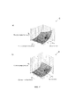
фиг. 3 изображает два поля характеристических кривых с выходными величинами «потери обмолота» и входными величинами а) «высота слоя» и «число оборотов барабана» и b) «высота слоя» и «просвет подбарабанья»,FIG. 3 shows two fields of characteristic curves with output values of “threshing loss” and input values a) “layer height” and “drum speed” and b) “layer height” and “concave clearance”,
фиг. 4 изображает два поля характеристических кривых с выходными величинами «потери сепарирования» и входными величинами а) «высота слоя» и «число оборотов барабана» и о) «высота слоя» и «просвет подбарабанья»,FIG. 4 depicts two fields of characteristic curves with output values of “separation loss” and input values a) “layer height” and “drum speed” and o) “layer height” and “concave clearance”,
фиг. 5 изображает два поля характеристических кривых с выходными величинами «привод молотильного аппарата с проскальзыванием» и входными величинами а) «высота слоя» и «число оборотов барабана» и b) «высота слоя» и «просвет подбарабанья»,FIG. 5 depicts two fields of characteristic curves with output values “threshing machine drive with slipping” and input values a) “layer height” and “drum speed” and b) “layer height” and “concave clearance”,
фиг. 6 изображает два поля характеристических кривых с выходными величинами «доля битого зерна» и входными величинами а) «высота слоя» и «число оборотов барабана» и о) «высота слоя» и «просвет подбарабанья»,FIG. 6 depicts two fields of characteristic curves with output values “fraction of broken grain” and input values a) “layer height” and “drum speed” and o) “layer height” and “concave clearance”,
фиг. 7 изображает два поля характеристических кривых с выходными величинами «потери очистки» и входными величинами а) «высота слоя» «число оборотов барабана» и b) «высота слоя» и «просвет подбарабанья».FIG. 7 depicts two fields of characteristic curves with output values “loss of cleaning” and input values a) “layer height”, “number of drum revolutions”, and b) “layer height” and “concave clearance”.
Осуществление изобретенияThe implementation of the invention
Предлагаемый зерноуборочный комбайн содержит молотильный аппарат 1 для обмолота принимаемой убранной массы и получения зерновой массы. При этом под убранной массой следует понимать весь собранный с поля и подаваемый к молотильному аппарату 1 материал, а зерновой массой обозначается зерно, полученное зерноуборочным комбайном из убранной массы. Как видно из фиг. 1, полевая растительность скашивается жатвенным аппаратом 2 комбайна, а принятая убранная масса подается наклонным питателем 3 к молотильному аппарату 1.The proposed combine harvester contains a threshing
Молотильный аппарат 1 оснащен молотильным барабаном 4, который взаимодействует с подбарабаньем 5. По ходу процесса за молотильным аппаратом 1 установлено сепарирующее устройство 6. Таким образом, подаваемый к молотильному аппарату 1 поток убранной массы далее, - без извлеченной из него зерновой массы, - подается к сепарирующему устройству 6.The threshing
В принципе молотильный аппарат 1 служит для извлечения трением преимущественной части зерновой массы из соломы убранной массы в ходе процесса обмолота. После этого в сепарирующем устройстве 6 убранная масса с еще оставшимся в ней зерном перемещается, например, встряхивается таким образом, что оставшаяся зерновая масса выделяется из соломы и остальной убранной массы. Затем зерновая масса, полученная в молотильном аппарате 1 и в сепарирующем устройстве 6, подается к очистному устройству 7. В очистном устройстве 7, которое обычно бывает многоступенчатым, от зерновой массы отделяются подаваемые вместе с ней фракции, например, полова и соломенная труха, а также необмолоченный материал, такой как верхушки колосьев или ости зерен. В заключение очищенная зерновая масса поступает по транспортирующему устройству 9, например, зерновому элеватору, в зерновой бункер 9а. Вымолоченная солома, - то есть убранная масса, оставшаяся в сепарирующем устройстве 6, - выгружается из комбайна, например, в виде валка вдоль колеи движения.In principle, the threshing
Молотильный аппарат 1 может управляться посредством задания различных машинных параметров. В зависимости от конструкции молотильного аппарата 1 к ним относятся эксплуатационные параметры, такие как число 1а оборотов барабана или другие числовые характеристики движения молотильного барабана 4, а также просвет 1b подбарабанья, то есть расстояние между молотильным барабаном 4 и подбарабаньем 5. Если молотильный аппарат 1 содержит шасталки для очистки зерна от остей, они могут также быть представлены в параметрах настройки молотильного аппарата 1.The threshing
Далее, предлагаемый зерноуборочный комбайн содержит систему 10 содействия водителю для настройки молотильного аппарата 1. Система 10 содействия водителю содержит память 11 для записи данных, - то есть память в информационном отношении, - и процессор 12 для обработки записанных в памяти 11 данных. В принципе система 10 содействия водителю выполнена таким образом, чтобы оказывать содействие водителю 13 при управлении зерноуборочным комбайном. Система 10 содействия водителю с памятью 11 и процессором 12 схематично показана на фиг. 2.Further, the proposed combine harvester includes a
В соответствии с изобретением предусмотрена система 15 датчиков для восприятия по меньшей мере части текущего состояния процесса уборки, оснащенная несколькими датчиками 16. Примеры различных датчиков 16 будут описаны ниже.In accordance with the invention, a
В соответствии с изобретением для системы 15 датчиков предназначена конфигурация 11с датчиков, которая определена видом и количеством готовых к работе датчиков 16 системы 15 и записана в памяти 11 или может быть записана в ней.In accordance with the invention, a
В памяти 11 записана функциональная системная модель 11b по меньшей мере для одной части зерноуборочного комбайна, при этом процессор 12 выполнен с возможностью самостоятельного определения по меньшей мере одного параметра 1а, 1b молотильного аппарата на основе системной модели 11b и состояния процесса уборки. Функциональной системной моделью 11b является вычислительная модель для отображения функциональных взаимосвязей внутри комбайна. Примеры таких функциональных взаимосвязей будут описаны ниже.A
В соответствии с изобретением процессор 12 определяет лежащую в основе настройки молотильного аппарата 1 системную модель 11b в зависимости от записанной в памяти 11 конфигурации 11с датчиков. Это будет пояснено дальше на примерах осуществления.In accordance with the invention, the
Предпочтительно молотильный аппарат 1 совместно с системной моделью образует молотильный автомат 14. Согласно изобретению это осуществлено посредством того, что в памяти 11 записаны множество выбираемых стратегий 11а процесса уборки, а процессор 12 выполнен с возможностью того, чтобы для реализации выбранной стратегии или стратегий 11а процесса уборки самостоятельно определять по меньшей мере один машинный параметр для молотильного аппарата 1 и задавать его для молотильного аппарата 1. Машинные параметры для молотильного аппарата 1 будут здесь называться «параметрами молотильного аппарата». Таким путем создается молотильный автомат 14, который координировано регулирует все величины, существенные для работы молотильного аппарата 1. При этом, в частности, устраняется посторонняя конкурирующая настройка, действующая противоположным образом. В отличие от этого настройка всех существенных параметров осуществляется «от одной руки». Водитель 13 может также задавать желаемый результат качества, и ему не требуется экспертных знаний для ввода требуемых подробностей для достижения этого результата.Preferably, the threshing
При определении параметров молотильного аппарата речь идет о самостоятельном определении, так как в принципе стратегия 11а процесса уборки реализуется процессором 12 без необходимости вмешательства водителя 13 или направления ему запроса при определении параметров 1а, 1b в более узком смысле. Такое вмешательство водителя 13 в принципе возможно, но не необходимо. При этом записанные стратегии 11а процесса уборки отличаются заданием цели или оптимизацией параметров процесса уборки, как это будет описано дальше.When determining the parameters of the threshing apparatus, this is an independent determination, since, in principle, the
Следует отметить, что в принципе система 10 содействия водителю может быть выполнена централизованной. При этом она служит для настройки не только молотильного аппарата 1, но также расположенных перед ним и за ним рабочих органов, таких как жатвенный аппарат 2, наклонный питатель 3, сепарирующее устройство 6, очистное устройство 7 и разбрасыватель 8. В принципе возможна также децентрализованная структура системы 10 содействия водителю, состоящая из ряда отдельных систем управления. В этом случае может быть, например, предусмотрено, что по меньшей мере часть рабочих органов комбайна снабжена относящейся к ним децентрализованной системой управления.It should be noted that, in principle, the
Предпочтительно в ходе процесса уборки системная модель 11b настраивается процессором 12 на действительное состояние процесса уборки. Это означает, что процессор 12 проверяет, соответствуют ли отраженные в системной модели 11b функциональные взаимосвязи действительному состоянию процесса уборки. При этой проверке при выявлении отклонений процессор 12 предпринимает соответствующее изменение системной модели 11b. В особенно предпочтительном примере осуществления эта настройка выполняется циклически, причем для широкого понимания термина «циклически» следует обратиться в общему тексту описания.Preferably, during the cleaning process, the
Для быстрого реагирования комбайна на изменяющиеся состояния процесса уборки предпочтительно предусмотрено, что процессор 12 определяет параметры молотильного аппарата циклически в указанном смысле. В этом отношении также следует понимать термин «циклически» в широком смысле.For the quick response of the combine to the changing conditions of the harvesting process, it is preferably provided that the
Как было указано выше, понятие «состояние процесса уборки» охватывает все данные, относящиеся к процессу уборки. К нему относятся данные полевой растительности, такие как «густота растительности», «возможность обмолота растительности» и «влажность растительности». Далее, к нему относится параметр процесса уборки «потери обмолота» как величина не обмолоченного, выложенного на поле зерна; параметр процесса уборки «доля битого зерна» как величина уложенного в зерновой бункер дробленого зерна; параметр процесса уборки «высота слоя» как величина расхода; параметр процесса уборки «потери сепарирования» как величина зерна, выложенного на поле от сепарирующего устройства 6; параметр процесса уборки «потери очистки» как величина зерна, выложенного на поле от очистного устройства 7; параметр процесса уборки «проскальзывание привода молотильного аппарата» как величина нагрузки молотильного аппарата и параметр процесса уборки «потребление топлива» как величина энергопотребления привода молотильного аппарата. И наконец, к нему относятся параметры молотильного аппарата, такие как «число оборотов барабана» и «просвет подбарабанья», а также данные окружающей среды, такие как «температура окружающей среды» и «влажность окружающей среды». Все эти относящиеся к состоянию процесса уборки данные могут определяться различным образом.As mentioned above, the concept of “state of the cleaning process” covers all data related to the cleaning process. This includes field vegetation data, such as “vegetation density”, “the possibility of threshing vegetation” and “vegetation humidity”. Further, it refers to the parameter of the harvesting process “threshing loss” as the value of not threshed, laid out on the grain field; harvesting parameter “beaten grain fraction” as the amount of crushed grain placed in the grain bin; parameter of the cleaning process "layer height" as a flow rate; the parameter of the harvesting process "loss of separation" as the amount of grain laid out on the field from the
В отношении термина «высота слоя» следует отметить, что он имеет широкое значение и охватывает как в более узком смысле высоту слоя потока убранной массы, принимаемого молотильным аппаратом, так и расход потока убранной массы, проходящего через молотильный аппарат 1. Таким образом, все выражения относятся как к высоте слоя, так и к расходу. В частности, термин «высота слоя» может быть заменен на термин «расход».Regarding the term “layer height”, it should be noted that it has a wide meaning and covers both in a narrower sense the height of the layer of the mass flow taken by the threshing machine and the flow rate of the harvested mass passing through the threshing
В зависимости от оснащения зерноуборочного комбайна система 15 датчиков может содержать различные датчики 16. В зависимости от конфигурации 11с датчиков может определяться один или несколько параметров процесса уборки. Так, параметр «потери обмолота» может определяться датчиком 16а потерь обмолота, параметр «доля битого зерна» - датчиком 16d битого зерна, параметр «высота слоя» - датчиком 16f высоты слоя, параметр «потери сепарирования» - датчиком 16b потерь сепарирования, параметр «потери очистки» - датчиком 16е потерь очистки, параметр «проскальзывание привода молотильного аппарата» - датчиком 16с проскальзывания и параметр «потребление топлива» - не показанным датчиком потребления топлива.Depending on the equipment of the combine harvester, the
Альтернативно или дополнительно, как это также показано на фиг. 1, система 15 датчиков может содержать датчик 16g валка для восприятия данных валка. При соответствующем выполнении датчик 16g валка может использоваться для восприятия доли зерна в валке 18.Alternatively or additionally, as also shown in FIG. 1, the
Описываемые здесь выбираемые водителем 13 стратегии 11а процесса уборки направлены на задание различных целей. В первом варианте по меньшей мере одна стратегия 11а процесса уборки направлена на задание цели настройки или оптимизации по меньшей мере одного параметра процесса уборки, такого как «потери обмолота», «доля битого зерна», «потери сепарирования», «потери очистки», «проскальзывание привода молотильного аппарата», «потребление топлива», или другого параметра. При этом реализация стратегий 11а должна осуществляться посредством соответствующего задания параметров молотильного аппарата, здесь и предпочтительно посредством управления главными параметрами молотильного аппарата 1 «число оборотов барабана» и «просвет подбарабанья».Described here are selected by the
Для отображения функциональных взаимосвязей из параметров процесса уборки определяется группа параметров, для которых предназначено по меньшей мере одно записанное в памяти 11 поле A-J характеристических кривых системной модели 11b, отображающее функциональные взаимосвязи в комбайне, причем данный параметр процесса уборки является выходной величиной соответствующего относящегося к нему по меньшей мере одного поля A-J характеристических кривых.To display the functional relationships from the parameters of the cleaning process, a group of parameters is determined for which at least one field AJ of characteristic curves recorded in the
В особенно предпочтительном примере осуществления, показанном на фиг. 3-7, в качестве входных величин для по меньшей мере одного поля A-J характеристических кривых определены параметр процесса уборки «высота слоя» и параметр молотильного аппарата «число оборотов барабана» или параметр молотильного аппарата «просвет подбарабанья».In a particularly preferred embodiment shown in FIG. 3-7, the cleaning process parameter “layer height” and the threshing machine parameter “drum speed” or the threshing machine parameter “concave clearance” are defined as input values for at least one field A-J of the characteristic curves.
Для отображения функциональных взаимосвязей между параметром процесса уборки в качестве выходной величины и различными входными величинами для этого параметра процесса уборки предназначены первое поле характеристических кривых и второе поле характеристических кривых. При этом для первого поля А, С, Е, G, I характеристических кривых дополнительный параметр процесса уборки «высота слоя» и параметр молотильного аппарата «число оборотов барабана» образуют входные величины (фиг. 3а)-7а)), а для второго поля (В, D, F, Н, J) дополнительный параметр процесса уборки «высота слоя» и параметр молотильного аппарата «просвет подбарабанья» образуют входные величины (фиг. 3b)-7b)).The first field of characteristic curves and the second field of characteristic curves are intended to display the functional relationships between the cleaning process parameter as an output quantity and various input values for this cleaning process parameter. Moreover, for the first field A, C, E, G, I characteristic curves, an additional parameter of the cleaning process “layer height” and the parameter of the threshing apparatus “number of drum revolutions” form input values (Fig. 3a) -7a)), and for the second field (B, D, F, H, J) an additional parameter of the cleaning process “layer height” and the parameter of the threshing device “concave clearance” form input values (Fig. 3b) -7b)).
На фиг. 3а) показано поле А характеристических кривых для функциональной взаимосвязи между выходной величиной «потери обмолота» и входными величинами «высота слоя» и «число оборотов барабана». Из него следует, что обмолот тем лучше, чем выше представляющая расход величина высоты слоя и чем выше число оборотов молотильного барабана.In FIG. 3a) shows the field A of the characteristic curves for the functional relationship between the output value of "threshing loss" and the input values of "layer height" and "drum speed". It follows that the threshing is better, the higher the layer height representing the flow rate and the higher the number of revolutions of the threshing drum.
На фиг. 3b) показано поле В характеристических кривых для функциональной взаимосвязи между выходной величиной «потери обмолота» и входными величинами «высота слоя» и «просвет подбарабанья». Из него следует, что обмолот тем лучше, чем выше представляющая расход входная величина высоты слоя и чем меньше просвет подбарабанья.In FIG. 3b) the field B is shown in the characteristic curves for the functional relationship between the output value of "threshing loss" and the input values of "layer height" and "concave clearance". It follows that the threshing is better, the higher the input value of the layer height representing the flow rate and the smaller the concave clearance.
На фиг. 4а) показано поле С характеристических кривых для функциональной взаимосвязи между выходной величиной «потери сепарирования» и входными величинами «высота слоя» и «число оборотов барабана». Из него следует, что при увеличении высоты слоя и снижении числа оборотов молотильного барабана потери сепарирования увеличиваются, то есть сепарирование ухудшается.In FIG. 4a) shows the field C of the characteristic curves for the functional relationship between the output value of "loss of separation" and the input values of "layer height" and "number of revolutions of the drum". It follows that with an increase in the layer height and a decrease in the number of revolutions of the threshing drum, separation losses increase, that is, separation is worsened.
На фиг. 4b) показано поле D характеристических кривых для функциональной взаимосвязи между выходной величиной «потери сепарирования» и входными величинами «высота слоя» и «просвет подбарабанья». Из него следует, что при увеличении представляющей расход высоты слоя и увеличении просвета подбарабанья потери сепарирования увеличиваются.In FIG. 4b) shows the field D of the characteristic curves for the functional relationship between the output value of "loss of separation" and the input values of "layer height" and "concave clearance". It follows that with an increase in the layer height representing the flow rate and an increase in the concave clearance, separation losses increase.
На фиг. 5а) показано поле Е характеристических кривых для функциональной взаимосвязи между представляющей нагрузку молотильного аппарата выходной величиной «проскальзывание привода молотильного аппарата» и входными величинами «высота слоя» и «число оборотов барабана». Из него следует, что при увеличении представляющей расход высоты слоя и снижении числа оборотов барабана нагрузка молотильного аппарата, здесь проскальзывание приводной трансмиссии молотильного аппарата, возрастает.In FIG. 5a) shows the field E of the characteristic curves for the functional relationship between the threshing machine drive output representing the threshing machine load and the input values “layer height” and “drum speed”. It follows that with an increase in the layer height representing the flow rate and a decrease in the number of drum revolutions, the load of the threshing apparatus, here the slipping of the drive transmission of the threshing apparatus, increases.
На фиг. 5b) показано поле F характеристических кривых для функциональной взаимосвязи между выходной величиной «проскальзывание привода молотильного аппарата» и входными величинами «высота слоя» и «просвет подбарабанья». Из него следует, что при увеличении высоты слоя и уменьшении просвета подбарабанья проскальзывание привода молотильного аппарата, возрастает.In FIG. 5b) shows the field F of the characteristic curves for the functional relationship between the output value “slipping of the drive of the threshing apparatus” and the input values “layer height” and “concave clearance”. It follows that with an increase in the layer height and a decrease in the concave clearance, the slippage of the drive of the threshing apparatus increases.
На фиг. 6а) показано поле G характеристических кривых для функциональной взаимосвязи между выходной величиной «доля битого зерна» и входными величинами «высота слоя» и «число оборотов барабана». Из него следует, что при увеличении числа 1а оборотов барабана и снижении высоты слоя доля битого зерна возрастает.In FIG. 6a) shows the field G of the characteristic curves for the functional relationship between the output value "fraction of broken grain" and the input values "layer height" and "number of revolutions of the drum". It follows from this that with an increase in the number of 1a revolutions of the drum and a decrease in the height of the layer, the fraction of broken grain increases.
На фиг. 6b) показано поле Н характеристических кривых для функциональной взаимосвязи между выходной величиной «доля битого зерна» и входными величинами «высота слоя» и «просвет подбарабанья». Из него следует, что при снижении представляющей расход высоты слоя и уменьшении просвета подбарабанья доля битого зерна возрастает.In FIG. 6b) shows the field H of the characteristic curves for the functional relationship between the output value "fraction of broken grain" and the input values "layer height" and "concave clearance". It follows that with a decrease in the layer height representing the flow rate and a decrease in the concave clearance, the proportion of broken grain increases.
На фиг. 7а) показано поле I характеристических кривых для функциональной взаимосвязи между выходной величиной «потери очистки» и входными величинами «высота слоя» и «число оборотов барабана». Из него следует, что при увеличении числа 1а оборотов барабана и увеличении представляющей расход высоты слоя потери очистки возрастают.In FIG. 7a) shows the field I of the characteristic curves for the functional relationship between the output value of "loss of cleaning" and the input values of "layer height" and "number of revolutions of the drum". It follows that with an increase in the
На фиг. 7b) показано поле J характеристических кривых для функциональной взаимосвязи между выходной величиной «потери очистки» и входными величинами «высота слоя» и «просвет подбарабанья». Из него следует, что при уменьшении просвета 1 b подбарабанья и увеличении представляющей расход высоты слоя потери очистки возрастают.In FIG. 7b) shows the field J of the characteristic curves for the functional relationship between the output value of "loss of cleaning" and the input values of "layer height" and "concave clearance". It follows from this that with a decrease in the
Указанная выше настройка системной модели 11b на действительное состояние процесса уборки для случая системной модели 11b по меньшей мере с одним полем А-J характеристических кривых предпочтительно осуществляется посредством того, что процессор 12 в ходе работы на уборке циклически настраивает по меньшей мере одно поле A-J характеристических кривых на процесс уборки. При этом определение системной модели 11b процессором 12 в зависимости от записанной в памяти 11 конфигурации 11с датчиков охватывает помимо определения полей A-J характеристических кривых также определение настройки системной модели 11b.The above adjustment of the
На фиг. 3-7 в диаграммы внесен ряд реальных измеренных датчиками величин для соответствующего состояния процесса уборки. При указанной настройке процессор 12 предпринимает изменение конкретного поля A-J характеристических кривых для его приближения к реальным измеренным датчиками величинам. При этом, например, все поле A-J характеристических кривых может быть смещено в направлении к текущей выходной величине, вверх или вниз на фиг. 3-7. Однако наиболее предпочтительно, когда приближение поля A-J характеристических кривых влечет за собой также изменение хода характеристических кривых.In FIG. 3-7, a number of real measured by sensors values for the corresponding state of the cleaning process are entered in the diagrams. With this setting, the
В рамках указанного определения системной модели 11b процессор 12 подчиняет поля A-J характеристических кривых текущей настройке различных характеристик.Within the specified definition of
В первом варианте предусмотрено, что процессор 12 определяет по меньшей мере одно из полей A-J характеристических кривых как динамическое поле характеристических кривых и в ходе процесса уборки, в частности, циклически, настраивает его на воспринятое датчиками состояние процесса уборки.In the first embodiment, it is provided that the
Во втором варианте предусмотрено, что процессор 12 для по меньшей мере одного параметра процесса уборки группы параметров определяет поле A-J характеристических кривых как статическое поле и не подвергает его настройке на воспринятое датчиками состояние процесса уборки. Предпочтительно это относится к тому случаю, когда данный параметр процесса уборки согласно конфигурации 11с датчиков не определяется системой 15 датчиков, то есть соответствующий датчик 16 отсутствует или не готов к работе.In the second embodiment, it is provided that the
Далее, предпочтительно процессор 12 для по меньшей мере одного параметра процесса уборки группы параметров, в частности, в зависимости от конфигурации 11с датчиков, допускает ввод со стороны пользователя к параметру процесса уборки или ввод параметра процесса уборки через устройство 19 ввода/вывода. Предпочтительно в этом случае процессор 12 настраивает соответствующее поле A-J характеристических кривых на основе ввода со стороны пользователя. Однако альтернативно или дополнительно может быть предусмотрено, что предпринимается самостоятельное определение по меньшей мере одного параметра 1а, 1b молотильного аппарата на основе ввода со стороны пользователя. При этом предпочтительно процессор 12 создает запрос относительно данного параметра процесса уборки и выводит его на устройство 19 ввода/вывода. В ответ на этот запрос водитель 13 может ввести через устройство 19 ввода/вывода по меньшей мере часть состояния процесса уборки. Для этого устройство 19 ввода/вывода содержит соответствующие элементы 20а ввода и элементы 20b вывода.Further, preferably, the
Для обеспечения возможности реагирования на изменение конфигурации 15 датчиков в ходе работы процессор 12 проверяет, в частности, циклически, работоспособны ли все датчики 16 в соответствии с записанной в памяти 11 конфигурацией 11с датчиков. В том случае, когда один датчик 16 или несколько датчиков 16 неработоспособны, процессор 12 предпринимает модификацию конфигурации 11с датчиков и записывает ее в память 11. Благодаря этому при дальнейшей работе может учитываться новая конфигурация 11с датчиков, как это было описано выше.In order to be able to respond to a change in the configuration of the
Указанное определение системной модели 11b будет продемонстрировано на следующих трех примерах.The specified definition of
Для первого случая эксплуатации, в котором конфигурация 11с датчиков содержит готовые к работе датчик 16b потерь сепарирования и датчик 16е потерь очистки, но не готовые к работе датчик 16d битого зерна и датчик 16а потерь обмолота, процессор 12 определяет относящиеся к параметрам процесса уборки «битое зерно» и «обмолот» поля G, Н, А, В характеристических кривых (фиг. 6, 3) предпочтительно как статические поля характеристических кривых, а относящиеся к параметрам «потери сепарирования» и «потери очистки» поля С, D, I, J (фиг. 4, 7) как динамические поля характеристических кривых.For the first operating case, in which the
Для второго случая эксплуатации, в котором конфигурация 11с датчиков содержит готовые к работе датчик 16b потерь сепарирования, датчик 16е потерь очистки и датчик 16d битого зерна, но не готовый к работе датчик 16а потерь обмолота, процессор 12 определяет относящееся к параметрам процесса уборки «потери сепарирования» поле А, В характеристических кривых (фиг. 3) как статическое поле характеристических кривых, а относящиеся к параметрам процесса уборки «потери обмолота», «потери очистки» и «потери битого зерна» поля С, D, I, J, G, Н характеристических кривых (фиг. 4, 7, 6) как динамические поля характеристических кривых.For the second operating case, in which the
Для третьего случая эксплуатации, в котором конфигурация 11с датчиков содержит готовые к работе датчик 16b потерь сепарирования, датчик 16е потерь очистки, датчик 16d битого зерна и датчик 16а потерь обмолота, процессор 12 определяет относящееся к параметрам процесса уборки «потери сепарирования», «потери очистки», «потери битого зерна» и «потери обмолота» поля С, D, I, J, G, Н, А, В характеристических кривых (фиг. 4, 7, 6, 3) как динамические поля характеристических кривых.For the third operating case, in which the
Перечень позицийList of items
Claims (16)
Applications Claiming Priority (2)
| Application Number | Priority Date | Filing Date | Title |
|---|---|---|---|
| DE102015004343.9 | 2015-04-02 | ||
| DE102015004343.9A DE102015004343A1 (en) | 2015-04-02 | 2015-04-02 | Harvester |
Publications (3)
| Publication Number | Publication Date |
|---|---|
| RU2016110485A RU2016110485A (en) | 2017-09-28 |
| RU2016110485A3 RU2016110485A3 (en) | 2019-05-29 |
| RU2708842C2 true RU2708842C2 (en) | 2019-12-11 |
Family
ID=55182266
Family Applications (1)
| Application Number | Title | Priority Date | Filing Date |
|---|---|---|---|
| RU2016110485A RU2708842C2 (en) | 2015-04-02 | 2016-03-23 | Combine-sorter |
Country Status (6)
| Country | Link |
|---|---|
| US (1) | US10231380B2 (en) |
| EP (1) | EP3075223B1 (en) |
| CA (1) | CA2921731A1 (en) |
| DE (1) | DE102015004343A1 (en) |
| PL (1) | PL3075223T3 (en) |
| RU (1) | RU2708842C2 (en) |
Families Citing this family (40)
| Publication number | Priority date | Publication date | Assignee | Title |
|---|---|---|---|---|
| US20180271015A1 (en) * | 2017-03-21 | 2018-09-27 | Blue River Technology Inc. | Combine Harvester Including Machine Feedback Control |
| US11140807B2 (en) * | 2017-09-07 | 2021-10-12 | Deere & Company | System for optimizing agricultural machine settings |
| DE102018104286A1 (en) * | 2018-02-26 | 2019-08-29 | Claas Selbstfahrende Erntemaschinen Gmbh | Self-propelled forage harvester |
| DE102018108405A1 (en) * | 2018-04-10 | 2019-10-10 | Claas Selbstfahrende Erntemaschinen Gmbh | Combine harvester and method for its control |
| US11589509B2 (en) | 2018-10-26 | 2023-02-28 | Deere & Company | Predictive machine characteristic map generation and control system |
| US11467605B2 (en) | 2019-04-10 | 2022-10-11 | Deere & Company | Zonal machine control |
| US11240961B2 (en) | 2018-10-26 | 2022-02-08 | Deere & Company | Controlling a harvesting machine based on a geo-spatial representation indicating where the harvesting machine is likely to reach capacity |
| US11653588B2 (en) | 2018-10-26 | 2023-05-23 | Deere & Company | Yield map generation and control system |
| US11957072B2 (en) | 2020-02-06 | 2024-04-16 | Deere & Company | Pre-emergence weed detection and mitigation system |
| US11178818B2 (en) | 2018-10-26 | 2021-11-23 | Deere & Company | Harvesting machine control system with fill level processing based on yield data |
| US11672203B2 (en) | 2018-10-26 | 2023-06-13 | Deere & Company | Predictive map generation and control |
| US11641800B2 (en) | 2020-02-06 | 2023-05-09 | Deere & Company | Agricultural harvesting machine with pre-emergence weed detection and mitigation system |
| US11079725B2 (en) | 2019-04-10 | 2021-08-03 | Deere & Company | Machine control using real-time model |
| US11234366B2 (en) | 2019-04-10 | 2022-02-01 | Deere & Company | Image selection for machine control |
| US11778945B2 (en) | 2019-04-10 | 2023-10-10 | Deere & Company | Machine control using real-time model |
| DE102019119126A1 (en) * | 2019-07-15 | 2021-01-21 | Claas Selbstfahrende Erntemaschinen Gmbh | Agricultural harvester |
| US11477940B2 (en) | 2020-03-26 | 2022-10-25 | Deere & Company | Mobile work machine control based on zone parameter modification |
| US11635765B2 (en) | 2020-10-09 | 2023-04-25 | Deere & Company | Crop state map generation and control system |
| US11825768B2 (en) | 2020-10-09 | 2023-11-28 | Deere & Company | Machine control using a predictive map |
| US11946747B2 (en) | 2020-10-09 | 2024-04-02 | Deere & Company | Crop constituent map generation and control system |
| US11845449B2 (en) | 2020-10-09 | 2023-12-19 | Deere & Company | Map generation and control system |
| US11895948B2 (en) | 2020-10-09 | 2024-02-13 | Deere & Company | Predictive map generation and control based on soil properties |
| US11874669B2 (en) | 2020-10-09 | 2024-01-16 | Deere & Company | Map generation and control system |
| US11871697B2 (en) | 2020-10-09 | 2024-01-16 | Deere & Company | Crop moisture map generation and control system |
| US11675354B2 (en) | 2020-10-09 | 2023-06-13 | Deere & Company | Machine control using a predictive map |
| US11849671B2 (en) | 2020-10-09 | 2023-12-26 | Deere & Company | Crop state map generation and control system |
| US11711995B2 (en) | 2020-10-09 | 2023-08-01 | Deere & Company | Machine control using a predictive map |
| US11849672B2 (en) | 2020-10-09 | 2023-12-26 | Deere & Company | Machine control using a predictive map |
| US11727680B2 (en) | 2020-10-09 | 2023-08-15 | Deere & Company | Predictive map generation based on seeding characteristics and control |
| US11927459B2 (en) | 2020-10-09 | 2024-03-12 | Deere & Company | Machine control using a predictive map |
| US11864483B2 (en) | 2020-10-09 | 2024-01-09 | Deere & Company | Predictive map generation and control system |
| US11889788B2 (en) | 2020-10-09 | 2024-02-06 | Deere & Company | Predictive biomass map generation and control |
| US11844311B2 (en) | 2020-10-09 | 2023-12-19 | Deere & Company | Machine control using a predictive map |
| US11474523B2 (en) | 2020-10-09 | 2022-10-18 | Deere & Company | Machine control using a predictive speed map |
| US11650587B2 (en) | 2020-10-09 | 2023-05-16 | Deere & Company | Predictive power map generation and control system |
| US11592822B2 (en) | 2020-10-09 | 2023-02-28 | Deere & Company | Machine control using a predictive map |
| US11889787B2 (en) | 2020-10-09 | 2024-02-06 | Deere & Company | Predictive speed map generation and control system |
| CN112042371B (en) * | 2020-10-13 | 2021-07-20 | 中国农业大学 | Corn grain cleaning loss monitoring system and method |
| US20230034308A1 (en) * | 2021-07-28 | 2023-02-02 | Cnh Industrial America Llc | Agricultural management system and methods |
| DE102021125124A1 (en) | 2021-09-28 | 2023-03-30 | Claas Selbstfahrende Erntemaschinen Gmbh | Agricultural work machine with map control |
Citations (4)
| Publication number | Priority date | Publication date | Assignee | Title |
|---|---|---|---|---|
| SU1720545A1 (en) * | 1986-10-08 | 1992-03-23 | Головное специализированное конструкторское бюро по комплексам зерноуборочных машин Производственного объединения "Ростсельмаш" | Method for automatic process control of grain combine harvester |
| EP2728523A1 (en) * | 2012-11-05 | 2014-05-07 | CLAAS Selbstfahrende Erntemaschinen GmbH | Assistance system for optimising vehicle operation |
| RU2533922C2 (en) * | 2009-02-20 | 2014-11-27 | КЛААС Зельбстфаренде Эрнтемашинен ГмбХ | System "driver assistant" of agricultural working machine |
| EP2837279A2 (en) * | 2013-08-12 | 2015-02-18 | Deere & Company | Driver assistance system |
Family Cites Families (8)
| Publication number | Priority date | Publication date | Assignee | Title |
|---|---|---|---|---|
| US4296409A (en) * | 1979-03-12 | 1981-10-20 | Dickey-John Corporation | Combine performance monitor |
| US6553300B2 (en) * | 2001-07-16 | 2003-04-22 | Deere & Company | Harvester with intelligent hybrid control system |
| DE10360597A1 (en) * | 2003-12-19 | 2005-07-28 | Claas Selbstfahrende Erntemaschinen Gmbh | Method and device for controlling working elements of a combine harvester |
| DE102005026159A1 (en) | 2005-06-06 | 2007-01-25 | Claas Selbstfahrende Erntemaschinen Gmbh | Method for controlling a harvesting machine |
| DE102006044628A1 (en) * | 2006-09-19 | 2008-04-03 | Claas Selbstfahrende Erntemaschinen Gmbh | Method for controlling a display device in a harvester |
| DE102010017687A1 (en) * | 2010-07-01 | 2012-01-05 | Claas Selbstfahrende Erntemaschinen Gmbh | Method for adjusting at least one working member of a self-propelled harvester |
| DE102013106133A1 (en) * | 2012-07-16 | 2014-06-12 | Claas Selbstfahrende Erntemaschinen Gmbh | Self-propelled agricultural machine |
| DE102013201996A1 (en) * | 2013-02-07 | 2014-08-07 | Deere & Company | Method for setting operating parameters of a harvester |
-
2015
- 2015-04-02 DE DE102015004343.9A patent/DE102015004343A1/en not_active Withdrawn
-
2016
- 2016-01-20 EP EP16152060.6A patent/EP3075223B1/en active Active
- 2016-01-20 PL PL16152060T patent/PL3075223T3/en unknown
- 2016-02-25 CA CA2921731A patent/CA2921731A1/en active Pending
- 2016-03-23 RU RU2016110485A patent/RU2708842C2/en active
- 2016-03-30 US US15/084,686 patent/US10231380B2/en active Active
Patent Citations (4)
| Publication number | Priority date | Publication date | Assignee | Title |
|---|---|---|---|---|
| SU1720545A1 (en) * | 1986-10-08 | 1992-03-23 | Головное специализированное конструкторское бюро по комплексам зерноуборочных машин Производственного объединения "Ростсельмаш" | Method for automatic process control of grain combine harvester |
| RU2533922C2 (en) * | 2009-02-20 | 2014-11-27 | КЛААС Зельбстфаренде Эрнтемашинен ГмбХ | System "driver assistant" of agricultural working machine |
| EP2728523A1 (en) * | 2012-11-05 | 2014-05-07 | CLAAS Selbstfahrende Erntemaschinen GmbH | Assistance system for optimising vehicle operation |
| EP2837279A2 (en) * | 2013-08-12 | 2015-02-18 | Deere & Company | Driver assistance system |
Also Published As
| Publication number | Publication date |
|---|---|
| RU2016110485A (en) | 2017-09-28 |
| RU2016110485A3 (en) | 2019-05-29 |
| US10231380B2 (en) | 2019-03-19 |
| CA2921731A1 (en) | 2016-10-02 |
| PL3075223T3 (en) | 2020-06-29 |
| US20160286721A1 (en) | 2016-10-06 |
| EP3075223A1 (en) | 2016-10-05 |
| EP3075223B1 (en) | 2019-12-04 |
| DE102015004343A1 (en) | 2016-10-06 |
Similar Documents
| Publication | Publication Date | Title |
|---|---|---|
| RU2708842C2 (en) | Combine-sorter | |
| RU2708025C2 (en) | Combine harvester | |
| RU2711340C2 (en) | Self-cleaning sweeper | |
| US10448569B2 (en) | Method and apparatus for operating a combine harvester | |
| US11812683B2 (en) | Method for operating a harvesting machine with the aid of a plant growth model | |
| US9901031B2 (en) | Automatic tuning of an intelligent combine | |
| EP2837279B1 (en) | Driver assistance system | |
| CN105875030B (en) | Multi-sensor crop yield determination | |
| EP3000305B1 (en) | Yield estimation | |
| US10034423B2 (en) | Biomass sensing | |
| US20180164471A1 (en) | Yield estimation | |
| US9332693B1 (en) | Agricultural combine harvester with harvesting and winnowing optimization control system | |
| Hanna et al. | Grain harvesting machinery | |
| US20210015045A1 (en) | Federated harvester control | |
| US11375662B2 (en) | Apparatus and method for monitoring grain content within a tailings system of an agricultural harvester | |
| Hanna et al. | Grain harvesting machinery design | |
| JP7433145B2 (en) | harvester | |
| JP7423440B2 (en) | harvester | |
| US20210169006A1 (en) | Electronic soil coping system applied to a grain harvesting platform | |
| JP2022173858A (en) | combine |
Legal Events
| Date | Code | Title | Description |
|---|---|---|---|
| QZ41 | Official registration of changes to a registered agreement (patent) |
Free format text: LICENCE FORMERLY AGREED ON 20151224 Effective date: 20210407 |