RU2706503C1 - Pump unit for production of super-viscous oil from horizontal well - Google Patents
Pump unit for production of super-viscous oil from horizontal well Download PDFInfo
- Publication number
- RU2706503C1 RU2706503C1 RU2019103484A RU2019103484A RU2706503C1 RU 2706503 C1 RU2706503 C1 RU 2706503C1 RU 2019103484 A RU2019103484 A RU 2019103484A RU 2019103484 A RU2019103484 A RU 2019103484A RU 2706503 C1 RU2706503 C1 RU 2706503C1
- Authority
- RU
- Russia
- Prior art keywords
- shank
- horizontal
- holes
- pump
- super
- Prior art date
Links
- 238000004519 manufacturing process Methods 0.000 title abstract description 15
- 238000001914 filtration Methods 0.000 claims abstract description 10
- 238000009434 installation Methods 0.000 claims abstract description 10
- 238000004891 communication Methods 0.000 claims abstract description 6
- 238000007789 sealing Methods 0.000 claims abstract description 5
- 238000005086 pumping Methods 0.000 claims description 7
- 238000000034 method Methods 0.000 abstract description 7
- 239000003129 oil well Substances 0.000 abstract 1
- 239000000126 substance Substances 0.000 abstract 1
- 230000015572 biosynthetic process Effects 0.000 description 7
- 238000000926 separation method Methods 0.000 description 5
- 244000309464 bull Species 0.000 description 4
- 239000007788 liquid Substances 0.000 description 4
- XLYOFNOQVPJJNP-UHFFFAOYSA-N water Substances O XLYOFNOQVPJJNP-UHFFFAOYSA-N 0.000 description 4
- 238000005452 bending Methods 0.000 description 1
- 230000003247 decreasing effect Effects 0.000 description 1
- 238000010586 diagram Methods 0.000 description 1
- 238000000605 extraction Methods 0.000 description 1
- 239000011521 glass Substances 0.000 description 1
- 238000010438 heat treatment Methods 0.000 description 1
- 239000013307 optical fiber Substances 0.000 description 1
Images
Classifications
-
- E—FIXED CONSTRUCTIONS
- E21—EARTH OR ROCK DRILLING; MINING
- E21B—EARTH OR ROCK DRILLING; OBTAINING OIL, GAS, WATER, SOLUBLE OR MELTABLE MATERIALS OR A SLURRY OF MINERALS FROM WELLS
- E21B43/00—Methods or apparatus for obtaining oil, gas, water, soluble or meltable materials or a slurry of minerals from wells
- E21B43/16—Enhanced recovery methods for obtaining hydrocarbons
- E21B43/24—Enhanced recovery methods for obtaining hydrocarbons using heat, e.g. steam injection
-
- E—FIXED CONSTRUCTIONS
- E21—EARTH OR ROCK DRILLING; MINING
- E21B—EARTH OR ROCK DRILLING; OBTAINING OIL, GAS, WATER, SOLUBLE OR MELTABLE MATERIALS OR A SLURRY OF MINERALS FROM WELLS
- E21B43/00—Methods or apparatus for obtaining oil, gas, water, soluble or meltable materials or a slurry of minerals from wells
- E21B43/34—Arrangements for separating materials produced by the well
- E21B43/38—Arrangements for separating materials produced by the well in the well
Landscapes
- Life Sciences & Earth Sciences (AREA)
- Engineering & Computer Science (AREA)
- Geology (AREA)
- Mining & Mineral Resources (AREA)
- Physics & Mathematics (AREA)
- Environmental & Geological Engineering (AREA)
- Fluid Mechanics (AREA)
- General Life Sciences & Earth Sciences (AREA)
- Geochemistry & Mineralogy (AREA)
- Structures Of Non-Positive Displacement Pumps (AREA)
Abstract
Description
Изобретение относится к нефтедобывающей промышленности, в частности к способам эксплуатации горизонтальных скважин сверхвязкой нефти (СВН) при разработке тепловыми методами.The invention relates to the oil industry, in particular to methods for operating horizontal wells of extra-viscous oil (IOS) in the development of thermal methods.
Известно устройство для сепарации газа погружного электроцентробежного насоса в кожухе (патент на ПМ RU №184048, МПК Е21В 43/38, опубл. 12.10.2018 в Бюл. №29), в котором для скважин с большим газовым фактором погружной электродвигатель с гидрозащитой, охлаждаемый перекачиваемой жидкостью, снабжен наружным герметичным кожухом, который герметично соединен с входным модулем электроцентробежного насоса и выполнен с возможностью изолирования приема насоса от межтрубного пространства, причем ниже герметичного кожуха погружного электродвигателя расположен газосепаратор с возможностью передачи крутящего момента от вала погружного электродвигателя через дополнительную гидрозащиту и входной модуль на вал газосепаратора и гидравлически соединен с полостью колонны труб хвостовика, а входной модуль установлен таким образом, что дегазированная жидкость с выхода газосепаратора поступает в центральный канал входного модуля и выходит в полость герметичного кожуха погружного электродвигателя, при этом хвостовик спущен от нижней части газосепаратора вниз вплоть до интервала перфорации скважины или ниже.A device is known for gas separation of a submersible electric centrifugal pump in a casing (patent for PM RU No. 184048, IPC ЕВВ 43/38, published on October 12, 2018 in Bull. No. 29), in which, for wells with a large gas factor, a submersible motor with hydraulic protection, cooled the pumped liquid is equipped with an external sealed casing, which is hermetically connected to the input module of the electric centrifugal pump and is configured to isolate the pump intake from the annulus, and lower than the sealed casing of the submersible motor The gas separator is capable of transmitting torque from the shaft of the submersible motor through an additional hydraulic protection and the input module to the gas separator shaft and is hydraulically connected to the cavity of the liner pipe string, and the input module is installed so that the degassed liquid from the gas separator output enters the central channel of the input module and exits into the cavity of the sealed casing of the submersible electric motor, while the liner is lowered from the bottom of the gas separator down to the interval of perforation of the well Agins or lower.
Недостатком данного устройства являются невозможность работы в горизонтальных стволах скважин из-за вертикального газосепаратора и невозможность работы в скважинах, предназначенных для добычи нагретой продукции пласта, из-за отсутствия отвода газа вдоль хвостовика.The disadvantage of this device is the inability to work in horizontal wellbores due to the vertical gas separator and the inability to work in wells designed to produce heated formation products, due to the lack of gas outlet along the liner.
Известна скважинная насосная установка (патент RU №2076952, МПК F04D 47/02, опубл. 10.04.1997 в Бюл. №10), где погружная насосная установка, размещенная в наклонной или прямой скважине, содержащая колонну насосно-компрессорных труб, состоящую из соединенных последовательно между собой секций, на спускаемом конце которой крепится насосная установка, собранная из набора модульных секций; токоведущий кабель, причем модульные секции установлены с возможностью ограниченного углового перемещения относительно насосно-компрессорной трубы и друг друга с защитой от скручивания корпусов и кабеля за счет пружинных стержней, установленных параллельно продольной оси насосной установки; концы пружинных стержней зажаты в отверстиях ступицы корпуса и накидной гайки, свинчивающей стыкуемые корпуса, один из которых имеет внутреннюю расточку под сферу, наружную резьбу под гайку и присоединительный фланец под хомут, а другой наружную сферу, накидную гайку, ступицу с отверстиями под стержни и присоединительный фланец. Валы, проходящие внутри модульных секций погружной установки, соединены последовательно с возможностью самостоятельного углового перемещения, независимо от изгиба пружинных стержней. Крепление соединений с пружинными стержнями производится с помощью хомутов.A well-known pumping unit (patent RU No. 2076952, IPC F04D 47/02, publ. 04/10/1997 in Bull. No. 10), where a submersible pumping unit located in an inclined or straight well, containing a tubing string consisting of connected sequentially between each other sections, on the descent end of which a pump unit is assembled, assembled from a set of modular sections; current-carrying cable, and the modular sections are installed with the possibility of limited angular movement relative to the tubing and each other with protection against twisting of the housings and cable due to spring rods mounted parallel to the longitudinal axis of the pump unit; the ends of the spring rods are clamped in the openings of the hub of the housing and the union nut screwing the abutting housings, one of which has an internal bore for a sphere, an external thread for a nut and a connecting flange for a collar, and the other external sphere, a union nut, a hub with holes for the rods and a connecting flange. The shafts passing inside the modular sections of the submersible installation are connected in series with the possibility of independent angular movement, regardless of the bending of the spring rods. Fastening of connections with spring rods is carried out using clamps.
Недостатками указанной компоновки являются его дороговизна и добавление узлов, которые усложняют саму конструкцию, низкая надежность из-за незащищенности кабеля и невозможность работы в скважинах, предназначенных для добычи нагретой продукции пласта, из-за отсутствия отвода газа вдоль хвостовика.The disadvantages of this arrangement are its high cost and the addition of nodes that complicate the design itself, low reliability due to the insecurity of the cable and the inability to work in wells designed to produce heated formation products, due to the lack of gas outlet along the liner.
Известен также погружной насос (патент на ПМ RU №44766, 04.02.2004, МПК F04D 13/10, опубл, 27.03.2005 в Бюл. №9), содержащий приводной электродвигатель, охлаждаемый перекачиваемой жидкостью, насосный узел с приемной сеткой, при этом приводной электродвигатель с приемной сеткой снабжены дополнительным корпусом вдоль всего приводного электродвигателя и сообщение с межтрубным пространством происходит под электродвигателем, причем дополнительный корпус снабжен центратором в нижней части дополнительного корпуса.Also known is a submersible pump (patent for PM RU No. 44766, 04.02.2004, IPC F04D 13/10, publ., March 27, 2005, Bull. No. 9), comprising a drive motor cooled by the pumped liquid, a pump unit with a receiving screen, the drive motor with the receiving grid is provided with an additional housing along the entire drive motor and communication with the annular space occurs under the electric motor, and the additional housing is equipped with a centralizer in the lower part of the additional housing.
Недостатками указанного насоса являются то, что его использование предлагалось на вертикальных скважинах, а также отсутствие хвостовика для увеличения точки отбора и ряда другого оборудования для эффективной работы установки в горизонтальной части скважин, предназначенных для добычи сверхвязкой нефти (СВН). Указанная компоновка не защищает от повреждений погружного кабеля на горизонтальных участках скважин СВН, и не обеспечивает эффективную работу и подачу насосной установки.The disadvantages of this pump are that its use was proposed in vertical wells, as well as the absence of a liner to increase the selection point and a number of other equipment for the effective operation of the installation in the horizontal part of the wells intended for the production of super-viscous oil (IOS). This arrangement does not protect against damage to the submersible cable in the horizontal sections of the IOS wells, and does not provide efficient operation and supply of the pumping unit.
Наиболее близким по технической сущности является установка для внутрискважинного разделения нефти от воды (патент RU №2531976, МПК Е21В 43/38, опубл. 27.10.2014 в Бюл. №30), включающая колонну насосно-компрессорных труб с электроцентробежным насосом и промывочно-обратным клапаном, спущенным в эксплуатационную колонну скважины, межтрубное пространство над насосом для накопления и резервирования отделившейся нефти, разделительную камеру, расположенную в нижней части ствола скважины под электроцентробежным насосом, проходной канал, сообщающий межтрубное пространство над насосом с разделительной камерой, впускные отверстия для поступления добываемой воды, причем электроцентробежный насос снабжен наружным герметизирующим кожухом, выполненным с возможностью гидравлического сообщения приема электроцентробежного насоса с входным устройством, размещенным в разделительной камере, состоящим из заглушенного с нижнего конца хвостовика, поделенного на секции с впускными отверстиями, при этом на уровне каждого впускного отверстия хвостовик снабжен стаканом, выполняющим функции впуска разделившийся воды во входное устройство и гидрозатвора для нефтяных капель, причем впускные отверстия располагаются в один ряд вдоль хвостовика и выполнены с уменьшающимся диаметром в каждой последующей секции по направлению вверх, а в качестве проходного канала для нефтяных капель служит зазор между кожухом и эксплуатационной колонной скважины.The closest in technical essence is the installation for downhole separation of oil from water (patent RU No. 2531976, IPC ЕВВ 43/38, published on 10/27/2014 in Bull. No. 30), including a tubing string with an electric centrifugal pump and a flush-return a valve lowered into the production casing of the well, the annulus above the pump for accumulating and reserving the separated oil, a separation chamber located in the lower part of the well bore under the electric centrifugal pump, a passage channel communicating the intern uby space above the pump with a separation chamber, inlets for the production of produced water, and the electric centrifugal pump is equipped with an external sealing casing, made with the possibility of hydraulic communication receiving the electric centrifugal pump with an input device located in the separation chamber, consisting of a muffled from the lower end of the shaft, divided into sections with inlets, while at the level of each inlet, the shank is equipped with a glass that performs the functions of the inlet divided water into the input device and a water trap for oil droplets, the inlet openings being arranged in a row along the liner and made with a decreasing diameter in each subsequent section upward, and the gap between the casing and the production casing of the well serves as a passage channel for oil droplets.
Недостатками данной установки являются узкая область применения из-за отсутствия возможности использования в горизонтальных скважинах, так как не обеспечивает эффективную работу для добычи СВН термическими методами с защитой от механических повреждений и выделенного газа и/или пара.The disadvantages of this installation are the narrow scope due to the lack of the possibility of use in horizontal wells, since it does not provide effective work for the production of IOS by thermal methods with protection against mechanical damage and the released gas and / or steam.
Техническими задачами предполагаемого изобретения является разработка надежной конструкции насосной установки для добычи СВН из горизонтальной скважины, позволяющей работать в горизонтальных скважинах и при добыче СВН термическими методами с защитой от механических повреждений и выделенного газа и/или пара.The technical objectives of the alleged invention is the development of a reliable design of a pumping unit for the production of IOS from a horizontal well, which allows working in horizontal wells and during the production of IOS by thermal methods with protection against mechanical damage and the released gas and / or steam.
Технические задачи решаются насосной установкой для добычи сверхвязкой нефти из горизонтальной скважины, включающей электроцентробежный насос, спускаемый на колонне труб, снабженный наружным герметизирующим кожухом, выполненным с возможностью гидравлического сообщения приема электроцентробежного насоса с хвостовиком, оснащенным расположенными равномерно по периметру в один ряд отверстиями.Technical problems are solved by a pumping unit for the production of extra-viscous oil from a horizontal well, including an electric centrifugal pump, lowered on a pipe string, equipped with an external sealing casing made with the possibility of hydraulic communication for receiving an electric centrifugal pump with a shaft equipped with holes uniformly arranged along the perimeter.
Новым является то, что хвостовик собран длиной, достаточной для входа в фильтрующую часть горизонтального ствола скважины, с концом в требуемом интервале установки, конец хвостовика снабжен обтекаемой насадкой с наружным диаметром большим, чем наружный диаметр хвостовика, при этом в конце хвостовика расположены входные каналы с суммарной площадью не менее площади проходного сечения хвостовика, а исходя из перепадов температур вдоль горизонтального ствола и перепадов высот горизонтального ствола для выпуска газа и/или пара из хвостовика определяют места расположения рядов отверстий, изготавливаемых с суммарным поперечным сечением в ряду как минимум в 100 раз меньшим площади проходного сечения хвостовика, причем первый ряд отверстий расположен на расстоянии 0,5-15 м от кожуха.What is new is that the liner is assembled with a length sufficient to enter the filtering part of the horizontal wellbore, with an end in the required installation interval, the end of the liner is equipped with a streamlined nozzle with an outer diameter larger than the outer diameter of the liner, while inlet channels with the total area of not less than the passage through section of the liner, and based on temperature differences along the horizontal well and elevations of the horizontal well to release gas and / or steam from the tail and determine the locations of openings series arrangement manufactured with a total cross section in the range of at least 100 times less than the shank passage area, the first series of holes is situated at a distance of 0.5-15 m from the housing.
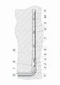
На чертеже изображена схема насосной установки в скважине.The drawing shows a diagram of a pumping unit in the well.
Насосная установка для добычи сверхвязкой нефти из горизонтальной скважины 1 включает электроцентробежный насос 2, спускаемый на колонне труб 3, снабженный наружным герметизирующим кожухом 4, выполненным с возможностью гидравлического сообщения приема электроцентробежного насоса 2 с хвостовиком 5, оснащенным расположенными равномерно по периметру в один ряд отверстиями 6. Хвостовик 5 собран длиной, достаточной для входа в фильтрующую часть 7 горизонтального ствола 8 скважины 1, с концом в требуемом интервале установки. Конец хвостовика 5 снабжен обтекаемой насадкой 9 с наружным диаметром большим, чем наружный диаметр хвостовика 5. В конце хвостовика 5 расположены входные каналы (не показаны) с суммарной площадью не менее площади проходного сечения хвостовика 5 для снижения сопротивления потоку добываемой продукции пласта 10, в котором располагается горизонтальный ствол 8 скважины 1. Исходя из перепадов температур вдоль горизонтального ствола 8 и перепадов высот (не показаны) горизонтального ствола 8 для выпуска газа и пара из хвостовика 5 определяют места расположения рядов отверстий 6, 6', 6'' … 6n, изготавливаемых с суммарным поперечным сечением в ряду как минимум в 100 раз меньшим площади проходного сечения хвостовика 5 для фильтрации через них только газа и пара (определено эмпирически). Минимальная площадь поперечных отверстий 6, 6', 6'' … 6n определяется минимальным диаметром сверла (обычно 1,5-2 мм) и одним отверстием 6, 6', 6'' … 6n в ряду, а максимальная - не менее чем 100 раз меньше площади проходного сечения хвостовика 5. При этом количество и диаметр отверстий 6, 6', 6'' … 6n в ряду может быть любой. Первый ряд отверстий 6 расположен на расстоянии 0,5-15 м от кожуха 4 (определено эмпирически) для исключения захвата газа и пара насосом 2.A pump installation for the production of super-viscous oil from a
Насосная установка работает следующим образом.The pump installation operates as follows.
Скважину 1 бурят до проектной глубины (например, до горизонтального участка 8), оснащают обсадными колоннами и цементируют (не показано), далее меньшим диаметром бурят горизонтальный участок 8 в пласте 10 меньшим диаметром, чем ствол скважины 1 с обсадной колонной. В пробуренный открытый ствол устанавливают фильтр (показан условно), образуя фильтрующую часть 7. После чего проводят геофизические исследования для определения перепадов высот горизонтального ствола 8 и его фильтрующей части 7. После прогрева пласта 1 (например, нагревателями, паром, в том числе из расположенной(ых) рядом скважин(ы) или т.п.) проводят геофизические исследования для определения распределения температуры по стволу скважины и/или в скважину 1 спускают гибкую трубу 11, оснащенную оптико-волоконным кабелем с датчиками температуры (не показаны) на всю длину горизонтального участка 8. Исходя из показаний датчиков, определяют температуру вдоль горизонтального ствола 8. Исходя из определенных перепадов температур вдоль горизонтального ствола 8 и перепадов высот горизонтального ствола 8 для выпуска газа и пара из хвостовика 5, определяют места расположения рядов отверстий 6, 6', 6'' … 6n (обычно в верхних точках в непосредственной близости от максимальных температур). Первый ряд отверстий 6 располагают на расстоянии 0,5-15 м от кожуха 4, что, как показала практика, гарантированно исключает захват пара и газа насос 2 и значительно повышает его эффективность работы. Если делать ближе 0,5 м, то возможен захват насосом 2 пара и/или газа с потоком до выделения из отверстий 6, а если делать дальше 15 м, то насос 2 захватывает выделяющиеся снова пар и/или газ из жидкости. Снизу хвостовик 5 оснащают обтекаемой насадкой 9 с наружным диаметром большим, чем наружный диаметр хвостовика 5, для исключения повреждения хвостовика 5 при входе в фильтрующую часть 7. Насос 2 помещают в кожух 4, который сверху присоединяют к хвостовику 5, и на колонне труб 3 с прикрепленным к ее телу питающим насос 2 кабелем 12 спускают в скважину 1. При этом хвостовик 5, благодаря насадке 9, входит в фильтрующую часть 7 горизонтального ствола 8, располагая входные каналы на конце в требуемом интервале добычи продукции пласта 10. Насос 2 с кожухом 4 не входят в фильтрующую часть 7 горизонтального ствола 8, исключая возможность повреждения как насоса 2 с кожухом, так и кабеля 12. Для добычи СВН по кабелю 12 подают питание на насос 2, который поднимает по колонне труб 3 на дневную поверхность продукцию пласта 10, проходящую через входные каналы и хвостовик 5 к кожуху 4 на вход насоса 2. При этом выделяющийся пар и/или газ выводится из хвостовика 5 через отверстия 6, 6', 6'' … 6n по всей длине.
Предлагаемая насосная установка для добычи сверхвязкой нефти из горизонтальной скважины проста и надежна, так как позволяет работать в горизонтальных скважинах и при добыче сверхвязкой нефти термическими методами с защитой от механических повреждений и выделенного газа и/или пара.The proposed pump unit for the production of super-viscous oil from a horizontal well is simple and reliable, since it allows working in horizontal wells and in the production of super-viscous oil by thermal methods with protection against mechanical damage and the released gas and / or steam.
Claims (1)
Priority Applications (1)
| Application Number | Priority Date | Filing Date | Title |
|---|---|---|---|
| RU2019103484A RU2706503C1 (en) | 2019-02-06 | 2019-02-06 | Pump unit for production of super-viscous oil from horizontal well |
Applications Claiming Priority (1)
| Application Number | Priority Date | Filing Date | Title |
|---|---|---|---|
| RU2019103484A RU2706503C1 (en) | 2019-02-06 | 2019-02-06 | Pump unit for production of super-viscous oil from horizontal well |
Publications (1)
| Publication Number | Publication Date |
|---|---|
| RU2706503C1 true RU2706503C1 (en) | 2019-11-19 |
Family
ID=68580088
Family Applications (1)
| Application Number | Title | Priority Date | Filing Date |
|---|---|---|---|
| RU2019103484A RU2706503C1 (en) | 2019-02-06 | 2019-02-06 | Pump unit for production of super-viscous oil from horizontal well |
Country Status (1)
| Country | Link |
|---|---|
| RU (1) | RU2706503C1 (en) |
Cited By (1)
| Publication number | Priority date | Publication date | Assignee | Title |
|---|---|---|---|---|
| RU2724676C1 (en) * | 2019-12-26 | 2020-06-25 | Прифолио Инвестментс Лимитед | Apparatus for generating an ultra-supercritical working fluid |
Citations (4)
| Publication number | Priority date | Publication date | Assignee | Title |
|---|---|---|---|---|
| RU44766U1 (en) * | 2004-02-04 | 2005-03-27 | Открытое акционерное общество "Юганскнефтегаз" | UETS SUBMERSIBLE INSTALLATION WITH ADDITIONAL SUBMERSIBLE ELECTRIC MOTOR HOUSING, PROVIDING FORCED FORMATION OF PLASTIC LIQUID FOR COOLING SUBMERSIBLE ELECTRIC MOTOR |
| RU2414593C1 (en) * | 2009-10-09 | 2011-03-20 | Открытое акционерное общество "Татнефть" им. В.Д. Шашина | Method for development of deposit of heavy oil or bitumen with control over withdrawal of well production |
| RU2531976C2 (en) * | 2012-11-20 | 2014-10-27 | Открытое акционерное общество "Татнефть" им. В.Д. Шашина | Plant for in-well separation of oil from water |
| US20170292356A1 (en) * | 2016-04-12 | 2017-10-12 | Tal Oil Ltd. | Method of development of a deposit of high-viscosity oil or bitumen |
-
2019
- 2019-02-06 RU RU2019103484A patent/RU2706503C1/en active
Patent Citations (4)
| Publication number | Priority date | Publication date | Assignee | Title |
|---|---|---|---|---|
| RU44766U1 (en) * | 2004-02-04 | 2005-03-27 | Открытое акционерное общество "Юганскнефтегаз" | UETS SUBMERSIBLE INSTALLATION WITH ADDITIONAL SUBMERSIBLE ELECTRIC MOTOR HOUSING, PROVIDING FORCED FORMATION OF PLASTIC LIQUID FOR COOLING SUBMERSIBLE ELECTRIC MOTOR |
| RU2414593C1 (en) * | 2009-10-09 | 2011-03-20 | Открытое акционерное общество "Татнефть" им. В.Д. Шашина | Method for development of deposit of heavy oil or bitumen with control over withdrawal of well production |
| RU2531976C2 (en) * | 2012-11-20 | 2014-10-27 | Открытое акционерное общество "Татнефть" им. В.Д. Шашина | Plant for in-well separation of oil from water |
| US20170292356A1 (en) * | 2016-04-12 | 2017-10-12 | Tal Oil Ltd. | Method of development of a deposit of high-viscosity oil or bitumen |
Cited By (1)
| Publication number | Priority date | Publication date | Assignee | Title |
|---|---|---|---|---|
| RU2724676C1 (en) * | 2019-12-26 | 2020-06-25 | Прифолио Инвестментс Лимитед | Apparatus for generating an ultra-supercritical working fluid |
Similar Documents
| Publication | Publication Date | Title |
|---|---|---|
| US20150053394A1 (en) | Inverted Shroud for Submersible Well Pump | |
| CN110593846A (en) | Gas well gas-liquid separate production well completion pipe string | |
| RU2706503C1 (en) | Pump unit for production of super-viscous oil from horizontal well | |
| US9869164B2 (en) | Inclined wellbore optimization for artificial lift applications | |
| US10865627B2 (en) | Shrouded electrical submersible pump | |
| RU2339808C1 (en) | Method for extraction of heavy and high viscous hydrocarbons out of underground deposit | |
| RU2515630C1 (en) | Method of simultaneous separate operation of multiple-zone well by two submersible pumps and equipment for its implementation | |
| RU2473790C1 (en) | System of well operation using submersible electric pump by means of packers with cable entry | |
| RU2300668C2 (en) | Pumping block for well operation (variants) | |
| RU2005112794A (en) | PUMPING PACKING UNIT FOR A WELL WITH ONE OR MULTIPLE OBJECTS | |
| RU2339807C1 (en) | Method of extraction of heavy and high viscous hydrocarbons from undeground deposits | |
| RU2552555C1 (en) | Method of simultaneous separate or successive production of reservoir fluid from well of multipay fields with preliminary installation of packers | |
| WO2015134949A1 (en) | Downhole gas separator apparatus | |
| CN106639984A (en) | Gas production tubular column, gas production method and vortex device | |
| RU2483205C1 (en) | Development method of heavy oil or bitumen mine field with control of heat carrier pumped to well | |
| RU168316U1 (en) | DRILLING PUMP UNIT FOR OPERATIONAL COLUMNS OF SMALL DIAMETER | |
| RU2749658C1 (en) | Method for developing high-viscosity oil deposits by cyclic steam method | |
| RU2382182C1 (en) | Multi branch, low production rate well assembly for simultaniouse several reservoirs of different productivity production, in abnormally low reservoir pressure conditions | |
| CN213331032U (en) | Equilibrium liquid extraction device with spiral pump in horizontal well | |
| RU199272U1 (en) | Composite filter of a plug-in sucker rod pump | |
| RU2595032C1 (en) | Downhole pump unit for production of bituminous oil | |
| RU127416U1 (en) | DIFFERENTIAL SUBMERSIBLE REMAINED ELECTRIC PUMP INSTALLATION FOR SIMULTANEOUS SEPARATE WATER PUMPING IN SEVERAL PRODUCTIVE LAYERS | |
| RU2713290C1 (en) | Well pumping unit for simultaneous separate operation of two formations | |
| RU2844213C1 (en) | Electric centrifugal pump unit | |
| RU2382180C1 (en) | Casing string perforation tool and perforation method |