RU2704250C1 - Configuration of electronic device - Google Patents
Configuration of electronic device Download PDFInfo
- Publication number
- RU2704250C1 RU2704250C1 RU2018132672A RU2018132672A RU2704250C1 RU 2704250 C1 RU2704250 C1 RU 2704250C1 RU 2018132672 A RU2018132672 A RU 2018132672A RU 2018132672 A RU2018132672 A RU 2018132672A RU 2704250 C1 RU2704250 C1 RU 2704250C1
- Authority
- RU
- Russia
- Prior art keywords
- configuration
- isolation
- wireless
- paragraphs
- devices
- Prior art date
Links
- 238000002955 isolation Methods 0.000 claims abstract description 27
- 238000004891 communication Methods 0.000 claims abstract description 11
- 239000012212 insulator Substances 0.000 claims description 15
- 230000006870 function Effects 0.000 claims description 10
- 230000004888 barrier function Effects 0.000 claims description 5
- 238000009413 insulation Methods 0.000 abstract description 11
- 239000000126 substance Substances 0.000 abstract 1
- 238000000034 method Methods 0.000 description 6
- 238000009434 installation Methods 0.000 description 4
- 238000012360 testing method Methods 0.000 description 4
- 230000005540 biological transmission Effects 0.000 description 3
- 230000008569 process Effects 0.000 description 3
- 230000008901 benefit Effects 0.000 description 2
- 238000005516 engineering process Methods 0.000 description 2
- 238000004519 manufacturing process Methods 0.000 description 2
- 230000006386 memory function Effects 0.000 description 2
- 238000012369 In process control Methods 0.000 description 1
- 230000015556 catabolic process Effects 0.000 description 1
- 230000008859 change Effects 0.000 description 1
- 239000000470 constituent Substances 0.000 description 1
- 238000010586 diagram Methods 0.000 description 1
- 231100001261 hazardous Toxicity 0.000 description 1
- 238000010965 in-process control Methods 0.000 description 1
- 238000011065 in-situ storage Methods 0.000 description 1
- 238000004886 process control Methods 0.000 description 1
- 238000012546 transfer Methods 0.000 description 1
- 238000012795 verification Methods 0.000 description 1
Images
Classifications
-
- H—ELECTRICITY
- H01—ELECTRIC ELEMENTS
- H01R—ELECTRICALLY-CONDUCTIVE CONNECTIONS; STRUCTURAL ASSOCIATIONS OF A PLURALITY OF MUTUALLY-INSULATED ELECTRICAL CONNECTING ELEMENTS; COUPLING DEVICES; CURRENT COLLECTORS
- H01R13/00—Details of coupling devices of the kinds covered by groups H01R12/70 or H01R24/00 - H01R33/00
-
- H—ELECTRICITY
- H02—GENERATION; CONVERSION OR DISTRIBUTION OF ELECTRIC POWER
- H02H—EMERGENCY PROTECTIVE CIRCUIT ARRANGEMENTS
- H02H9/00—Emergency protective circuit arrangements for limiting excess current or voltage without disconnection
- H02H9/008—Intrinsically safe circuits
-
- G—PHYSICS
- G06—COMPUTING; CALCULATING OR COUNTING
- G06F—ELECTRIC DIGITAL DATA PROCESSING
- G06F9/00—Arrangements for program control, e.g. control units
- G06F9/06—Arrangements for program control, e.g. control units using stored programs, i.e. using an internal store of processing equipment to receive or retain programs
- G06F9/44—Arrangements for executing specific programs
- G06F9/445—Program loading or initiating
- G06F9/44505—Configuring for program initiating, e.g. using registry, configuration files
-
- H—ELECTRICITY
- H02—GENERATION; CONVERSION OR DISTRIBUTION OF ELECTRIC POWER
- H02H—EMERGENCY PROTECTIVE CIRCUIT ARRANGEMENTS
- H02H1/00—Details of emergency protective circuit arrangements
- H02H1/0061—Details of emergency protective circuit arrangements concerning transmission of signals
-
- H—ELECTRICITY
- H02—GENERATION; CONVERSION OR DISTRIBUTION OF ELECTRIC POWER
- H02H—EMERGENCY PROTECTIVE CIRCUIT ARRANGEMENTS
- H02H3/00—Emergency protective circuit arrangements for automatic disconnection directly responsive to an undesired change from normal electric working condition with or without subsequent reconnection ; integrated protection
- H02H3/006—Calibration or setting of parameters
-
- H—ELECTRICITY
- H02—GENERATION; CONVERSION OR DISTRIBUTION OF ELECTRIC POWER
- H02H—EMERGENCY PROTECTIVE CIRCUIT ARRANGEMENTS
- H02H9/00—Emergency protective circuit arrangements for limiting excess current or voltage without disconnection
-
- H04B5/77—
-
- H04B5/72—
-
- H—ELECTRICITY
- H04—ELECTRIC COMMUNICATION TECHNIQUE
- H04W—WIRELESS COMMUNICATION NETWORKS
- H04W4/00—Services specially adapted for wireless communication networks; Facilities therefor
- H04W4/80—Services using short range communication, e.g. near-field communication [NFC], radio-frequency identification [RFID] or low energy communication
Abstract
Description
Данное изобретение относится к конфигурированию функционального электронного устройства, такого как, например, электронное устройство, обладающего функцией изоляции и/или барьера, и может, при необходимости, относиться к устройствам, работающим в искробезопасных средах.This invention relates to the configuration of a functional electronic device, such as, for example, an electronic device having the function of isolation and / or barrier, and may, if necessary, relate to devices operating in intrinsically safe environments.
Электронные устройства, обладающие такими характеристиками, как изоляция и/или барьер, или, как правило, общая безопасность, функциональность, находят широкое применение в отношении систем управления в средах управления технологическими процессами.Electronic devices with characteristics such as insulation and / or barrier, or, as a rule, general safety, functionality, are widely used in relation to control systems in process control environments.
Известны самые разнообразные системы управления технологическими процессами для работы в таких средах, которые требуют определенного вида изоляции устройства/схемы. There are a wide variety of process control systems for working in environments that require a certain type of isolation of the device / circuit.
Хотя известные устройства, такие как изоляторы, обычно изготавливаются с учетом конкретного функционального требования с тем, чтобы выбор составных элементов и соответствующих элементов электропроводки был общеизвестным и заранее выполнялся на заводе при изготовлении, в последнее время появляются все более технически сложные барьерные/изоляционные устройства, особенно, например, так называемые универсальные изоляторы. Эти изоляторы могут предлагать еще более широкий выбор возможных функций в одном устройстве. Поэтому точная функциональность таких устройств не установлена, и становится возможным конфигурировать такие универсальные изоляторы таким образом, чтобы они соответствовали одному из нескольких возможных функциональных требований. Такая конфигурация также известна в отношении термопары и изоляторов RTD, поскольку необходимо задать тип и диапазон работы датчика.Although known devices, such as insulators, are usually made to meet a specific functional requirement so that the selection of the constituent elements and corresponding wiring elements is well known and pre-made at the factory in the manufacture, more and more technically sophisticated barrier / insulating devices have recently appeared, especially For example, the so-called universal insulators. These isolators can offer an even wider range of possible functions in one device. Therefore, the exact functionality of such devices has not been established, and it becomes possible to configure such universal insulators so that they meet one of several possible functional requirements. This configuration is also known in relation to thermocouples and RTD insulators, since it is necessary to specify the type and range of operation of the sensor.
Однако для того, чтобы сконфигурировать такие известные универсальные изоляторы для требуемой функциональности, блок конфигурации подключается к устройству либо посредством линий последовательной передачи данных, либо посредством съемного устройства, что в обоих случаях требует физического подключения к уже собранному устройству. Обычно требуется, чтобы для успешного выбора требуемой реконфигурации были использованы переключатели.However, in order to configure such well-known universal isolators for the required functionality, the configuration unit is connected to the device either via serial data lines or via a removable device, which in both cases requires physical connection to the already assembled device. It is usually required that switches be used to successfully select the required reconfiguration.
В случае таких известных схем конфигурации были выявлены различные недостатки и ограничения. Например, при использовании линий последовательной передачи данных конфигурация обладает невыгодными характеристиками для конкретных требований к системе. Кроме того, при использовании кабелей, связанных со съемными устройствами, такие кабели обычно могут быть утеряны или повреждены или иным образом недоступны в конкретное время и конкретном месте согласно требованию, и это может нарушить или даже не допустить процесс конфигурирования. Затем это может вызвать серьезные проблемы при вводе в эксплуатацию/использовании всей системы, в которой должен использоваться универсальный изолятор. Существует также связанный с этим недостаток, заключающийся в том, что может потребоваться удаление блока изолятора, чтобы обеспечить требуемую реконфигурацию, и это увеличивает уровень пробоя, который испытывают известные системы. In the case of such known configuration schemes, various disadvantages and limitations have been identified. For example, when using serial data lines, the configuration has disadvantageous characteristics for specific system requirements. In addition, when using cables associated with removable devices, such cables can usually be lost or damaged or otherwise inaccessible at a specific time and place as required, and this may disrupt or even prevent the configuration process. This can then cause serious problems during commissioning / use of the entire system in which the universal isolator is to be used. There is also a related disadvantage in that it may be necessary to remove the insulator block in order to provide the required reconfiguration, and this increases the breakdown rate experienced by known systems.
Кроме того, такие физические соединения с изоляционным устройством могут представлять проблемы электромагнитной совместимости (ЭMC), поэтому оператору, несущему ответственность за конфигурацию, необходимо проявлять осторожность, чтобы заземлить себя до начала процесса конфигурирования. Еще одним недостатком таких известных схем конфигурации является то, что в процессе конфигурирования изолятор, возможно, должен находиться во включенном состоянии.In addition, such physical connections to an isolation device can present problems of electromagnetic compatibility (EMC), so care must be taken by the operator responsible for the configuration to ground themselves before starting the configuration process. Another disadvantage of such known configuration schemes is that during the configuration process, the isolator may need to be on.
Данное изобретение направлено на обеспечение функционального электронного устройства, имеющего конфигурируемые функциональные возможности и обладающего одним или более преимуществами по сравнению с такими известными устройствами.The present invention is directed to providing a functional electronic device having configurable functionality and having one or more advantages over such known devices.
В соответствии с первым аспектом данного изобретения предусмотрено изоляционное устройство для обеспечения изоляции цепи, выполненное с возможностью конфигурирования функциональных возможностей для изменения функции изоляционного устройства, причем изоляционное устройство содержит приспособление беспроводного приема для приема данных беспроводного конфигурирования для избирательного конфигурирования устройства.In accordance with a first aspect of the present invention, there is provided an isolation device for providing circuit isolation configured to change functionality for changing the function of an isolation device, the isolation device comprising a wireless reception device for receiving wireless configuration data for selectively configuring the device.
Благодаря наличию приспособления беспроводного приема в функциональном устройстве, выполненном с возможностью приема данных беспроводного конфигурирования, может быть достигнута гораздо более гибкая, эффективная, надежная, а также потенциально экономичная конфигурация функционального устройства.Thanks to the presence of the wireless reception device in the functional device configured to receive wireless configuration data, a much more flexible, efficient, reliable, and potentially economical configuration of the functional device can be achieved.
В частности, функциональное устройство по данному изобретению позволяет оператору конфигурировать устройство дистанционно, на соответствующем расстоянии и в любой соответствующей ситуации, например, без ограничения, в то время как устройство находится во включенном или выключенном состоянии, или в то время как устройство находится в режиме сборки или фактически в режиме испытания после сборки, в то время как устройство либо установлено в функциональной системе, либо с ним обращаются вручную для установки в такой системе, а также в то время, как оно расположено на месте, например, в условиях эксплуатации.In particular, the functional device according to this invention allows the operator to configure the device remotely, at an appropriate distance and in any appropriate situation, for example, without limitation, while the device is on or off, or while the device is in assembly mode or in fact in test mode after assembly, while the device is either installed in a functional system or handled manually for installation in such a system, as well as Capacity, as it is located on site, for example, in operating conditions.
Предпочтительно, чтобы электронное изоляционное устройство содержало приспособления для беспроводной передачи данных, относящихся к его сконфигурированному состоянию.Preferably, the electronic isolation device comprises devices for wireless data transmission related to its configured state.
Таким образом, любая предшествующая конфигурация устройства может быть без труда дистанционно проверена и перепроверена по мере необходимости, а также в любое подходящее время во время тестирования или при установке в месте эксплуатации для использования.Thus, any previous configuration of the device can be easily remotely checked and double-checked as necessary, as well as at any suitable time during testing or when installed in the place of use for use.
Поэтому предпочтительно, чтобы приспособление беспроводного приема было выполнено с возможностью приема данных беспроводной конфигурации, в то время как данное устройство включено.Therefore, it is preferable that the wireless reception device is configured to receive wireless configuration data while the device is turned on.
В качестве альтернативного варианта, приспособление беспроводного приема выполняется с возможностью приема данных беспроводной конфигурации, в то время как устройство не находится во включенном состоянии.Alternatively, the wireless reception device is configured to receive wireless configuration data while the device is not in an on state.
В качестве дополнительного преимущества устройство содержит функцию энергонезависимой памяти.As an added benefit, the device includes a non-volatile memory function.
В одном особенно предпочтительном варианте реализации изобретения приспособление беспроводного приема содержит устройство радиочастотной идентификации (RFID).In one particularly preferred embodiment of the invention, the wireless reception device comprises a radio frequency identification (RFID) device.
Кроме того, функциональное электронное устройство может содержать функции связи ближнего радиуса действия. В частности, приспособление беспроводного приема может иметь функции связи ближнего радиуса действия. In addition, the functional electronic device may include short-range communication functions. In particular, the wireless reception device may have short-range communication functions.
В качестве дополнительного примера электронное функциональное устройство может быть выполнено с возможностью мобильной связи.As an additional example, the electronic functional device may be configured to be mobile.
Один конкретный вариант реализации электронного функционального устройства включает изоляционное устройство. В частности, изоляционное устройство может включать универсальный изолятор.One particular embodiment of an electronic functional device includes an isolation device. In particular, the insulation device may include a universal insulator.
В другом примере изобретения электронное функциональное устройство может включать барьерное устройство.In another example of the invention, the electronic functional device may include a barrier device.
В частности, функциональное электронное устройство выполнено с возможностью обеспечения функций безопасности для устройств, работающих в искробезопасной среде. In particular, a functional electronic device is configured to provide security functions for devices operating in an intrinsically safe environment.
Понятно, что настоящее изобретение предоставляет особенно эффективные, настраиваемые и экономически эффективные приспособления для достижения, поддержания и легкой проверки, преимущественно дистанционным образом, конфигурации функционального устройства, такого как универсальный изолятор. Конфигурация может быть достигнута, сохранена и проверена либо во время сборки, после сборки, при вводе в эксплуатацию, либо позже при полевых испытаниях и в ситуациях использования на месте эксплуатации. It is understood that the present invention provides particularly effective, customizable, and cost-effective devices for achieving, maintaining, and easily checking, preferably remotely, the configuration of a functional device, such as a universal isolator. Configuration can be achieved, saved, and verified either during assembly, after assembly, during commissioning, or later during field tests and in-situ use situations.
Согласно одному примеру изобретение может быть выполнено таким образом, что данные, полученные с устройства, могут включать данные о состоянии устройства и/или диагностическую информацию. According to one example, the invention can be made in such a way that the data received from the device may include data on the status of the device and / or diagnostic information.
Любые устройства связи, такие как смартфоны, все чаще дают возможность разговаривать с использованием чипа RFID через соответствующее приложение. Затем, соответственно, блок конфигурации может быть выгодно включен в известные и общедоступные устройства связи, такие как устройства смартфонов, портативные компьютеры и планшетные устройства.Any communication devices, such as smartphones, increasingly make it possible to talk using the RFID chip through the corresponding application. Then, accordingly, the configuration unit can be advantageously incorporated into known and publicly available communication devices, such as smartphones, laptops and tablet devices.
Стоимость и размер устройств RFID также преимущественно меньше, чем у внешних электрически стираемых программируемых постоянных запоминающих устройств (ЭСППЗУ), например, тех, которые в данное время используются для конфигурации универсального изолятора. The cost and size of RFID devices is also predominantly less than that of external electrically erasable programmable read-only memory devices (EEPROMs), for example, those that are currently used to configure a universal isolator.
Кроме того, нет необходимости в дорогостоящих соединителях и связанных с ними компонентах.In addition, there is no need for expensive connectors and related components.
Поэтому устройство может выгодно изучать и проверять конфигурацию в любое время, когда находится в непосредственной близости от функционального устройства.Therefore, the device can advantageously study and verify the configuration at any time when it is in the immediate vicinity of the functional device.
Кроме того, множество устройств может быть легко сконфигурировано/проверено, при необходимости, путем одновременного приема конфигурирующего/запрашивающего сигнала от блока конфигурации.In addition, many devices can be easily configured / verified, if necessary, by simultaneously receiving a configuration / requesting signal from the configuration unit.
Изобретение далее описывается только посредством примера со ссылкой на прилагаемые графические материалы, в которых:The invention is further described only by way of example with reference to the accompanying drawings, in which:
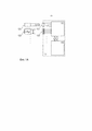
на фиг. 1A показана блок-схема известного универсального изолятора и известных вариантов возможности подключения с целью конфигурирования; in FIG. 1A shows a block diagram of a known universal insulator and known configuration options for connectivity;
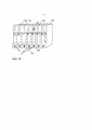
на фиг. 1В показан вид в перспективе установки множества таких известных универсальных изоляционных устройств при установке системы, например, при установке в изоляционном шкафу для использования применительно к искробезопасной системе;in FIG. 1B shows a perspective view of the installation of a plurality of such well-known universal insulation devices during installation of the system, for example, when installed in an insulation cabinet for use with an intrinsically safe system;
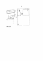
на фиг. 2А представлено схематическое изображение универсального изолятора в соответствии с вариантом реализации настоящего изобретения; а такжеin FIG. 2A is a schematic illustration of a universal insulator in accordance with an embodiment of the present invention; as well as
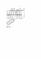
на фиг. 2В показан вид в перспективе группы универсальных изоляторов в соответствии с вариантом реализации настоящего изобретения, являющийся частью изоляционной системы внутри, например, изоляционного шкафа, входящего в состав искробезопасной системы.in FIG. 2B shows a perspective view of a group of universal insulators in accordance with an embodiment of the present invention, which is part of an insulation system inside, for example, an insulation cabinet, which is part of an intrinsically safe system.
В соответствии с фиг. 1А, предусмотрено схематичное изображение универсального изолятора, который может быть выполнен с возможностью, например, обеспечения изоляции применительно к полевым устройствам, выполненным с возможностью работы в искробезопасной среде.In accordance with FIG. 1A, a schematic representation of a universal insulator is provided, which can be configured, for example, to provide insulation for field devices configured to operate in an intrinsically safe environment.
Изолятор содержит элемент 111 микропроцессорного управления, связанный с энергонезависимым запоминающим устройством 112, обозначенным противоположно направленными стрелками. Комбинация элемента 111 микропроцессорного управления и энергонезависимого запоминающего устройства 112 обеспечивает подходящую одну из множества возможных конфигураций для изоляционного устройства, как того требует способ изоляции, например, в пределах цифровой области или аналоговой области, а также характер полевых устройств, подлежащих изоляции.The isolator comprises a
Конкретная конфигурация используемого изолятора 101 управляется путем использования блока конфигурации, который соединяется с элементом микропроцессорного управления посредством, например, штекерного разъема 121 или последовательного разъема 122. The specific configuration of the used
Как указано, штекерный разъем 121 выполнен с возможностью приема в гнезде 131, тогда как разъем 122 выполнен с возможностью приема в щелевом гнезде 132 разъема, как проиллюстрировано на фигуре.As indicated, the
Более подробная информация об использовании такого известного конфигурируемого универсального изолятора 101 приводится со ссылкой на фиг. 1В. В этом случае проиллюстрирована совокупность из семи изоляторов 101-107 и при этом одно (135) из гнезд выполнено с возможностью приема вилки 121, связанной с блоком конфигурации, для доставки данных конфигурации в сконфигурированный изолятор 105, который посредством освещения конкретным светодиодом 145 указывает на выбор и/или способ конфигурации.More detailed information on the use of such a known configurable
Следовательно, как будет понятно по ссылке на фиг. 1 и 2, конфигурация является невыгодным образом ограниченной, поскольку использование линии последовательной передачи данных приводит к определенной конфигурации, характерной только для технических требований к системе, тогда как использование вилки 121 требует наличия неповрежденных кабелей и подключения в конкретном месте согласно требованию.Therefore, as will be understood by reference to FIG. 1 and 2, the configuration is disadvantageously limited, since the use of the serial data line leads to a certain configuration specific to the technical requirements of the system, while the use of the
Далее в соответствии с фиг. 2А, представлено схематическое изображение одного варианта реализации настоящего изобретения.Further in accordance with FIG. 2A, a schematic representation of one embodiment of the present invention is presented.
На фиг. 2А проиллюстрирован конфигурируемый универсальный изолятор 201 в качестве примера конфигурируемого функционального устройства по настоящему изобретению и в котором используется элемент 211 управления микросистемой для использования в части способа конфигурации.In FIG. 2A illustrates the configurable
Однако, вместо последовательных входов/гнезд известных конфигурируемых универсальных изоляционных устройств, т.е. изоляционных устройств, в примере по настоящему изобретению, предлагаемом изолятором 201, используется блок RFID, имеющий небольшую антенну, обычно порядка 10 мм, а также предлагается функция энергонезависимого запоминающего устройства.However, instead of serial inputs / sockets of known configurable universal isolation devices, i.e. isolation devices, in the example of the present invention proposed by the
Таким образом, передача конфигурируемых данных в универсальный изолятор 201 и передача сконфигурированных данных из универсального изолятора 201 может быть выгодно использована беспроводным способом и с помощью особо экономичных и обычно доступных устройств связи, таких как известный смартфон 221 и ноутбук 222, а также другие устройства, такие как планшетные устройства с поддержкой обмена данными.Thus, the transmission of configurable data to the
Со ссылкой на фиг. 2В показано использование такого изолятора 201 по настоящему изобретению в качестве установки семи изоляционных устройств 201-207, в которых выбрано одно изоляционное устройство 205, и снова, как показано светодиодом 245 с подсветкой для соответствующей беспроводной/удаленной конфигурации, посредством своего устройства RFID (не показано на фиг. 2B) и смартфона 221 оператора.With reference to FIG. 2B illustrates the use of such an
Поэтому ясно, что функциональная возможность связи с элементом 211 микропроцессорного управления изолятора 201 по данному изобретению позволяет оператору конфигурировать изолятор 201 на расстоянии в любой ситуации, независимо от того, включено питание или нет, установлен ли он на стенде сборки, испытательном стенде, управляется ли он вручную оператором или вообще «на лету» в процессе производства, или при установке в месте эксплуатации.Therefore, it is clear that the functionality of communication with the
Таким образом, блок конфигурации может быть легко включен в широкодоступные устройства связи, такие как смартфоны, которые могут быть легко выполнены с возможностью связи с чипом RFID и которые обеспечивают особенно экономически выгодные альтернативы использованию известных ЭСППЗУ и соединителей, как известно из предшествующего уровня техники.Thus, the configuration unit can be easily incorporated into widely available communication devices, such as smartphones, which can be easily configured to communicate with the RFID chip and which provide particularly cost-effective alternatives to using the known EEPROM and connectors, as is known in the art.
Кроме того, оператор может легко идентифицировать, осматривать и проверять конфигурацию в любое время при нахождении в непосредственной близости от изоляционного устройства 201, и, если требуется, например, каждое из множества изоляционных устройств 201-207, как показано на фиг. 2В когда они, например, установлены в изоляционном шкафу, могут быть сконфигурированы одновременно посредством приема данных конфигурации от переносного устройства 221.In addition, the operator can easily identify, inspect and verify the configuration at any time while in the immediate vicinity of the
Разумеется, следует понимать, что настоящее изобретение не ограничивается конкретными подробностями вышеупомянутого варианта реализации изобретения, и дистанционная связь с конфигурируемым изоляционным устройством может осуществляться посредством любой подходящей технологии беспроводной передачи/приема, в том числе технологий с использованием протоколов связи ближнего радиуса действия (NFC), или иным образом.Of course, it should be understood that the present invention is not limited to the specific details of the aforementioned embodiment of the invention, and remote communication with a configurable isolation device can be carried out using any suitable wireless transmission / reception technology, including technologies using short-range communication protocols (NFC), or otherwise.
Поэтому конфигурация может быть успешно сохранена, даже если устройство выключено. Кроме того, не требуется прямого контакта с изоляционным устройством благодаря использованию передачи/приема данных беспроводной конфигурации, и, следовательно, способ конфигурации и последующей проверки может быть выполнен более надежным и эффективным способом, в частности, таким, который не создает проблемы ЭМС оператору.Therefore, the configuration can be successfully saved even if the device is turned off. In addition, direct contact with the isolation device is not required due to the use of transmitting / receiving wireless configuration data, and therefore, the configuration method and subsequent verification can be performed in a more reliable and efficient way, in particular, one that does not create an EMC problem for the operator.
Кроме того, если изолятор является искробезопасным устройством и если он установлен в зоне повышенной опасности, например, Зоне 2, в то время как конфигурация/связь на основе соединителей не была бы разрешена во время работы, такой тип связи, как описано в данном документе, был бы разрешен. In addition, if the isolator is an intrinsically safe device and if it is installed in a hazardous area, such as Zone 2, while the configuration / connection based on the connectors would not be allowed during operation, this type of connection as described in this document, would be allowed.
Claims (9)
Applications Claiming Priority (3)
| Application Number | Priority Date | Filing Date | Title |
|---|---|---|---|
| GBGB1603207.0A GB201603207D0 (en) | 2016-02-24 | 2016-02-24 | Electronic device configuration |
| GB1603207.0 | 2016-02-24 | ||
| PCT/GB2017/050188 WO2017144846A1 (en) | 2016-02-24 | 2017-01-25 | Electronic device configuration |
Publications (1)
| Publication Number | Publication Date |
|---|---|
| RU2704250C1 true RU2704250C1 (en) | 2019-10-25 |
Family
ID=55753121
Family Applications (1)
| Application Number | Title | Priority Date | Filing Date |
|---|---|---|---|
| RU2018132672A RU2704250C1 (en) | 2016-02-24 | 2017-01-25 | Configuration of electronic device |
Country Status (7)
| Country | Link |
|---|---|
| US (2) | US10811872B2 (en) |
| EP (1) | EP3420622B1 (en) |
| JP (1) | JP7174628B2 (en) |
| CN (1) | CN108886250B (en) |
| GB (1) | GB201603207D0 (en) |
| RU (1) | RU2704250C1 (en) |
| WO (1) | WO2017144846A1 (en) |
Citations (3)
| Publication number | Priority date | Publication date | Assignee | Title |
|---|---|---|---|---|
| RU2163047C2 (en) * | 1998-02-26 | 2001-02-10 | Телефонактиеболагет Лм Эрикссон (Пабл) | Connectors for interconnecting devices incorporating electric circuits |
| CN203084479U (en) * | 2013-01-15 | 2013-07-24 | 西安文理学院 | Isolation safety barrier |
| WO2015025267A1 (en) * | 2013-08-19 | 2015-02-26 | Koninklijke Philips N.V. | Programmable lighting device and method and system for programming lighting device |
Family Cites Families (31)
| Publication number | Priority date | Publication date | Assignee | Title |
|---|---|---|---|---|
| US1815233A (en) | 1927-07-11 | 1931-07-21 | Burke Electric Company | Terminal block |
| US4099216A (en) | 1976-11-12 | 1978-07-04 | Westinghouse Electric Corp. | Fuseless intrinsic safety barrier |
| US5144517A (en) | 1989-10-20 | 1992-09-01 | Pepperl + Fuchs, Inc. | Intrinsically safe barrier device |
| IT1244115B (en) | 1990-11-29 | 1994-07-05 | Elcon Instr Srl | CONNECTION SYSTEM FOR INDUSTRIAL INSTRUMENTATION INSTRUMENTATION CABLES |
| US5564086A (en) * | 1993-11-29 | 1996-10-08 | Motorola, Inc. | Method and apparatus for enhancing an operating characteristic of a radio transmitter |
| US6054780A (en) | 1997-10-23 | 2000-04-25 | Analog Devices, Inc. | Magnetically coupled signal isolator using a Faraday shielded MR or GMR receiving element |
| DE19829528C1 (en) | 1998-07-02 | 2000-02-24 | Ulrich Weitzel | Line distributor for telecommunications and security systems |
| US6384350B1 (en) | 1999-08-02 | 2002-05-07 | Meter Devices Company | Meter test switch |
| US6885949B2 (en) | 2002-07-24 | 2005-04-26 | Smar Research Corporation | System and method for measuring system parameters and process variables using multiple sensors which are isolated by an intrinsically safe barrier |
| US7075329B2 (en) * | 2003-04-30 | 2006-07-11 | Analog Devices, Inc. | Signal isolators using micro-transformers |
| JP4532856B2 (en) | 2003-07-08 | 2010-08-25 | キヤノン株式会社 | Position and orientation measurement method and apparatus |
| US7148738B2 (en) * | 2004-02-17 | 2006-12-12 | Siemens Energy & Automation, Inc. | Systems, devices, and methods for providing control signals |
| JP2005333169A (en) | 2004-05-18 | 2005-12-02 | Sony Corp | Wireless communication system and wireless communication device |
| US8441325B2 (en) * | 2004-06-03 | 2013-05-14 | Silicon Laboratories Inc. | Isolator with complementary configurable memory |
| US20060202443A1 (en) | 2005-03-09 | 2006-09-14 | The Holland Group, Inc. | Fifth wheel slider assembly |
| US20070247768A1 (en) | 2006-04-21 | 2007-10-25 | Square D Company | Wireless handheld device and circuit breaker |
| US7825776B2 (en) | 2006-08-17 | 2010-11-02 | Intel Corporation | Device configuration with RFID |
| GB0816121D0 (en) * | 2008-09-04 | 2008-10-15 | Mtl Instr Group The Plc | Multispur fieldbus barrier arrangement |
| US8212388B2 (en) | 2008-11-07 | 2012-07-03 | International Business Machines Corporation | Multi-capacity power supply for electronic devices |
| TW201032059A (en) * | 2009-02-27 | 2010-09-01 | Io Interconnect Ltd | Configurable wireless universal serial bus (USB) module |
| US9035766B2 (en) | 2010-07-07 | 2015-05-19 | Honeywell International Inc. | System and method of determining gas detector information and status via RFID tags |
| JP5087666B2 (en) * | 2010-09-30 | 2012-12-05 | 株式会社東芝 | Information processing apparatus and communication control method |
| EP2701255B1 (en) | 2012-08-23 | 2016-05-04 | General Electric Technology GmbH | Circuit interruption device |
| GB201304957D0 (en) | 2013-03-19 | 2013-05-01 | Kitchener Renato | New generation fieldbus self organising power system |
| US20150065065A1 (en) * | 2013-09-03 | 2015-03-05 | Broadcom Corporation | Rf transceiver with isolation transformer and methods for use therewith |
| SG2013074323A (en) | 2013-10-03 | 2015-05-28 | Schneider Electric South East Asia Hq Pte Ltd | A switching device and a method of controlling the same |
| CN104615093B (en) | 2013-10-28 | 2018-04-20 | 费希尔控制国际公司 | Essential safety voltage clamp equipment |
| US20150296598A1 (en) | 2014-04-11 | 2015-10-15 | Infineon Technologies Ag | Contactless Device Configuration |
| US9875650B2 (en) * | 2014-04-18 | 2018-01-23 | Gentex Corporation | Trainable transceiver and mobile communications device diagnostic systems and methods |
| US9946240B2 (en) | 2015-01-30 | 2018-04-17 | Fisher-Rosemount Systems, Inc. | Apparatus to communicatively couple three-wire field devices to controllers in a process control system |
| GB201603108D0 (en) * | 2016-02-23 | 2016-04-06 | Cooper Technologies Co | Configurable isolator |
-
2016
- 2016-02-24 GB GBGB1603207.0A patent/GB201603207D0/en not_active Ceased
-
2017
- 2017-01-25 WO PCT/GB2017/050188 patent/WO2017144846A1/en active Application Filing
- 2017-01-25 EP EP17707092.7A patent/EP3420622B1/en active Active
- 2017-01-25 CN CN201780021907.8A patent/CN108886250B/en active Active
- 2017-01-25 JP JP2018544778A patent/JP7174628B2/en active Active
- 2017-01-25 RU RU2018132672A patent/RU2704250C1/en active
- 2017-01-25 US US16/079,875 patent/US10811872B2/en active Active
-
2020
- 2020-09-28 US US17/034,358 patent/US11316339B2/en active Active
Patent Citations (3)
| Publication number | Priority date | Publication date | Assignee | Title |
|---|---|---|---|---|
| RU2163047C2 (en) * | 1998-02-26 | 2001-02-10 | Телефонактиеболагет Лм Эрикссон (Пабл) | Connectors for interconnecting devices incorporating electric circuits |
| CN203084479U (en) * | 2013-01-15 | 2013-07-24 | 西安文理学院 | Isolation safety barrier |
| WO2015025267A1 (en) * | 2013-08-19 | 2015-02-26 | Koninklijke Philips N.V. | Programmable lighting device and method and system for programming lighting device |
Also Published As
| Publication number | Publication date |
|---|---|
| EP3420622B1 (en) | 2023-07-19 |
| US20190027926A1 (en) | 2019-01-24 |
| JP2019519012A (en) | 2019-07-04 |
| CN108886250B (en) | 2020-12-22 |
| GB201603207D0 (en) | 2016-04-06 |
| JP7174628B2 (en) | 2022-11-17 |
| US10811872B2 (en) | 2020-10-20 |
| US20210013710A1 (en) | 2021-01-14 |
| CN108886250A (en) | 2018-11-23 |
| WO2017144846A1 (en) | 2017-08-31 |
| US11316339B2 (en) | 2022-04-26 |
| EP3420622A1 (en) | 2019-01-02 |
Similar Documents
| Publication | Publication Date | Title |
|---|---|---|
| RU2467373C2 (en) | Improved form factor and electromagnetic interference protection for process device wireless adapters | |
| JP6568115B2 (en) | Intrinsically safe in-line adapter with built-in capacitive barrier for connecting wireless modules and antennas | |
| US20090273334A1 (en) | System and Method for Efficient Association of a Power Outlet and Device | |
| JP2018508916A5 (en) | ||
| US11011823B2 (en) | Automation field device | |
| WO2013130432A1 (en) | Connector having wireless control capabilities | |
| CN101772893B (en) | Link coupled antenna system on a field device having a grounded housing | |
| RU2704250C1 (en) | Configuration of electronic device | |
| CA2722920C (en) | System and method for efficient association of a power outlet and device | |
| RU2686282C1 (en) | Electronic insulating device | |
| WO2018102405A1 (en) | Systems and methods for determining cable end location | |
| RU2741317C2 (en) | Electronic device disconnector | |
| US11070011B2 (en) | Remotely configurable connector | |
| US11146065B2 (en) | Energy management capsule | |
| EP4301097A1 (en) | A system and a method for commissioning of lighting system elements | |
| CN103782567A (en) | Method and apparatus for secure modification of a configuration setting in a network device | |
| CN108027599A (en) | Field device with the radio module that can be started by operating element | |
| JP2011120068A (en) | Ic card type on-site operation device | |
| CN104953394A (en) | Wireless intelligent socket and implementation method therefor | |
| KR20120078920A (en) | Rotary type consol connection device |