RU2702911C2 - Quiet mr-visualization - Google Patents
Quiet mr-visualization Download PDFInfo
- Publication number
- RU2702911C2 RU2702911C2 RU2017124584A RU2017124584A RU2702911C2 RU 2702911 C2 RU2702911 C2 RU 2702911C2 RU 2017124584 A RU2017124584 A RU 2017124584A RU 2017124584 A RU2017124584 A RU 2017124584A RU 2702911 C2 RU2702911 C2 RU 2702911C2
- Authority
- RU
- Russia
- Prior art keywords
- magnetic field
- gradient
- certain number
- vector
- pulses
- Prior art date
Links
Images
Classifications
-
- G—PHYSICS
- G01—MEASURING; TESTING
- G01R—MEASURING ELECTRIC VARIABLES; MEASURING MAGNETIC VARIABLES
- G01R33/00—Arrangements or instruments for measuring magnetic variables
- G01R33/20—Arrangements or instruments for measuring magnetic variables involving magnetic resonance
- G01R33/44—Arrangements or instruments for measuring magnetic variables involving magnetic resonance using nuclear magnetic resonance [NMR]
- G01R33/48—NMR imaging systems
- G01R33/4818—MR characterised by data acquisition along a specific k-space trajectory or by the temporal order of k-space coverage, e.g. centric or segmented coverage of k-space
- G01R33/4824—MR characterised by data acquisition along a specific k-space trajectory or by the temporal order of k-space coverage, e.g. centric or segmented coverage of k-space using a non-Cartesian trajectory
- G01R33/4826—MR characterised by data acquisition along a specific k-space trajectory or by the temporal order of k-space coverage, e.g. centric or segmented coverage of k-space using a non-Cartesian trajectory in three dimensions
-
- G—PHYSICS
- G01—MEASURING; TESTING
- G01R—MEASURING ELECTRIC VARIABLES; MEASURING MAGNETIC VARIABLES
- G01R33/00—Arrangements or instruments for measuring magnetic variables
- G01R33/20—Arrangements or instruments for measuring magnetic variables involving magnetic resonance
- G01R33/44—Arrangements or instruments for measuring magnetic variables involving magnetic resonance using nuclear magnetic resonance [NMR]
- G01R33/48—NMR imaging systems
- G01R33/4816—NMR imaging of samples with ultrashort relaxation times such as solid samples, e.g. MRI using ultrashort TE [UTE], single point imaging, constant time imaging
-
- G—PHYSICS
- G01—MEASURING; TESTING
- G01R—MEASURING ELECTRIC VARIABLES; MEASURING MAGNETIC VARIABLES
- G01R33/00—Arrangements or instruments for measuring magnetic variables
- G01R33/20—Arrangements or instruments for measuring magnetic variables involving magnetic resonance
- G01R33/44—Arrangements or instruments for measuring magnetic variables involving magnetic resonance using nuclear magnetic resonance [NMR]
- G01R33/48—NMR imaging systems
- G01R33/54—Signal processing systems, e.g. using pulse sequences ; Generation or control of pulse sequences; Operator console
- G01R33/56—Image enhancement or correction, e.g. subtraction or averaging techniques, e.g. improvement of signal-to-noise ratio and resolution
- G01R33/563—Image enhancement or correction, e.g. subtraction or averaging techniques, e.g. improvement of signal-to-noise ratio and resolution of moving material, e.g. flow contrast angiography
- G01R33/56341—Diffusion imaging
Abstract
Description
Область техники, к которой относится изобретениеFIELD OF THE INVENTION
Изобретение относится к области техники магнитно-резонансной (MR) визуализации. Оно связано со способом MR-визуализации. Изобретение также относится к MR-устройству и к компьютерной программе, которая должна выполняться на MR-устройстве.The invention relates to the field of magnetic resonance imaging (MR) imaging. It is associated with the MR imaging method. The invention also relates to an MR device and to a computer program to be executed on an MR device.
Уровень техникиState of the art
MR-способы для формирования изображений, которые используют взаимодействие между магнитными полями и ядерными спинами, чтобы формировать двумерные или трехмерные изображения, широко используются в настоящее время, а именно в области техники медицинской диагностики, поскольку для визуализации мягких тканей они превосходят другие способы формирования изображений во многих отношениях, не требуют ионизирующего излучения и обычно не инвазивны.MR imaging methods that use the interaction between magnetic fields and nuclear spins to form two-dimensional or three-dimensional images are widely used at present, namely in the field of medical diagnostic technology, because they are superior to other methods of imaging in soft tissue imaging in in many ways, do not require ionizing radiation and are usually not invasive.
Согласно MR-способу, в общем, тело пациента, который должен исследоваться, помещается в сильное однородное магнитное поле (B0-поле), направление которого одновременно задает ось (обычно ось Z) системы координат, на которой основано измерение. Магнитное поле формирует различные энергетические уровни для отдельных ядерных спинов в зависимости от напряженности магнитного поля. Переходы между этими энергетическими уровнями могут возбуждаться (спиновой резонанс) посредством приложения электромагнитного переменного поля (RF-поля, также называемого "B1-полем") заданной частоты (так называемой ларморовской частоты или MR-частоты). С макроскопической точки зрения, распределение отдельных ядерных спинов формирует полное намагничивание, которое может отклоняться от состояния равновесия посредством приложения электромагнитного импульса надлежащей частоты (RF-импульса), так что намагничивание выполняет прецессионное движение вокруг оси Z. Прецессионное движение описывает поверхность конуса, угол апертуры которой упоминается как угол переворота. Абсолютная величина угла переворота зависит от интенсивности и длительности приложенного электромагнитного импульса.According to the MR method, in general, the patient’s body to be examined is placed in a strong uniform magnetic field (B 0 field), the direction of which simultaneously defines the axis (usually the Z axis) of the coordinate system on which the measurement is based. The magnetic field forms various energy levels for individual nuclear spins depending on the magnetic field strength. Transitions between these energy levels can be excited (spin resonance) by applying an electromagnetic alternating field (RF field, also called a “B 1 field”) of a given frequency (the so-called Larmor frequency or MR frequency). From a macroscopic point of view, the distribution of individual nuclear spins forms a complete magnetization, which can deviate from the equilibrium state by applying an electromagnetic pulse of the proper frequency (RF pulse), so that the magnetization performs a precession motion around the Z axis. The precession motion describes the surface of the cone, whose aperture angle is referred to as the angle of revolution. The absolute value of the flip angle depends on the intensity and duration of the applied electromagnetic pulse.
После окончания RF-импульса, намагничивание возвращается в исходное состояние равновесия, в котором намагничивание в направлении по оси Z снова увеличивается с первой постоянной T1 времени (временем спин-решеточной или продольной релаксации), а намагничивание в перпендикулярном направлении к направлению по оси Z расслабляется со второй постоянной T2 времени (временем спин-спиновой или поперечной релаксации). Варьирование намагничивания может обнаруживаться посредством одной или более приемных RF-катушек, которые размещаются и ориентируются в объеме исследования MR-устройства таким образом, что варьирование намагничивания измеряется в перпендикулярном направлении к оси Z.After the end of the RF pulse, the magnetization returns to its initial equilibrium state, in which the magnetization in the Z axis direction again increases with the first time constant T1 (spin-lattice or longitudinal relaxation time), and the magnetization in the perpendicular direction to the Z axis relaxes second time constant T2 (spin-spin or transverse relaxation time). The variation of magnetization can be detected by one or more receiving RF coils, which are placed and oriented in the scope of the MR device so that the variation of magnetization is measured in the perpendicular direction to the Z axis.
Чтобы реализовывать пространственное разрешение в теле, градиенты линейного магнитного поля, идущие вдоль трех главных осей, накладываются на однородное магнитное поле, приводя к линейной пространственной зависимости спиновой резонансной частоты. Сигнал, снимаемый в приемных катушках, в таком случае содержит компоненты различных частот, которые могут быть ассоциированы с различными местоположениями в теле. Сигнальные MR-данные, полученные через RF-катушки, соответствуют пространственной частотной области и называются данными k-пространства. Набор данных k-пространства преобразуется в MR-изображение посредством преобразования Фурье или других надлежащих алгоритмов восстановления.In order to realize spatial resolution in the body, the linear magnetic field gradients along the three principal axes are superimposed on the uniform magnetic field, leading to a linear spatial dependence of the spin resonance frequency. The signal recorded in the receiving coils, in this case, contains components of different frequencies, which can be associated with different locations in the body. The signal MR data obtained through the RF coils correspond to the spatial frequency domain and are called k-space data. The k-space dataset is converted to an MR image by Fourier transform or other appropriate reconstruction algorithms.
В традиционных сеансах MR-визуализации возникает значительный уровень акустического шума, который вызывается посредством механических колебаний магнитных полевых градиентных катушек, помещенных в статическое основное магнитное поле. Лоренцевы силы, вызываемые, когда электрический ток прикладывается к градиентным катушкам, заставляют их физически перемещаться. Это смещение зависит от напряженности статического магнитного поля, амплитуды приложенного электрического тока и частоты и формы сигнала переключения градиента магнитного поля. Амплитуда акустического шума в объеме исследования устройства MR-визуализации обычно варьируется от 94 до 135 дБ в зависимости от различных параметров: аппаратных характеристик соответствующего устройства MR-визуализации, степени вибрации системы, типа и параметров (например, времени повторения) применяемой последовательности MR-визуализации, числа полученных срезов и т.д. Высокий уровень акустического шума приводит к стрессу и дискомфорту исследуемых пациентов. Защита органов слуха требуется для того, чтобы предотвращать нарушение слуха.In traditional MR imaging sessions, a significant level of acoustic noise occurs, which is caused by mechanical vibrations of the magnetic field gradient coils placed in a static main magnetic field. Lorentz forces, caused when an electric current is applied to the gradient coils, cause them to physically move. This bias depends on the strength of the static magnetic field, the amplitude of the applied electric current and the frequency and waveform of the magnetic field gradient switching. The amplitude of acoustic noise in the volume of research of the MR imaging device usually varies from 94 to 135 dB depending on various parameters: the hardware characteristics of the corresponding MR imaging device, the degree of vibration of the system, the type and parameters (for example, repetition time) of the MR imaging sequence used, the number of slices received, etc. The high level of acoustic noise leads to stress and discomfort of the studied patients. Hearing protection is required to prevent hearing impairment.
Недостатки акустического шума могут преодолеваться посредством недавно разработанных технологий фактически бесшумной MR-визуализации, в которых RF-возбуждение, а также получение MR-сигналов выполняется в присутствии градиента магнитного поля. Градиент магнитного поля применяется исключительно для кодирования в радиальном внецентровом k-пространстве после частотного кодирования. В этих известных подходах, пространственно неизбирательное возбуждение должно однородно покрывать полную полосу пропускания частот, охватываемую посредством считываемого градиента магнитного поля, что обычно достигается посредством излучения коротких твердых RF-импульсов. Получение сигнала затухания свободной индукции (FID) начинается сразу после излучения RF-импульса. После FID-считывания, только минимальное время требуется для задания следующего считываемого градиента магнитного поля до того, как может прикладываться следующий RF-импульс, за счет этого обеспечивая очень небольшие времена повторения (TR). Градиентный вектор магнитного поля, определяющий направление считывания, инкрементно варьируется в зависимости от повторения до тех пор, пока сферический объем в k-пространстве не будет дискретизирован до требуемой степени. Такие технологии сканирования в радиальном внецентровом k-пространстве иногда упоминаются в качестве сканирования по принципу "резинового мяча", при котором "лучи" в радиальном k-пространстве и их компоновка в k-пространстве напоминает нити (веревки) известной конструкции игрушечного мяча. Без необходимости для отключения считываемого градиента магнитного поля в ходе всего сканирования, MR-визуализация может выполняться фактически бесшумно (см., например, работу авторов Weiger и др. "Magnetic Resonance in Medicine", издание 70, стр. 328-332, 2013 год). Дополнительно, патент (США) US5570018 упоминает пространственное кодирование магнитного резонансного сигнала посредством синусоидального варьирования магнитных градиентных полей в двух ортогональных направлениях (по оси y и z) и с использованием периодов, которые отличаются на коэффициент «два».The disadvantages of acoustic noise can be overcome by newly developed technologies for virtually silent MR imaging, in which RF excitation as well as receiving MR signals is performed in the presence of a magnetic field gradient. The magnetic field gradient is used exclusively for coding in radial off-center k-space after frequency coding. In these known approaches, spatially non-selective excitation should uniformly cover the entire frequency bandwidth covered by a readable magnetic field gradient, which is usually achieved by emitting short solid RF pulses. The acquisition of the free induction decay signal (FID) begins immediately after the emission of the RF pulse. After the FID readout, only the minimum time is required to set the next readable magnetic field gradient before the next RF pulse can be applied, thereby providing very short repetition times (TR). The gradient vector of the magnetic field, which determines the direction of reading, varies incrementally depending on the repetition until the spherical volume in k-space is discretized to the required degree. Such scanning technologies in radial off-center k-space are sometimes referred to as “rubber ball” scanning, in which the “rays” in radial k-space and their arrangement in k-space resemble the threads (ropes) of the known toy ball design. Without the need to turn off the readable magnetic field gradient during the entire scan, MR imaging can be performed virtually silently (see, for example, authors Weiger et al. "Magnetic Resonance in Medicine", 70 edition, pp. 328-332, 2013 ) Additionally, US patent US5570018 mentions spatial coding of a magnetic resonance signal by sinusoidally varying the magnetic gradient fields in two orthogonal directions (along the y and z axis) and using periods that differ by a factor of “two”.
В действительности, известные технологии бесшумного кодирования в радиальном внецентровом k-пространстве обеспечивают только взвешенную по протонной плотности контрастность восстановленного MR-изображения.In fact, the well-known silent coding techniques in radial off-center k-space provide only proton-weighted contrast of the reconstructed MR image.
Сущность изобретения.SUMMARY OF THE INVENTION
Из вышеприведенного следует легко принимать во внимание, что существует потребность в усовершенствованном способе MR-визуализации. Цель изобретения заключается в том, чтобы предоставлять бесшумную/тихую MR-визуализацию с T2-(или T2*)-взвешенной или диффузно-взвешенной контрастностью.From the above, it should be readily taken into account that there is a need for an improved MR imaging method. The purpose of the invention is to provide silent / quiet MR imaging with T2- (or T2 *) -weighted or diffusely-weighted contrast.
В соответствии с изобретением, раскрыт способ MR-визуализации объекта, позиционированного в объеме исследования MR-устройства. Способ настоящего изобретения содержит этапы:In accordance with the invention, a method for MR imaging of an object positioned in the scope of an MR device is disclosed. The method of the present invention comprises the steps of:
- возбуждения намагничивания, с использованием последовательности RF-импульсов, в присутствии постепенно изменяющегося градиента магнитного поля;- magnetization excitation, using a sequence of RF pulses, in the presence of a gradually changing magnetic field gradient;
- модификации значения градиента таким образом, что в последующий момент времени последовательность эха формируется согласно вышеуказанным RF-импульсам.- modifying the gradient value so that at a subsequent point in time, an echo sequence is formed according to the above RF pulses.
В одном варианте осуществления изобретения (варианте осуществления на основе "полевого эха"), способ содержит следующие этапы:In one embodiment of the invention (“field echo” based embodiment), the method comprises the following steps:
- подвергание объекта последовательности визуализации, содержащее:- subject exposure to a visualization sequence comprising:
a) постепенное варьирование градиентного вектора магнитного поля от начальной позиции к конечной позиции по множеству промежуточных позиций пока определенное число RF-импульсов излучается в присутствии градиента магнитного поля;a) the gradual variation of the gradient vector of the magnetic field from the initial position to the final position in many intermediate positions while a certain number of RF pulses are emitted in the presence of a magnetic field gradient;
b) постепенное варьирование градиентного вектора магнитного поля снова от начальной позиции к конечной позиции по множеству промежуточных позиций пока определенное число MR-эхо-сигналов получается в присутствии градиента магнитного поля;b) the gradual variation of the gradient vector of the magnetic field again from the initial position to the final position in many intermediate positions until a certain number of MR echo signals are obtained in the presence of a magnetic field gradient;
c) дискретизация сферического объема в k-пространстве посредством повторения этапов a) и b) определенное число раз для различных начальных, промежуточных и конечных позиций;c) discretization of a spherical volume in k-space by repeating steps a) and b) a certain number of times for different initial, intermediate and final positions;
- восстановление магнитно-резонансного изображения из полученных MR-эхо-сигналов.- restoration of the magnetic resonance image from the received MR echo signals.
Согласно этому варианту осуществления, градиент магнитного поля постепенно изменяет направление (и необязательно также интенсивность) на этапе a). Вектор градиента магнитного поля начинается в начальной позиции (определенной посредством начальных значений интенсивности и направления градиента магнитного поля) и заканчивается в конечной позиции (определенной посредством конечных значений интенсивности и направления градиента магнитного поля) в ходе каждого повторения этапа a). Каждая позиция на траектории, соединяющей промежуточные позиции градиентного вектора магнитного поля, проходится дважды, согласно способу изобретения, первый раз на этапе a), во второй раз на этапе b). Градиент магнитного поля остается включенным на каждом из этапов a) и b). Между этапами a) и b) градиентный вектор магнитного поля должен варьироваться обратно (без отключения) от конечной позиции к начальной позиции таким образом, что временной интеграл градиента магнитного поля (момента нулевого порядка) по траектории этапов a) и b), т.е. от соответствующей начальной позиции к соответствующей конечной позиции и обратно к начальной позиции равен (точно) нулю.According to this embodiment, the magnetic field gradient gradually changes direction (and optionally also intensity) in step a). The magnetic field gradient vector begins at the initial position (determined by the initial values of the intensity and direction of the magnetic field gradient) and ends at the final position (determined by the final values of the intensity and direction of the magnetic field gradient) during each repetition of step a). Each position on the path connecting the intermediate positions of the gradient vector of the magnetic field is traversed twice, according to the method of the invention, the first time in step a), the second time in step b). The magnetic field gradient remains on at each of steps a) and b). Between steps a) and b) the gradient vector of the magnetic field should vary back (without disconnecting) from the end position to the initial position so that the time integral of the gradient of the magnetic field (moment of zero order) along the path of steps a) and b), i.e. . from the corresponding starting position to the corresponding ending position and back to the starting position is (exactly) zero.
Временной интервал между этапами a) и b) (эхо-время) может выбираться в диапазоне между 10 мс и 500 мс. Во время первого прохода (этапа a) твердые RF-импульсы излучаются обычно каждые 1-2 мс. Во время второго прохода (этапа b) MR-эхо-сигналы получаются в качестве выборок в радиальном k-пространстве (без излучения RF-импульсов) согласно мгновенной интенсивности и направлению градиента магнитного поля. Полный сферический объем k-пространства дискретизирован посредством повторения этапов a)-b), при этом начальная и конечная позиции и/или траектории градиентного вектора магнитного поля варьируются в зависимости от повторения. MR-изображение, в итоге восстановленное из полученных MR-эхо-сигналов, внутренне обеспечивает T2*-контрастность. В возможном варианте осуществления изобретения начальная и конечная позиции градиентного вектора магнитного поля могут быть идентичными в одном или более повторений этапов a) и b).The time interval between steps a) and b) (echo time) can be selected between 10 ms and 500 ms. During the first pass (step a), solid RF pulses are usually emitted every 1-2 ms. During the second pass (step b), MR echoes are obtained as samples in radial k-space (without emitting RF pulses) according to the instantaneous intensity and direction of the magnetic field gradient. The full spherical volume of k-space is discretized by repeating steps a) -b), while the initial and final positions and / or trajectories of the magnetic field gradient vector vary depending on the repetition. The MR image, ultimately reconstructed from the received MR echoes, internally provides T2 * contrast. In a possible embodiment, the start and end positions of the magnetic field gradient vector may be identical in one or more repetitions of steps a) and b).
Градиент магнитного поля предпочтительно варьируется вдоль плавной траектории. Частоты градиента магнитного поля, требуемые посредством способа изобретения, обычно находятся в диапазоне от 10 Гц до 100 Гц, который ограничивает акустический шум, а также потребности по скорости слежения в аппаратных средствах используемого MR-устройства.The magnetic field gradient preferably varies along a smooth path. The magnetic field gradient frequencies required by the method of the invention are usually in the range of 10 Hz to 100 Hz, which limits acoustic noise, as well as the tracking speed requirements in the hardware of the MR device used.
Диффузно-контрастное MR-изображение может получаться посредством использования различных траекторий вектора градиентного магнитного поля (что приводит к различным моментам первого порядка, наблюдаемым посредством полученных MR-эхо-сигналов) и посредством вычисления соответствующих характеристик диффузии из них.A diffuse-contrast MR image can be obtained by using different trajectories of the gradient magnetic field vector (which leads to different first-order moments observed by the received MR echo signals) and by calculating the corresponding diffusion characteristics from them.
В предпочтительном варианте осуществления изобретения, градиентный вектор магнитного поля варьируется вдоль идентичных траекторий на этапах a) и b) таким образом, что четко определенные позиции в k-пространстве могут быть приписаны каждому из полученных MR-эхо-сигналов.In a preferred embodiment, the magnetic field gradient vector varies along identical paths in steps a) and b) so that well-defined k-space positions can be assigned to each of the received MR echoes.
В дополнительном предпочтительном варианте осуществления, градиентный вектор магнитного поля варьируется вдоль замкнутой круговой траектории, центрированной на начале системы координат градиента магнитного поля. Это приводит к простой и прямой реализации способа изобретения. Временной интеграл градиента магнитного поля по полной круговой траектории автоматически равен нулю (при условии, что скорость варьирования градиентного вектора магнитного поля вдоль круговой траектории является постоянной). Полный объем в k-пространстве может быть дискретизирован посредством выбора меридианов сферических объемов в k-пространстве в качестве круговых траекторий градиентного вектора магнитного поля, при этом азимутальный угол меридиана постепенно увеличивается в зависимости от повторения этапов a) и b).In a further preferred embodiment, the magnetic field gradient vector varies along a closed circular path centered at the origin of the magnetic field gradient coordinate system. This leads to a simple and direct implementation of the method of the invention. The time integral of the magnetic field gradient along the full circular path is automatically zero (provided that the rate of variation of the magnetic field gradient vector along the circular path is constant). The total volume in k-space can be discretized by choosing the meridians of spherical volumes in k-space as circular trajectories of the gradient vector of the magnetic field, while the azimuthal angle of the meridian gradually increases depending on the repetition of steps a) and b).
В альтернативном варианте осуществления (варианте осуществления на основе "спинового эха"), способ содержит следующие этапы:In an alternative embodiment (spin echo embodiment), the method comprises the following steps:
- подвергание объекта последовательности визуализации, содержащее:- subject exposure to a visualization sequence comprising:
a) постепенное варьирование градиентного вектора магнитного поля от начальной позиции к конечной позиции по множеству промежуточных позиций пока определенное число RF-импульсов излучается в присутствии градиента магнитного поля;a) the gradual variation of the gradient vector of the magnetic field from the initial position to the final position in many intermediate positions while a certain number of RF pulses are emitted in the presence of a magnetic field gradient;
b) варьирование вектора магнитного поля по направлению к нулю;b) variation of the magnetic field vector towards zero;
c) приложение перефокусирующего RF-импульса;c) application of a refocusing RF pulse;
d) варьирование вектора магнитного поля к вышеуказанной конечной позиции;d) varying the magnetic field vector to the above end position;
e) постепенное варьирование градиентного вектора магнитного поля от конечной позиции к начальной позиции, в обратном порядке по множеству промежуточных позиций пока определенное число MR-эхо-сигналов получается в присутствии градиента магнитного поля;e) the gradual variation of the gradient vector of the magnetic field from the final position to the initial position, in the reverse order for many intermediate positions until a certain number of MR echo signals are obtained in the presence of a magnetic field gradient;
f) дискретизация сферического объема в k-пространстве посредством повторения этапов a)-e) определенное число раз для различных начальных, промежуточных и конечных позиций;f) discretization of a spherical volume in k-space by repeating steps a) -e) a certain number of times for different initial, intermediate and final positions;
- восстановление магнитно-резонансного изображения из полученных MR-эхо-сигналов.- restoration of the magnetic resonance image from the received MR echo signals.
Согласно этому варианту осуществления, градиент магнитного поля постепенно изменяет направление (и необязательно также интенсивность) на этапе a). Вектор градиента магнитного поля начинается в начальной позиции (определенной посредством начальных значений интенсивности и направления градиента магнитного поля) и заканчивается в конечной позиции (определенной посредством конечных значений интенсивности и направления градиента магнитного поля) в ходе каждого повторения этапа a). Каждая позиция на траектории, соединяющей промежуточные позиции градиентного вектора магнитного поля, проходится дважды, согласно способу изобретения, первый раз на этапе a), и второй раз, но в обратном порядке, на этапе e). Градиент магнитного поля остается включенным на каждом из этапов a) и e).According to this embodiment, the magnetic field gradient gradually changes direction (and optionally also intensity) in step a). The magnetic field gradient vector begins at the initial position (determined by the initial values of the intensity and direction of the magnetic field gradient) and ends at the final position (determined by the final values of the intensity and direction of the magnetic field gradient) during each repetition of step a). Each position on the path connecting the intermediate positions of the gradient vector of the magnetic field is traversed twice, according to the method of the invention, the first time in step a), and the second time, but in reverse order, in step e). The magnetic field gradient remains on at each of steps a) and e).
Временной интервал между этапами a) и e) (эхо-время) может выбираться в диапазоне между 10 мс и 500 мс. Во время первого прохода (этапа a) твердые RF-импульсы излучаются, обычно каждые 1-2 мс. Во время второго прохода (этапа e) MR-эхо-сигналы получаются в качестве выборок в радиальном k-пространстве (без излучения RF-импульсов) согласно мгновенной интенсивности и направлению градиента магнитного поля. Полный сферический объем k-пространства дискретизирован посредством повторения этапов a)-e), при этом начальная и конечная позиции и/или траектории градиентного вектора магнитного поля варьируются в зависимости от повторения. MR-изображение, в итоге восстановленное из полученных MR-эхо-сигналов, внутренне обеспечивает T2-контрастность. В возможном варианте осуществления изобретения начальная и конечная позиции градиентного вектора магнитного поля могут быть идентичными в одном или более повторений этапов a)-e).The time interval between steps a) and e) (echo time) can be selected between 10 ms and 500 ms. During the first pass (step a), solid RF pulses are emitted, usually every 1-2 ms. During the second pass (step e), the MR echo signals are obtained as samples in the radial k-space (without emitting RF pulses) according to the instantaneous intensity and direction of the magnetic field gradient. The full spherical volume of k-space is discretized by repeating steps a) -e), while the initial and final positions and / or trajectories of the magnetic field gradient vector vary depending on the repetition. The MR image, ultimately reconstructed from the received MR echoes, internally provides T2 contrast. In a possible embodiment, the start and end positions of the magnetic field gradient vector may be identical in one or more repetitions of steps a) to e).
Градиент магнитного поля предпочтительно варьируется вдоль плавной траектории. Частоты градиента магнитного поля, требуемые посредством способа изобретения, обычно находятся в диапазоне от 10 Гц до 200 Гц, который ограничивает акустический шум, а также потребности по скорости слежения в аппаратных средствах используемого MR-устройства.The magnetic field gradient preferably varies along a smooth path. The magnetic field gradient frequencies required by the method of the invention are typically in the range of 10 Hz to 200 Hz, which limits acoustic noise, as well as the tracking speed requirements in the hardware of the MR device used.
В альтернативном варианте осуществления, градиентный вектор магнитного поля варьируется вдоль замкнутой траектории теннисного мяча. Траектория теннисного мяча (напоминающая кривую типичного шва теннисного мяча) понимается как кривая, которая задается посредством пересечения сферы и гиперболического параболоида. С другой стороны, с учетом "варианта осуществления на основе полевого эха", временной интеграл градиента магнитного поля по полной траектории теннисного мяча автоматически равен нулю (при условии, что скорость варьирования градиентного вектора магнитного поля вдоль траектории является постоянной, и что траектория теннисного мяча центрируется на начале системы координат градиента магнитного поля). Тем не менее, длина траектории и в силу этого эффективное эхо-время полученных MR-эхо-сигналов может варьироваться целевым способом посредством надлежащего выбора параметров кривой теннисного мяча. Таким образом, появляется возможность, например, получать диффузно-контрастное MR-изображение. Вариант осуществления на основе SE включает в себя дополнительное отклонение в позицию Gx, y=0.In an alternative embodiment, the gradient vector of the magnetic field varies along the closed path of the tennis ball. The trajectory of a tennis ball (resembling a curve of a typical seam of a tennis ball) is understood as a curve that is defined by the intersection of a sphere and a hyperbolic paraboloid. On the other hand, in view of the “field echo-based embodiment”, the time integral of the magnetic field gradient along the full path of the tennis ball is automatically zero (provided that the rate of variation of the magnetic field gradient vector along the path is constant, and that the path of the tennis ball is centered at the beginning of the coordinate system of the magnetic field gradient). However, the path length and therefore the effective echo time of the received MR echoes can be varied in a targeted manner by properly selecting the parameters of the tennis ball curve. Thus, it becomes possible, for example, to obtain a diffuse contrast MR image. An embodiment based on SE includes an additional deviation at position G x, y = 0.
Согласно еще одному предпочтительному варианту осуществления изобретения, FID-сигналы могут получаться на этапе i) после каждого излучения RF-импульсов в присутствии градиента магнитного поля, при этом дополнительное MR-изображение восстанавливается из FID-сигналов. Таким образом, два MR-изображения могут получаться без необходимости дополнительного времени сканирования, например, T2*-контрастное изображение (восстановленное из MR-эхо-сигналов) и контрастное изображение по протонной плотности (восстановленное из FID-сигналов).According to another preferred embodiment of the invention, the FID signals can be obtained in step i) after each emission of the RF pulses in the presence of a magnetic field gradient, wherein the additional MR image is reconstructed from the FID signals. Thus, two MR images can be obtained without the need for additional scanning time, for example, a T2 * contrast image (reconstructed from MR echo signals) and a proton density contrast image (reconstructed from FID signals).
Способ изобретения, описанный выше, может осуществляться посредством MR-устройства, включающего в себя, по меньшей мере, одну основную магнитную катушку для формирования однородного установившегося магнитного поля в объеме исследования, определенное число градиентных катушек для формирования переключаемых градиентов магнитного поля в различных пространственных направлениях в объеме исследования, по меньшей мере, одну RF-катушку для формирования RF-импульсов в объеме исследования и/или для приема MR-сигналов из тела пациента, позиционированного в объеме исследования, блок управления для управления временной последовательностью RF-импульсов и переключаемых градиентов магнитного поля и блок восстановления. Способ изобретения предпочтительно реализуется посредством соответствующего программирования блока восстановления и/или блок управления MR-устройства.The method of the invention described above can be carried out by means of an MR device including at least one main magnetic coil for forming a uniform steady magnetic field in the study volume, a certain number of gradient coils for forming switchable magnetic field gradients in different spatial directions in the volume of the study, at least one RF coil for generating RF pulses in the volume of the study and / or for receiving MR signals from the patient’s body, positioned In the scope of the study, a control unit for controlling the time sequence of RF pulses and switched magnetic field gradients and a recovery unit. The method of the invention is preferably implemented by appropriate programming of the recovery unit and / or the control unit of the MR device.
Способ изобретения в настоящее время преимущественно может осуществляться в большинстве MR-устройств при клиническом использовании. С этой целью, необходимо просто использовать компьютерную программу, посредством которой MR-устройство управляется таким образом, что оно выполняет вышеописанные этапы способа изобретения. Компьютерная программа может присутствовать либо на носителе данных, либо в сети передачи данных, так что она загружается для установки в блоке управления MR-устройства.The method of the invention at the present time can mainly be carried out in most MR devices in clinical use. To this end, you just need to use a computer program by which the MR device is controlled so that it performs the above steps of the method of the invention. A computer program may be present either on a storage medium or in a data network, so that it is downloaded for installation in the control unit of the MR device.
Краткое описание чертежейBrief Description of the Drawings
Прилагаемые чертежи раскрывают предпочтительные варианты осуществления настоящего изобретения. Тем не менее, следует понимать, что чертежи служат только для иллюстрации, а не для задания ограничений изобретения. На чертежах:The accompanying drawings disclose preferred embodiments of the present invention. However, it should be understood that the drawings are for illustration only, and not to set the limitations of the invention. In the drawings:
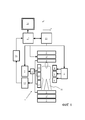
Фиг. 1 схематично показывает MR-устройство для осуществления способа изобретения;FIG. 1 schematically shows an MR device for implementing the method of the invention;
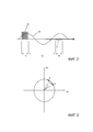
Фиг. 2 показывает диаграмму, иллюстрирующую последовательность визуализации, применяемую согласно изобретению;FIG. 2 shows a diagram illustrating a visualization sequence used according to the invention;
Фиг. 3 показывает диаграмму, схематично иллюстрирующую возможную траекторию градиентного вектора магнитного поля согласно изобретению;FIG. 3 shows a diagram schematically illustrating a possible trajectory of a magnetic field gradient vector according to the invention;
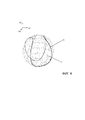
Фиг. 4 показывает диаграмму, иллюстрирующую возможные траектории градиентного вектора магнитного поля, чтобы дискретизировать трехмерный сферический объем согласно изобретению.FIG. 4 shows a diagram illustrating possible trajectories of a gradient vector of a magnetic field to discretize a three-dimensional spherical volume according to the invention.
Подробное описание вариантов осуществленияDetailed Description of Embodiments
Со ссылкой на фиг. 1, показано MR-устройство 1, которое может использоваться для осуществления способа изобретения. Устройство содержит сверхпроводящие или резистивные основные магнитные катушки 2, так что практически однородное постоянное во времени основное магнитное поле B0 создается вдоль оси Z через объем исследования. Устройство дополнительно содержит набор шиммирующих катушек 2' (первого, второго и, если применимо, третьего порядка), при этом электрический ток через отдельные шиммирующие катушки набора 2' является управляемым в целях минимизации отклонений B0 в объеме исследования.With reference to FIG. 1, an
Система формирования и обработки магнитного резонанса прикладывает последовательность RF-импульсов и переключаемых градиентов магнитного поля, чтобы инвертировать или возбуждать ядерные магнитные спины, наводить магнитный резонанс, перефокусировать магнитный резонанс, обрабатывать магнитный резонанс, пространственно и иным способом кодировать магнитный резонанс, насыщать спины и т.п., чтобы выполнять MR-визуализацию.The system for generating and processing magnetic resonance applies a sequence of RF pulses and switched magnetic field gradients to invert or excite nuclear magnetic spins, induce magnetic resonance, refocus magnetic resonance, process magnetic resonance, spatially and otherwise encode magnetic resonance, saturate spins, etc. p. to perform MR imaging.
Более конкретно, усилитель 3 градиентных импульсов прикладывает импульсы тока к выбранным из градиентных катушек 4, 5 и 6 по всему телу вдоль осей X, Y и Z объема исследования. Цифровое RF-частотное передающее устройство 7 передает RF-импульсы или импульсные пакеты, через переключатель 8 режима отправки/приема, в RF-катушку 9 для тела, чтобы передавать RF-импульсы в объем исследования. Типичная последовательность MR-визуализации состоит из пакета сегментов RF-импульсов небольшой длительности, который совместно друг с другом и со всеми применяемыми градиентами магнитного поля позволяют достигать выбранной обработки ядерного магнитного резонанса. RF-импульсы используются для того, чтобы насыщать, возбуждать резонанс, инвертировать намагничивание, перефокусировать резонанс или обрабатывать резонанс и выбирать часть тела 10, позиционированную в объеме исследования. MR-сигналы также снимаются посредством RF-катушки 9 для тела.More specifically, the
Для формирования MR-изображений ограниченных областей тела 10 посредством параллельной визуализации, набор локальных матричных RF-катушек 11, 12, 13 помещается рядом с областью, выбранной для визуализации. Матричные катушки 11, 12, 13 могут использоваться для того, чтобы принимать MR-сигналы, обусловленные посредством RF-передач из катушек для тела.To generate MR images of limited areas of the
Результирующие MR-сигналы снимаются посредством RF-катушки 9 для тела и/или посредством матричных RF-катушек 11, 12, 13 и демодулируются посредством приемного устройства 14, предпочтительно включающего в себя предусилитель (не показан). Приемное устройство 14 соединяется с RF-катушками 9, 11, 12 и 13 через переключатель 8 режима отправки/приема.The resulting MR signals are picked up by the
Хост-компьютер 15 управляет электрическим током через шиммирующие катушки 2', а также усилитель 3 градиентных импульсов и передающее устройство 7, чтобы формировать последовательность MR-визуализации согласно изобретению. Приемное устройство 14 принимает множество линий передачи MR-данных в быстрой последовательности после каждого RF-импульса возбуждения. Система 16 получения данных выполняет аналого-цифровое преобразование принимаемых сигналов и преобразует каждую линию передачи MR-данных в цифровой формат, подходящий для последующей обработки. В современных MR-устройствах, система 16 получения данных представляет собой отдельный компьютер, который специализирован на получении данных необработанных изображений.The
В конечном счете, данные цифровых необработанных изображений восстанавливаются в представление в форме изображений посредством процессора 17 восстановления, который применяет надлежащий алгоритм восстановления. MR-изображение представляет трехмерный объем. Изображение затем сохраняется в запоминающем устройстве изображений, в котором к нему может осуществляться доступ для преобразования проекций или других частей представления в форме изображений в надлежащий формат для визуализации, например, через видеомонитор 18, который предоставляет воспринимаемое человеком отображение результирующего MR-изображения.Ultimately, the digital raw image data is restored to a representation in the form of images by a
Фиг. 2 показывает схему, иллюстрирующую последовательность MR-визуализации, применяемую согласно изобретению. Сущность технологии бесшумного сканирования по принципу "резинового мяча", приспосабливаемой посредством изобретения, заключается в том, что RF-импульсы 20 возбуждения передаются одновременно с включением частотно кодированных считываемых градиентов GX, GY, GZ магнитного поля (из которых только GX показан на фиг. 2). Считываемый градиент GX магнитного поля не предназначен в качестве градиента выбора среза, что подразумевает то, что RF-импульсы 20 должны быть короткими (обычно 1-10 мкс), чтобы достигать достаточной полосы пропускания возбуждения.FIG. 2 shows a diagram illustrating the MR imaging sequence used according to the invention. The essence of the silent ball scanning technology adapted by the invention is that the
Градиент GX магнитного поля варьируется постепенно, т.е. непрерывно (например, синусоидально) в ходе этапа a), от начального значения до конечного значения, в то время как RF-импульсы 20 излучаются в присутствии градиента магнитного поля. В ходе этапа a'), постепенное варьирование градиента Gx магнитного поля продолжается, в то время как градиент GX магнитного поля варьируется от конечного значения обратно до начального значения таким образом, что временной интеграл градиента GX магнитного поля для этапов a) и a') равен нулю (что соответствует одному полному периоду колебаний синусоидального варьирования GX). На этапе b), постепенное варьирование GX продолжается, при этом GX варьируется снова от начального значения до конечного значения пока определенное число получений 21 MR-эхо-сигналов выполняется в присутствии градиента GX магнитного поля.The magnetic field gradient GX varies gradually, i.e. continuously (for example, sinusoidally) during step a), from the initial value to the final value, while the
Сферический объем в k-пространстве дискретизирован посредством повторения этапов a), a') и b) определенное число раз, при этом траектория градиентного вектора варьируется, соответственно, в зависимости от повторения. В завершение, T2*-контрастное MR-изображение восстанавливается из полученных MR-эхо-сигналов. Эхо-время соответствует длительности одного периода колебаний синусоидального варьирования GX в проиллюстрированном варианте осуществления, которая, например, может составлять в диапазоне между 10 и 500 мс.The spherical volume in k-space is discretized by repeating steps a), a ') and b) a certain number of times, while the trajectory of the gradient vector varies, respectively, depending on the repetition. Finally, the T2 * contrast MR image is reconstructed from the received MR echoes. The echo time corresponds to the duration of one oscillation period of the sinusoidal variation of GX in the illustrated embodiment, which, for example, can be in the range between 10 and 500 ms.
Базовая идея касательно изобретения поясняется ниже в двух измерениях со ссылкой на фиг. 3, показывающий координаты GX и GY градиента магнитного поля. Градиентный вектор магнитного поля (определенный посредством направления и интенсивности градиента магнитного поля) варьируется непрерывно от начальной позиции A к конечной позиции B в ходе этапа a) по множеству промежуточных позиций, в то время как RF-импульсы 20 прикладываются, как пояснено выше со ссылкой на фиг. 2. Сплошная стрелка от позиции A к позиции B представляет траекторию градиентного вектора магнитного поля в ходе этапа a). Промежуточные позиции расположены на этой траектории. На этапе a') градиентный вектор магнитного поля варьируется дополнительно вдоль круговой траектории 30. Поскольку траектория от позиции A к позиции B и дальше от позиции B обратно к позиции A центрируется на начале координат, временной интеграл вектора (GX, GY) магнитного поля по всей траектории равен нулю. Градиентный вектор магнитного поля придерживается совершенно идентичной траектории от позиции A к позиции B во второй раз на этапе b) (указываемой посредством пунктирной стрелки на фиг. 3) таким образом, что появляется последовательность MR-эхо, причем каждое MR-эхо соответствует одному из RF-импульсов 20. Эти MR-эхо-сигналы получаются вдоль "лучей" в радиальном k-пространстве (с очень небольшой кривизной) на этапе b), и MR-изображение восстанавливается из них. Лучи в радиальном k-пространстве проиллюстрированы в качестве пунктирных радиальных линий на схеме по фиг. 3. Градиент магнитного поля остается включенным при постоянной интенсивности при варьировании непрерывно относительно своего направления на всех этапах a) и b) в проиллюстрированном варианте осуществления.The basic idea of the invention is explained below in two dimensions with reference to FIG. 3, showing the coordinates GX and GY of the magnetic field gradient. The magnetic field gradient vector (determined by the direction and intensity of the magnetic field gradient) varies continuously from the initial position A to the final position B during step a) over a plurality of intermediate positions, while the
Траектория градиентного вектора магнитного поля на этапе a') может выбираться по-другому, например, для получения конкретного эхо-времени, которое определяется посредством длительности этапа a') при условии, что временной интеграл градиента для этапов a) и a') равен нулю.The trajectory of the magnetic field gradient vector in step a ') can be selected differently, for example, to obtain a specific echo time, which is determined by the duration of step a'), provided that the time integral of the gradient for steps a) and a ') is zero .
Обычно, варьирование градиента магнитного поля по полной круговой траектории, как показано на фиг. 3, может отнимать 100 мс, для времени повторения RF-импульсов в 1 мс. Это означает то, что должны получаться 100 лучей в k-пространстве. Каждый из этих лучей в k-пространстве получается через 100 мс после соответствующего RF-импульса, так что намагничивание подвергнуто T2*-затуханию. Это приводит к соответствующему T2*-контрастному MR-изображению.Typically, varying the magnetic field gradient along a full circular path, as shown in FIG. 3, can take 100 ms, for a 1 ms pulse repetition time of RF pulses. This means that 100 rays in k-space should be obtained. Each of these rays in k-space is obtained 100 ms after the corresponding RF pulse, so that the magnetization is subjected to T2 * attenuation. This results in a corresponding T2 * contrast MR image.
Фиг. 4 иллюстрирует расширение принципов изобретения до трех измерений. Круговые траектории вектора (GX, GY, GZ) градиентного магнитного поля могут выбираться в качестве меридианов 40 показанного сферического объема. После каждого кругового двойного обхода, согласно изобретению, азимутальный угол немного изменяется таким образом, что следующая круговая траектория формирует другой меридиан до тех пор, пока полный сферический объем не будет покрыт посредством соответствующих лучей в k-пространстве.FIG. 4 illustrates the extension of the principles of the invention to three dimensions. The circular paths of the gradient magnetic field vector (GX, GY, GZ) can be selected as the
Тем не менее, как уже упомянуто, может выбираться другая форма траекторий градиента магнитного поля. Другая возможная траектория представляет собой траекторию 41 теннисного мяча, также показанную на фиг. 4. Центр траектории 41 теннисного мяча также совпадает с началом системы координат градиента, так что временной интеграл градиентного вектора магнитного поля по полной траектории 41 равен нулю. Сферический объем может покрываться посредством последовательности различных траекторий теннисного мяча. Преимущество траектории 41 теннисного мяча состоит в том, что после одной полной траектории временной интеграл градиента магнитного поля (момента нулевого порядка) равен нулю, но момент первого порядка отличается между траекторией 41 теннисного мяча и траекторией вдоль меридиана 40. Это приводит к различной чувствительности к движению и диффузии. Чтобы получать диффузно-контрастное MR-изображение, например, MR-эхо-сигналы в силу этого могут получаться вдоль обеих траекторий 40 и 41, т.е. при двух различных значениях момента первого порядка траектории градиента магнитного поля.However, as already mentioned, a different shape of the trajectories of the magnetic field gradient can be selected. Another possible path is a
С использованием траектории 41 теннисного мяча, макроскопическое движение исследуемого объекта 10 вызывает фазовые эффекты в полученных MR-эхо-сигналах, варьирующихся в зависимости от траектории (при этом траектории обычно разнесены на 100 мс во времени). После дискретизации k-пространства вдоль одной траектории 41 теннисного мяча, центр k-пространства уже достаточно плотно дискретизирован, чтобы обеспечивать возможность восстановления трехмерной фазовой карты низкого разрешения. Эта фазовая карта может использоваться в качестве внутреннего навигатора, который обеспечивает коррекцию обусловленных движением разностей между последовательными траекториями теннисного мяча. В силу этого могут исключаться артефакты движения.Using the
Claims (35)
Applications Claiming Priority (3)
| Application Number | Priority Date | Filing Date | Title |
|---|---|---|---|
| EP14197679.5 | 2014-12-12 | ||
| EP14197679 | 2014-12-12 | ||
| PCT/EP2015/077994 WO2016091623A1 (en) | 2014-12-12 | 2015-11-30 | Quiet mr imaging |
Publications (3)
| Publication Number | Publication Date |
|---|---|
| RU2017124584A RU2017124584A (en) | 2019-01-15 |
| RU2017124584A3 RU2017124584A3 (en) | 2019-04-23 |
| RU2702911C2 true RU2702911C2 (en) | 2019-10-14 |
Family
ID=52231831
Family Applications (1)
| Application Number | Title | Priority Date | Filing Date |
|---|---|---|---|
| RU2017124584A RU2702911C2 (en) | 2014-12-12 | 2015-11-30 | Quiet mr-visualization |
Country Status (7)
| Country | Link |
|---|---|
| US (1) | US10379184B2 (en) |
| EP (1) | EP3230758B1 (en) |
| JP (1) | JP6666348B2 (en) |
| CN (1) | CN107110942B (en) |
| BR (1) | BR112017012208B1 (en) |
| RU (1) | RU2702911C2 (en) |
| WO (1) | WO2016091623A1 (en) |
Families Citing this family (1)
| Publication number | Priority date | Publication date | Assignee | Title |
|---|---|---|---|---|
| EP3579009A1 (en) * | 2018-06-05 | 2019-12-11 | Koninklijke Philips N.V. | Zero echo time mr imaging with water-fat separation |
Citations (4)
| Publication number | Priority date | Publication date | Assignee | Title |
|---|---|---|---|---|
| SU1732246A1 (en) * | 1990-06-07 | 1992-05-07 | Ленинградский Институт Точной Механики И Оптики | Device for magnetic field construction |
| US5570018A (en) * | 1992-01-13 | 1996-10-29 | British Technology Group Limited | Method of and apparatus for obtaining spatial NMR information |
| US5617026A (en) * | 1993-09-17 | 1997-04-01 | Hitachi Medical Corporation | Quiet magnetic resonance imaging apparatus |
| WO2013165571A1 (en) * | 2012-04-30 | 2013-11-07 | The General Hospital Corporation | System and method for quiet magnetic resonance imaging |
Family Cites Families (16)
| Publication number | Priority date | Publication date | Assignee | Title |
|---|---|---|---|---|
| US4583044A (en) * | 1984-01-09 | 1986-04-15 | University Of Utah | NMR imaging method |
| GB8914467D0 (en) * | 1989-06-23 | 1989-08-09 | Nat Res Dev | Nuclear magnetic resonance imaging methods |
| US5493224A (en) * | 1992-03-03 | 1996-02-20 | Hitachi, Ltd. | Ultra high-speed magnetic resonance imaging method and apparatus |
| US5537039A (en) * | 1995-10-10 | 1996-07-16 | General Electric Company | Virtual frequency encoding of acquired NMR image data |
| JP3525007B2 (en) * | 1996-03-28 | 2004-05-10 | 株式会社日立メディコ | Magnetic resonance imaging system |
| JP5305785B2 (en) * | 2008-08-25 | 2013-10-02 | ジーイー・メディカル・システムズ・グローバル・テクノロジー・カンパニー・エルエルシー | Magnetic resonance imaging apparatus and method for controlling magnetic resonance imaging apparatus |
| US20120082354A1 (en) * | 2009-06-24 | 2012-04-05 | Koninklijke Philips Electronics N.V. | Establishing a contour of a structure based on image information |
| DE102010041446B4 (en) | 2010-09-27 | 2013-05-23 | Siemens Aktiengesellschaft | Creation of an MR image data set with very short echo times TE |
| RU2013150082A (en) * | 2011-04-11 | 2015-05-20 | Конинклейке Филипс Н.В. | MAGNETIC RESONANCE VISUALIZATION WITH MAPING FIELD B1 |
| EP2615470A1 (en) * | 2012-01-12 | 2013-07-17 | Koninklijke Philips Electronics N.V. | MR imaging with B1 mapping |
| EP2626718A1 (en) * | 2012-02-09 | 2013-08-14 | Koninklijke Philips Electronics N.V. | MRI with motion correction using navigators acquired using a Dixon technique |
| DE102012205626B4 (en) * | 2012-04-05 | 2013-11-28 | Friedrich-Alexander-Universität Erlangen-Nürnberg | Functional MR imaging of a predetermined volume portion of the brain of a living examination subject |
| DE102013201616B3 (en) * | 2013-01-31 | 2014-07-17 | Siemens Aktiengesellschaft | TSE-based MR multilayer excitation insensitive to local B0 field variations |
| JPWO2015076082A1 (en) * | 2013-11-22 | 2017-03-16 | 株式会社日立製作所 | Magnetic resonance imaging system |
| US9594144B2 (en) * | 2014-04-23 | 2017-03-14 | General Electric Company | Low-noise magnetic resonance imaging using low harmonic pulse sequences |
| US20160066874A1 (en) * | 2014-09-10 | 2016-03-10 | The General Hospital Corporation | Attenuation correction of positron emission tomography data using magnetic resonance images depicting bone density variations |
-
2015
- 2015-11-30 EP EP15801451.4A patent/EP3230758B1/en active Active
- 2015-11-30 WO PCT/EP2015/077994 patent/WO2016091623A1/en active Application Filing
- 2015-11-30 US US15/534,021 patent/US10379184B2/en active Active
- 2015-11-30 JP JP2017531156A patent/JP6666348B2/en active Active
- 2015-11-30 RU RU2017124584A patent/RU2702911C2/en active
- 2015-11-30 BR BR112017012208-1A patent/BR112017012208B1/en active IP Right Grant
- 2015-11-30 CN CN201580073143.8A patent/CN107110942B/en active Active
Patent Citations (4)
| Publication number | Priority date | Publication date | Assignee | Title |
|---|---|---|---|---|
| SU1732246A1 (en) * | 1990-06-07 | 1992-05-07 | Ленинградский Институт Точной Механики И Оптики | Device for magnetic field construction |
| US5570018A (en) * | 1992-01-13 | 1996-10-29 | British Technology Group Limited | Method of and apparatus for obtaining spatial NMR information |
| US5617026A (en) * | 1993-09-17 | 1997-04-01 | Hitachi Medical Corporation | Quiet magnetic resonance imaging apparatus |
| WO2013165571A1 (en) * | 2012-04-30 | 2013-11-07 | The General Hospital Corporation | System and method for quiet magnetic resonance imaging |
Also Published As
| Publication number | Publication date |
|---|---|
| RU2017124584A (en) | 2019-01-15 |
| WO2016091623A1 (en) | 2016-06-16 |
| CN107110942A (en) | 2017-08-29 |
| EP3230758A1 (en) | 2017-10-18 |
| US10379184B2 (en) | 2019-08-13 |
| BR112017012208B1 (en) | 2022-07-19 |
| EP3230758B1 (en) | 2021-01-06 |
| BR112017012208A2 (en) | 2018-01-30 |
| CN107110942B (en) | 2020-06-16 |
| JP6666348B2 (en) | 2020-03-13 |
| JP2017536934A (en) | 2017-12-14 |
| RU2017124584A3 (en) | 2019-04-23 |
| US20180329008A1 (en) | 2018-11-15 |
Similar Documents
| Publication | Publication Date | Title |
|---|---|---|
| RU2523687C2 (en) | Magnetic resonance tomography using parallel signal receipt | |
| JP6356809B2 (en) | Zero echo time MR imaging with water / fat separation | |
| JP6074126B1 (en) | Zero echo time MR imaging using sampling in the center of k-space | |
| JP6416413B2 (en) | MR imaging method, MR device, and computer program | |
| EP3191862B1 (en) | Zero echo time mr imaging | |
| US9159145B2 (en) | Fast dual contrast MR imaging | |
| JP6684824B2 (en) | T2-weighted MR imaging with non-T2-weighted signal contribution removed | |
| JP2023134495A (en) | Zero echo time MR imaging with water/fat separation | |
| US11959986B2 (en) | MR imaging with spiral acquisition | |
| RU2702911C2 (en) | Quiet mr-visualization | |
| RU2785553C2 (en) | Magnetic resonance imaging with spiral data collection | |
| US11906607B2 (en) | Efficient self-refocusing zero echo time MR imaging |