RU2700952C2 - Container having improved curvilinear edge - Google Patents
Container having improved curvilinear edge Download PDFInfo
- Publication number
- RU2700952C2 RU2700952C2 RU2017135232A RU2017135232A RU2700952C2 RU 2700952 C2 RU2700952 C2 RU 2700952C2 RU 2017135232 A RU2017135232 A RU 2017135232A RU 2017135232 A RU2017135232 A RU 2017135232A RU 2700952 C2 RU2700952 C2 RU 2700952C2
- Authority
- RU
- Russia
- Prior art keywords
- ablation
- curved edge
- preform
- thickness
- container
- Prior art date
Links
Images
Classifications
-
- B—PERFORMING OPERATIONS; TRANSPORTING
- B65—CONVEYING; PACKING; STORING; HANDLING THIN OR FILAMENTARY MATERIAL
- B65D—CONTAINERS FOR STORAGE OR TRANSPORT OF ARTICLES OR MATERIALS, e.g. BAGS, BARRELS, BOTTLES, BOXES, CANS, CARTONS, CRATES, DRUMS, JARS, TANKS, HOPPERS, FORWARDING CONTAINERS; ACCESSORIES, CLOSURES, OR FITTINGS THEREFOR; PACKAGING ELEMENTS; PACKAGES
- B65D85/00—Containers, packaging elements or packages, specially adapted for particular articles or materials
- B65D85/07—Containers, packaging elements or packages, specially adapted for particular articles or materials for compressible or flexible articles
- B65D85/08—Containers, packaging elements or packages, specially adapted for particular articles or materials for compressible or flexible articles rod-shaped or tubular
- B65D85/10—Containers, packaging elements or packages, specially adapted for particular articles or materials for compressible or flexible articles rod-shaped or tubular for cigarettes
- B65D85/1036—Containers formed by erecting a rigid or semi-rigid blank
- B65D85/1045—Containers formed by erecting a rigid or semi-rigid blank having a cap-like lid hinged to an edge
- B65D85/1048—Containers formed by erecting a rigid or semi-rigid blank having a cap-like lid hinged to an edge characterized by the shape of the container
- B65D85/10484—Containers formed by erecting a rigid or semi-rigid blank having a cap-like lid hinged to an edge characterized by the shape of the container having rounded corners
-
- A—HUMAN NECESSITIES
- A24—TOBACCO; CIGARS; CIGARETTES; SIMULATED SMOKING DEVICES; SMOKERS' REQUISITES
- A24F—SMOKERS' REQUISITES; MATCH BOXES; SIMULATED SMOKING DEVICES
- A24F15/00—Receptacles or boxes specially adapted for cigars, cigarettes, simulated smoking devices or cigarettes therefor
- A24F15/12—Receptacles or boxes specially adapted for cigars, cigarettes, simulated smoking devices or cigarettes therefor for pocket use
- A24F15/18—Receptacles or boxes specially adapted for cigars, cigarettes, simulated smoking devices or cigarettes therefor for pocket use combined with other objects
-
- B—PERFORMING OPERATIONS; TRANSPORTING
- B65—CONVEYING; PACKING; STORING; HANDLING THIN OR FILAMENTARY MATERIAL
- B65D—CONTAINERS FOR STORAGE OR TRANSPORT OF ARTICLES OR MATERIALS, e.g. BAGS, BARRELS, BOTTLES, BOXES, CANS, CARTONS, CRATES, DRUMS, JARS, TANKS, HOPPERS, FORWARDING CONTAINERS; ACCESSORIES, CLOSURES, OR FITTINGS THEREFOR; PACKAGING ELEMENTS; PACKAGES
- B65D5/00—Rigid or semi-rigid containers of polygonal cross-section, e.g. boxes, cartons or trays, formed by folding or erecting one or more blanks made of paper
- B65D5/42—Details of containers or of foldable or erectable container blanks
- B65D5/4266—Folding lines, score lines, crease lines
-
- B—PERFORMING OPERATIONS; TRANSPORTING
- B65—CONVEYING; PACKING; STORING; HANDLING THIN OR FILAMENTARY MATERIAL
- B65D—CONTAINERS FOR STORAGE OR TRANSPORT OF ARTICLES OR MATERIALS, e.g. BAGS, BARRELS, BOTTLES, BOXES, CANS, CARTONS, CRATES, DRUMS, JARS, TANKS, HOPPERS, FORWARDING CONTAINERS; ACCESSORIES, CLOSURES, OR FITTINGS THEREFOR; PACKAGING ELEMENTS; PACKAGES
- B65D5/00—Rigid or semi-rigid containers of polygonal cross-section, e.g. boxes, cartons or trays, formed by folding or erecting one or more blanks made of paper
- B65D5/42—Details of containers or of foldable or erectable container blanks
- B65D5/64—Lids
- B65D5/66—Hinged lids
- B65D5/6602—Hinged lids formed by folding one or more extensions hinged to the upper edge of a tubular container body
-
- B—PERFORMING OPERATIONS; TRANSPORTING
- B65—CONVEYING; PACKING; STORING; HANDLING THIN OR FILAMENTARY MATERIAL
- B65D—CONTAINERS FOR STORAGE OR TRANSPORT OF ARTICLES OR MATERIALS, e.g. BAGS, BARRELS, BOTTLES, BOXES, CANS, CARTONS, CRATES, DRUMS, JARS, TANKS, HOPPERS, FORWARDING CONTAINERS; ACCESSORIES, CLOSURES, OR FITTINGS THEREFOR; PACKAGING ELEMENTS; PACKAGES
- B65D85/00—Containers, packaging elements or packages, specially adapted for particular articles or materials
- B65D85/07—Containers, packaging elements or packages, specially adapted for particular articles or materials for compressible or flexible articles
- B65D85/08—Containers, packaging elements or packages, specially adapted for particular articles or materials for compressible or flexible articles rod-shaped or tubular
- B65D85/10—Containers, packaging elements or packages, specially adapted for particular articles or materials for compressible or flexible articles rod-shaped or tubular for cigarettes
- B65D85/1036—Containers formed by erecting a rigid or semi-rigid blank
- B65D85/1045—Containers formed by erecting a rigid or semi-rigid blank having a cap-like lid hinged to an edge
Abstract
Description
Настоящее изобретение относится к таре для потребительских товаров и к слоистой заготовке на основе целлюлозных волокон для образования такой тары, которая находит конкретное применение в хранении удлиненных потребительских товаров, таких как курительные изделия (например, сигареты).The present invention relates to a container for consumer goods and to a layered blank based on cellulose fibers for the formation of such containers, which finds particular application in the storage of elongated consumer goods, such as smoking articles (for example, cigarettes).
Курительные изделия, такие как сигареты и сигары, обычно предлагаются в мягких пачках или твердых пачках, таких как коробки с откидной крышкой или коробки с шарнирной крышкой. Они обычно содержат часть в виде коробки, имеющую переднюю стенку коробки, заднюю стенку коробки, боковые стенки коробки и основание коробки. Они также обычно содержат часть в виде крышки с передней стенкой крышки, задней стенкой крышки, боковыми стенками крышки и верхней стороной крышки. Часть в виде крышки обычно шарнирно соединена с частью в виде коробки вдоль линии шарнира, проходящей поперек задней стенки тары. Линия шарнира обычно предусмотрена в виде предварительно сложенной линии, линии рилевки или линии биговки.Smoking articles, such as cigarettes and cigars, are usually offered in soft packs or hard packs, such as hinged lid boxes or hinged lid boxes. They usually comprise a box-shaped part having a box front wall, a box back wall, box side walls and a box base. They also typically comprise a lid part with a lid front wall, a lid back wall, lid side walls and a lid top. The lid part is usually pivotally connected to the box part along the hinge line extending across the rear wall of the container. The hinge line is usually provided as a pre-folded line, a groove line or a creasing line.
Тару в виде твердых пачек или по меньшей мере ее части обычно получают из слоистой заготовки, содержащей несколько панелей. Для сборки тары одна такая заготовка складывается таким образом, что панели заготовки могут образовывать стенки тары.A pack in the form of solid packs, or at least part thereof, is usually obtained from a laminated preform containing several panels. For packaging, one such blank is folded so that the blank panels can form the walls of the container.
В случае твердых пачек известно, что некоторые кромки коробки и крышки закругляют или скашивают для придания таре отличительного внешнего вида. Ранее это обычно осуществлялось путем создания линий рилевки или линий биговки в заготовке в областях, образующих кромки тары. Эти линии позволяют заготовке складываться таким образом, что кромка изгибается не просто по единственной линии, но вместо этого либо постепенно изгибается между двумя смежными стенками (в случае закругленной кромки), либо изгибается в двух или более отдельных местах между смежными стенками (в случае скошенной кромки).In the case of solid packs, it is known that some edges of the box and lid are rounded or chamfered to give the container a distinctive appearance. Previously, this was usually done by creating groove lines or creasing lines in the workpiece in the areas forming the edges of the container. These lines allow the workpiece to be folded in such a way that the edge bends not just in a single line, but instead either gradually bends between two adjacent walls (in the case of a rounded edge), or bends in two or more separate places between adjacent walls (in the case of a beveled edge )
Тем не менее, такие линии биговки или рилевки могут повысить сложность процесса изготовления. Кроме этого, в некоторых случаях визуальное и тактильное восприятие тары может быть нарушено тем, что внешняя поверхность не полностью гладкая и может содержать складки или волнообразные неровности, проходящие от места рилевки.However, such scoring or scoring lines can increase the complexity of the manufacturing process. In addition, in some cases, the visual and tactile perception of the container may be impaired by the fact that the outer surface is not completely smooth and may contain folds or wave-like irregularities extending from the groove.
Таким образом, было бы желательным предоставление тары для потребительских товаров, имеющей одну или несколько криволинейных кромок, которые имеют улучшенный вид. Было бы также желательно предоставить тару для потребительских товаров с частью в виде криволинейной кромки, которая была бы более прочной, а также была бы более простой в производстве. Дополнительно, было бы также желательно предоставить заготовку для изготовления тары для потребительских товаров, которая упростила бы производственный процесс и процесс сборки и сделала бы их более гибкими.Thus, it would be desirable to provide containers for consumer goods having one or more curved edges that have an improved appearance. It would also be desirable to provide containers for consumer goods with a part in the form of a curved edge, which would be more durable and would also be easier to manufacture. Additionally, it would also be desirable to provide a blank for the manufacture of containers for consumer goods, which would simplify the production process and the assembly process and make them more flexible.
Согласно первому аспекту настоящего изобретения предусмотрена тара для потребительских изделий, при этом тара по меньшей мере частично образована из слоистой заготовки на основе целлюлозного волокна, имеющей толщину (T), при этом слоистая заготовка образует часть тары, которая содержит по меньшей мере первую плоскую стенку и вторую плоскую стенку, которые соединены друг с другом посредством части в виде криволинейной кромки; при этом часть в виде криволинейной кромки имеет внутреннюю поверхность и внешнюю поверхность, и внутренняя поверхность части в виде криволинейной кромки образует область (А) абляции, при этом область абляции имеет длину (L) в продольном направлении части в виде криволинейной кромки и ширину (W), которая проходит поперек части в виде криволинейной кромки; при этом область абляции содержит две или более линий абляции, проходящих по существу в продольном направлении части в виде криволинейной кромки, при этом каждая линия абляции имеет минимальную остаточную толщину (RT), составляющую по меньшей мере приблизительно 20 процентов, предпочтительно по меньшей мере приблизительно 25, более предпочтительно по меньшей мере приблизительно 30 процентов от толщины (T) заготовки. Дополнительно или в качестве альтернативы, каждая из линий абляции предпочтительно имеет остаточную толщину, составляющую менее приблизительно 65 процентов, более предпочтительно менее приблизительно 60 процентов и еще более предпочтительно менее приблизительно 55 процентов от толщины (Т) заготовки.According to a first aspect of the present invention, there is provided a container for consumer products, wherein the container is at least partially formed from a laminated preform based on cellulose fiber having a thickness (T), wherein the layered preform forms a part of the container that contains at least a first flat wall and a second flat wall, which are connected to each other by means of a part in the form of a curved edge; the part in the form of a curved edge has an inner surface and an external surface, and the inner surface of the part in the form of a curved edge forms an ablation region (A), while the ablation region has a length (L) in the longitudinal direction of the part in the form of a curved edge and width (W ), which runs across the part in the form of a curved edge; wherein the ablation region contains two or more ablation lines extending essentially in the longitudinal direction of the part in the form of a curved edge, with each ablation line having a minimum residual thickness (RT) of at least about 20 percent, preferably at least about 25 , more preferably at least about 30 percent of the thickness (T) of the preform. Additionally or alternatively, each of the ablation lines preferably has a residual thickness of less than about 65 percent, more preferably less than about 60 percent, and even more preferably less than about 55 percent of the thickness (T) of the preform.
Авторы настоящего изобретения также установили, что для получения части в виде криволинейной кромки заявленный диапазон остаточной толщины комбинируется с зазором по меньшей мере приблизительно 0,2 миллиметра между нижними точками двух смежных линий абляции. Предпочтительно, зазор между нижними точками двух смежных линий абляции составляет по меньшей мере приблизительно 0,4 миллиметра и еще более предпочтительно по меньшей мере приблизительно 0,6 миллиметра. Дополнительно или альтернативно, зазор между нижними точками двух смежных линий абляции составляет менее приблизительно 1,6 миллиметра, более предпочтительно менее приблизительно 1,3 миллиметра и еще более предпочтительно менее приблизительно 1,0 миллиметра.The inventors have also found that to obtain a curved edge part, the claimed residual thickness range is combined with a gap of at least about 0.2 millimeters between the lower points of two adjacent ablation lines. Preferably, the gap between the lower points of two adjacent ablation lines is at least about 0.4 millimeters, and even more preferably at least about 0.6 millimeters. Additionally or alternatively, the gap between the lower points of two adjacent ablation lines is less than about 1.6 millimeters, more preferably less than about 1.3 millimeters, and even more preferably less than about 1.0 millimeters.
Согласно второму аспекту настоящего изобретения предусмотрена слоистая заготовка для образования тары для потребительских изделий, при этом заготовка имеет толщину (Т) и образует часть тары, которая содержит по меньшей мере первую плоскую стенку и вторую плоскую стенку, которые соединены друг с другом посредством части в виде криволинейной кромки; при этом часть в виде криволинейной кромки имеет внутреннюю поверхность и внешнюю поверхность, и внутренняя поверхность части в виде криволинейной кромки образует область (А) абляции, при этом область абляции имеет длину (L) в продольном направлении части в виде криволинейной кромки и ширину (W), которая проходит поперек части в виде криволинейной кромки; при этом область абляции содержит две или более линий абляции, проходящих по существу в продольном направлении части в виде криволинейной кромки, при этом каждая линия абляции имеет минимальную остаточную толщину (RT), составляющую по меньшей мере приблизительно 20 процентов, предпочтительно по меньшей мере приблизительно 25, более предпочтительно по меньшей мере приблизительно 30 процентов от толщины (T) заготовки. Дополнительно или в качестве альтернативы, каждая из линий абляции предпочтительно имеет остаточную толщину, составляющую менее приблизительно 65 процентов, более предпочтительно менее приблизительно 60 процентов и еще более предпочтительно менее приблизительно 55 процентов от толщины (Т) заготовки.According to a second aspect of the present invention, there is provided a laminate preform for forming containers for consumer products, wherein the preform has a thickness (T) and forms a part of the container that comprises at least a first flat wall and a second flat wall, which are connected to each other via a part in the form curved edges; the part in the form of a curved edge has an inner surface and an external surface, and the inner surface of the part in the form of a curved edge forms an ablation region (A), while the ablation region has a length (L) in the longitudinal direction of the part in the form of a curved edge and width (W ), which runs across the part in the form of a curved edge; wherein the ablation region contains two or more ablation lines extending essentially in the longitudinal direction of the part in the form of a curved edge, with each ablation line having a minimum residual thickness (RT) of at least about 20 percent, preferably at least about 25 , more preferably at least about 30 percent of the thickness (T) of the preform. Additionally or alternatively, each of the ablation lines preferably has a residual thickness of less than about 65 percent, more preferably less than about 60 percent, and even more preferably less than about 55 percent of the thickness (T) of the preform.
Авторы настоящего изобретения также установили, что для получения части в виде криволинейной кромки заявленный диапазон остаточной толщины комбинируется с зазором по меньшей мере приблизительно 0,2 миллиметра между нижними точками двух смежных линий абляции. Предпочтительно, зазор между нижними точками двух смежных линий абляции составляет по меньшей мере приблизительно 0,4 миллиметра и еще более предпочтительно по меньшей мере приблизительно 0,6 миллиметра. Дополнительно или альтернативно, зазор между нижними точками двух смежных линий абляции составляет менее приблизительно 1,6 миллиметра, более предпочтительно менее приблизительно 1,3 миллиметра и еще более предпочтительно менее приблизительно 1,0 миллиметра.The inventors have also found that to obtain a curved edge part, the claimed residual thickness range is combined with a gap of at least about 0.2 millimeters between the lower points of two adjacent ablation lines. Preferably, the gap between the lower points of two adjacent ablation lines is at least about 0.4 millimeters, and even more preferably at least about 0.6 millimeters. Additionally or alternatively, the gap between the lower points of two adjacent ablation lines is less than about 1.6 millimeters, more preferably less than about 1.3 millimeters, and even more preferably less than about 1.0 millimeters.
Следует иметь в виду, что любые признаки, описанные в отношении одного аспекта настоящего изобретения, в равной степени применимы к любому другому аспекту настоящего изобретения.It should be borne in mind that any features described in relation to one aspect of the present invention are equally applicable to any other aspect of the present invention.
В отличие от существующих видов тары, в которых используются механические линии рилевки для образования части в виде криволинейной кромки тары, настоящее изобретение включает удаление материала с особых мест в части заготовки, которая образует часть в виде криволинейной кромки тары. Предоставление областей абляции, включающих линии абляции (например, образованные посредством лазерной абляции) для образования части в виде криволинейной кромки тары, преимущественным образом уменьшает усилие, необходимое для складывания заготовки по части в виде криволинейной кромки. Кроме того, закругленная кромка тары эффективно приближается к теоретической эталонной закругленной форме при сравнительно небольшом количестве линий биговки. Таким образом, одновременно может обеспечиваться возможность лучшего сохранения прочности тары в местах закругленных кромок.Unlike existing types of containers that use mechanical grooving lines to form a part in the form of a curved edge of the container, the present invention includes removing material from special places in the part of the workpiece, which forms a part in the form of a curved edge of the container. Providing ablation areas, including ablation lines (for example, formed by laser ablation) to form a part in the form of a curved edge of the container, advantageously reduces the force required to fold the workpiece in part in the form of a curved edge. In addition, the rounded edge of the container effectively approaches the theoretical reference rounded shape with a relatively small number of scoring lines. Thus, at the same time, it may be possible to better maintain the strength of the container in places of rounded edges.
Это может обеспечить традиционное образование тары из одной такой заготовки посредством традиционной упаковочной машины. Дополнительно, поскольку внешняя поверхность заготовки не подвергается воздействию процесса абляции, получающаяся в результате внешняя поверхность тары не имеет локализованных складок или волнообразных неровностей в месте линии абляции (как было бы в случае с механическими линиями рилевки).This can provide the traditional formation of containers from one such preform by means of a traditional packaging machine. Additionally, since the outer surface of the workpiece is not exposed to the ablation process, the resulting outer surface of the container does not have localized folds or wave-like irregularities in the place of the ablation line (as would be the case with mechanical grooving lines).
Соответственно, изгибание заготовки согласно настоящему изобретению при образовании части в виде криволинейной кромки тары упрощено и приводит в результате к образованию внешней поверхности тары, имеющей кривизну, которая является более плавной и гладкой, при визуальном и тактильном восприятии части пользователем.Accordingly, the bending of the preform according to the present invention when forming a part in the form of a curved edge of the container is simplified and results in the formation of an outer surface of the container having a curvature that is smoother and smoother when the user visually and tactually perceives the part.
Заготовка согласно настоящему изобретению может быть преимущественно изготовлена посредством точного удаления материала с части в виде криволинейной кромки с помощью линейного инструмента для абляции (например, лазера или лезвия). Лазер представляет собой особо предпочтительный инструмент для абляции, поскольку он является неинвазивным и возможно его цифровое программирование для повышения гибкости конструкции. В частности, использование лазера в качестве инструмента для абляции обеспечивает возможность получения широкого спектра профилей абляции и конфигураций при минимальной необходимости в регулировании лазерного инструмента. В результате многократных проходов инструмента для абляции над заданной частью заготовки происходит удаление более значительной процентной доли материала, находящегося в области уменьшенной остаточной толщины. Таким образом, процесс изготовления может быть упрощен. Лазерная абляция может быть выполнена с использованием любого подходящего оборудования, предпочтительно лазера на диоксиде углерода мощностью 1000 Ватт, такого как коммерчески доступный от компании DIAMOND, например, E-1000. Абляция может быть выполнена в направлении обработки слоистой заготовки или в поперечном направлении. Лазерная абляция может быть выполнена с использованием любого подходящего оборудования, предпочтительно лазера на диоксиде углерода мощностью 1000 Ватт, такого как коммерчески доступный от компании DIAMOND, например, E-1000. Абляция может быть выполнена в направлении обработки слоистой заготовки или в поперечном направлении.The preform according to the present invention can be advantageously made by accurately removing material from a curved edge portion using a linear ablation tool (e.g., laser or blade). The laser is a particularly preferred ablation tool because it is non-invasive and can be digitally programmed to increase design flexibility. In particular, the use of a laser as an ablation tool makes it possible to obtain a wide range of ablation profiles and configurations with minimal need for adjustment of the laser tool. As a result of multiple passes of the ablation tool over a given part of the workpiece, a larger percentage of the material located in the region of reduced residual thickness is removed. Thus, the manufacturing process can be simplified. Laser ablation can be performed using any suitable equipment, preferably a 1000 W carbon dioxide laser, such as commercially available from DIAMOND, for example, E-1000. Ablation can be performed in the direction of processing the layered workpiece or in the transverse direction. Laser ablation can be performed using any suitable equipment, preferably a 1000 W carbon dioxide laser, such as commercially available from DIAMOND, for example, E-1000. Ablation can be performed in the direction of processing the layered workpiece or in the transverse direction.
Тара, изготовленная из слоистой заготовки согласно настоящему изобретению, может быть получена без этапа предварительного изгибания, который обычно требуется при традиционных способах получения скругленных углов, например конгревном тиснении.A container made from a laminate preform according to the present invention can be obtained without the preliminary bending step, which is usually required with traditional methods for producing rounded corners, for example, stamping.
Термин «часть в виде кромки» в контексте данного документа относится к части заготовки, образующей кромку между двумя смежными стенками тары. Часть в виде криволинейной кромки является частью заготовки, которая образует кромку тары, находящуюся между первой плоской стенкой и второй плоской стенкой.The term “edge portion” in the context of this document refers to a portion of a workpiece forming an edge between two adjacent container walls. The part in the form of a curved edge is part of the workpiece, which forms the edge of the container, located between the first flat wall and the second flat wall.
Термин «часть в виде криволинейной кромки» в контексте данного документа относится к части в виде кромки тары, имеющей дугообразную форму, как видно в поперечном сечении. Термином «дугообразный» обозначена любая непрямая линия, включая дугу окружности, дугу параболы, дугу гиперболы, дугу эллипса и т. п. Часть в виде криволинейной кромки может быть измерена с помощью визуального осмотра одним или несколькими лицами, проводящими испытание, или измерения посредством микроскопа, за которым следует статистический анализ, например, с использованием микроскопа NIKON SMZ800 на внешней поверхности слоистой заготовки. X-Y-координаты могут быть записаны на мелкой расчетной сетке (10 точек контура) для каждого образца. X-Y-координаты устройства записи могут использоваться для линейной сплайн-интерполяции, и профиль получившейся в результате первой производной может быть захвачен. Постоянно меняющаяся или прыгающая первая производная отображает образец части в виде криволинейной кромки.The term "curved edge portion" in the context of this document refers to a portion in the form of an edge of a container having an arched shape, as seen in cross section. The term “curved” means any indirect line, including a circular arc, a parabola arc, a hyperbola arc, an ellipse arc, etc. A part in the form of a curved edge can be measured by visual inspection by one or more persons conducting the test, or by measurement using a microscope followed by statistical analysis, for example, using a NIKON SMZ800 microscope on the outer surface of a layered workpiece. X-Y coordinates can be written on a fine grid (10 contour points) for each sample. The X-Y coordinates of the recorder can be used for linear spline interpolation, and the profile of the resulting first derivative can be captured. A constantly changing or jumping first derivative displays a sample of the part in the form of a curved edge.
«Слоистая заготовка на основе целлюлозного волокна» в контексте данного документа относится к слоистой заготовке, содержащей по меньшей мере 50 процентов по весу целлюлозных волокон, исходя из общего содержания волокон в слоистой заготовке. Слоистая заготовка на основе целлюлозного волокна согласно настоящему изобретению может содержать другие типы волокон, например полимерные волокна.A “cellulosic fiber-based laminate preform” as used herein refers to a laminate preform containing at least 50 percent by weight of cellulosic fibers based on the total fiber content of the laminate preform. The cellulosic fiber laminate preform of the present invention may contain other types of fibers, for example polymer fibers.
Термин «внутренняя поверхность» в контексте данного описания относится к стороне части заготовки, которая в случае собранной тары обращена внутрь тары, например, в направлении потребительских товаров, когда тара закрыта. Таким образом, внутренняя поверхность непосредственно не видна потребителю, когда тара закрыта. Термин «внешняя поверхность» в контексте данного описания относится к стороне части заготовки, которая в случае собранной тары обращена в направлении наружу от тары.The term "inner surface" in the context of this description refers to the side of the part of the workpiece, which in the case of assembled containers facing the inside of the container, for example, in the direction of consumer goods, when the container is closed. Thus, the inner surface is not directly visible to the consumer when the container is closed. The term "outer surface" in the context of this description refers to the side of the part of the workpiece, which in the case of assembled containers facing outward from the container.
Термин «область абляции» в контексте данного документа относится к минимальной области заготовки, которая заключает в себе все линии абляции на части заготовки, которая образует часть в виде криволинейной кромки тары.The term "ablation region" in the context of this document refers to the minimum area of the workpiece, which encompasses all the lines of ablation on the part of the workpiece, which forms part in the form of a curved edge of the container.
Термин «линия абляции» в контексте данного документа относится к линии вдоль внутренней поверхности части в виде кромки, из которой был аблирован материал (например, удален посредством лазерного луча или лезвия). Соответственно, остаточная толщина линии абляции меньше, чем толщина (Т) слоистой заготовки. Предпочтительно, линию абляции выполняют в виде канавки в заготовке. Она может быть образована с помощью линейного инструмента для абляции, такого как лазер или лезвие.The term "ablation line" in the context of this document refers to a line along the inner surface of the part in the form of the edge from which the material was ablated (for example, removed by means of a laser beam or blade). Accordingly, the residual thickness of the ablation line is less than the thickness (T) of the laminate preform. Preferably, the ablation line is in the form of a groove in the workpiece. It can be formed using a linear ablation tool, such as a laser or a blade.
«Толщина» (T) заготовки представляет собой толщину заготовки после ее изготовления, но перед образованием на заготовке каких-либо линий абляции или линий рилевки. То есть, толщина (T) заготовки представляет собой толщину в любой области заготовки, не содержащей линию абляции или линию рилевки.The “thickness” (T) of the workpiece is the thickness of the workpiece after its manufacture, but before the formation of any ablation lines or groove lines on the workpiece. That is, the thickness (T) of the preform is the thickness in any area of the preform not containing an ablation line or a groove line.
Термин «остаточная толщина» в контексте данного документа относится к минимальному расстоянию, измеренному между двумя противоположными поверхностями слоистой заготовки или стенки тары, образованной из заготовки. На практике расстояние в заданном местоположении измеряют вдоль направления, локально перпендикулярного противоположным поверхностям. Остаточная толщина линии абляции может варьироваться по ширине линии абляции (например, V-образной, U-образной канавок).The term "residual thickness" in the context of this document refers to the minimum distance measured between two opposite surfaces of a laminated preform or a container wall formed from a preform. In practice, a distance at a given location is measured along a direction locally perpendicular to opposing surfaces. The residual thickness of the ablation line may vary across the width of the ablation line (e.g., V-shaped, U-shaped grooves).
Термин «минимальная остаточная толщина» в контексте данного документа относится к наименьшему значению «остаточной толщины», измеренной в линии абляции в заданном месте.The term "minimum residual thickness" in the context of this document refers to the smallest value of "residual thickness" measured in the ablation line at a given location.
Остаточная толщина каждой линии абляции может быть определена посредством использования оптического профилометра для 2D бесконтактной поверхностной метрологии, такого как профиль MicroSpy (RTM) (коммерчески доступный от Fries Research & Technology GmbH, г. Бергиш-Гладбах, Германия). Предпочтительно, несколько точек минимальной остаточной толщины измеряются по длине линии абляции, при этом точки измерения равномерно распределены по длине одной линии абляции, и вычисляется среднее арифметическое.The residual thickness of each ablation line can be determined using an optical profilometer for 2D non-contact surface metrology, such as a MicroSpy profile (RTM) (commercially available from Fries Research & Technology GmbH, Bergisch Gladbach, Germany). Preferably, several points of minimum residual thickness are measured along the length of the ablation line, wherein the measurement points are evenly distributed along the length of one ablation line, and the arithmetic mean is calculated.
Еще более предпочтительно, для получения «минимальной остаточной толщины» согласно настоящему изобретению выполняются пять измерений, равномерно распределенных по длине линии абляции, а затем вычисляется среднее арифметическое.Even more preferably, to obtain a “minimum residual thickness” according to the present invention, five measurements are taken uniformly distributed along the length of the ablation line, and then the arithmetic average is calculated.
Например, если длина линии абляции составляет 80 миллиметров, остаточная толщина измеряется на обоих концах линии абляции и в трех дополнительных точках, расположенных на расстоянии 20 миллиметров, сорок миллиметров и шестьдесят миллиметров соответственно от одного конца линии абляции, предпочтительно от нижнего конца линии абляции.For example, if the length of the ablation line is 80 millimeters, the residual thickness is measured at both ends of the ablation line and at three additional points located at a distance of 20 millimeters, forty millimeters and sixty millimeters respectively from one end of the ablation line, preferably from the lower end of the ablation line.
Термин «зазор» в контексте данного документа относится к расстоянию между нижними точками двух смежных линий абляции.The term “clearance” as used herein refers to the distance between the bottom points of two adjacent ablation lines.
Предпочтительно, несколько точек зазора измерены по длине пары параллельных линий абляции, при этом точки измерения равномерно распределены по длине параллельных частей линий абляции, и вычисляется среднее арифметическое.Preferably, several clearance points are measured along the length of the pair of parallel ablation lines, wherein the measurement points are evenly distributed along the length of the parallel parts of the ablation lines, and the arithmetic mean is calculated.
Еще более предпочтительно, для получения «зазора» согласно настоящему изобретению выполняются пять измерений, равномерно распределенных по длине параллельных частей двух смежных линий абляции, а затем вычисляется среднее арифметическое.Even more preferably, to obtain a “gap” according to the present invention, five measurements are taken uniformly distributed along the length of the parallel parts of two adjacent ablation lines, and then the arithmetic average is calculated.
Например, если длина параллельной части двух смежных линий абляции составляет 80 миллиметров соответственно, зазор измеряется на обоих концах и в трех дополнительных точках, расположенных на расстоянии 20 миллиметров, сорок миллиметров и шестьдесят миллиметров соответственно от одного конца параллельной части, предпочтительно от нижнего конца линии абляции.For example, if the length of the parallel part of two adjacent ablation lines is 80 millimeters, respectively, the gap is measured at both ends and at three additional points located at a distance of 20 millimeters, forty millimeters and sixty millimeters respectively from one end of the parallel part, preferably from the lower end of the ablation line .
Термин «остаточная жесткость» используется для описания жесткости существующей слоистой заготовки, измеряемой на минимальной остаточной толщине одной заданной линии абляции и вычисляется с использованием жесткости в направлении изгиба слоистой заготовки, умноженной на процентное отношение остаточной толщины. Например, если жесткость в направлении изгиба неаблированной слоистой заготовки составляет 100 миллиньютон, и минимальная остаточная толщина составляет тридцать процентов, следовательно остаточная жесткость в направлении изгиба составляет 100 миллиньютон, умноженных на тридцать процентов, и составляет 30 миллиньютон. Жесткость слоистой заготовки может быть измерена согласно ISO 2493, 15 градусов, например, путем взятия образца материала заготовки из части заготовки, которая не является согнутой или аблированной (образец может быть напечатан или иным образом покрыт, если он в готовой форме).The term “residual stiffness” is used to describe the stiffness of an existing laminate preform measured at the minimum residual thickness of a given ablation line and is calculated using stiffness in the bending direction of the laminate preform multiplied by the percentage of residual thickness. For example, if the stiffness in the bending direction of the unablated laminate is 100 millinewtons and the minimum residual thickness is thirty percent, then the residual stiffness in the bending direction is 100 millinewtons, multiplied by thirty percent, and is 30 millinewtons. The stiffness of a layered workpiece can be measured according to ISO 2493, 15 degrees, for example, by taking a sample of the workpiece material from a part of the workpiece that is not bent or ablated (the sample can be printed or otherwise coated if it is in finished form).
Осуществляется испытание и выдерживание при температуре в 23 градуса по Цельсию, 50% относительной влажности в соответствии с ISO 187 через две недели после абляции.Testing and curing is carried out at a temperature of 23 degrees Celsius, 50% relative humidity in accordance with ISO 187 two weeks after ablation.
В контексте данного документа термины «передний», «задний», «верхний», «нижний», «верх», «низ» и «боковой» относятся к относительным положениям частей тары согласно настоящему изобретению и ее компонентов, когда тара находится в вертикальном положении с отверстием для доступа в верхней части тары. В частности, когда тара представляет собой тару с шарнирной крышкой, это означает, что тара находится в вертикальном положении с крышкой в закрытом положении и линией шарнира в задней части тары. При описании тары согласно настоящему изобретению эти термины используются независимо от ориентации описываемой тары.In the context of this document, the terms "front", "rear", "upper", "lower", "top", "bottom" and "side" refer to the relative positions of the parts of the packaging according to the present invention and its components when the packaging is vertical position with a hole for access at the top of the container. In particular, when the container is a container with a hinged lid, this means that the container is in an upright position with the lid in the closed position and the hinge line in the back of the container. When describing containers according to the present invention, these terms are used regardless of the orientation of the described containers.
Тара согласно настоящему изобретению по меньшей мере частично образована из слоистой заготовки, имеющей заданную толщину (T). Заготовка образует часть тары, которая содержит по меньшей мере первую плоскую стенку и вторую плоскую стенку, соединенные друг с другом посредством части в виде криволинейной кромки. Внутренняя поверхность части в виде криволинейной кромки образует область абляции, которая имеет длину, проходящую в продольном направлении части в виде криволинейной кромки, и ширину, которая проходит поперек части в виде криволинейной кромки. Область абляции содержит две или более линий абляции, проходящие по существу в продольном направлении части в виде криволинейной кромки.A container according to the present invention is at least partially formed from a layered preform having a predetermined thickness (T). The preform forms a part of the container, which contains at least a first flat wall and a second flat wall, connected to each other by means of a part in the form of a curved edge. The inner surface of the part in the form of a curved edge forms an ablation region that has a length extending in the longitudinal direction of the part in the form of a curved edge and a width that extends across the part in the form of a curved edge. The ablation region contains two or more ablation lines extending essentially in the longitudinal direction of the part in the form of a curved edge.
Предпочтительно, толщина (T) слоистой заготовки составляет от приблизительно 300 микрометров до приблизительно 360 микрометров. Более предпочтительно, толщина (T) слоистой заготовки составляет от приблизительно 330 микрометров до приблизительно 350 микрометров. Толщина (T) слоистой заготовки может быть измерена согласно ISO 534:2011.Preferably, the thickness (T) of the laminate preform is from about 300 micrometers to about 360 micrometers. More preferably, the thickness (T) of the laminate preform is from about 330 micrometers to about 350 micrometers. The thickness (T) of the laminate preform can be measured according to ISO 534: 2011.
Область абляции может содержать любое подходящее количество линий абляции для образования части в виде криволинейной кромки. Например, в некоторых предпочтительных вариантах осуществления область абляции содержит по меньшей мере четыре линии абляции в любом заданном продольном положении на части в виде криволинейной кромки. Если в любом заданном продольном положении на части в виде криволинейной кромки предусмотрено менее четырех линий абляции, может стать сложным получение плавной кривизны, которая приближается к теоретическому криволинейному профилю, без большого уменьшения ширины области абляции и, следовательно, части в виде криволинейной кромки.The ablation region may contain any suitable number of ablation lines to form a portion in the form of a curved edge. For example, in some preferred embodiments, the ablation region comprises at least four ablation lines in any predetermined longitudinal position into parts in the form of a curved edge. If in any given longitudinal position on the part in the form of a curved edge less than four ablation lines are provided, it can become difficult to obtain a smooth curvature that approaches the theoretical curved profile without a large reduction in the width of the ablation region and, therefore, the part in the form of a curved edge.
Слоистая заготовка предпочтительно имеет базовый вес от приблизительно 150 грамм на квадратный метр до приблизительно 350 грамм на квадратный метр, более предпочтительно от приблизительно 175 до приблизительно 350 грамм на квадратный метр и еще более предпочтительно от приблизительно 200 до приблизительно 300 грамм на квадратный метр. Базовый вес вычислен с использованием ISO 536 и может варьироваться от плюс десяти процентов до минус десяти процентов, предпочтительно от плюс пяти процентов до минус пяти процентов.The laminate preform preferably has a base weight of from about 150 grams per square meter to about 350 grams per square meter, more preferably from about 175 to about 350 grams per square meter, and even more preferably from about 200 to about 300 grams per square meter. The base weight is calculated using ISO 536 and can vary from plus ten percent to minus ten percent, preferably from plus five percent to minus five percent.
Предпочтительно, ширина (X) абляции каждой линии абляции составляет по меньшей мере приблизительно 0,05 миллиметра, более предпочтительно по меньшей мере приблизительно 0,1 миллиметра или по меньшей мере приблизительно 0,12 миллиметра. В некоторых вариантах осуществления ширина абляции каждой линии абляции может составлять по меньшей мере приблизительно 0,2 миллиметра или по меньшей мере приблизительно 0,3 миллиметра. Дополнительно или в качестве альтернативы, ширина абляции каждой линии абляции составляет менее приблизительно 0,5 миллиметра. Более предпочтительно, ширина абляции каждой линии абляции составляет менее приблизительно 0,45 миллиметра. В некоторых предпочтительных вариантах осуществления ширина абляции каждой линии абляции составляет от приблизительно 0,0,5 миллиметра до приблизительно 0,5 миллиметра. Еще более предпочтительно, ширина абляции каждой линии абляции составляет от приблизительно 0,1 миллиметра до приблизительно 0,45 миллиметра, более предпочтительно от приблизительно 0,125 миллиметра до приблизительно 0,4 миллиметра.Preferably, the ablation width (X) of each ablation line is at least about 0.05 millimeters, more preferably at least about 0.1 millimeters, or at least about 0.12 millimeters. In some embodiments, the ablation width of each ablation line may be at least about 0.2 millimeters, or at least about 0.3 millimeters. Additionally or alternatively, the ablation width of each ablation line is less than about 0.5 millimeters. More preferably, the ablation width of each ablation line is less than about 0.45 millimeters. In some preferred embodiments, the ablation width of each ablation line is from about 0.05 millimeters to about 0.5 millimeters. Even more preferably, the ablation width of each ablation line is from about 0.1 millimeters to about 0.45 millimeters, more preferably from about 0.125 millimeters to about 0.4 millimeters.
Предпочтительно, ширина (W) области абляции составляет по меньшей мере приблизительно 2 миллиметра. Более предпочтительно, ширина области абляции составляет по меньшей мере приблизительно 4 миллиметра. Дополнительно или в качестве альтернативы, ширина области абляции составляет предпочтительно менее приблизительно 8 миллиметров. Более предпочтительно, ширина области абляции составляет менее приблизительно 6 миллиметров.Preferably, the width (W) of the ablation region is at least about 2 millimeters. More preferably, the width of the ablation region is at least about 4 millimeters. Additionally or alternatively, the width of the ablation region is preferably less than about 8 millimeters. More preferably, the width of the ablation region is less than about 6 millimeters.
Предпочтительно, слоистая заготовка имеет жесткость в направлении изгиба по меньшей мере приблизительно 50 миллиньютон, предпочтительно по меньшей мере приблизительно 75 миллиньютон, наиболее предпочтительно по меньшей мере приблизительно 90 миллиньютон. Дополнительно или альтернативно, слоистая заготовка имеет жесткость на изгиб менее приблизительно 500 миллиньютон, предпочтительно менее приблизительно 200 миллиньютон, более предпочтительно менее приблизительно 160 миллиньютон. Слоистая заготовка предпочтительно имеет жесткость на изгиб от приблизительно 50 миллиньютон до приблизительно 200 миллиньютон. Более предпочтительно, слоистая заготовка имеет жесткость в направлении обработки от приблизительно 75 миллиньютон до приблизительно 160 миллиньютон. Жесткость в «направлении изгиба» означает, что жесткость на изгиб измерена в направлении, в котором готовая панель должна складываться вокруг зоны абляции.Preferably, the laminate preform has a bending stiffness of at least about 50 millinewton, preferably at least about 75 millinewton, most preferably at least about 90 millinewton. Additionally or alternatively, the laminate preform has a bending stiffness of less than about 500 millinewton, more preferably less than about 200 millinewton, more preferably less than about 160 millinewton. The laminate preform preferably has a bending stiffness of from about 50 millinewtons to about 200 millinewtons. More preferably, the laminate preform has a rigidity in the processing direction of from about 75 millinewtons to about 160 millinewtons. Stiffness in the “bending direction” means that the bending stiffness is measured in the direction in which the finished panel should be folded around the ablation zone.
Предпочтительно, слоистая заготовка имеет остаточную жесткость в направлении изгиба по меньшей мере 25 миллиньютон, предпочтительно 30 миллиньютон, более предпочтительно 40 миллиньютон. Более предпочтительно, слоистая заготовка имеет остаточную жесткость в направлении изгиба 100 миллиньютон или менее, предпочтительно 85 миллиньютон или менее, еще более предпочтительно 75 миллиньютон или менее.Preferably, the laminate preform has a residual stiffness in the bending direction of at least 25 millinewton, preferably 30 millinewton, more preferably 40 millinewton. More preferably, the laminate preform has a residual stiffness in the bending direction of 100 millinewton or less, preferably 85 millinewton or less, even more preferably 75 millinewton or less.
Предпочтительно, слоистая заготовка имеет шероховатость поверхности от приблизительно 0,5 микрометра до приблизительно 1,5 микрометра. Более предпочтительно, слоистая заготовка имеет шероховатость поверхности от приблизительно 0,75 микрометра до приблизительно 1,25 микрометра. Шероховатость поверхности может быть измерена согласно ISO 8791-4.Preferably, the laminate preform has a surface roughness of from about 0.5 micrometers to about 1.5 micrometers. More preferably, the laminate preform has a surface roughness of from about 0.75 micrometers to about 1.25 micrometers. Surface roughness can be measured according to ISO 8791-4.
Предпочтительно, слоистая заготовка имеет поверхностную прочность от приблизительно 1 метра в секунду до приблизительно 2 метров в секунду. Более предпочтительно, слоистая заготовка имеет поверхностную прочность от приблизительно 1,25 метра в секунду до приблизительно 1,75 метра в секунду. Шероховатость поверхности может быть измерена согласно ISO 3783.Preferably, the laminate preform has a surface strength of from about 1 meter per second to about 2 meters per second. More preferably, the laminate preform has a surface strength of from about 1.25 meters per second to about 1.75 meters per second. Surface roughness can be measured according to ISO 3783.
Две или более линий абляции могут иметь любой подходящий профиль по длине в продольном направлении части в виде криволинейной кромки. Например, линия абляции может проходить по криволинейной траектории по меньшей мере части ее профиля по длине в продольном направлении части в виде криволинейной кромки. В таких вариантах осуществления грань, образованная такой линией абляции, будет иметь нелинейный периметр.Two or more ablation lines can have any suitable profile along the length in the longitudinal direction of the part in the form of a curved edge. For example, the ablation line may follow a curved path of at least part of its profile along the length in the longitudinal direction of the part in the form of a curved edge. In such embodiments, the face formed by such an ablation line will have a non-linear perimeter.
В некоторых предпочтительных вариантах осуществления область абляции содержит по меньшей мере две линии абляции, которые проходят параллельно по меньшей мере по части указанной части в виде криволинейной кромки в ее продольном направлении. Это может создавать грань по существу прямоугольной формы на части в виде криволинейной кромки. В некоторых особо предпочтительных вариантах осуществления все линии абляции в области абляции проходят параллельно вдоль продольного направления части в виде криволинейной кромки. Это может создавать часть в виде криволинейной кромки, имеющую грани только по существу прямоугольной формы.In some preferred embodiments, the ablation region comprises at least two ablation lines that extend parallel to at least a portion of said portion in the form of a curved edge in its longitudinal direction. This can create a face of a substantially rectangular shape into parts in the form of a curved edge. In some particularly preferred embodiments, all ablation lines in the ablation region extend in parallel along the longitudinal direction of the portion in the form of a curved edge. This can create a part in the form of a curved edge having faces only of a substantially rectangular shape.
Предпочтительно, первая плоская стенка перпендикулярна второй плоской стенке.Preferably, the first flat wall is perpendicular to the second flat wall.
Предпочтительно, тара имеет упругое возвратное усилие, составляющее менее чем приблизительно 10 миллиньютон-метров между двумя плоскими стенками, которые соединены посредством части в виде криволинейной кромки.Preferably, the container has an elastic return force of less than about 10 millinewton meters between two flat walls that are connected by a curved edge portion.
В некоторых предпочтительных вариантах осуществления слоистая заготовка образует по меньшей мере часть тары, содержащую часть в виде коробки, имеющую переднюю стенку коробки, заднюю стенку коробки и боковые стенки коробки, проходящие между передней стенкой коробки и задней стенкой коробки, и при этом одна из боковых стенок коробки соединена с передней стенкой коробки или задней стенкой коробки посредством части в виде криволинейной кромки. В качестве альтернативы или дополнительно, часть в виде криволинейной кромки может соединять нижнюю стенку коробки с одной из боковых стенок коробки, передней стенкой коробки или задней стенкой коробки.In some preferred embodiments, the implementation of the layered preform forms at least part of the container containing the part in the form of a box having a front wall of the box, the rear wall of the box and the side walls of the box passing between the front wall of the box and the rear wall of the box, and one of the side walls the box is connected to the front wall of the box or the back wall of the box through a part in the form of a curved edge. Alternatively or additionally, a curved edge part may connect the bottom wall of the box to one of the side walls of the box, the front wall of the box or the back wall of the box.
Дополнительно или в альтернативных вариантах осуществления слоистая заготовка предпочтительно образует по меньшей мере часть тары, содержащую часть в виде крышки, имеющую переднюю стенку крышки, заднюю стенку крышки и боковые стенки крышки, проходящие между передней стенкой крышки и задней стенкой крышки, и при этом одна из боковых стенок крышки соединена с передней стенкой крышки или задней стенкой крышки посредством части в виде криволинейной кромки. В качестве альтернативы или дополнительно, часть в виде криволинейной кромки может соединять верхнюю стенку крышки с одной из боковых стенок крышки, передней стенкой крышки или задней стенкой крышки.Additionally or in alternative embodiments, the implementation of the layered preform preferably forms at least part of the container, containing part in the form of a lid having a front wall of the lid, a rear wall of the lid and side walls of the lid extending between the front wall of the lid and the rear wall of the lid, and one of the side walls of the lid is connected to the front wall of the lid or the rear wall of the lid by means of a portion in the form of a curved edge. Alternatively or additionally, a curved edge portion may connect the top wall of the lid to one of the side walls of the lid, the front wall of the lid or the rear wall of the lid.
В некоторых особо предпочтительных вариантах осуществления тара содержит две или более частей в виде криволинейных кромок вдоль ее поперечных кромок, продольных кромок, или обеих из них, при этом каждая часть в виде криволинейной кромки имеет любой из предпочтительных признаков, описанных выше.In some particularly preferred embodiments, the implementation of the container contains two or more parts in the form of curved edges along its transverse edges, longitudinal edges, or both of them, with each part in the form of a curved edge has any of the preferred features described above.
Тара согласно настоящему изобретению находит применение в качестве тары для потребительских товаров, в частности, удлиненных потребительских товаров, таких как курительные изделия. Тем не менее, она может также использоваться для нескольких других типов потребительских товаров, например кондитерских изделий.A container according to the present invention finds use as a container for consumer goods, in particular elongated consumer goods, such as smoking articles. However, it can also be used for several other types of consumer products, such as confectionery.
Заготовка образована из материала на основе целлюлозного волокна, предпочтительно растительного происхождения и более предпочтительно древесного происхождения. Заготовка может содержать по меньшей мере 50 процентов по весу, предпочтительно по меньшей мере 60 процентов по весу и еще более предпочтительно по меньшей мере 70 процентов по весу целлюлозных волокон, исходя из общего содержания волокон в заготовке. Предпочтительно, слоистая заготовка образована из картона или плотной бумаги на основе древесных волокон. Альтернативно, материал на основе целлюлозного волокна может также содержать другие волокна, например полимерные волокна. Заготовка может быть покрытой или непокрытой, и предпочтительно покрыта с обеих сторон.The preform is formed from a material based on cellulose fiber, preferably of plant origin and more preferably of wood origin. The preform may comprise at least 50 percent by weight, preferably at least 60 percent by weight, and even more preferably at least 70 percent by weight of cellulosic fibers, based on the total fiber content of the preform. Preferably, the laminate preform is formed from cardboard or thick wood fiber paper. Alternatively, the cellulosic fiber material may also contain other fibers, for example polymer fibers. The preform may be coated or uncoated, and is preferably coated on both sides.
Тара может необязательно содержать внешнюю обертку, которая предпочтительно представляет собой прозрачную полимерную пленку, например, из полиэтилена высокой или низкой плотности, полипропилена, ориентированного полипропилена, поливинилиденхлорида, целлюлозной пленки или их комбинаций, при этом внешнюю обертку наносят обычным способом. Внешняя обертка может содержать отрывную ленту. Кроме того, на внешней обертке могут быть напечатаны изображения, информация для потребителя или иные данные.The container may optionally contain an outer wrapper, which is preferably a transparent polymer film, for example, of high or low density polyethylene, polypropylene, oriented polypropylene, polyvinylidene chloride, cellulose film or combinations thereof, the outer wrapper being applied in the usual way. The outer wrapper may comprise a tear tape. In addition, images, consumer information or other data may be printed on the outer wrapper.
Дополнительно, потребительские изделия могут быть размещены внутри тары в форме комплекта, обернутого во внутреннюю упаковку, образованную из металлической фольги или металлизированной бумаги. Материал внутренней упаковки может быть образован в виде слоистой структуры из металлизированной полиэтиленовой пленки и облицовочного материала. Облицовочный материал может представлять собой суперкаландрированную глассиновую бумагу. Дополнительно, материал внутренней упаковки может быть обеспечен верхним покрытием, на котором возможна печать. Внутренняя упаковка имеет отверстие для доступа, через которое могут быть извлечены потребительские товары, когда крышка тары находится в соответствующем открытом положении.Additionally, consumer products may be placed inside the container in the form of a kit wrapped in an inner package formed of metal foil or metallized paper. The material of the inner packaging can be formed in the form of a layered structure of a metallized plastic film and a facing material. The cladding material may be supercalendered glassin paper. Additionally, the material of the inner packaging may be provided with a topcoat on which printing is possible. The inner packaging has an access opening through which consumer goods can be removed when the packaging lid is in the corresponding open position.
Тара предпочтительно представляет собой прямоугольный параллелепипед, содержащий две более широкие стенки, разделенные двумя более узкими стенками. Тара с шарнирной крышкой согласно настоящему изобретению может иметь форму прямоугольного параллелепипеда с продольными и поперечными кромками. В таких вариантах осуществления по меньшей мере одна из продольных или поперечных кромок является криволинейной. То есть, тара с шарнирной крышкой содержит одну или несколько криволинейных продольных кромок или криволинейных поперечных кромок, или их комбинацию. Каждая из указанных криволинейных кромок может иметь любые предпочтительные признаки, описанные выше.The container is preferably a rectangular box containing two wider walls separated by two narrower walls. A hinged lid packaging according to the present invention may be in the form of a rectangular parallelepiped with longitudinal and transverse edges. In such embodiments, at least one of the longitudinal or transverse edges is curved. That is, a hinged lid package contains one or more curved longitudinal edges or curved transverse edges, or a combination thereof. Each of these curved edges may have any of the preferred features described above.
Предпочтительно, часть в виде криволинейной кромки имеет ширину от приблизительно 2 мм до приблизительно 8 мм, предпочтительно от приблизительно 4 до приблизительно 6 мм.Preferably, the curved edge portion has a width of from about 2 mm to about 8 mm, preferably from about 4 to about 6 mm.
Тара согласно настоящему изобретению находит конкретное применение в качестве пачек для удлиненных курительных изделий, таких как, например, сигареты, сигары или сигариллы. Будет понятно, что путем надлежащего выбора размеров тары согласно настоящему изобретению обеспечивают возможность ее изготовления для разного количества сигарет обычного формата и форматов king size, super-king size, slim или super-slim. В качестве альтернативы, внутри тары могут храниться другие потребительские товары.The packaging according to the present invention finds particular application as packs for elongated smoking articles, such as, for example, cigarettes, cigars or cigarillos. It will be understood that by appropriately selecting the container sizes according to the present invention, it is possible to produce it for a different number of cigarettes of the usual format and the king size, super-king size, slim or super-slim formats. Alternatively, other consumer goods may be stored inside the container.
Путем надлежащего выбора размеров тара согласно настоящему изобретению может быть изготовлена для хранения разного суммарного количества курительных изделий или разных компоновок курительных изделий. Например, путем надлежащего выбора размеров тара согласно настоящему изобретению может быть изготовлена для хранения в общей сложности от десяти до тридцати курительных изделий.By appropriately selecting container sizes, the present invention can be made to store different total quantities of smoking articles or different configurations of smoking articles. For example, by appropriately selecting container sizes according to the present invention, a total of ten to thirty smoking articles can be manufactured for storage.
Курительные изделия могут быть расположены в разных компоновках, в зависимости от общего количества курительных изделий.Smoking articles can be arranged in different layouts, depending on the total number of smoking articles.
Тара согласно настоящему изобретению может хранить курительные изделия одного типа или бренда или разных типов или брендов. Кроме того, обеспечена возможность хранения как курительных изделий без фильтра, так и курительных изделий с различными фильтрами, а также курительных изделий различной длины (например, от приблизительно 40 мм до приблизительно 180 мм) и диаметра (например, от приблизительно 4 мм до приблизительно 9 мм). Предпочтительно, размеры тары адаптированы к длине курительных изделий и компоновке курительных изделий. Обычно внешние размеры тары превышают размеры комплекта или комплектов курительных изделий, помещаемых внутрь тары, на величину, составляющую от приблизительно 0,5 мм до приблизительно 5 мм.A container according to the present invention may store smoking articles of the same type or brand or of different types or brands. In addition, it is possible to store both smoking articles without a filter, and smoking articles with various filters, as well as smoking articles of various lengths (e.g., from about 40 mm to about 180 mm) and diameters (e.g., from about 4 mm to about 9 mm). Preferably, the container sizes are adapted to the length of the smoking articles and the layout of the smoking articles. Typically, the external dimensions of a container exceed the dimensions of a set or sets of smoking articles placed inside the container by an amount of about 0.5 mm to about 5 mm.
Длина, ширина и глубина тары согласно настоящему изобретению могут быть такими, чтобы результирующие габаритные размеры тары были аналогичны размерам типовой одноразовой пачки на двадцать сигарет.The length, width and depth of the containers according to the present invention can be such that the resulting overall dimensions of the containers are similar to the dimensions of a typical disposable pack of twenty cigarettes.
Предпочтительно, тара согласно настоящему изобретению имеет высоту от приблизительно 60 мм до приблизительно 150 мм, более предпочтительно высоту от приблизительно 70 мм до приблизительно 125 мм, при этом высоту измеряют от нижней стенки до верхней стенки тары.Preferably, the container of the present invention has a height of from about 60 mm to about 150 mm, more preferably a height of from about 70 mm to about 125 mm, the height being measured from the bottom wall to the top wall of the container.
Предпочтительно, тара согласно настоящему изобретению имеет ширину от приблизительно 12 мм до приблизительно 150 мм, более предпочтительно ширину от приблизительно 70 мм до приблизительно 125 мм, при этом ширину измеряют от одной боковой стенки до другой боковой стенки тары.Preferably, the container according to the present invention has a width of from about 12 mm to about 150 mm, more preferably a width of from about 70 mm to about 125 mm, the width being measured from one side wall to the other side wall of the container.
Предпочтительно, тара согласно настоящему изобретению имеет глубину от приблизительно 6 мм до приблизительно 150 мм, более предпочтительно глубину от приблизительно 12 мм до приблизительно 25 мм, при этом глубину измеряют от передней стенки до задней стенки тары.Preferably, the container according to the present invention has a depth of from about 6 mm to about 150 mm, more preferably a depth of from about 12 mm to about 25 mm, the depth being measured from the front wall to the rear wall of the container.
Предпочтительно, соотношение высоты тары к глубине тары составляет от приблизительно 0,3 к 1 до приблизительно 10 к 1, более предпочтительно от приблизительно 2 к 1 до приблизительно 8 к 1, наиболее предпочтительно от приблизительно 3 к 1 до 5 к 1.Preferably, the ratio of tare height to tare depth is from about 0.3 to 1 to about 10 to 1, more preferably from about 2 to 1 to about 8 to 1, most preferably from about 3 to 1 to 5 to 1.
Предпочтительно, соотношение ширины тары к глубине тары составляет от приблизительно 0,3 к 1 до приблизительно 10 к 1, более предпочтительно от приблизительно 2 к 1 до приблизительно 8 к 1, наиболее предпочтительно от приблизительно 2 к 1 до 3 к 1.Preferably, the ratio of tare width to tare depth is from about 0.3 to 1 to about 10 to 1, more preferably from about 2 to 1 to about 8 to 1, most preferably from about 2 to 1 to 3 to 1.
Предпочтительно, соотношение высоты задней стенки крышки к высоте задней стенки коробки внешнего корпуса составляет от приблизительно 0 к 1 (крышка расположена на верхней кромке тары) до приблизительно 1 к 1, более предпочтительно от приблизительно 1 к 5 до приблизительно 1 к 10, наиболее предпочтительно от приблизительно 1 к 6 до приблизительно 1 к 8.Preferably, the ratio of the height of the back wall of the lid to the height of the back wall of the box of the outer casing is from about 0 to 1 (the lid is located on the top edge of the container) to about 1 to 1, more preferably from about 1 to 5 to about 1 to 10, most preferably from about 1 to 6 to about 1 to 8.
Предпочтительно, соотношение высоты передней стенки крышки внешнего корпуса к высоте передней стенки коробки внешнего корпуса составляет от приблизительно 1 к 0 (крышка закрывает всю переднюю стенку) до приблизительно 1 к 10, более предпочтительно от приблизительно 1 к 1 до приблизительно 1 к 5, наиболее предпочтительно от приблизительно 1 к 2 до приблизительно 1 к 3.Preferably, the ratio of the height of the front wall of the lid of the outer casing to the height of the front wall of the box of the outer casing is from about 1 to 0 (the lid covers the entire front wall) to about 1 to 10, more preferably from about 1 to 1 to about 1 to 5, most preferably from about 1 to 2 to about 1 to 3.
Внешние поверхности тары согласно настоящему изобретению могут быть подвергнуты печати, конгревному тиснению, блинтовому тиснению или иным образом украшены логотипами изготовителя или бренда, товарными знаками, слоганами и иной потребительской информацией и знаками.The outer surfaces of the containers according to the present invention can be printed, stamped, embossed, or otherwise decorated with the manufacturer’s or brand’s logos, trademarks, slogans and other consumer information and marks.
Тара согласно настоящему изобретению может быть заполнена и собрана с использованием обычного оборудования и способов, модифицированных для включения этапа образования двух или более линий абляции в заготовке. Линии абляции могут быть выполнены с помощью инструмента для абляции, такого как лазер или лезвие. Лазер является особо предпочтительным в качестве инструмента для абляции, поскольку он обеспечивает возможность получения широкого спектра профилей абляции и конфигураций при минимальной необходимости в регулировании лазерного инструмента. Например, лазер может многократно проходить над заданной частью заготовки для поэтапного удаления разного количества материала, обеспечивая возможность получения профиля абляции с очень высокой точностью регулирования. Это полезно также в том случае, если требуются тонкие линии абляции с малыми значениями ширины. Обеспечена возможность точного регулирования относительного перемещения лазера и заготовки таким образом, чтобы образовать любой тип рисунка при изменяющейся интенсивности удаления («глубине») по области абляции.The container of the present invention may be filled and assembled using conventional equipment and methods modified to include the step of forming two or more ablation lines in the preform. Ablation lines can be made using an ablation tool such as a laser or a blade. A laser is particularly preferred as an ablation tool because it provides the ability to produce a wide range of ablation profiles and configurations with minimal need to adjust the laser tool. For example, a laser can repeatedly pass over a given part of a workpiece to phase out different amounts of material, providing the possibility of obtaining an ablation profile with very high control accuracy. This is also useful if thin ablation lines with small widths are required. It is possible to precisely control the relative movement of the laser and the workpiece in such a way as to form any type of pattern with varying removal intensity ("depth") over the ablation area.
Настоящее изобретение будет дополнительно описано исключительно на примерах, со ссылками на сопроводительные графические материалы, на которых:The present invention will be further described solely by way of example, with reference to the accompanying drawings, in which:
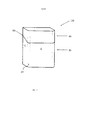
на фиг. 1 изображен вид в перспективном изображении тары, имеющей по меньшей мере одну часть в виде криволинейной кромки согласно варианту осуществления настоящего изобретения;in FIG. 1 is a perspective view of a container having at least one curved edge portion according to an embodiment of the present invention;
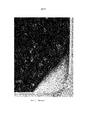
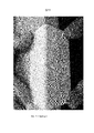
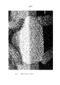
фиг. 2 представляет собой фотографию, на которой показан увеличенный вид поперечного сечения слоистой заготовки согласно первому варианту осуществления настоящего изобретения (Пример 1);FIG. 2 is a photograph showing an enlarged cross-sectional view of a laminate preform according to a first embodiment of the present invention (Example 1);
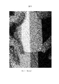
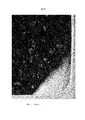
фиг. 3 представляет собой фотографию, на которой показан вид в перспективном изображении заготовки по фиг. 2 (Пример 1);FIG. 3 is a photograph showing a perspective view of the blank of FIG. 2 (Example 1);
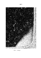
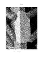
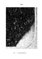
фиг. 4 представляет собой фотографию, на которой показан увеличенный вид поперечного сечения слоистой заготовки согласно второму варианту осуществления настоящего изобретения (Пример 2);FIG. 4 is a photograph showing an enlarged cross-sectional view of a laminate preform according to a second embodiment of the present invention (Example 2);
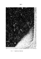
фиг. 5 представляет собой фотографию, на которой показан вид в перспективном изображении заготовки по фиг. 4 (Пример 2);FIG. 5 is a photograph showing a perspective view of the blank of FIG. 4 (Example 2);
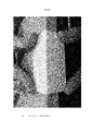
фиг. 6 представляет собой фотографию, на которой показан увеличенный вид поперечного сечения слоистой заготовки согласно настоящему изобретению (Пример 3);FIG. 6 is a photograph showing an enlarged cross-sectional view of a laminate preform according to the present invention (Example 3);
фиг. 7 представляет собой фотографию, на которой показан вид в перспективном изображении заготовки по фиг. 6 (Пример 3);FIG. 7 is a photograph showing a perspective view of the blank of FIG. 6 (Example 3);
фиг. 8 представляет собой фотографию, на которой показан увеличенный вид поперечного сечения слоистой заготовки, не соответствующей настоящему изобретению (Сравнительный пример 1);FIG. 8 is a photograph showing an enlarged cross-sectional view of a laminate preform not corresponding to the present invention (Comparative Example 1);
фиг. 9 представляет собой фотографию, на которой показан вид в перспективном изображении заготовки по фиг. 8 (Сравнительный пример 1);FIG. 9 is a photograph showing a perspective view of the blank of FIG. 8 (Comparative example 1);
фиг. 10 представляет собой фотографию, на которой показан увеличенный вид поперечного сечения слоистой заготовки, не соответствующей настоящему изобретению (Сравнительный пример 2);FIG. 10 is a photograph showing an enlarged cross-sectional view of a laminate preform not corresponding to the present invention (Comparative Example 2);
фиг. 11 представляет собой фотографию, на которой показан вид в перспективном изображении заготовки по фиг. 10 (Сравнительный пример 2);FIG. 11 is a photograph showing a perspective view of the blank of FIG. 10 (Comparative example 2);
Как может быть понятно специалисту в данной области техники, на фиг. 1 показана тара 100 для потребительских товаров, которая может быть образована посредством складывания слоистой заготовки из картона или плотной бумаги, имеющей толщину (T).As may be understood by one of ordinary skill in the art, in FIG. 1 shows a
Тара 100 имеет форму по существу прямоугольного параллелепипеда и содержит часть 30 в виде коробки и шарнирную крышку 40, соединенную с частью 30 в виде коробки по линии 50 шарнира, проходящей по существу по задней стенке тары 100. Наружные размеры и конструкция коробки 30 и крышки 40 тары 100 являются по существу такими же, что и у стандартной сигаретной пачки с шарнирной крышкой. Часть 30 в виде коробки содержит переднюю стенку коробки, заднюю стенку коробки, нижнюю стенку коробки, левую боковую стенку коробки и правую боковую стенку коробки. Шарнирная крышка 40 содержит переднюю стенку крышки, заднюю стенку крышки, верхнюю стенку крышки, левую боковую стенку крышки и правую боковую стенку крышки. Шарнирная крышка 40 выполнена с возможностью поворота вокруг линии 50 шарнира между закрытым положением и открытым положением. В закрытом положении шарнирная крышка 40 закрывает отверстие для доступа тары 100, и стенки шарнирной крышки 40 образуют продолжение соответствующих стенок части 30 в виде коробки. В открытом положении шарнирная крышка 40 поворачивается вокруг линии 50 шарнира с выступанием назад от части 30 в виде коробки и полным открытием отверстия для доступа в верхнем конце части 30 в виде коробки. Часть 30 в виде коробки и шарнирная крышка 40 могут быть образованы вместе из одной слоистой заготовки, имеющей толщину T. Тара может быть собрана из слоистой заготовки и заполнена с использованием стандартного устройства.The
Тара содержит первую плоскую стенку 4, которая на фиг. 1 является боковой стенкой части 30 в виде коробки. Тара также содержит вторую плоскую стенку 8, которая на фиг. 1 является передней стенкой части 30 в виде коробки. Боковая стенка 4 и передняя стенка 8 соединены друг с другом посредством части 20 в виде криволинейной кромки. Также невидимая на виде в перспективном изображении на фиг. 1 внутренняя поверхность части 20 в виде криволинейной кромки содержит множество линий абляции, которые вместе образуют часть 20 в виде криволинейной кромки в случае собранной тары 100.The container contains a first flat wall 4, which in FIG. 1 is a side wall of a
Пять различных слоистых заготовок были изготовлены и сложены с образованием части в виде криволинейной кромки. Детали каждой слоистой заготовки предоставлены ниже, и фотографии каждой слоистой заготовки и их соответствующие части в виде криволинейных кромок показаны на фиг. 2-13. Во всех примерах слоистая заготовка была обеспечена множеством параллельных линий абляции на ее внутренней поверхности. Линии абляции были образованы приложением инструмента для лазерной абляции на внутреннюю поверхность слоистой заготовки для удаления материала с указанной поверхности. Это привело к образованию канавок по существу V-образной формы на внутренней поверхности слоистой заготовки. Целью было определение, какая слоистая заготовка или слоистые заготовки (при складывании) будут образовывать часть в виде криволинейной кромки, имеющую гладкую и плавную кривизну, наиболее приближенную к теоретическому криволинейному профилю. Испытание и выдерживание осуществляли при 23 градусах по Цельсию и 50 процентах относительной влажности согласно ISO 187, через две недели после образования линий абляции.Five different layered blanks were fabricated and folded to form a curved edge portion. Details of each laminate preform are provided below, and photographs of each laminate preform and their corresponding parts in the form of curved edges are shown in FIG. 2-13. In all examples, the layered preform was provided with a plurality of parallel ablation lines on its inner surface. The ablation lines were formed by applying a laser ablation tool to the inner surface of the laminate preform to remove material from the specified surface. This has led to the formation of substantially V-shaped grooves on the inner surface of the laminate preform. The goal was to determine which layered blank or layered blanks (when folded) will form a part in the form of a curved edge having a smooth and smooth curvature that is closest to the theoretical curved profile. Testing and aging were carried out at 23 degrees Celsius and 50 percent relative humidity according to ISO 187, two weeks after the formation of ablation lines.
Пример 1:Example 1:
На фиг. 2 показан увеличенный вид поперечного сечения слоистой заготовки согласно первому варианту осуществления настоящего изобретения (Пример 1). На фиг. 3 показан вид в перспективном изображении заготовки по фиг. 2 (Пример 1).In FIG. 2 is an enlarged cross-sectional view of a laminate preform according to a first embodiment of the present invention (Example 1). In FIG. 3 shows a perspective view of the blank of FIG. 2 (Example 1).
Заготовка по Примеру 1 имеет базовый вес 240 грамм на квадратный метр, толщину (T) 298 микрометров. Было измерено, что каждая линия абляции имеет минимальную остаточную толщину 33 процента от толщины (T) заготовки и ширину абляции 0,49 миллиметра.The workpiece of Example 1 has a base weight of 240 grams per square meter and a thickness (T) of 298 micrometers. It was measured that each ablation line has a minimum residual thickness of 33 percent of the workpiece thickness (T) and an ablation width of 0.49 millimeters.
Зазор составляет 0,7 миллиметра и остаточная жесткость в направлении изгиба, вычисленная на основе жесткости в поперечном направлении перед наслоением, составляет 32 миллиньютон. Жесткость слоистой заготовки перед абляцией составляет 197 миллиньютон в направлении обработки и 98 миллиньютон в поперечном направлении (в данном примере поперечное направление представляет собой направление изгиба).The gap is 0.7 millimeters and the residual stiffness in the bending direction, calculated on the basis of the transverse stiffness before layering, is 32 millinewtons. The stiffness of the laminated preform before ablation is 197 millinewtons in the machining direction and 98 millinewtons in the transverse direction (in this example, the transverse direction is the bending direction).
Как можно видеть на фиг. 2 и 3, было обнаружено, что заготовка по Примеру 1 имеет четко определяемую часть в виде криволинейной кромки, имеющую плавную кривизну, наиболее приближенную к теоретическому криволинейному профилю. Расположение линий абляции не может быть легко идентифицировано на внешней поверхности части в виде криволинейной кромки.As can be seen in FIG. 2 and 3, it was found that the workpiece according to Example 1 has a clearly defined part in the form of a curved edge, having a smooth curvature closest to the theoretical curved profile. The location of the ablation lines cannot be easily identified on the outer surface of the part in the form of a curved edge.
Пример 2:Example 2:
На фиг. 4 показан увеличенный вид поперечного сечения слоистой заготовки согласно второму варианту осуществления настоящего изобретения (Пример 2). На фиг. 5 показан вид в перспективном изображении заготовки по фиг. 4 (Пример 2).In FIG. 4 is an enlarged cross-sectional view of a laminate preform according to a second embodiment of the present invention (Example 2). In FIG. 5 shows a perspective view of the blank of FIG. 4 (Example 2).
Заготовка по Примеру 2 имеет базовый вес 270 грамм на квадратный метр, толщину (T) 340 микрометров. Было измерено, что каждая линия абляции имеет минимальную остаточную толщину 53 процента от толщины (T) заготовки и ширину абляции 0,26 миллиметра.The workpiece of Example 2 has a base weight of 270 grams per square meter and a thickness (T) of 340 micrometers. It was measured that each ablation line has a minimum residual thickness of 53 percent of the workpiece thickness (T) and an ablation width of 0.26 millimeters.
Зазор составляет 0,7 миллиметра и остаточная жесткость в направлении изгиба, вычисленная на основе жесткости в поперечном направлении перед наслоением, составляет 76 миллиньютон. Жесткость слоистой заготовки перед абляцией составляет 290 миллиньютон в направлении обработки и 145 миллиньютон в поперечном направлении (в данном примере поперечное направление представляет собой направление изгиба).The gap is 0.7 millimeters and the residual stiffness in the bending direction, calculated on the basis of the transverse stiffness before layering, is 76 millinewtons. The stiffness of the laminated preform before ablation is 290 millinewtons in the machining direction and 145 millinewtons in the transverse direction (in this example, the transverse direction is the bending direction).
Как можно видеть на фиг. 4 и 5, было обнаружено, что заготовка по Примеру 2 имеет четко определяемую часть в виде криволинейной кромки, имеющую плавную кривизну, наиболее приближенную к теоретическому криволинейному профилю. Расположение линий абляции не может быть легко идентифицировано на внешней поверхности части в виде криволинейной кромки.As can be seen in FIG. 4 and 5, it was found that the workpiece according to Example 2 has a clearly defined part in the form of a curved edge, having a smooth curvature that is closest to the theoretical curved profile. The location of the ablation lines cannot be easily identified on the outer surface of the part in the form of a curved edge.
Пример 3:Example 3:
На фиг. 6 показан увеличенный вид поперечного сечения слоистой заготовки согласно второму варианту осуществления настоящего изобретения (Пример 3). На фиг. 7 показан вид в перспективном изображении заготовки по фиг. 6 (Пример 3).In FIG. 6 is an enlarged cross-sectional view of a laminate preform according to a second embodiment of the present invention (Example 3). In FIG. 7 shows a perspective view of the blank of FIG. 6 (Example 3).
Заготовка по Примеру 3 имеет базовый вес 240 грамм на квадратный метр, толщину (T) 298 микрометров. Измерено, что каждая линия абляции имеет минимальную остаточную толщину 58 процентов от толщины (T) заготовки и ширину абляции 0,25 миллиметра.The workpiece of Example 3 has a base weight of 240 grams per square meter and a thickness (T) of 298 micrometers. It was measured that each ablation line has a minimum residual thickness of 58 percent of the workpiece thickness (T) and an ablation width of 0.25 millimeters.
Зазор составляет 0,7 миллиметра и остаточная жесткость в направлении изгиба, вычисленная на основе жесткости в поперечном направлении перед наслоением, составляет 56 миллиньютон. Жесткость слоистой заготовки перед абляцией составляет 197 миллиньютон в направлении обработки и 98 миллиньютон в поперечном направлении (в данном примере поперечное направление представляет собой направление изгиба).The gap is 0.7 millimeters and the residual stiffness in the bending direction, calculated on the basis of the transverse stiffness before layering, is 56 millinewtons. The stiffness of the laminated preform before ablation is 197 millinewtons in the machining direction and 98 millinewtons in the transverse direction (in this example, the transverse direction is the bending direction).
Как можно видеть на фиг. 6 и 7, было обнаружено, что заготовка по Примеру 3 имеет четко определяемую часть в виде криволинейной кромки, имеющую плавную кривизну, наиболее приближенную к теоретическому криволинейному профилю. Расположение линий абляции не может быть легко идентифицировано на внешней поверхности части в виде криволинейной кромки.As can be seen in FIG. 6 and 7, it was found that the workpiece according to Example 3 has a clearly defined part in the form of a curved edge, having a smooth curvature closest to the theoretical curved profile. The location of the ablation lines cannot be easily identified on the outer surface of the part in the form of a curved edge.
Сравнительный пример 1:Comparative example 1:
На фиг. 8 показан увеличенный вид поперечного сечения слоистой заготовки, не соответствующей варианту осуществления настоящего изобретения (Сравнительный пример 1). На фиг. 9 показан вид в перспективном изображении заготовки по фиг. 6 (Сравнительный пример 1).In FIG. 8 is an enlarged cross-sectional view of a laminate preform not corresponding to an embodiment of the present invention (Comparative Example 1). In FIG. 9 is a perspective view of the blank of FIG. 6 (Comparative example 1).
Заготовка по Сравнительному примеру 1 имеет базовый вес 240 грамм на квадратный метр, толщину (T) 298 микрометров. Измерено, что каждая линия абляции имеет минимальную остаточную толщину 59 процентов от толщины (T) заготовки и ширину абляции 0,36 миллиметра.The workpiece according to Comparative example 1 has a base weight of 240 grams per square meter, thickness (T) 298 micrometers. It was measured that each ablation line has a minimum residual thickness of 59 percent of the workpiece thickness (T) and an ablation width of 0.36 millimeters.
Зазор составляет 2,1 миллиметра. Жесткость слоистой заготовки перед абляцией составляет 197 миллиньютон в направлении обработки и 98 миллиньютон в поперечном направлении (в данном примере поперечное направление представляет собой направление изгиба).The clearance is 2.1 millimeters. The stiffness of the laminated preform before ablation is 197 millinewtons in the machining direction and 98 millinewtons in the transverse direction (in this example, the transverse direction is the bending direction).
Как можно видеть на фиг. 8 и 9, было обнаружено, что заготовка по Сравнительному примеру 1 не имеет четко определяемой части в виде криволинейной кромки. То есть, часть в виде криволинейной кромки не имеет плавной кривизны, приближенной к теоретическому криволинейному профилю. Вместо этого, часть в виде криволинейной кромки переходит неравномерно и случайным образом из первой плоской панели во вторую плоскую панель, при этом хорошо видно отслаивание вдоль части в виде криволинейной кромки.As can be seen in FIG. 8 and 9, it was found that the blank of Comparative Example 1 does not have a clearly defined portion in the form of a curved edge. That is, the part in the form of a curved edge does not have a smooth curvature close to the theoretical curved profile. Instead, the curved edge part transitions unevenly and randomly from the first flat panel to the second flat panel, with peeling along the curved edge part clearly visible.
Сравнительный пример 2:Comparative example 2:
На фиг. 10 показан увеличенный вид поперечного сечения слоистой заготовки, не соответствующей варианту осуществления настоящего изобретения (Сравнительный пример 2). На фиг. 11 показан вид в перспективном изображении заготовки по фиг. 10 (Сравнительный пример 2).In FIG. 10 is an enlarged cross-sectional view of a laminate preform not corresponding to an embodiment of the present invention (Comparative Example 2). In FIG. 11 is a perspective view of the blank of FIG. 10 (Comparative example 2).
Заготовка по Сравнительному примеру 2 имеет базовый вес 240 грамм на квадратный метр, толщину (T) 298 микрометров. Было измерено, что каждая линия абляции имеет минимальную остаточную толщину 66 процентов от толщины (T) заготовки и ширину абляции 0,35 миллиметра. Зазор составляет 0,71 миллиметра. Жесткость слоистой заготовки перед абляцией составляет 197 миллиньютон в направлении обработки и 98 миллиньютон в поперечном направлении (в данном примере поперечное направление представляет собой направление изгиба).The workpiece according to Comparative example 2 has a base weight of 240 grams per square meter, thickness (T) 298 micrometers. It was measured that each ablation line has a minimum residual thickness of 66 percent of the workpiece thickness (T) and an ablation width of 0.35 millimeters. The clearance is 0.71 mm. The stiffness of the laminated preform before ablation is 197 millinewtons in the machining direction and 98 millinewtons in the transverse direction (in this example, the transverse direction is the bending direction).
Как можно видеть на фиг. 10 и 11, было обнаружено, что заготовка по Сравнительному примеру 2 не имеет четко определяемой части в виде криволинейной кромки. То есть, часть в виде криволинейной кромки не имеет плавной кривизны, приближенной к теоретическому криволинейному профилю. Вместо этого, часть в виде криволинейной кромки переходит неравномерно и случайным образом из первой плоской панели во вторую плоскую панель, при этом хорошо видно отслаивание вдоль части в виде криволинейной кромки.As can be seen in FIG. 10 and 11, it was found that the preform of Comparative Example 2 does not have a clearly defined part in the form of a curved edge. That is, the part in the form of a curved edge does not have a smooth curvature close to the theoretical curved profile. Instead, the curved edge part transitions unevenly and randomly from the first flat panel to the second flat panel, with peeling along the curved edge part clearly visible.
На фиг. 2-7 показано, что может быть получена неожиданно более опрятная, более четко определяемая часть в виде криволинейной кромки, имеющая плавную кривизну, наиболее приближенную к теоретическому криволинейному профилю, когда линии абляции наносятся на слоистую заготовку согласно настоящему изобретению.In FIG. 2-7 show that an unexpectedly tidier, more clearly defined portion in the form of a curved edge having a smooth curvature that is closest to the theoretical curved profile when ablation lines are applied to a laminate preform according to the present invention can be obtained.
Claims (27)
Applications Claiming Priority (3)
| Application Number | Priority Date | Filing Date | Title |
|---|---|---|---|
| EP15169514 | 2015-05-27 | ||
| EP15169514.5 | 2015-05-27 | ||
| PCT/EP2016/061994 WO2016189128A1 (en) | 2015-05-27 | 2016-05-27 | Container having improved curved edge |
Publications (3)
| Publication Number | Publication Date |
|---|---|
| RU2017135232A RU2017135232A (en) | 2019-04-05 |
| RU2017135232A3 RU2017135232A3 (en) | 2019-07-30 |
| RU2700952C2 true RU2700952C2 (en) | 2019-09-24 |
Family
ID=53264572
Family Applications (1)
| Application Number | Title | Priority Date | Filing Date |
|---|---|---|---|
| RU2017135232A RU2700952C2 (en) | 2015-05-27 | 2016-05-27 | Container having improved curvilinear edge |
Country Status (15)
| Country | Link |
|---|---|
| US (1) | US20180093817A1 (en) |
| EP (1) | EP3303178B1 (en) |
| JP (1) | JP6876000B2 (en) |
| KR (1) | KR20180013870A (en) |
| CN (1) | CN107660195B (en) |
| AU (1) | AU2016269149A1 (en) |
| BR (1) | BR112017023342B1 (en) |
| ES (1) | ES2758448T3 (en) |
| HK (1) | HK1252552A1 (en) |
| MX (1) | MX2017014905A (en) |
| PH (1) | PH12017501605A1 (en) |
| PL (1) | PL3303178T3 (en) |
| RU (1) | RU2700952C2 (en) |
| UA (1) | UA123356C2 (en) |
| WO (1) | WO2016189128A1 (en) |
Families Citing this family (1)
| Publication number | Priority date | Publication date | Assignee | Title |
|---|---|---|---|---|
| RU2701849C2 (en) * | 2015-05-27 | 2019-10-01 | Филип Моррис Продактс С.А. | Container having improved bevelled edge |
Citations (5)
| Publication number | Priority date | Publication date | Assignee | Title |
|---|---|---|---|---|
| US5143282A (en) * | 1990-08-28 | 1992-09-01 | Philip Morris Incorporated | Apparatus and method for maintaining closed hinged lid boxes |
| EP0900736A2 (en) * | 1997-08-07 | 1999-03-10 | Philip Morris Products Inc. | Packaging blank and container made therefrom |
| CN101925522A (en) * | 2008-01-21 | 2010-12-22 | 菲利普莫里斯生产公司 | Hinge-lid container |
| WO2012123189A1 (en) * | 2011-03-14 | 2012-09-20 | British American Tobacco (Investments) Limited | Pack with round edge |
| EP2700583A1 (en) * | 2012-08-24 | 2014-02-26 | CP (CartPrint) International Trading AG | Blank for producing packaging or the like and method for producing such a blank |
Family Cites Families (7)
| Publication number | Priority date | Publication date | Assignee | Title |
|---|---|---|---|---|
| DE3515775A1 (en) * | 1985-05-02 | 1986-11-06 | Focke & Co (GmbH & Co), 2810 Verden | METHOD AND DEVICE FOR PRODUCING PACKS WITH ROUNDED OR BEVELED EDGES |
| CA2023664C (en) * | 1989-08-22 | 1997-03-18 | Klaus Peter Lamm | Flip-top cartons |
| PL194970B1 (en) * | 1998-06-17 | 2007-07-31 | Focke & Co | Hinge lid pack for cigarettes or such like |
| US6510981B1 (en) * | 1999-06-09 | 2003-01-28 | General Mills, Inc. | Canister with paper and plastic layers and a plastic lid for containing a particulate-type product, such as a ready-to-eat cereal |
| DE10314375A1 (en) * | 2003-03-28 | 2004-10-07 | Focke & Co.(Gmbh & Co. Kg) | Hinged box for cigarettes |
| CA2961652C (en) * | 2014-10-31 | 2019-08-13 | Graphic Packaging International, Inc. | Carton having texture |
| ES2909923T3 (en) * | 2015-07-31 | 2022-05-10 | Graphic Packaging Int Llc | Reinforced boat, combination of a reinforced blank and a bottom blank, and method of forming a boat |
-
2016
- 2016-05-27 JP JP2017559833A patent/JP6876000B2/en active Active
- 2016-05-27 US US15/567,237 patent/US20180093817A1/en not_active Abandoned
- 2016-05-27 BR BR112017023342-8A patent/BR112017023342B1/en active IP Right Grant
- 2016-05-27 EP EP16725152.9A patent/EP3303178B1/en active Active
- 2016-05-27 AU AU2016269149A patent/AU2016269149A1/en not_active Withdrawn
- 2016-05-27 RU RU2017135232A patent/RU2700952C2/en active
- 2016-05-27 WO PCT/EP2016/061994 patent/WO2016189128A1/en active Application Filing
- 2016-05-27 PL PL16725152T patent/PL3303178T3/en unknown
- 2016-05-27 UA UAA201710544A patent/UA123356C2/en unknown
- 2016-05-27 MX MX2017014905A patent/MX2017014905A/en unknown
- 2016-05-27 ES ES16725152T patent/ES2758448T3/en active Active
- 2016-05-27 CN CN201680028050.8A patent/CN107660195B/en active Active
- 2016-05-27 KR KR1020177031842A patent/KR20180013870A/en not_active IP Right Cessation
-
2017
- 2017-09-06 PH PH12017501605A patent/PH12017501605A1/en unknown
-
2018
- 2018-09-14 HK HK18111865.9A patent/HK1252552A1/en unknown
Patent Citations (5)
| Publication number | Priority date | Publication date | Assignee | Title |
|---|---|---|---|---|
| US5143282A (en) * | 1990-08-28 | 1992-09-01 | Philip Morris Incorporated | Apparatus and method for maintaining closed hinged lid boxes |
| EP0900736A2 (en) * | 1997-08-07 | 1999-03-10 | Philip Morris Products Inc. | Packaging blank and container made therefrom |
| CN101925522A (en) * | 2008-01-21 | 2010-12-22 | 菲利普莫里斯生产公司 | Hinge-lid container |
| WO2012123189A1 (en) * | 2011-03-14 | 2012-09-20 | British American Tobacco (Investments) Limited | Pack with round edge |
| EP2700583A1 (en) * | 2012-08-24 | 2014-02-26 | CP (CartPrint) International Trading AG | Blank for producing packaging or the like and method for producing such a blank |
Also Published As
| Publication number | Publication date |
|---|---|
| MX2017014905A (en) | 2018-03-23 |
| WO2016189128A1 (en) | 2016-12-01 |
| EP3303178A1 (en) | 2018-04-11 |
| JP2018515396A (en) | 2018-06-14 |
| US20180093817A1 (en) | 2018-04-05 |
| BR112017023342A2 (en) | 2018-07-17 |
| PL3303178T3 (en) | 2020-08-24 |
| RU2017135232A3 (en) | 2019-07-30 |
| UA123356C2 (en) | 2021-03-24 |
| ES2758448T3 (en) | 2020-05-05 |
| CN107660195B (en) | 2020-06-26 |
| RU2017135232A (en) | 2019-04-05 |
| KR20180013870A (en) | 2018-02-07 |
| CN107660195A (en) | 2018-02-02 |
| EP3303178B1 (en) | 2019-10-23 |
| PH12017501605A1 (en) | 2018-03-05 |
| BR112017023342B1 (en) | 2022-06-14 |
| HK1252552A1 (en) | 2019-05-31 |
| JP6876000B2 (en) | 2021-05-26 |
| AU2016269149A1 (en) | 2017-09-28 |
Similar Documents
| Publication | Publication Date | Title |
|---|---|---|
| US10266301B2 (en) | Round corner container | |
| US20190002188A1 (en) | Container with improved opening | |
| RU2700952C2 (en) | Container having improved curvilinear edge | |
| RU2713480C2 (en) | High strength container | |
| RU2701849C2 (en) | Container having improved bevelled edge | |
| RU2705481C2 (en) | Container with non-square edges | |
| RU2706812C2 (en) | Container with skewed edge and adjacent transverse curved edge | |
| KR102525771B1 (en) | Improved hinge lid containers with lid flaps | |
| WO2017001563A1 (en) | Container having improved flatness | |
| KR20170132734A (en) | Improved container with non-square edges | |
| US20180170657A1 (en) | Container having a plurality of cut edges |