RU2699862C2 - Exhaust casing for exhaust gas of gas turbine engine and gas turbine engine with such exhaust casing for exhaust gas - Google Patents
Exhaust casing for exhaust gas of gas turbine engine and gas turbine engine with such exhaust casing for exhaust gas Download PDFInfo
- Publication number
- RU2699862C2 RU2699862C2 RU2015123480A RU2015123480A RU2699862C2 RU 2699862 C2 RU2699862 C2 RU 2699862C2 RU 2015123480 A RU2015123480 A RU 2015123480A RU 2015123480 A RU2015123480 A RU 2015123480A RU 2699862 C2 RU2699862 C2 RU 2699862C2
- Authority
- RU
- Russia
- Prior art keywords
- segments
- exhaust
- exhaust gas
- casing
- attached
- Prior art date
Links
Images


Classifications
-
- F—MECHANICAL ENGINEERING; LIGHTING; HEATING; WEAPONS; BLASTING
- F01—MACHINES OR ENGINES IN GENERAL; ENGINE PLANTS IN GENERAL; STEAM ENGINES
- F01D—NON-POSITIVE DISPLACEMENT MACHINES OR ENGINES, e.g. STEAM TURBINES
- F01D25/00—Component parts, details, or accessories, not provided for in, or of interest apart from, other groups
- F01D25/08—Cooling; Heating; Heat-insulation
- F01D25/14—Casings modified therefor
- F01D25/145—Thermally insulated casings
-
- F—MECHANICAL ENGINEERING; LIGHTING; HEATING; WEAPONS; BLASTING
- F01—MACHINES OR ENGINES IN GENERAL; ENGINE PLANTS IN GENERAL; STEAM ENGINES
- F01D—NON-POSITIVE DISPLACEMENT MACHINES OR ENGINES, e.g. STEAM TURBINES
- F01D25/00—Component parts, details, or accessories, not provided for in, or of interest apart from, other groups
- F01D25/24—Casings; Casing parts, e.g. diaphragms, casing fastenings
- F01D25/243—Flange connections; Bolting arrangements
-
- F—MECHANICAL ENGINEERING; LIGHTING; HEATING; WEAPONS; BLASTING
- F01—MACHINES OR ENGINES IN GENERAL; ENGINE PLANTS IN GENERAL; STEAM ENGINES
- F01D—NON-POSITIVE DISPLACEMENT MACHINES OR ENGINES, e.g. STEAM TURBINES
- F01D25/00—Component parts, details, or accessories, not provided for in, or of interest apart from, other groups
- F01D25/24—Casings; Casing parts, e.g. diaphragms, casing fastenings
- F01D25/246—Fastening of diaphragms or stator-rings
-
- F—MECHANICAL ENGINEERING; LIGHTING; HEATING; WEAPONS; BLASTING
- F01—MACHINES OR ENGINES IN GENERAL; ENGINE PLANTS IN GENERAL; STEAM ENGINES
- F01D—NON-POSITIVE DISPLACEMENT MACHINES OR ENGINES, e.g. STEAM TURBINES
- F01D25/00—Component parts, details, or accessories, not provided for in, or of interest apart from, other groups
- F01D25/30—Exhaust heads, chambers, or the like
-
- F—MECHANICAL ENGINEERING; LIGHTING; HEATING; WEAPONS; BLASTING
- F01—MACHINES OR ENGINES IN GENERAL; ENGINE PLANTS IN GENERAL; STEAM ENGINES
- F01D—NON-POSITIVE DISPLACEMENT MACHINES OR ENGINES, e.g. STEAM TURBINES
- F01D9/00—Stators
- F01D9/02—Nozzles; Nozzle boxes; Stator blades; Guide conduits, e.g. individual nozzles
- F01D9/04—Nozzles; Nozzle boxes; Stator blades; Guide conduits, e.g. individual nozzles forming ring or sector
- F01D9/042—Nozzles; Nozzle boxes; Stator blades; Guide conduits, e.g. individual nozzles forming ring or sector fixing blades to stators
-
- F—MECHANICAL ENGINEERING; LIGHTING; HEATING; WEAPONS; BLASTING
- F02—COMBUSTION ENGINES; HOT-GAS OR COMBUSTION-PRODUCT ENGINE PLANTS
- F02C—GAS-TURBINE PLANTS; AIR INTAKES FOR JET-PROPULSION PLANTS; CONTROLLING FUEL SUPPLY IN AIR-BREATHING JET-PROPULSION PLANTS
- F02C7/00—Features, components parts, details or accessories, not provided for in, or of interest apart form groups F02C1/00 - F02C6/00; Air intakes for jet-propulsion plants
- F02C7/20—Mounting or supporting of plant; Accommodating heat expansion or creep
-
- F—MECHANICAL ENGINEERING; LIGHTING; HEATING; WEAPONS; BLASTING
- F02—COMBUSTION ENGINES; HOT-GAS OR COMBUSTION-PRODUCT ENGINE PLANTS
- F02K—JET-PROPULSION PLANTS
- F02K1/00—Plants characterised by the form or arrangement of the jet pipe or nozzle; Jet pipes or nozzles peculiar thereto
- F02K1/78—Other construction of jet pipes
- F02K1/82—Jet pipe walls, e.g. liners
- F02K1/822—Heat insulating structures or liners, cooling arrangements, e.g. post combustion liners; Infra-red radiation suppressors
-
- Y—GENERAL TAGGING OF NEW TECHNOLOGICAL DEVELOPMENTS; GENERAL TAGGING OF CROSS-SECTIONAL TECHNOLOGIES SPANNING OVER SEVERAL SECTIONS OF THE IPC; TECHNICAL SUBJECTS COVERED BY FORMER USPC CROSS-REFERENCE ART COLLECTIONS [XRACs] AND DIGESTS
- Y02—TECHNOLOGIES OR APPLICATIONS FOR MITIGATION OR ADAPTATION AGAINST CLIMATE CHANGE
- Y02T—CLIMATE CHANGE MITIGATION TECHNOLOGIES RELATED TO TRANSPORTATION
- Y02T50/00—Aeronautics or air transport
- Y02T50/60—Efficient propulsion technologies, e.g. for aircraft
Abstract
Description
УРОВЕНЬ ТЕХНИКИBACKGROUND
Настоящее изобретение относится к технологии газотурбинных двигателей. Оно относится к выхлопному кожуху для отработавшего газа газотурбинного двигателя согласно ограничительной части пункта 1 формулы изобретения.The present invention relates to the technology of gas turbine engines. It relates to an exhaust casing for an exhaust gas of a gas turbine engine according to the preamble of paragraph 1 of the claims.
Оно дополнительно относится к газотурбинному двигателю с таким выхлопным кожухом для отработавшего газа.It further relates to a gas turbine engine with such an exhaust casing for exhaust gas.
ПРЕДШЕСТВУЮЩИЙ УРОВЕНЬ ТЕХНИКИBACKGROUND OF THE INVENTION
Документ EP 2565400 A2 раскрывает газовый канал для газотурбинного двигателя, причем газовый канал образован концентрическими внутренним кожухом и внешним кожухом, который концентрически охватывает внутренний кожух на расстоянии, и через который отработавшие газы отводятся из газотурбинного двигателя наружу. Внутренний кожух и внешний кожух соединены посредством множества радиальных опорных стоек. Опорные стойки, внешний кожух и внутренний кожух снабжены в каждом случае жаропрочной обкладкой для защиты от горячего отработавшего газа. Легкая доступность и экстенсивное снижение тепловых напряжений достигается обкладками опорных стоек внешнего кожуха и внутреннего кожуха, разделенными в каждом случае на множество отдельных сегментов, которые закреплены на опорной конструкции таким образом, что возможно отдельное тепловое расширение отдельных сегментов.EP 2565400 A2 discloses a gas channel for a gas turbine engine, the gas channel being formed by a concentric inner casing and an outer casing that concentrically covers the inner casing at a distance, and through which exhaust gases are led out of the gas turbine engine to the outside. The inner casing and the outer casing are connected by a plurality of radial support legs. The support legs, the outer casing and the inner casing are provided in each case with a heat-resistant lining to protect against hot exhaust gas. Easy accessibility and an extensive reduction of thermal stresses is achieved by the plates of the supporting posts of the outer casing and the inner casing, divided in each case into many separate segments, which are mounted on the supporting structure in such a way that a separate thermal expansion of the individual segments is possible.
Однако для крепления сегментов используются несущие балки. Эти несущие балки и специальная «звездообразная» форма внутреннего/наружного фланцев подвержены воздействию высоких температур и напряжений в установившемся режиме и, следовательно, некоторые параметры малоцикловой усталости (LCF) и пластической деформации опорной конструкции не выполняются.However, carrier beams are used to secure the segments. These load-bearing beams and a special “star-shaped” shape of the inner / outer flanges are subject to high temperatures and stresses in steady state and, therefore, some parameters of low-cycle fatigue (LCF) and plastic deformation of the supporting structure are not fulfilled.
Более того, соединительные болты подвержены воздействию основного газового потока. Высокая температура болтов и соединяемых частей и изменения температуры как в переходном, так и в установившемся режиме может привести к пластической деформации материала болта и, следовательно, к потере предварительного натяжения болта.Moreover, the connecting bolts are exposed to the main gas stream. The high temperature of the bolts and the parts to be connected and temperature changes in both the transitional and steady state conditions can lead to plastic deformation of the bolt material and, consequently, to loss of the pretension of the bolt.
СУЩНОСТЬ ИЗОБРЕТЕНИЯSUMMARY OF THE INVENTION
Задачей настоящего изобретения является обеспечение новой конструкции выхлопного кожуха для отработавшего газа, которая исключает недостатки известной конструкции, и которая компенсирует тепловое расширение и устойчива к динамическим нагрузкам.The present invention is the provision of a new design of the exhaust casing for the exhaust gas, which eliminates the disadvantages of the known design, and which compensates for thermal expansion and is resistant to dynamic loads.
Дополнительной задачей настоящего изобретения является обеспечение газотурбинного двигателя с таким выхлопным кожухом для отработавшего газа.An additional objective of the present invention is the provision of a gas turbine engine with such an exhaust casing for exhaust gas.
Эти и другие задачи достигаются выхлопным кожухом для отработавшего газа по п.1 и газотурбинным двигателем по п.15.These and other tasks are achieved by the exhaust casing for exhaust gas according to claim 1 and the gas turbine engine according to
Выхлопной кожух для отработавшего газа газотурбинного двигателя согласно изобретению содержит кольцевой внутренний корпус и кольцевой внешний корпус, которые расположены концентрически вокруг оси машины упомянутого газотурбинного двигателя, чтобы образовать между ними кольцевой канал для отработавшего газа, в результате чего упомянутый внутренний корпус и/или упомянутый внешний корпус состоят из множества сегментов, которые прикреплены к опорной конструкции.An exhaust casing for exhaust gas of a gas turbine engine according to the invention comprises an annular inner casing and an annular outer casing which are concentrically around the axis of the machine of said gas turbine engine to form an annular channel for exhaust gas between them, as a result of which said inner casing and / or said outer casing consist of many segments that are attached to the supporting structure.
Она отличается тем, что упомянутые сегменты прикреплены к упомянутой опорной конструкции в некоторых точках крепления, которые распределены по площади упомянутых сегментов, так что упомянутые сегменты прикреплены к упомянутой опорной конструкции в течение всего термического цикла двигателя, не препятствуя тепловому расширению.It is characterized in that said segments are attached to said supporting structure at certain attachment points that are distributed over the area of said segments, so that said segments are attached to said supporting structure throughout the entire thermal cycle of the engine without interfering with thermal expansion.
Согласно варианту выполнения оригинального выхлопного кожуха для отработавшего газа, все сегменты содержат центральную точку крепления, где упомянутые сегменты прикреплены к упомянутой опорной конструкции, так что предотвращается перемещение упомянутых сегментов в осевом, радиальном и тангенциальном направлениях.According to an embodiment of the original exhaust gas casing, all segments comprise a central attachment point where said segments are attached to said supporting structure, so that said segments are prevented from moving in axial, radial and tangential directions.
Конкретно, упомянутые сегменты прикреплены в упомянутой центральной точке крепления посредством крепежного болта, который ввинчен через держатель на обратной стороне упомянутых сегментов в крепежный штифт, закрепленный на упомянутой опорной конструкции.Specifically, said segments are attached at said central attachment point by means of a fixing bolt that is screwed through a holder on the back of said segments into a fixing pin secured to said supporting structure.
Более конкретно, упомянутый крепежный штифт закреплен на упомянутой опорной конструкции посредством крепежной трубки, которая прикреплена одним концом к упомянутой опорной конструкции и принимает на другом конце упомянутый крепежный штифт.More specifically, said fixing pin is fixed to said supporting structure by a fixing tube that is attached at one end to said supporting structure and receives said fixing pin at the other end.
Согласно другому варианту выполнения изобретения все сегменты содержат направляющую в осевом направлении точку крепления, расположенную на осевой линии упомянутых сегментов, где упомянутые сегменты закреплены на упомянутой опорной конструкции, так что предотвращается перемещение упомянутых сегментов в тангенциальном направлении.According to another embodiment of the invention, all segments comprise an axial directional attachment point located on an axial line of said segments, where said segments are fixed to said supporting structure, so that said segments are prevented from moving in a tangential direction.
Конкретно, упомянутые сегменты прикреплены в упомянутой направляющей в осевом направлении точке крепления посредством осевого направляющего штифта, который закреплен на держателе с обратной стороны упомянутых сегментов и скользяще зацепляет крепежный штифт, закрепленный на упомянутой опорной конструкции.Specifically, said segments are fixed in said axial direction of the attachment point by means of an axial guide pin which is fixed to the holder on the back of said segments and slider engages a fixing pin fixed to said supporting structure.
Более конкретно, упомянутый крепежный штифт закреплен на упомянутой опорной конструкции посредством крепежной трубки, которая прикреплена одним концом к упомянутой опорной конструкции и принимает на другом конце упомянутый крепежный штифт.More specifically, said fixing pin is fixed to said supporting structure by a fixing tube that is attached at one end to said supporting structure and receives said fixing pin at the other end.
Согласно дополнительному варианту выполнения изобретения упомянутый выхлопной кожух для отработавшего газа может быть разделен на две части по линии разъема, и все упомянутые сегменты, за исключением этих сегментов с линией разъема упомянутого внутреннего корпуса, опирающихся на упомянутую линию разъема, содержат четыре боковые точки крепления, расположенные на четырех кромках упомянутых сегментов, где упомянутые сегменты закреплены на упомянутой опорной конструкции, так что предотвращается перемещение упомянутых сегментов в радиальном направлении, но обеспечивается возможность теплового расширения, состоящего из осевого и тангенциального компонентов.According to a further embodiment of the invention, said exhaust casing for exhaust can be divided into two parts along a connector line, and all said segments, with the exception of these segments with a connector line of said inner housing, supported by said connector line, comprise four lateral attachment points located on the four edges of said segments, where said segments are fixed to said supporting structure, so that said segments are prevented from moving radially direction, but provides the possibility of thermal expansion, consisting of axial and tangential components.
Конкретно, упомянутые сегменты прикреплены в упомянутых боковых точках крепления посредством крепежного болта, который ввинчен через держатель на обратной стороне упомянутых сегментов в крепежный штифт, закрепленный на упомянутой опорной конструкции, в результате чего упомянутый держатель содержит вытянутое отверстие с определенной ориентацией и длиной.Specifically, said segments are attached at said lateral attachment points by means of a fixing bolt that is screwed through a holder on the back of said segments into a fixing pin fixed to said supporting structure, whereby said holder comprises an elongated hole with a specific orientation and length.
Более конкретно, упомянутый крепежный штифт закреплен на упомянутой опорной конструкции посредством крепежной трубки, которая прикреплена одним концом к упомянутой опорной конструкции и принимает на другом конце упомянутый крепежный штифт.More specifically, said fixing pin is fixed to said supporting structure by a fixing tube that is attached at one end to said supporting structure and receives said fixing pin at the other end.
Согласно еще одному варианту выполнения изобретения упомянутый внутренний корпус и внешний корпус соединены посредством множества радиальных стоек, и каждая из упомянутых стоек содержит радиальное ребро, которое закрыто передним и задним сегментами стойки, имеющими переднюю кромку и заднюю кромку, которые каждый передний и задний сегменты стоек закреплены на упомянутом радиальном ребре во множестве точек крепления, распределенных вдоль упомянутых передних и задних кромок.According to another embodiment of the invention, said inner casing and an outer casing are connected by a plurality of radial struts, and each of said struts comprises a radial rib that is closed by the front and rear segments of the strut having a leading edge and a trailing edge, which each front and rear segments of the struts are fixed on said radial rib in a plurality of attachment points distributed along said leading and trailing edges.
Конкретно, каждый из упомянутых переднего и заднего сегментов стойки имеет три точки крепления, содержащие среднюю точку крепления, точку крепления со стороны втулки и точку крепления со стороны вершины.Specifically, each of said front and rear leg segments has three attachment points comprising a middle attachment point, an attachment point on the sleeve side, and an attachment point on the apex side.
Более конкретно, в средней точке крепления переднего сегмента стойки крепежный болт используется для крепления упомянутого переднего сегмента стойки в радиальном, осевом и тангенциальном направлениях, в то время как в точках крепления со стороны втулки и вершины обеспечена возможность теплового расширения в радиальном направлении.More specifically, at the mid-point of attachment of the front pillar segment, a mounting bolt is used to fasten said front pillar segment in the radial, axial and tangential directions, while at the attachment points from the sleeve and the top, radial thermal expansion is possible.
Более конкретно, в средней точке крепления заднего сегмента стойки используется фиксатор для крепления упомянутого заднего сегмента стойки, таким образом обеспечивая возможность теплового расширения только в осевом направлении, в то время как в точках крепления со стороны втулки и вершины обеспечена возможность теплового расширения в радиальном и осевом направлениях.More specifically, a latch is used at the mid-point of attachment of the rear leg segment of the rack to fasten the aforementioned rear leg segment, thereby allowing thermal expansion only in the axial direction, while at the attachment points on the side of the sleeve and the top, thermal expansion is possible in radial and axial directions.
Газотурбинный двигатель согласно изобретению содержит компрессор, по меньшей мере одну камеру сгорания и одну турбину, и выхлопной кожух для отработавшего газа, через который горячие отработавшие газы выходят из упомянутого газотурбинного двигателя.The gas turbine engine according to the invention comprises a compressor, at least one combustion chamber and one turbine, and an exhaust casing for exhaust gas through which hot exhaust gases exit the gas turbine engine.
Она отличается тем, что выхлопной кожух для отработавшего газа является выхлопным кожухом для отработавшего газа согласно изобретению.It is characterized in that the exhaust casing for exhaust gas is an exhaust casing for exhaust gas according to the invention.
КРАТКОЕ ОПИСАНИЕ ЧЕРТЕЖЕЙBRIEF DESCRIPTION OF THE DRAWINGS
Теперь настоящее изобретение подлежит более подробному описанию посредством различных вариантов выполнения и со ссылкой на прилагаемые чертежи.Now the present invention is to be described in more detail by means of various embodiments and with reference to the accompanying drawings.
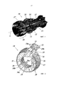
Фиг. 1 показывает частичное сечение газотурбинного двигателя типа GT24/26, которая может использовать выхлопной кожух для отработавшего газа настоящего изобретения;FIG. 1 shows a partial cross-section of a GT24 / 26 type gas turbine engine that may use an exhaust casing for exhaust gas of the present invention;
Фиг. 2 показывает на виде в перспективе различные сегменты (с их точками крепления) выхлопного кожуха для отработавшего газа согласно варианту выполнения изобретения;FIG. 2 shows in perspective view various segments (with their attachment points) of an exhaust casing for exhaust gas according to an embodiment of the invention;
Фиг. 3 показывает точки крепления (в этом примере, шесть) сегмента внутреннего выхлопного кожуха для отработавшего газа согласно Фиг. 2;FIG. 3 shows the attachment points (in this example, six) of the segment of the inner exhaust casing for the exhaust gas according to FIG. 2;
Фиг. 4 показывает точки крепления (в этом примере, шесть) сегмента внешнего выхлопного кожуха для отработавшего газа согласно Фиг. 2;FIG. 4 shows the attachment points (in this example, six) of the segment of the external exhaust casing for the exhaust gas according to FIG. 2;
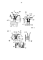
Фиг. 5 и 6 показывают конфигурацию центрального средства крепления сегмента внутренней с Фиг. 3, которое закрепляет сегмент в радиальном, осевом и тангенциальном (или периферическом) направлениях;FIG. 5 and 6 show the configuration of the central fastening means of the inner segment of FIG. 3, which fixes the segment in the radial, axial and tangential (or peripheral) directions;
Фиг. 7 показывает конфигурацию расположенного на четырех кромках средства крепления сегмента внутренней с Фиг. 3, которое закрепляет сегмент в радиальном направлении, но обеспечивает возможность теплового расширения как в осевом, так и тангенциальном направлениях;FIG. 7 shows the configuration of the inner segment fastening means of FIG. 4 located on the four edges. 3, which fixes the segment in the radial direction, but provides the possibility of thermal expansion in both axial and tangential directions;
Фиг. 8 и 9 показывают конфигурацию направляющего в осевом направлении средства крепления сегмента внутренней с Фиг. 3, которое закрепляет сегмент в тангенциальном (или периферическом) направлении, но обеспечивает возможность теплового расширения в радиальном и осевом направлениях;FIG. 8 and 9 show the configuration of the axial guide means for securing the segment of the inner with FIG. 3, which secures the segment in a tangential (or peripheral) direction, but allows thermal expansion in the radial and axial directions;
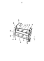
Фиг. 10 показывает верхнюю половину опорной конструкции, используемой для поддерживания сегментов выхлопного кожуха для отработавшего газа согласно Фиг. 2;FIG. 10 shows the upper half of the support structure used to support the segments of the exhaust exhaust casing of FIG. 2;
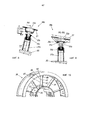
Фиг. 11 показывает стойку выхлопного кожуха для отработавшего газа согласно Фиг. 2 с его передним и задним сегментами и их точками крепления (в этом случае, три);FIG. 11 shows an exhaust gas exhaust strut according to FIG. 2 with its front and rear segments and their attachment points (in this case, three);
Фиг. 12 показывает конфигурацию центрального средства крепления заднего сегмента с Фиг. 11, которое закрепляет сегмент в периферическом направлении, но обеспечивает возможность теплового расширения в радиальном и осевом направлениях;FIG. 12 shows the configuration of the central rear segment attachment means of FIG. 11, which secures the segment in the peripheral direction, but allows thermal expansion in the radial and axial directions;
Фиг. 13 показывает конфигурацию центрального средства крепления переднего сегмента с Фиг. 11, которое закрепляет сегмент в периферическом, радиальном и осевом направлениях; иFIG. 13 shows the configuration of the central fastening means of the front segment of FIG. 11, which secures the segment in the peripheral, radial and axial directions; and
Фиг. 14 показывает конфигурацию средства крепления переднего сегмента со стороны втулки и вершины с Фиг. 11, которое закрепляет сегмент в периферическом и осевом направлениях, но обеспечивает возможность теплового расширения в радиальном направлении.FIG. 14 shows the configuration of the fastening means of the front segment from the side of the sleeve and the top of FIG. 11, which secures the segment in the peripheral and axial directions, but allows thermal expansion in the radial direction.
ПОДРОБНОЕ ОПИСАНИЕ РАЗЛИЧНЫХ ВАРИАНТОВ ВЫПОЛНЕНИЯ ИЗОБРЕТЕНИЯDETAILED DESCRIPTION OF DIFFERENT EMBODIMENTS OF THE INVENTION
Фиг. 1 показывает частичное сечение газотурбинного двигателя типа GT24/26, которая может использовать выхлопной кожух для отработавшего газа настоящего изобретения. Газотурбинный двигатель 10 с Фиг. 1 является типом с промежуточным перегревом пара, содержащая последующее сжигание. Она имеет ротор 11, который окружен кожухом 12 и вращается вокруг оси A машины. Компрессор 13 сжимает воздух, который используется в первой камере 14 сгорания для сжигания топлива, для того чтобы создать горячий газ. Горячий газ из первой камеры 14 сгорания, который по-прежнему содержит кислород, приводит в движение турбину 15 высокого давления (ВД) и затем используется для сжигания топлива во второй камере 16 сгорания. Перегретый горячий газ второй камеры 16 сгорания затем приводит в движение турбину 17 низкого давления (НД) и, в конечном счете, выходит из газотурбинного двигателя 10 через выхлопной кожух 18 для отработавшего газа.FIG. 1 shows a partial cross-section of a GT24 / 26 type gas turbine engine that may use an exhaust casing for the exhaust gas of the present invention. The
Выхлопной кожух 18 для отработавшего газа соосно с осью A машины содержит (Фиг. 2) внутренний корпус 21 и внешний корпус 19, которые соединены множеством радиальных стоек 20 и равномерно распределены по окружности.The
Настоящее изобретение теперь рассматривает принцип крепления различных кольцевых сегментов (22, 23 и 26, 27 и 28 на Фиг. 2) и спрямляющих поток стоек (24, 25 на Фиг. 2) к кожуху и его опорной конструкции (см. Фиг. 10). Конструкция средства крепления различных сегментов должна компенсировать тепловое расширение и быть устойчивой к динамическим нагрузкам.The present invention now considers the principle of securing various annular segments (22, 23 and 26, 27 and 28 in Fig. 2) and flow-straightening struts (24, 25 in Fig. 2) to the casing and its supporting structure (see Fig. 10) . The design of the fastener for various segments should compensate for thermal expansion and be resistant to dynamic loads.
В общем, различные сегменты внутреннего и внешнего корпуса 19, 21 и стоек 20 прикреплены к опорной конструкции контролируемым предварительным натяжением болта в холодном состоянии. Согласно настоящему изобретению, части закреплены в течение всего термического цикла двигателя, но по-прежнему обеспечивается возможность их свободного теплового расширения.In general, the various segments of the inner and
Как показано в варианте выполнения с Фиг. 2, имеется десять стоек 20. Одна стойка расположена в положении на 6 часов. Каждая стойка 20 имеет левый и правый сегменты 22, 23 внешней, левый и правый сегменты 26, 27 внутренней, и передний и задний сегменты 24, 25 стойки.As shown in the embodiment of FIG. 2, there are ten
Каждый сегмент (внутренней и внешней) имеет в общей сложности шесть точек 29a-c и 30a-c крепления/соединения (см. Фиг. 3 и 4) с опорной конструкцией, за исключением сегментов 28 с линией разъема на внутреннем корпусе 21, которые достаточно узкие и не содержат пространства для полного комплекта креплений, но взамен используют три точки крепления.Each segment (internal and external) has a total of six attachment /
Сегменты 23, 27 присоединены в их шести точках 29a-c и 30a-c крепления/соединения к опорной конструкции (31 на Фиг. 10) по следующему принципу крепления сегментов и способностью к тепловому расширению:
1. Центральное крепление (точка крепления) 29b или 30b (см. Фиг. 5 и 6) предотвращает перемещение во всех трех направлениях (x: осевом, R: радиальном и Ф: тангенциальном; смотри соответствующие обозначения на Фиг. 5 и 6).1. The central mount (attachment point) 29b or 30b (see Figs. 5 and 6) prevents movement in all three directions (x: axial, R: radial and Φ: tangential; see the corresponding designations in Figs. 5 and 6).
2. Боковые крепления 29a, 30a (смотри Фиг. 3, 4 и 7) предотвращают перемещение в радиальном направлении, но обеспечивают возможность теплового расширения сегментов 23, 27, состоящего из осевого и тангенциального компонентов (x и Ф; Фиг. 7(c)). Поскольку разница температур на одном сегменте (среднее по времени в осевом направлении по сравнению с тангенциальным направлением) не такое значительное, температурные деформации в обоих направлениях считаются одновременными и линейно зависимыми от средней температуры сегмента. Свобода перемещения достигнута вытянутым отверстием (54 на Фиг. 7(c)) на держателе 33a сегмента с определенной ориентацией и длиной. Болтовое соединение (крепежный болт 35a) с контролируемым предварительным натяжением гарантирует контакт между сегментом и креплением в течение всего термического цикла, создавая силу трения, противодействующую тепловому расширению/увеличению.2. Side mounts 29a, 30a (see Figs. 3, 4 and 7) prevent radial movement, but allow thermal expansion of
3. Осевая направляющая шпонка (30c на Фиг. 3, 8 и 9) предотвращает перемещение в тангенциальном направлении (Ф). Направляющая с осевым направляющим штифтом 35c, расположенная на осевой линии сегмента, должна удерживать сегменты в симметричных положениях во время термического цикла, что важно для удержания под контролем изменения размеров межсегментных зазоров во время цикла.3. An axial guide key (30c in FIGS. 3, 8 and 9) prevents tangential movement (F). A guide with an
В центральной точке 29b, 30b (1) крепления держатель 33b приварен к обратной стороне сегмента 27 непосредственно под отверстием 32b (Фиг. 5, 6). Опорная пластина 34b усиливает основание держателя 33b. Крепежный болт 35b ввинчен через канал в держателе 33b и опорной пластине 34b в крепежный штифт 36b. Крепежный штифт 36b принят в и приварен к крепежной трубке 37b, которая закреплена на опорной конструкции 31. Высота крепежного штифта 36b может быть отрегулирована путем его смещения относительно крепежной трубки 37b до сварки. Фиг. 6 показывает сечение вдоль линии A1-A1 на Фиг. 5.At the
В боковых точках 29a, 30a (2) крепления держатель 33a приварен к обратной стороне сегмента 27 непосредственно под отверстием 32a (Фиг. 7). Опорная пластина 34a усиливает основание держателя 33a. Крепежный болт 35a ввинчен через канал вытянутого отверстия 54 в держателе 33a и опорной пластине 34a в крепежный штифт 36a. Крепежный штифт 36a принят в и приварен к крепежной трубке 37a, которая закреплена на опорной конструкции 31. Высота крепежного штифта 36a может быть отрегулирована путем его смещения относительно крепежной трубки 37a до сварки. Фиг. 7(b) и Фиг. 7(c) показывают сечения вдоль линии A2-A2 и A3-A3 на Фиг. 7(a).At the
В направляющей в осевом направлении точке 29c, 30c (3) крепления держатель 33c приварен к обратной стороне сегмента 27 непосредственно под отверстием 32c (Фиг. 8 и 9). Опорная пластина 34c усиливает основание держателя 33c. Осевой направляющий штифт 35c скользяще зацепляет крепежный штифт 36c. Крепежный штифт 36c принят в и приварен к крепежной трубке 37c, которая закреплена на опорной конструкции 31. Высота крепежного штифта 36c может быть отрегулирована путем его смещения относительно крепежной трубки 37c до сварки. Фиг. 9 показывает сечение вдоль линии A4-A4 на Фиг. 8.In the axial direction of the
Стойки 20 закрыты передним (передняя кромка LE) и задним (задняя кромка ТЕ) сегментами 24, 25 стоек, которые в конечном счете (после сборки с опорной конструкцией) привариваются посередине стойки. Каждый сегмент 24 и 25 имеет три точки 40-42 и 43-45 крепления (Фиг. 11). Все точки крепления кожуха стойки лежат в одной плоскости.
Принцип крепления с учетом теплового расширения состоит в следующем:The principle of fastening, taking into account thermal expansion, is as follows:
1. Точка крепления размещается на LE стороне (сегмента 24 стойки), посередине газового канала, заставляя кожух стойки равномерно расширяться в радиальном направлении по направлению к втулке и вершине. Крепежный болт 51 (Фиг. 13) размещается на LE (сегмент 24) посередине стойки 20 (точка 41 крепления), чтобы предотвратить осевое, радиальное и тангенциальное перемещение (x, R и Ф). Фиг. 13(b) сечение вдоль линии A5-A5 на Фиг. 13(a). Крепежный болт 51 ввинчен через канал в соединительной пластине 50 сегмента 24 стойки в крепежный штифт 52, который ввинчен в и приварен к ребру 39 опорной конструкции 31 или 38.1. The attachment point is located on the LE side (rack segment 24), in the middle of the gas channel, causing the rack housing to expand uniformly in the radial direction towards the sleeve and the apex. A mounting bolt 51 (FIG. 13) is placed on the LE (segment 24) in the middle of the strut 20 (mounting point 41) to prevent axial, radial, and tangential movement (x, R, and Φ). FIG. 13 (b) is a section along line A5-A5 of FIG. 13 (a). The mounting
2. Крепления на LE со стороны втулки и вершины (точки 40 и 42 крепления) обеспечивают возможность теплового расширения в радиальном направлении (R, с трением, вызванным предварительным натяжением болта), но предотвращают перемещение в осевом и тангенциальном направлениях (x и Ф). Конфигурация показана на Фиг. 14. Свобода перемещения достигнута вытянутым отверстием 54’ на сегменте, ориентированном радиально (Фиг. 14(a)). Крепежный болт 48 ввинчен через вытянутое отверстие 54’ в соединительной пластине 47 сегмента 24 стойки в крепежный штифт 52, который ввинчен в и приварен к ребру 39 опорной конструкции 31 или 38. Во всех случаях для болта используется шайба 53.2. Fastenings on LE from the side of the sleeve and the top (fastening points 40 and 42) provide the possibility of thermal expansion in the radial direction (R, with friction caused by pretensioning of the bolt), but prevent movement in the axial and tangential directions (x and Ф). The configuration is shown in FIG. 14. Freedom of movement is achieved by elongated hole 54 ’on the segment oriented radially (Fig. 14 (a)). The fixing
3. Крепежный штифт посередине (точка 44 крепления) ТЕ (сегмент 25) совпадает по радиальному положению с точкой крепления на стороне LE (сегмент 24) и обеспечивает возможность теплового перемещения только в осевом направлении.3. The fixing pin in the middle (mounting point 44) TE (segment 25) coincides in radial position with the mounting point on the LE side (segment 24) and allows thermal movement only in the axial direction.
4. Крепежные штифты (46 на Фиг. 12) ТЕ (сегмент 25) стороны втулки и вершины (точки 43 и 45 крепления) обеспечивают возможность теплового расширения в радиальном и осевом направлениях (R и x). Крепежный штифт 46 ввинчен в или приварен к ребру 39. Он продолжается через радиальное вытянутое отверстие 54’ в соединительной пластине 47 сегмента 25 стойки. Фиг. 12(b) сечение Фиг. 12(a).4. Fixing pins (46 in Fig. 12) TE (segment 25) of the sleeve side and the top (attachment points 43 and 45) allow thermal expansion in the radial and axial directions (R and x). The
СПИСОК ССЫЛОЧНЫХ ПОЗИЦИЙLIST OF REFERENCE POSITIONS
10 газотурбинный двигатель (например, GT26)10 gas turbine engine (e.g. GT26)
11 ротор11 rotor
12 кожух12 casing
13 компрессор13 compressor
14, 16 камера сгорания14, 16 combustion chamber
15 турбина высокого давления (HP)15 high pressure turbine (HP)
17 турбина низкого давления (LP)17 low pressure turbine (LP)
18 выхлопной кожух для отработавшего газа18 exhaust casing for exhaust gas
19 внешний корпус19 outer casing
20 стойка20 rack
21 внутренний корпус21 inner case
22, 23 сегмент (внешний корпус) или внешний сегмент 22, 23 segment (outer casing) or outer segment
24, 25 сегмент стойки24, 25 rack segment
26, 27 сегмент (внутренний корпус) или внутренний сегмент 26, 27 segment (inner case) or inner segment
28 сегмент с линией разъема28 segment with connector line
29a-c точка крепления (соединения) (внешний сегмент)29a-c attachment point (connection) (outer segment)
30а-с точка крепления (соединения) (внутренний сегмент)30a-c attachment point (connection) (inner segment)
31 опорная конструкция31 support structure
32а-с отверстие32a-c hole
ЗЗа-с держательЗЗа-с holder
34а-с опорная пластина34a-c support plate
35а, b крепежный болт35a, b fixing bolt
35с осевой направляющий штифт35c axial guide pin
З6а-с крепежный штифтZ6a-s fixing pin
37а-с крепежная трубка37a-c fixing tube
38 половина опорной конструкции38 half of the supporting structure
39 ребро (стойка)39 rib (stand)
40-42 точка крепления (передняя кромка LE)40-42 attachment point (leading edge LE)
43-45 точка крепления (задняя кромка ТЕ)43-45 attachment point (trailing edge TE)
46 крепежный штифт46 fixing pin
47 соединительная пластина47 connecting plate
48 крепежный болт48 fixing bolt
49 крепежный штифт49 fixing pin
50 соединительная пластина50 connecting plate
51 крепежный болт51 fixing bolt
52 крепежный штифт52 fixing pin
53 шайба53 washer
54, 54’ вытянутое отверстие54, 54 ’elongated hole
А ось машиныAnd the axis of the car
Claims (12)
Applications Claiming Priority (2)
| Application Number | Priority Date | Filing Date | Title |
|---|---|---|---|
| EP14173014.3A EP2957730B8 (en) | 2014-06-18 | 2014-06-18 | Exhaust gas liner with fixation spots for a gas turbine |
| EP14173014.3 | 2014-06-18 |
Publications (3)
| Publication Number | Publication Date |
|---|---|
| RU2015123480A RU2015123480A (en) | 2017-01-10 |
| RU2015123480A3 RU2015123480A3 (en) | 2019-01-17 |
| RU2699862C2 true RU2699862C2 (en) | 2019-09-11 |
Family
ID=50942632
Family Applications (1)
| Application Number | Title | Priority Date | Filing Date |
|---|---|---|---|
| RU2015123480A RU2699862C2 (en) | 2014-06-18 | 2015-06-17 | Exhaust casing for exhaust gas of gas turbine engine and gas turbine engine with such exhaust casing for exhaust gas |
Country Status (5)
| Country | Link |
|---|---|
| US (1) | US9845709B2 (en) |
| EP (1) | EP2957730B8 (en) |
| JP (1) | JP2016003653A (en) |
| CN (1) | CN105298562B (en) |
| RU (1) | RU2699862C2 (en) |
Families Citing this family (4)
| Publication number | Priority date | Publication date | Assignee | Title |
|---|---|---|---|---|
| EP2679780B8 (en) * | 2012-06-28 | 2016-09-14 | General Electric Technology GmbH | Diffuser for the exhaust section of a gas turbine and gas turbine with such a diffuser |
| KR101909595B1 (en) * | 2017-04-28 | 2018-12-19 | 두산중공업 주식회사 | Exhaust Diffuser Having Spray Hole And Suction Hole, And Gas Turbine Having The Same |
| EP3412972B1 (en) * | 2017-06-09 | 2020-10-07 | Ansaldo Energia Switzerland AG | Gas turbine comprising a plurality of can-combustors |
| BE1025975B1 (en) | 2018-02-02 | 2019-09-03 | Safran Aero Boosters S.A. | STRUCTURAL CASING FOR AXIAL TURBOMACHINE |
Citations (6)
| Publication number | Priority date | Publication date | Assignee | Title |
|---|---|---|---|---|
| US6045310A (en) * | 1997-10-06 | 2000-04-04 | United Technologies Corporation | Composite fastener for use in high temperature environments |
| US20080178465A1 (en) * | 2007-01-25 | 2008-07-31 | Siemens Power Generation, Inc. | CMC to metal attachment mechanism |
| RU2399775C2 (en) * | 2008-06-17 | 2010-09-20 | Государственное предприятие "Запорожское машиностроительное конструкторское бюро "Прогресс" имени академика А.Г. Ивченко | Support adjusting device for connection of cases of double-circuit gas-turbine motor |
| EP2565400A2 (en) * | 2011-09-05 | 2013-03-06 | Alstom Technology Ltd | Exhaust gas duct for a gas turbine with heat resistant liner and gas turbine having such a gas duct |
| US20130318979A1 (en) * | 2012-06-04 | 2013-12-05 | George J. Kramer | Liner hanger with spherical washers |
| US20140003931A1 (en) * | 2012-06-28 | 2014-01-02 | Alstom Technology Ltd | Diffuser for the exhaust section of a gas turbine and gas turbine with such a diffuser |
Family Cites Families (7)
| Publication number | Priority date | Publication date | Assignee | Title |
|---|---|---|---|---|
| US2460351A (en) * | 1945-11-30 | 1949-02-01 | Rheem Mfg Co | Rotor blade |
| US4422300A (en) * | 1981-12-14 | 1983-12-27 | United Technologies Corporation | Prestressed combustor liner for gas turbine engine |
| US5720434A (en) * | 1991-11-05 | 1998-02-24 | General Electric Company | Cooling apparatus for aircraft gas turbine engine exhaust nozzles |
| US10094285B2 (en) * | 2011-12-08 | 2018-10-09 | Siemens Aktiengesellschaft | Gas turbine outer case active ambient cooling including air exhaust into sub-ambient cavity |
| GB201302125D0 (en) * | 2013-02-07 | 2013-03-20 | Rolls Royce Plc | A panel mounting arrangement |
| US9617872B2 (en) * | 2013-02-14 | 2017-04-11 | United Technologies Corporation | Low profile thermally free blind liner hanger attachment for complex shapes |
| US9657687B2 (en) * | 2013-09-12 | 2017-05-23 | Powerbreather International Gmbh | Exhaust duct liner rod hanger |
-
2014
- 2014-06-18 EP EP14173014.3A patent/EP2957730B8/en active Active
-
2015
- 2015-06-16 JP JP2015121099A patent/JP2016003653A/en active Pending
- 2015-06-17 US US14/741,941 patent/US9845709B2/en active Active
- 2015-06-17 RU RU2015123480A patent/RU2699862C2/en active
- 2015-06-18 CN CN201510339576.5A patent/CN105298562B/en active Active
Patent Citations (6)
| Publication number | Priority date | Publication date | Assignee | Title |
|---|---|---|---|---|
| US6045310A (en) * | 1997-10-06 | 2000-04-04 | United Technologies Corporation | Composite fastener for use in high temperature environments |
| US20080178465A1 (en) * | 2007-01-25 | 2008-07-31 | Siemens Power Generation, Inc. | CMC to metal attachment mechanism |
| RU2399775C2 (en) * | 2008-06-17 | 2010-09-20 | Государственное предприятие "Запорожское машиностроительное конструкторское бюро "Прогресс" имени академика А.Г. Ивченко | Support adjusting device for connection of cases of double-circuit gas-turbine motor |
| EP2565400A2 (en) * | 2011-09-05 | 2013-03-06 | Alstom Technology Ltd | Exhaust gas duct for a gas turbine with heat resistant liner and gas turbine having such a gas duct |
| US20130318979A1 (en) * | 2012-06-04 | 2013-12-05 | George J. Kramer | Liner hanger with spherical washers |
| US20140003931A1 (en) * | 2012-06-28 | 2014-01-02 | Alstom Technology Ltd | Diffuser for the exhaust section of a gas turbine and gas turbine with such a diffuser |
Also Published As
| Publication number | Publication date |
|---|---|
| CN105298562A (en) | 2016-02-03 |
| EP2957730A1 (en) | 2015-12-23 |
| RU2015123480A3 (en) | 2019-01-17 |
| CN105298562B (en) | 2018-09-28 |
| US20160273390A1 (en) | 2016-09-22 |
| US9845709B2 (en) | 2017-12-19 |
| RU2015123480A (en) | 2017-01-10 |
| EP2957730B1 (en) | 2017-04-05 |
| JP2016003653A (en) | 2016-01-12 |
| EP2957730B8 (en) | 2017-07-19 |
Similar Documents
| Publication | Publication Date | Title |
|---|---|---|
| RU2699862C2 (en) | Exhaust casing for exhaust gas of gas turbine engine and gas turbine engine with such exhaust casing for exhaust gas | |
| US7722317B2 (en) | CMC to metal attachment mechanism | |
| CN106460559B (en) | Turbine central frame rectification shade assembly | |
| RU2492331C2 (en) | Device to connect radial brackets with round ring and turbomachine | |
| JP5178053B2 (en) | Method and apparatus for mounting radial compliant members | |
| JP5697366B2 (en) | Mechanical coupling for gas turbine engines | |
| US5634767A (en) | Turbine frame having spindle mounted liner | |
| JP4812553B2 (en) | Thermal alignment clip | |
| JP5051391B2 (en) | Turbomachine with annular combustion chamber | |
| RU2309279C2 (en) | Monoblock post-flame stabilizer for afterburner of double-flow turbojet engine and afterburner used in engine | |
| US7438520B2 (en) | Thermally compliant turbine shroud mounting assembly | |
| US8777566B2 (en) | Turbine casing | |
| JP2010261450A (en) | Turbine shell equipped with pin support | |
| JP6148465B2 (en) | Turbine assembly and method for supporting turbine components | |
| US9212567B2 (en) | Gas duct for a gas turbine and gas turbine having such a gas duct | |
| CN109154438A (en) | Gas turbine annular burner device | |
| US5609031A (en) | Combustor assembly | |
| RU2317422C2 (en) | Turbine guide - vane assembly sector unit in housing | |
| JP6203511B2 (en) | Side support turbine shell | |
| US3544233A (en) | Turbine nozzle chamber support arrangement | |
| JP4167224B2 (en) | Combustion chamber for gas turbine | |
| JP2017187016A (en) | Flowpath assembly for gas turbine engine | |
| RU2348816C1 (en) | Gas turbine stator with attached combustion chamber | |
| JP6736301B2 (en) | Combustor rear mounting assembly | |
| JPS62168932A (en) | Gas turbine combustor |
Legal Events
| Date | Code | Title | Description |
|---|---|---|---|
| HZ9A | Changing address for correspondence with an applicant |