RU2695475C2 - Assessment of myocardial infraction by means of ultrasonic visualization of deformations in real time - Google Patents
Assessment of myocardial infraction by means of ultrasonic visualization of deformations in real time Download PDFInfo
- Publication number
- RU2695475C2 RU2695475C2 RU2017130279A RU2017130279A RU2695475C2 RU 2695475 C2 RU2695475 C2 RU 2695475C2 RU 2017130279 A RU2017130279 A RU 2017130279A RU 2017130279 A RU2017130279 A RU 2017130279A RU 2695475 C2 RU2695475 C2 RU 2695475C2
- Authority
- RU
- Russia
- Prior art keywords
- image
- color map
- frames
- image frames
- strain
- Prior art date
Links
- 0 CCCC1=C2C(C(*)CC)NC*CCC2C2=C1[C@@](*)(*CCC(*)CC)CC2 Chemical compound CCCC1=C2C(C(*)CC)NC*CCC2C2=C1[C@@](*)(*CCC(*)CC)CC2 0.000 description 4
Images


Classifications
-
- A—HUMAN NECESSITIES
- A61—MEDICAL OR VETERINARY SCIENCE; HYGIENE
- A61B—DIAGNOSIS; SURGERY; IDENTIFICATION
- A61B8/00—Diagnosis using ultrasonic, sonic or infrasonic waves
- A61B8/52—Devices using data or image processing specially adapted for diagnosis using ultrasonic, sonic or infrasonic waves
- A61B8/5215—Devices using data or image processing specially adapted for diagnosis using ultrasonic, sonic or infrasonic waves involving processing of medical diagnostic data
- A61B8/5238—Devices using data or image processing specially adapted for diagnosis using ultrasonic, sonic or infrasonic waves involving processing of medical diagnostic data for combining image data of patient, e.g. merging several images from different acquisition modes into one image
- A61B8/5246—Devices using data or image processing specially adapted for diagnosis using ultrasonic, sonic or infrasonic waves involving processing of medical diagnostic data for combining image data of patient, e.g. merging several images from different acquisition modes into one image combining images from the same or different imaging techniques, e.g. color Doppler and B-mode
-
- A—HUMAN NECESSITIES
- A61—MEDICAL OR VETERINARY SCIENCE; HYGIENE
- A61B—DIAGNOSIS; SURGERY; IDENTIFICATION
- A61B8/00—Diagnosis using ultrasonic, sonic or infrasonic waves
- A61B8/08—Detecting organic movements or changes, e.g. tumours, cysts, swellings
- A61B8/0883—Detecting organic movements or changes, e.g. tumours, cysts, swellings for diagnosis of the heart
-
- A—HUMAN NECESSITIES
- A61—MEDICAL OR VETERINARY SCIENCE; HYGIENE
- A61B—DIAGNOSIS; SURGERY; IDENTIFICATION
- A61B8/00—Diagnosis using ultrasonic, sonic or infrasonic waves
- A61B8/48—Diagnostic techniques
- A61B8/485—Diagnostic techniques involving measuring strain or elastic properties
-
- A—HUMAN NECESSITIES
- A61—MEDICAL OR VETERINARY SCIENCE; HYGIENE
- A61B—DIAGNOSIS; SURGERY; IDENTIFICATION
- A61B8/00—Diagnosis using ultrasonic, sonic or infrasonic waves
- A61B8/54—Control of the diagnostic device
- A61B8/543—Control of the diagnostic device involving acquisition triggered by a physiological signal
-
- A—HUMAN NECESSITIES
- A61—MEDICAL OR VETERINARY SCIENCE; HYGIENE
- A61B—DIAGNOSIS; SURGERY; IDENTIFICATION
- A61B8/00—Diagnosis using ultrasonic, sonic or infrasonic waves
- A61B8/46—Ultrasonic, sonic or infrasonic diagnostic devices with special arrangements for interfacing with the operator or the patient
- A61B8/461—Displaying means of special interest
Abstract
Description
Данная заявка имеет приоритет по предварительной заявке США No. 62/109,209, зарегистрированной 29 января 2015 г., которая включена в настоящее описание путем ссылки.This application is prioritized by US provisional application No. 62 / 109,209, registered January 29, 2015, which is incorporated into this description by reference.
Данное изобретение относится к ультразвуковым диагностическим системам визуализации, в частности, к использованию ультразвуковой визуализации деформаций для оценки ишемических участков сердца, пострадавших от инфаркта.This invention relates to ultrasound diagnostic imaging systems, in particular, to the use of ultrasound imaging of deformities for assessing ischemic areas of the heart affected by a heart attack.
Одно из применений ультразвука в кардиологии - оценка сердца пациента, перенесшего инфаркт. Желательно, например, иметь возможность визуализировать коронарные артерии для поиска мест закупорки, которые могли вызвать ишемическое событие. Ультразвук, однако, обычно не позволяет визуализировать коронарные артерии, вследствие их движения, расположения за пределами сердца, близости к легким и других характеристик. Таким образом, функции артерий диагностируют косвенно с помощью ультразвука путем оценки движения стенок миокарда. Аномальное или асинхронное движение стенок говорит о сниженном артериальном кровотоке, что, возможно, вызвано окклюзией коронарной артерии вследствие бляшки или тромба в артерии. Аномальное функционирование миокарда вследствие окклюзии можно диагностировать путем визуализации сократительной способности миокарда. Сократительная способность может оцениваться путем расчета внутристеночных деформаций миокарда по всей сердечной мышце при сердечных сокращениях в поисках областей, в которых деформация в период сокращения минимальна или изменчива. К сожалению, большинство современных подходов не обладают разрешающей способностью для визуализации локальных деформаций и не выполняются в режиме реального времени. Существующая визуализация деформаций позволяет лишь проводить измерения глобальных деформаций (продольных, окружных и радиальных) на одном сердечном цикле. Хотя информация о них полезна, их нельзя использовать для определения местонахождения и надежной визуализации инфаркта, либо установления границ ишемической зоны. Данные практические подходы не обладают чувствительностью, необходимой для диагностики локальной деятельности сердца. Кроме того, поскольку деформация определяется путем отслеживания движения миокарда на всем сердечном цикле или, по меньшей мере, на фазе его сокращения, в сердечном цикле можно получить лишь одно изображение деформации. Данные изображения рассматриваются статически, а не как динамические изображения в режиме реального времени. Следовательно, желательно иметь возможность определять характеристики сократительной способности сердца с высоким разрешением, а также обладать возможностью наблюдать их на изображениях сердца в режиме реального времени.One of the applications of ultrasound in cardiology is the assessment of the heart of a patient who has had a heart attack. It is desirable, for example, to be able to visualize coronary arteries to search for clogging sites that could cause an ischemic event. Ultrasound, however, usually does not allow visualization of coronary arteries, due to their movement, location outside the heart, proximity to the lungs, and other characteristics. Thus, arterial function is diagnosed indirectly by ultrasound by evaluating the movement of the myocardial walls. An abnormal or asynchronous movement of the walls indicates reduced arterial blood flow, which is possibly caused by occlusion of the coronary artery due to plaque or blood clot in the artery. The abnormal functioning of the myocardium due to occlusion can be diagnosed by visualizing the contractility of the myocardium. Contractility can be assessed by calculating intraparietal myocardial deformities throughout the heart muscle during cardiac contractions in search of areas in which deformation during the contraction period is minimal or variable. Unfortunately, most modern approaches do not have the resolution to visualize local deformations and are not performed in real time. Existing visualization of deformations allows only to measure global deformations (longitudinal, circumferential and radial) on one cardiac cycle. Although the information about them is useful, they cannot be used to determine the location and reliable visualization of a heart attack, or to establish the boundaries of the ischemic zone. These practical approaches do not have the sensitivity necessary for the diagnosis of local cardiac activity. In addition, since the deformation is determined by tracking the movement of the myocardium throughout the cardiac cycle, or at least during its contraction phase, only one image of the deformation can be obtained in the cardiac cycle. Image data is viewed statically, and not as dynamic real-time images. Therefore, it is desirable to be able to determine the characteristics of the contractility of the heart with high resolution, as well as to be able to observe them on the images of the heart in real time.
В некоторых аспектах настоящее изобретение включает в себя ультразвуковые системы, например ультразвуковую диагностическую систему визуализации для визуализации деформаций в режиме реального времени, которая содержит зонд для ультразвуковой визуализации, имеющий матричный датчик, осуществляющий сбор ультразвуковых эхо-сигналов, процессор обработки изображений, соединенный с зондом для визуализации и создающий первую последовательность кадров изображения в режиме реального времени, калькулятор деформаций, соединенный с процессором обработки изображений и осуществляющий обработку данных кадра изображения для оценки деформации на протяжении последовательности кадров изображения, цветной картопостроитель, создающий цветовую карту из значений деформаций, преобразователь (warper) цветовой карты, реагирующий на цветовую карту и новую последовательность кадров изображения, который выполнен с возможностью преобразования цветовой карты под кадр изображения новой последовательности, чтобы создать преобразованную цветовую карту, а также дисплей, отображающий кадр изображения в сочетании с преобразованной цветовой картой.In some aspects, the present invention includes ultrasound systems, for example, an ultrasound diagnostic imaging system for real-time deformation imaging, which comprises an ultrasound imaging probe having an array sensor that collects ultrasonic echo signals, an image processing processor coupled to the probe for visualization and creating the first sequence of image frames in real time, a strain calculator connected to the processor ohm image processing and processing the image frame data to evaluate the deformation over the sequence of image frames, a color mapper that creates a color map from the deformation values, a color map converter (warper) that responds to the color map and a new sequence of image frames that is capable of conversion color map under the image frame of the new sequence to create a converted color map, as well as a display showing the frame from Braces combined with a converted color map.
В некоторых аспектах настоящее изобретение может включать в себя ультразвуковую систему визуализации, имеющую инструкции, которые при их выполнении заставляют систему осуществлять сбор ультразвуковых эхо-сигналов с помощью зонда для ультразвуковой визуализации, имеющего матричный датчик, создавать первую последовательность кадров изображения в режиме реального времени, обрабатывать данные кадров изображения для оценки деформации на протяжении последовательности кадров изображения, создавать цветовую карту, по меньшей мере, частично на основе значений деформаций, преобразовывать или согласовывать цветовую карту с кадром изображения новой последовательности изображений для генерирования преобразованной цветовой карты, а также отображать кадр изображения в сочетании с преобразованной цветовой картой.In some aspects, the present invention may include an ultrasound imaging system having instructions that, when executed, cause the system to collect ultrasonic echo signals using an ultrasound imaging probe having a matrix sensor, create a first sequence of image frames in real time, process image frame data to evaluate deformation over a sequence of image frames; create a color map of at least a portion but based on strain values or coordinate converting color map image frame with the new image sequence to generate a converted color map, and display the image frame in combination with the converted color map.
В некоторых аспектах настоящее изобретение включает в себя способы ультразвуковой визуализации, например способ создания ультразвуковых изображений деформаций в режиме реального времени, который включает в себя получение кадров эхо-данных изображения, оценку смещения тканей между полученными кадрами из эхо-данных изображения, расчет значений деформаций из смещений, формирование цветовой карты значений деформаций, получение дополнительных кадров эхо-данных изображения, преобразование цветовой карты под дополнительные кадры, а также отображение дополнительных кадров в сочетании с преобразованными цветовыми картами.In some aspects, the present invention includes ultrasound imaging methods, for example, a method for creating real-time ultrasonic deformation images of deformations, which includes obtaining frames of image echo data, estimating tissue displacement between the received frames from image echo data, calculating strain values from displacements, forming a color map of strain values, obtaining additional frames of image echo data, converting a color map to additional frames, as well as display of additional personnel in conjunction with the transformed color cards.
На чертежах:In the drawings:
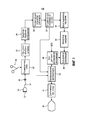
ФИГУРА 1 - блок-схема ультразвуковой системы, построенной согласно принципам настоящего изобретения.FIGURE 1 is a block diagram of an ultrasound system constructed in accordance with the principles of the present invention.
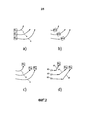
ФИГУРЫ 2a - 2d иллюстрируют движение точек в миокарде в процессе сокращения сердца.FIGURES 2a - 2d illustrate the movement of points in the myocardium during the contraction of the heart.
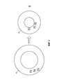
ФИГУРА 3 иллюстрирует движение точек в миокарде, наблюдаемое по короткой оси сердца.FIGURE 3 illustrates the movement of points in the myocardium, observed along the short axis of the heart.
ФИГУРА 4 - блок-схема алгоритма визуализации деформаций сердца согласно принципам настоящего изобретения.FIGURE 4 is a block diagram of an algorithm for visualizing heart deformities according to the principles of the present invention.
ФИГУРА 5 иллюстрирует кросс-корреляционные функции эхо-данных последовательных изображений сердца.FIGURE 5 illustrates the cross-correlation function of the echo data of sequential images of the heart.
ФИГУРА 6 графически иллюстрирует типовое кросс-корреляционное распределение спеклов, обусловленное движением сердца, в одном варианте осуществления настоящего изобретения.FIGURE 6 graphically illustrates a typical cross-correlation speckle distribution due to heart movement in one embodiment of the present invention.
Согласно принципам настоящего изобретения, описана ультразвуковая диагностическая система визуализации, способная осуществлять визуализацию сердца с высокой частотой кадров и вычислять деформацию в локализованных областях миокарда. Для каждого пикселя на изображении определяется параметр деформации, представляющий локальную деформацию, при этом эти пиксельные значения далее наносятся пространственно на анатомическое изображение. Карта деформаций затем приводится в соответствие с первым изображением следующего сердечного цикла и отображается в виде параметрического цветового наложения на кадры изображения следующего цикла изображений сердца. По мере того, как изменяются изображения с сокращением и расслаблением миокарда, цветовое наложение преобразуется, чтобы непрерывно соответствовать каждому изображению сердца. Таким образом, пользователю предоставляется отображение сердца в режиме реального времени, пространственное изменение его деформаций, а также соответствующие характеристики сократительной способности.According to the principles of the present invention, an ultrasound diagnostic imaging system is described that is capable of imaging a heart with a high frame rate and calculating deformation in localized regions of the myocardium. For each pixel in the image, a deformation parameter representing a local deformation is determined, with these pixel values being further spatially applied to the anatomical image. The deformation map is then aligned with the first image of the next cardiac cycle and displayed as a parametric color overlay on the image frames of the next cycle of heart images. As the images change with myocardial contraction and relaxation, the color overlay is converted to continuously match each image of the heart. Thus, the user is provided with a real-time display of the heart, a spatial change in its deformations, as well as the corresponding characteristics of contractility.
В некоторых аспектах настоящее изобретение предоставляет ультразвуковые диагностические системы визуализации для визуализации деформаций в режиме реального времени. Ультразвуковые системы могут включать в себя множество компонентов, таких как зонд для ультразвуковой визуализации. Зонд может включать в себя матричный датчик, осуществляющий сбор ультразвуковых эхо-сигналов. Системы могут включать в себя процессор обработки изображений. Процессор обработки изображений может соединяться с зондом для визуализации и выполнен с возможностью создания первой последовательности кадров изображения в режиме реального времени. Системы могут включать в себя калькулятор деформаций, соединенный с процессором обработки изображений. Калькулятор деформаций может быть выполнен с возможностью обработки данных кадра изображения для оценки деформации на протяжении последовательности кадров изображения. Системы могут включать в себя цветной картопостроитель. Системы могут быть выполнены с возможностью содержать процессоры, запоминающее устройство, а также другие структуры, которые могут быть запрограммированы, чтобы служить в качестве цветного картопостроителя. Цветной картопостроитель может быть выполнен с возможностью создания цветовой карты на основе значений деформаций. Системы могут включать в себя преобразователь цветовой карты. Системы могут включать в себя цветной картопостроитель. Системы могут быть выполнены с возможностью содержать процессоры, запоминающее устройство, а также другие структуры, которые могут быть запрограммированы, чтобы служить в качестве преобразователя цветовой карты. Преобразователь цветовой карты может реагировать на цветовую карту и новую последовательность кадров изображения, при этом выполнен с возможностью преобразования цветовой карты под кадр изображения новой последовательности, тем самым генерируя преобразованную цветовую карту. Системы могут также содержать дисплей, отображающий кадр изображения в сочетании с преобразованной цветовой картой.In some aspects, the present invention provides ultrasound diagnostic imaging systems for real-time strain imaging. Ultrasound systems can include many components, such as a probe for ultrasound imaging. The probe may include an array sensor collecting ultrasonic echoes. Systems may include an image processing processor. The image processor can be connected to the probe for visualization and is configured to create the first sequence of image frames in real time. Systems may include a strain calculator coupled to an image processing processor. The strain calculator may be configured to process image frame data to evaluate strain over a sequence of image frames. Systems may include a color chart maker. Systems can be configured to include processors, a storage device, as well as other structures that can be programmed to serve as color mappers. A color mapper can be configured to create a color map based on strain values. Systems may include a color map converter. Systems may include a color chart maker. Systems can be configured to include processors, a storage device, as well as other structures that can be programmed to serve as a color map converter. The color map converter can respond to a color map and a new sequence of image frames, while being configured to convert the color map to an image frame of a new sequence, thereby generating a converted color map. Systems may also include a display displaying an image frame in combination with a converted color map.
В некоторых вариантах осуществления кадры изображения могут включать в себя кадры изображения сердца. Первая последовательность кадров изображения может быть получена в течение первого сердечного цикла, а новая последовательность кадров изображения может быть получена в течение последующего сердечного цикла. Системы могут включать в себя запоминающее устройство для кадров, соединенное с процессором обработки изображений, которое хранит последовательности кадров изображения.In some embodiments, image frames may include heart image frames. The first sequence of image frames can be obtained during the first cardiac cycle, and a new sequence of image frames can be obtained during the subsequent cardiac cycle. Systems may include a frame memory coupled to an image processing processor that stores sequences of image frames.
В определенных вариантах осуществления системы могут включать в себя устройство для оценки смещений. Системы могут включать в себя цветной картопостроитель. Системы могут быть выполнены с возможностью содержать процессоры, запоминающее устройство, а также другие структуры, которые могут быть запрограммированы, чтобы служить в качестве устройства для оценки смещений и цветного картопостроителя. Устройство для оценки смещений может реагировать на последовательность кадров изображения и может быть выполнено с возможностью оценки смещения тканей на протяжении последовательности кадров изображения. Устройство для оценки смещений может включать в себя кросс-коррелятор смещений, оценивающий смещения путем кросс-корреляции эхо-данных, а также интегратор смещений, рассчитывающий интегральные значения смещений по Лагранжу.In certain embodiments, systems may include an apparatus for estimating displacements. Systems may include a color chart maker. Systems can be configured to include processors, a storage device, as well as other structures that can be programmed to serve as a device for estimating offsets and a color mapper. A device for estimating displacements may respond to a sequence of image frames and may be configured to evaluate a displacement of tissues throughout a sequence of image frames. A device for estimating displacements may include a cross-correlator of displacements, which estimates the displacements by cross-correlation of the echo data, as well as an integrator of displacements, which calculates the integral values of the displacements according to Lagrange.
В некоторых вариантах осуществления, системы могут включать в себя устройство для отслеживания спеклов, идентифицирующее смещение тканей. Системы могут включать в себя цветной картопостроитель. Системы могут быть выполнены с возможностью содержать процессоры, запоминающее устройство, а также другие структуры, которые могут быть запрограммированы, чтобы выполнять функции устройства для отслеживания спеклов и цветного картопостроителя. В определенных вариантах осуществления системы могут соединяться с ЭКГ-датчиком, распознающим волновую форму ЭКГ пациента. Системы могут дополнительно включать в себя формирователь пучка, соединенный с матричным датчиком и выполняющий функции по получению последовательностей кадров изображения в привязке к волновой форме ЭКГ.In some embodiments, systems may include a speckle tracking device that identifies tissue displacement. Systems may include a color chart maker. Systems can be configured to include processors, a storage device, as well as other structures that can be programmed to function as a speckle tracking device and color chart maker. In certain embodiments, the systems may be coupled to an ECG sensor recognizing the waveform of the patient's ECG. The systems may further include a beam former connected to the matrix sensor and performing the functions of acquiring sequences of image frames in conjunction with the waveform of the ECG.
Обратимся сначала к ФИГУРЕ 1, на которой ультразвуковая система, построенная согласно принципам настоящего изобретения, показана в форме блок-схемы. Зонд 10 имеет матрицу преобразовательных элементов 12, сканирующих область тела перед матрицей. Матрица может представлять собой одномерную или двумерную матрицу для 2D- или 3D-сканирования. Обычно в кардиологии матричный датчик работает в виде фазированной решетки. Зонд управляется формирователем 20 пучка, который управляет моментами подачи импульсов и обрабатывает полученные эхо-сигналы. Зонд 10 соединен с основной ультразвуковой системой с помощью кабеля 14 зонда и переключателя 16 приема/передачи, предохраняющего чувствительную электронику формирователя пучка в процессе передачи высокого напряжения. Формирователь пучка осуществляет задержку и объединяет сигналы, полученные от преобразовательных элементов, для формирования когерентных эхо-сигналов из точек в поле изображения. Эхо-сигналы поступают в процессор 22 обработки сигналов, который усиливает сигналы путем фильтрации и выдает распознанные эхо-сигналы. Обработанные эхо-сигналы далее преобразуются в пространственное изображение требуемого формата с помощью процессора 24 обработки изображений. Последовательно созданные кадры изображения хранятся в запоминающем устройстве 30 для кадров.We turn first to FIGURE 1, in which an ultrasound system constructed in accordance with the principles of the present invention is shown in block diagram form. The
Поскольку невозможно определить напряжение в миокарде напрямую с помощью ультразвука, т.е. силы, прикладываемой сердечной мышцей, влияние такой силы оценивают путем измерения стрейна, т.е. деформации сердца, порождаемой таким сократительным напряжением. Процесс измерения деформаций начинается с отслеживания движения миокарда при его сокращении. Поскольку ультразвук создает когерентные сигналы, проявляется феномен, именуемый спеклом. Пока зонд остается неподвижным, спекл-паттерн сохраняется от одного кадра изображения до следующего за ним. Детализированный спекл-паттерн отслеживается устройством 32 для отслеживания спеклов, которое тем самым сопровождает малые области ткани миокарда путем сопровождения изменения положения их спекл-паттерна от одного кадра изображения до следующего за ним. Поскольку изменение интенсивности эхо-сигналов, обусловленное спекл-структурой, находится на очень низком уровне, а значит, подвержено маскировке шумом, система по ФИГУРЕ 1 оценивает смещения спекл-паттерна от одного изображения до следующего за ним с помощью кросс-корреляции. Эхо последовательных кадров изображения подвергаются кросс-корреляции кросс-коррелятором 34 смещений, чтобы определить местоположение пика кросс-корреляционной функции. Типовая кросс-корреляционная функция показана на ФИГУРЕ 6. ФИГУРА 7 иллюстрирует одну кросс-корреляционную функцию 52, полученную из кросс-корреляции первого и второго последовательных кадров изображения, а также вторую кросс-корреляционную функцию 54, полученную из кросс-корреляции второго и следующего за ним последовательных кадров изображения. Как можно видеть, между пиками этих двух функций имеется временной сдвиг d. Этот временной сдвиг d представляет собой смещение ткани в последовательности изображений от одного кадра до следующего за ним. Поскольку этот сигнал временного сдвига подвержен шуму, смещения на множестве последовательных кадров интегрируются интегратором 36 смещений. Предпочтительно используется интегрирование по Лагранжу (Lagrangian integration) для получения единственного значения для каждой точки в миокарде, представляющего смещения на множестве последовательных кадров. Поскольку движение сердца является циклическим, а значит, возвращается к своей исходной точке в каждом сердечном цикле (сердце на кадре 1 занимает то же положение, что и на последнем кадре N), можно получить две независимые оценки для смещения на фазах сокращения и расслабления. Например, мгновенные смещения интегрируются вперед по времени от кадра 1 до M (обозначено I1-M) и назад по времени от кадра N до M (обозначено IM-N). Следует отметить, что кадр M соответствует конечной систоле; это фаза сердечного цикла, на которой деформации должны быть максимальными. Интегрированные смещения далее усредняются, чтобы получить сводную карту смещений, интегрированных по Лагранжу (Lagrangian integrated composite displacement map): IG=(I1-M+IM-N)/2. Интегрированные смещения далее используются калькулятором 38 деформаций для получения пространственных производных, представляющих собой пространственные значения деформаций для каждого местоположения пикселя. Взвешенное сочетание значений номинальной и сдвиговой деформаций используется для создания параметрического изображения. Один из примеров такого сочетания: (0.5Eyy +0,25Exy +0,25Exx), где Exx - деформация, перпендикулярная A-линии, Eyy - деформация вдоль A-линии, а Exy - сдвиговая деформация, полученная из аксиальных смещений. Это является мерой поворота. Данные значения деформаций далее наносятся в виде цветовых значений на двумерную или трехмерную цветовую карту блоком 40 цветового картирования деформаций. Цветовая карта пространственно соответствует миокарду, поскольку она появляется на кадрах изображения, на которых значения деформаций были рассчитаны. Цветовая карта может отображаться в виде статической цветовой карты деформации для сердечного цикла, для которого были рассчитаны значения деформаций.Since it is impossible to determine the voltage in the myocardium directly using ultrasound, i.e. the force exerted by the heart muscle, the effect of such a force is evaluated by measuring strain, i.e. heart deformation caused by such contractile stress. The process of measuring deformations begins with tracking the movement of the myocardium during its reduction. Since ultrasound produces coherent signals, a phenomenon called speckle appears. As long as the probe remains stationary, the speckle pattern is retained from one image frame to the next after it. A detailed speckle pattern is monitored by a
Согласно принципам настоящего изобретения, цветовая карта деформаций хранится в блоке 40 цветового картирования деформаций, при этом кадры получают на последующем сердечном цикле. Предпочтительно кадры каждого сердечного цикла получают на известных фазах сердечного цикла в привязке к R-волне ЭКГ-сигнала. Как известно, электроды 26 для физиологического исследования прикрепляют к телу пациента в процессе сканирования для получения волновой формы ЭКГ, при этом моменты времени получения кадров изображения, таким образом, могут быть привязаны к моментам проявления R-волны ЭКГ-сигнала. Когда образуется R-волна последующего сигнала сердца, она запускает блок 40 цветового картирования деформаций для соединения цветовой карты с преобразователем 42 цветовой карты. Преобразователь цветовой карты получает кадр изображения, созданный в течение нового сердечного цикла, а также в качестве опции может получать пространственную информацию об отслеженном спекле в новом изображении из устройства 32 для отслеживания спеклов. Преобразователь цветовой карты далее преобразует или приводит в соответствие цветовую карту из предшествующего сердечного цикла с изображением сердца нового сердечного цикла. Когда цветовая карта, таким образом, пространственно совмещена с миокардом в новом кадре изображения, преобразованная цветовая карта и новый кадр изображения поступают в дисплейный процессор, где цветовая карта используется в качестве цветового наложения на кадр изображения. Новый кадр изображения и его цветовое наложение преобразованной цветовой карты далее отображаются на дисплее 50.According to the principles of the present invention, the strain color map is stored in the strain
По мере получения последовательных кадров изображения нового сердечного цикла они поступают в преобразователь 42 цветовой карты, при этом цветовая карта, созданная в течение предыдущего сердечного цикла, преобразуется или приводится в соответствие с миокардом на каждом изображении. Цветовая карта деформации миокард, таким образом, вписывается в границы миокарда на каждом изображении нового сердечного цикла. Каждая преобразованная цветовая карта затем отображается в виде цветового наложения, нанесенного поверх каждого последующего кадра изображения сердца нового сердечного цикла. Отображение в режиме реального времени кадров изображения нового сердечного цикла, таким образом, включает в себя согласованное цветовое наложение деформаций, которое тем самым отображает динамическую последовательность изображений в режиме реального времени характеристик деформации миокарда.As successive frames of the image of the new cardiac cycle are received, they enter the
В качестве опции, отслеженные спекл-значения (speckle values) каждого нового кадра изображения нового сердечного цикла могут использоваться преобразователем 42 цветовой карты для согласования значений деформаций цветовой карты с соответствующими местоположениями спеклов в каждом новом кадре изображения. Вместо преобразования цветовой карты в целом значения деформаций цветовой карты постоянно переустанавливаются, чтобы согласовываться с изменением соответствующих местоположений спеклов в каждом новом кадре изображения.As an option, the tracked speckle values of each new image frame of the new heart cycle can be used by the
Одновременно с продолжением отображения по данной методологии элементы 32-40 ультразвуковой системы осуществляют расчет значений деформаций на новом сердечном цикле, так что создается новая цветовая карта для нового сердечного цикла. Новая цветовая карта далее используется в качестве нового преобразованного цветового наложения для следующего сердечного цикла.Simultaneously with the continuation of the mapping according to this methodology, elements 32-40 of the ultrasound system calculate the strain values on the new heart cycle, so that a new color map is created for the new heart cycle. The new color map is then used as a new converted color overlay for the next cardiac cycle.
ФИГУРА 2 иллюстрирует, как отдельные точки миокарда могут перемещаться в процессе сокращения сердца и как это перемещение проявляется в ультразвуковых изображениях. На ФИГУРЕ 2a) показаны три точки в миокарде, а именно MyA, MyB и MyC, которые в процессе сердечного сокращения перемещаются вдоль соответствующих траекторий A, B и C. После начального периода времени, т.е. отрезка времени между последовательными кадрами изображения в данном примере, эти точки в миокарде стянулись в положения вдоль траекторий A, B и C, как показано на ФИГУРЕ 2b). После следующего межкадрового периода времени точки миокарда переместились дополнительно в положения, показанные на ФИГУРЕ 2c). Непрерывное движение при данном перемещении теперь фиксируется с помощью ультразвуковой визуализации, однако только местоположения точек миокарда в момент времени, в который получен кадр изображения. Таким образом, движение, фиксируемое ультразвуковой визуализацией, представляет собой последовательность прямолинейных смещений 60, как показано на ФИГУРЕ 2d). Это смещение, если его изобразить в более широком контексте сокращения миокарда, принимает вид, показанный на ФИГУРЕ 3. На этом чертеже показан вид миокарда по короткой оси, где срез миокарда через сердце имеет вид тороида. В исходном положении точек миокарда на ФИГУРЕ 2a) эти точки сгруппированы так, как показано на левой стороне ФИГУРЫ 3. После того как сердце совершило сокращение, эти точки переместились внутрь и стали ближе друг к другу, как показано на правой стороне ФИГУРЫ 3. В типичном здоровом сердце можно ожидать, что точки мышцы миокарда перемещаются на 20% ближе друг к другу на фазе сокращения сердца. Данное смещение каждой точки миокарда представлено единственным значением после интегрирования по Лагранжу и вычисления деформаций в ультразвуковой системе. Конечные значения деформаций далее используются в пространственно упорядоченной цветовой карте значений деформаций.FIGURE 2 illustrates how individual points of the myocardium can move during the contraction of the heart and how this movement manifests itself in ultrasound images. FIGURE 2a) shows three points in the myocardium, namely, My A , My B and My C , which during the process of cardiac contraction move along the corresponding trajectories A, B and C. After the initial period of time, i.e. the time interval between consecutive image frames in this example, these points in the myocardium are pulled together to positions along trajectories A, B and C, as shown in FIGURE 2b). After the next inter-frame time period, the myocardial points moved additionally to the positions shown in FIGURE 2c). Continuous movement at this movement is now recorded using ultrasound imaging, but only the location of the myocardial points at the point in time at which the image frame was received. Thus, the motion recorded by ultrasound imaging is a sequence of
В некоторых аспектах настоящее изобретение включает в себя способы создания ультразвуковых изображений деформаций в режиме реального времени. Способы могут включать в себя получение кадров эхо-данных изображения, оценку смещения тканей между полученными кадрами из эхо-данных изображения, расчет значений деформаций из смещений, формирование цветовой карты значений деформаций, получение дополнительных кадров эхо-данных изображения, преобразование цветовой карты под дополнительные кадры, отображение дополнительных кадров в сочетании с преобразованными цветовыми картами, сгенерированными путем преобразования цветовой карты под дополнительные кадры.In some aspects, the present invention includes methods for creating real-time ultrasound images of deformations. Methods may include obtaining frames of image echo data, estimating tissue displacement between received frames from image echo data, calculating strain values from displacements, generating a color map of strain values, obtaining additional frames of image echo data, converting a color map to additional frames , display of additional frames in combination with converted color maps generated by converting a color map to additional frames.
В некоторых аспектах получение кадров эхо-данных изображения может включать в себя получение кадров изображения сердца. Оценка смещения тканей может включать в себя осуществление спекл-трекинга. Спекл-трекинг может включать в себя оценку смещений с помощью кросс-корреляции, а также выполнение интегрирования смещений по Лагранжу. В определенных вариантах осуществления способы могут включать в себя получение волновой формы ЭКГ пациента, а также получение кадров эхо-данных изображения в привязке к моментам времени, отображенным на волновой форме ЭКГ. In some aspects, acquiring frames of image echo data may include obtaining frames of an image of the heart. Assessment of tissue displacement may include speckle tracking. Speckle tracking can include the estimation of offsets using cross-correlation, as well as the integration of Lagrange offsets. In certain embodiments, the methods may include acquiring a patient’s ECG waveform, as well as acquiring image echo frames in relation to points in time displayed on the ECG waveform.
Преобразование цветовой карты может включать в себя согласование цветовой карты с границами миокарда в каждом из дополнительных кадров. Преобразование цветовой карты может включать в себя согласование цветовой карты со спекл-паттерном в каждом из дополнительных кадров.Converting a color map may include matching the color map with the borders of the myocardium in each of the additional frames. Converting a color map may include matching the color map with a speckle pattern in each of the additional frames.
Способ по настоящему изобретению изображен на блок-схеме алгоритма по ФИГУРЕ 4. Первый этап 102 заключается в сборе эхо-данных с высокой частотой кадров. Чем выше частота кадров изображения, тем меньше приращения смещений точек в миокарде (см ФИГУРУ 2d)). Предпочтительно кадры изображения получают с частотой 100 Гц или более. Повышенная частота кадров обеспечивает улучшение характеристик при использовании 2D-изображений, при которых происходит перемещение точек миокарда за пределы плоскости изображения. Повышенная частота кадров придает уверенность, что точка миокарда дискретизируется, по меньшей мере, дважды, прежде чем она покинет плоскость изображения, что позволяет оценить деформацию для этой точки. Далее на этапе 104 начинается проведение спекл-трекинга путем оценки смещений структур на кадре изображения, таких как спекл, с помощью кросс-корреляции. На этапе 106 выполняется интегрирование смещений по Лагранжу. На этапе 106 вычисляется деформация в виде пространственных производных смещения. Значения деформаций далее используются для формирования цветовой карты на этапе 108.The method of the present invention is shown in the flowchart of FIGURE 4. The
На этапе 110 получают кадры изображения следующего сокращения сердца. Цветовая карта после этого преобразуется, чтобы соответствовать миокарду на кадрах изображения следующего сокращения сердца, и отображается в виде цветового наложения на миокард в новом изображении. Процесс преобразования и наложения продолжается на всем протяжении следующего сокращения сердца, при этом одновременно выполняется обработка кадров изображения следующего сокращения сердца для формирования цветовой карты, используемой в качестве преобразованного наложения с кадрами изображения следующего сердечного цикла.At 110, image frames of the next heartbeat are obtained. The color map is then converted to fit the myocardium on the image frames of the next heart beat, and displayed as a color overlay on the myocardium in the new image. The conversion and overlay process continues throughout the next heartbeat, while simultaneously processing the image frames of the next heartbeat to form a color map used as a converted overlay with the image frames of the next heart cycle.
Следует понимать, что каждый блок изображенных блок-схем, а также сочетания блоков на изображениях блок-схемах, так же, как и любая часть систем и способов, раскрытых в настоящем описании, могут быть реализованы с помощью команд компьютерной программы. Эти программные команды могут выдаваться в процессор для создания аппаратной платформы, так что команды, выполняемые процессором, создают средство для реализации действий, указанных в блоке или блоках блок-схем, либо описанных для систем и способов, раскрытых в настоящем описании. Команды компьютерной программы могут выполняться процессором, чтобы обеспечить осуществление процессором ряда рабочих этапов с целью организации процесса, реализуемого компьютером. Команды компьютерной программы могут также обеспечить параллельное выполнение, по меньшей мере, некоторых рабочих этапов. Помимо этого, некоторые из этапов могут также осуществляться более чем на одном процессоре, например, в многопроцессорной компьютерной системе. Кроме того, один или несколько процессов могут также осуществляться одновременно с другими процессами или даже в иной последовательности, чем та, что проиллюстрирована, без отступления от объема или существа изобретения.It should be understood that each block of the shown block diagrams, as well as combinations of blocks in the images of the block diagrams, as well as any part of the systems and methods disclosed in the present description, can be implemented using computer program instructions. These program instructions can be issued to the processor to create a hardware platform, so that the instructions executed by the processor provide a means for implementing the actions indicated in the block or blocks of the flowcharts or described for the systems and methods disclosed in the present description. Computer program instructions may be executed by a processor to enable the processor to carry out a number of work steps in order to organize a process implemented by a computer. Computer program instructions may also provide concurrent execution of at least some work steps. In addition, some of the steps can also be carried out on more than one processor, for example, in a multiprocessor computer system. In addition, one or more processes can also be carried out simultaneously with other processes or even in a different sequence than that illustrated, without departing from the scope or essence of the invention.
Команды компьютерной программы могут храниться на любом пригодном машиночитаемом аппаратно-реализованном носителе, в частности RAM, ROM, EEPROM, флэш-ПЗУ или других запоминающих устройствах, CD-ROM, универсальных цифровых дисках (DVD) или других оптических ЗУ, магнитных кассетах, магнитной ленте, ЗУ на магнитных дисках или других магнитных ЗУ, либо любом другом носителе, который может использоваться для хранения требуемой информации и к которому может иметь доступ компьютерное устройство. Процессоры могут содержать аппаратное обеспечение, например, микропроцессоры, программируемые пользователем вентильные матрицы (FPGA), интегральные схемы и т.п.Computer program instructions can be stored on any suitable machine-readable hardware-implemented medium, in particular RAM, ROM, EEPROM, flash ROM or other storage devices, CD-ROMs, universal digital disks (DVDs) or other optical memories, magnetic tapes, magnetic tape , Memory on magnetic disks or other magnetic memory, or any other medium that can be used to store the required information and which can be accessed by a computer device. Processors may include hardware, for example, microprocessors, field programmable gate arrays (FPGAs), integrated circuits, and the like.
Claims (43)
Applications Claiming Priority (3)
| Application Number | Priority Date | Filing Date | Title |
|---|---|---|---|
| US201562109209P | 2015-01-29 | 2015-01-29 | |
| US62/109,209 | 2015-01-29 | ||
| PCT/IB2016/050308 WO2016120763A1 (en) | 2015-01-29 | 2016-01-22 | Evaluation of cardiac infarction by real time ultrasonic strain imaging |
Publications (3)
| Publication Number | Publication Date |
|---|---|
| RU2017130279A RU2017130279A (en) | 2019-03-01 |
| RU2017130279A3 RU2017130279A3 (en) | 2019-05-20 |
| RU2695475C2 true RU2695475C2 (en) | 2019-07-23 |
Family
ID=55299689
Family Applications (1)
| Application Number | Title | Priority Date | Filing Date |
|---|---|---|---|
| RU2017130279A RU2695475C2 (en) | 2015-01-29 | 2016-01-22 | Assessment of myocardial infraction by means of ultrasonic visualization of deformations in real time |
Country Status (6)
| Country | Link |
|---|---|
| US (2) | US11109832B2 (en) |
| EP (1) | EP3250131B1 (en) |
| JP (1) | JP6353608B2 (en) |
| CN (1) | CN107205725B (en) |
| RU (1) | RU2695475C2 (en) |
| WO (1) | WO2016120763A1 (en) |
Families Citing this family (3)
| Publication number | Priority date | Publication date | Assignee | Title |
|---|---|---|---|---|
| CN107205725B (en) * | 2015-01-29 | 2020-06-30 | 皇家飞利浦有限公司 | Assessment of myocardial infarction by real-time ultrasound strain imaging |
| GB201610269D0 (en) * | 2016-06-13 | 2016-07-27 | Isis Innovation | Image-based diagnostic systems |
| CN114515169B (en) * | 2021-12-31 | 2023-06-30 | 西安交通大学 | Multi-parameter imaging method and system for ultrasonic myocardial tissue |
Citations (4)
| Publication number | Priority date | Publication date | Assignee | Title |
|---|---|---|---|---|
| US20030083578A1 (en) * | 2001-09-21 | 2003-05-01 | Yasuhiko Abe | Ultrasound diagnostic apparatus, and image processing method |
| US20050288589A1 (en) * | 2004-06-25 | 2005-12-29 | Siemens Medical Solutions Usa, Inc. | Surface model parametric ultrasound imaging |
| RU2356499C1 (en) * | 2007-11-28 | 2009-05-27 | Государственное образовательное учреждение высшего профессионального образования Московская медицинская академия им. И.М. Сеченова Федерального агентства по здравоохранению и социальному развитию (ГОУВПО ММА им. И.М. Сеченова Росздрава) | Method of detecting risk group of diastolic aortic ventricle dysfunction in patients suffering from coronary heart disease |
| US20130286023A1 (en) * | 2006-05-05 | 2013-10-31 | General Electric Company | User interface and method for identifying related information displayed in an ultrasound system |
Family Cites Families (20)
| Publication number | Priority date | Publication date | Assignee | Title |
|---|---|---|---|---|
| US6749571B2 (en) * | 2002-09-19 | 2004-06-15 | Wisconsin Alumni Research Foundation | Method and apparatus for cardiac elastography |
| US6994673B2 (en) * | 2003-01-16 | 2006-02-07 | Ge Ultrasound Israel, Ltd | Method and apparatus for quantitative myocardial assessment |
| JP4795672B2 (en) * | 2004-11-16 | 2011-10-19 | 株式会社東芝 | Ultrasonic diagnostic equipment |
| US8150128B2 (en) * | 2006-08-30 | 2012-04-03 | The Trustees Of Columbia University In The City Of New York | Systems and method for composite elastography and wave imaging |
| EP2082261A2 (en) * | 2006-11-03 | 2009-07-29 | Koninklijke Philips Electronics N.V. | Dual path processing for optimal speckle tracking |
| JP5523681B2 (en) * | 2007-07-05 | 2014-06-18 | 株式会社東芝 | Medical image processing device |
| JP2009148421A (en) * | 2007-12-20 | 2009-07-09 | Toshiba Corp | Ultrasonic diagnostic apparatus and ultrasonic stress image acquisition method |
| JP5619347B2 (en) * | 2007-12-20 | 2014-11-05 | 東芝メディカルシステムズ株式会社 | Ultrasonic diagnostic apparatus, ultrasonic image analysis apparatus, and ultrasonic image analysis program |
| JP5259267B2 (en) | 2008-06-19 | 2013-08-07 | 株式会社東芝 | Ultrasonic diagnostic apparatus, ultrasonic image processing apparatus, and ultrasonic image processing program |
| US9089278B2 (en) * | 2008-07-10 | 2015-07-28 | Koninklijke Philips N.V. | Ultrasonic assessment of cardiac synchronicity and viability |
| JP5299961B2 (en) * | 2009-01-14 | 2013-09-25 | 東芝メディカルシステムズ株式会社 | Ultrasonic diagnostic apparatus, image processing apparatus, and control program for ultrasonic diagnostic apparatus |
| US8224053B2 (en) * | 2009-03-31 | 2012-07-17 | General Electric Company | Methods and systems for displaying quantitative segmental data in 4D rendering |
| US10321892B2 (en) | 2010-09-27 | 2019-06-18 | Siemens Medical Solutions Usa, Inc. | Computerized characterization of cardiac motion in medical diagnostic ultrasound |
| JP5944633B2 (en) * | 2011-02-25 | 2016-07-05 | 株式会社東芝 | Ultrasonic diagnostic apparatus, image processing apparatus, and program |
| CN103814384B (en) * | 2011-06-09 | 2017-08-18 | 香港科技大学 | Tracking based on image |
| CN102283679B (en) * | 2011-08-04 | 2014-05-21 | 中国科学院深圳先进技术研究院 | Ultrasonic imaging system for elasticity measurement and method for measuring elasticity of biological tissue |
| EP2827777A4 (en) * | 2012-03-23 | 2015-12-16 | Ultrasound Medical Devices Inc | Method and system for acquiring and analyzing multiple image data loops |
| JP5774560B2 (en) * | 2012-08-20 | 2015-09-09 | ジーイー・メディカル・システムズ・グローバル・テクノロジー・カンパニー・エルエルシー | Ultrasonic diagnostic apparatus and control program therefor |
| EP2782068A2 (en) * | 2013-03-22 | 2014-09-24 | Samsung Medison Co., Ltd. | Apparatus and method for providing elasticity information |
| CN107205725B (en) * | 2015-01-29 | 2020-06-30 | 皇家飞利浦有限公司 | Assessment of myocardial infarction by real-time ultrasound strain imaging |
-
2016
- 2016-01-22 CN CN201680007678.XA patent/CN107205725B/en active Active
- 2016-01-22 WO PCT/IB2016/050308 patent/WO2016120763A1/en active Application Filing
- 2016-01-22 US US15/545,748 patent/US11109832B2/en active Active
- 2016-01-22 RU RU2017130279A patent/RU2695475C2/en active
- 2016-01-22 JP JP2017538639A patent/JP6353608B2/en active Active
- 2016-01-22 EP EP16702806.7A patent/EP3250131B1/en active Active
-
2021
- 2021-07-19 US US17/378,978 patent/US11744543B2/en active Active
Patent Citations (4)
| Publication number | Priority date | Publication date | Assignee | Title |
|---|---|---|---|---|
| US20030083578A1 (en) * | 2001-09-21 | 2003-05-01 | Yasuhiko Abe | Ultrasound diagnostic apparatus, and image processing method |
| US20050288589A1 (en) * | 2004-06-25 | 2005-12-29 | Siemens Medical Solutions Usa, Inc. | Surface model parametric ultrasound imaging |
| US20130286023A1 (en) * | 2006-05-05 | 2013-10-31 | General Electric Company | User interface and method for identifying related information displayed in an ultrasound system |
| RU2356499C1 (en) * | 2007-11-28 | 2009-05-27 | Государственное образовательное учреждение высшего профессионального образования Московская медицинская академия им. И.М. Сеченова Федерального агентства по здравоохранению и социальному развитию (ГОУВПО ММА им. И.М. Сеченова Росздрава) | Method of detecting risk group of diastolic aortic ventricle dysfunction in patients suffering from coronary heart disease |
Also Published As
| Publication number | Publication date |
|---|---|
| WO2016120763A1 (en) | 2016-08-04 |
| CN107205725B (en) | 2020-06-30 |
| EP3250131A1 (en) | 2017-12-06 |
| RU2017130279A3 (en) | 2019-05-20 |
| JP2018506341A (en) | 2018-03-08 |
| US20220022843A1 (en) | 2022-01-27 |
| RU2017130279A (en) | 2019-03-01 |
| EP3250131B1 (en) | 2018-12-19 |
| US11744543B2 (en) | 2023-09-05 |
| CN107205725A (en) | 2017-09-26 |
| JP6353608B2 (en) | 2018-07-04 |
| US11109832B2 (en) | 2021-09-07 |
| US20180014812A1 (en) | 2018-01-18 |
Similar Documents
| Publication | Publication Date | Title |
|---|---|---|
| US6884216B2 (en) | Ultrasound diagnosis apparatus and ultrasound image display method and apparatus | |
| JP4733938B2 (en) | Ultrasonic diagnostic apparatus and ultrasonic image processing apparatus | |
| US9089278B2 (en) | Ultrasonic assessment of cardiac synchronicity and viability | |
| US8565504B2 (en) | Ultrasonic image processing apparatus and ultrasonic image processing method | |
| EP3092951B1 (en) | Method and apparatus for synthesizing medical images | |
| EP2529666B1 (en) | Ultrasonic diagnosis device and method used therefor to track measurement point | |
| JP2791255B2 (en) | Ultrasound color Doppler tomography | |
| US20090112088A1 (en) | Ultrasonic diagnostic apparatus, image data generating apparatus, ultrasonic diagnostic method and image data generating method | |
| US11744543B2 (en) | Evaluation of cardiac infarction by real time ultrasonic strain imaging | |
| EP1998682A1 (en) | Echocardiographic apparatus and method for analysis of cardiac dysfunction | |
| JP2001286474A (en) | Dynamic measurement of subject's parameter | |
| JPH07148165A (en) | Method and equipment for diagnosis of square average velocity of heart and cardiac muscle performance supervision | |
| JP4870449B2 (en) | Ultrasonic diagnostic apparatus and ultrasonic image processing method | |
| JP3187008B2 (en) | Ultrasound color Doppler tomography | |
| JP2007143606A (en) | Ultrasonograph | |
| JP2013233419A (en) | Ultrasonic diagnostic device, ultrasonic image processing device, and medical image diagnostic device | |
| JP2002177273A (en) | Ultrasonic diagnostic device | |
| US20130158403A1 (en) | Method for Obtaining a Three-Dimensional Velocity Measurement of a Tissue | |
| JP4921816B2 (en) | Ultrasonic diagnostic apparatus and control program therefor | |
| JP4795672B2 (en) | Ultrasonic diagnostic equipment | |
| JP2006523485A (en) | Heart wall strain imaging | |
| JP2008173387A (en) | Ultrasonic diagnostic apparatus, ultrasonic image processor, and ultrasonic image processing program | |
| US20230225698A1 (en) | 3-d ultrasound coronarography, a non-ionizing and non-invasive technology for multi-scale anatomical and functional imaging of coronary circulation | |
| Edvardsen | Matteo Cameli, Partho Sengupta, and | |
| JP2011104432A (en) | Ultrasonograph and ultrasonogram processor |