RU2695262C2 - Stenosis assessment - Google Patents
Stenosis assessment Download PDFInfo
- Publication number
- RU2695262C2 RU2695262C2 RU2017104807A RU2017104807A RU2695262C2 RU 2695262 C2 RU2695262 C2 RU 2695262C2 RU 2017104807 A RU2017104807 A RU 2017104807A RU 2017104807 A RU2017104807 A RU 2017104807A RU 2695262 C2 RU2695262 C2 RU 2695262C2
- Authority
- RU
- Russia
- Prior art keywords
- blood vessel
- stenosis
- site
- hemodynamic properties
- blood
- Prior art date
Links
Images
Classifications
-
- A—HUMAN NECESSITIES
- A61—MEDICAL OR VETERINARY SCIENCE; HYGIENE
- A61B—DIAGNOSIS; SURGERY; IDENTIFICATION
- A61B6/00—Apparatus for radiation diagnosis, e.g. combined with radiation therapy equipment
- A61B6/02—Devices for diagnosis sequentially in different planes; Stereoscopic radiation diagnosis
- A61B6/03—Computerised tomographs
- A61B6/032—Transmission computed tomography [CT]
-
- A—HUMAN NECESSITIES
- A61—MEDICAL OR VETERINARY SCIENCE; HYGIENE
- A61B—DIAGNOSIS; SURGERY; IDENTIFICATION
- A61B6/00—Apparatus for radiation diagnosis, e.g. combined with radiation therapy equipment
- A61B6/48—Diagnostic techniques
- A61B6/481—Diagnostic techniques involving the use of contrast agents
-
- A—HUMAN NECESSITIES
- A61—MEDICAL OR VETERINARY SCIENCE; HYGIENE
- A61B—DIAGNOSIS; SURGERY; IDENTIFICATION
- A61B6/00—Apparatus for radiation diagnosis, e.g. combined with radiation therapy equipment
- A61B6/48—Diagnostic techniques
- A61B6/486—Diagnostic techniques involving generating temporal series of image data
- A61B6/487—Diagnostic techniques involving generating temporal series of image data involving fluoroscopy
-
- A—HUMAN NECESSITIES
- A61—MEDICAL OR VETERINARY SCIENCE; HYGIENE
- A61B—DIAGNOSIS; SURGERY; IDENTIFICATION
- A61B6/00—Apparatus for radiation diagnosis, e.g. combined with radiation therapy equipment
- A61B6/50—Clinical applications
- A61B6/504—Clinical applications involving diagnosis of blood vessels, e.g. by angiography
-
- A—HUMAN NECESSITIES
- A61—MEDICAL OR VETERINARY SCIENCE; HYGIENE
- A61B—DIAGNOSIS; SURGERY; IDENTIFICATION
- A61B6/00—Apparatus for radiation diagnosis, e.g. combined with radiation therapy equipment
- A61B6/50—Clinical applications
- A61B6/507—Clinical applications involving determination of haemodynamic parameters, e.g. perfusion CT
-
- A—HUMAN NECESSITIES
- A61—MEDICAL OR VETERINARY SCIENCE; HYGIENE
- A61B—DIAGNOSIS; SURGERY; IDENTIFICATION
- A61B6/00—Apparatus for radiation diagnosis, e.g. combined with radiation therapy equipment
- A61B6/52—Devices using data or image processing specially adapted for radiation diagnosis
- A61B6/5211—Devices using data or image processing specially adapted for radiation diagnosis involving processing of medical diagnostic data
- A61B6/5217—Devices using data or image processing specially adapted for radiation diagnosis involving processing of medical diagnostic data extracting a diagnostic or physiological parameter from medical diagnostic data
-
- G—PHYSICS
- G06—COMPUTING; CALCULATING OR COUNTING
- G06T—IMAGE DATA PROCESSING OR GENERATION, IN GENERAL
- G06T7/00—Image analysis
- G06T7/0002—Inspection of images, e.g. flaw detection
- G06T7/0012—Biomedical image inspection
-
- G—PHYSICS
- G06—COMPUTING; CALCULATING OR COUNTING
- G06T—IMAGE DATA PROCESSING OR GENERATION, IN GENERAL
- G06T7/00—Image analysis
- G06T7/0002—Inspection of images, e.g. flaw detection
- G06T7/0012—Biomedical image inspection
- G06T7/0014—Biomedical image inspection using an image reference approach
- G06T7/0016—Biomedical image inspection using an image reference approach involving temporal comparison
-
- G—PHYSICS
- G06—COMPUTING; CALCULATING OR COUNTING
- G06T—IMAGE DATA PROCESSING OR GENERATION, IN GENERAL
- G06T7/00—Image analysis
- G06T7/60—Analysis of geometric attributes
- G06T7/68—Analysis of geometric attributes of symmetry
-
- G—PHYSICS
- G16—INFORMATION AND COMMUNICATION TECHNOLOGY [ICT] SPECIALLY ADAPTED FOR SPECIFIC APPLICATION FIELDS
- G16H—HEALTHCARE INFORMATICS, i.e. INFORMATION AND COMMUNICATION TECHNOLOGY [ICT] SPECIALLY ADAPTED FOR THE HANDLING OR PROCESSING OF MEDICAL OR HEALTHCARE DATA
- G16H50/00—ICT specially adapted for medical diagnosis, medical simulation or medical data mining; ICT specially adapted for detecting, monitoring or modelling epidemics or pandemics
- G16H50/50—ICT specially adapted for medical diagnosis, medical simulation or medical data mining; ICT specially adapted for detecting, monitoring or modelling epidemics or pandemics for simulation or modelling of medical disorders
-
- G—PHYSICS
- G06—COMPUTING; CALCULATING OR COUNTING
- G06T—IMAGE DATA PROCESSING OR GENERATION, IN GENERAL
- G06T2207/00—Indexing scheme for image analysis or image enhancement
- G06T2207/10—Image acquisition modality
- G06T2207/10072—Tomographic images
- G06T2207/10081—Computed x-ray tomography [CT]
-
- G—PHYSICS
- G06—COMPUTING; CALCULATING OR COUNTING
- G06T—IMAGE DATA PROCESSING OR GENERATION, IN GENERAL
- G06T2207/00—Indexing scheme for image analysis or image enhancement
- G06T2207/10—Image acquisition modality
- G06T2207/10116—X-ray image
-
- G—PHYSICS
- G06—COMPUTING; CALCULATING OR COUNTING
- G06T—IMAGE DATA PROCESSING OR GENERATION, IN GENERAL
- G06T2207/00—Indexing scheme for image analysis or image enhancement
- G06T2207/30—Subject of image; Context of image processing
- G06T2207/30004—Biomedical image processing
- G06T2207/30101—Blood vessel; Artery; Vein; Vascular
Landscapes
- Health & Medical Sciences (AREA)
- Engineering & Computer Science (AREA)
- Life Sciences & Earth Sciences (AREA)
- Medical Informatics (AREA)
- Physics & Mathematics (AREA)
- General Health & Medical Sciences (AREA)
- Radiology & Medical Imaging (AREA)
- Nuclear Medicine, Radiotherapy & Molecular Imaging (AREA)
- Public Health (AREA)
- Pathology (AREA)
- Biomedical Technology (AREA)
- Molecular Biology (AREA)
- Animal Behavior & Ethology (AREA)
- High Energy & Nuclear Physics (AREA)
- Biophysics (AREA)
- Heart & Thoracic Surgery (AREA)
- Optics & Photonics (AREA)
- Surgery (AREA)
- Veterinary Medicine (AREA)
- Theoretical Computer Science (AREA)
- Computer Vision & Pattern Recognition (AREA)
- General Physics & Mathematics (AREA)
- Quality & Reliability (AREA)
- Dentistry (AREA)
- Oral & Maxillofacial Surgery (AREA)
- Pulmonology (AREA)
- Vascular Medicine (AREA)
- Physiology (AREA)
- Geometry (AREA)
- Data Mining & Analysis (AREA)
- Databases & Information Systems (AREA)
- Epidemiology (AREA)
- Primary Health Care (AREA)
- Apparatus For Radiation Diagnosis (AREA)
Abstract
Description
Настоящее изобретение в целом относится к системе, способу и компьютерной программе для оценки стеноза кровеносного сосуда в теле.The present invention generally relates to a system, method and computer program for assessing stenosis of a blood vessel in the body.
УРОВЕНЬ ТЕХНИКИ ИЗОБРЕТЕНИЯBACKGROUND OF THE INVENTION
Стеноз кровеносного сосуда, препятствующий кровотоку в теле пациента, может вызвать серьезные проблемы со здоровьем пациента. Может потребоваться лечение, катетеризационное вмешательство или даже хирургическая операция, если степень тяжести стеноза высока и/или если стеноз имеет особо опасную локализацию. Поэтому крайне важно, чтобы врач имел достаточные и надежные доступные данные о локализации и степени тяжести стеноза.Blood vessel stenosis, which prevents blood flow in the patient’s body, can cause serious health problems for the patient. Treatment, catheterization, or even surgery may be necessary if the severity of the stenosis is high and / or if the stenosis has a particularly dangerous location. Therefore, it is imperative that the doctor has sufficient and reliable data available on the location and severity of stenosis.
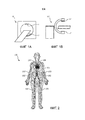
Степень стеноза является наиболее широко используемым параметром для установления диагноза. Гемодинамическая тяжесть стеноза может быть функционально оценена путем оценки давления внутри артерии (исследовано с помощью катетера) или измерений параметров потока, из которых можно определить фракционный резерв кровотока (ФРК), перепад давления или вызванное стенозом сопротивление. Эта инвазивная процедура требует точности и кропотливой работы, относящейся к процедуре, дорогостоящих катетеров, а также интервенционными рисками, поскольку через стеноз необходимо провести катетер. В качестве альтернативы, известны неинвазивные измерения с использованием и радиационной визуализации, например, с помощью рентгеновской радиационной визуализации, такой как, например, визуализация (смотри Фиг. 1a) с помощью компьютерной томографии (КТ), двумерная рентгеновская ангиография или (вращательная) рентгеновская визуализация с использованием С-образной рамы (смотри Фиг. 1b). С помощью этих методов генерируются изображения части тела, содержащей стенозированную артерию. Посредством вычислительных моделей, таких как моделирование методами вычислительной гидродинамики (ВГД), можно моделировать ФРК в различных местах стенозированной артерии, например, как описано в патенте США 8321150 В2. Другие функциональные параметры, такие как вызванное стенозом сопротивление или смоделированная функциональная оценка, также могут быть рассчитаны на основе ВГД моделей, таких как например, раскрытая в Michail I. Papafaklis и др., «Fast virtual functional assessment of intermediate coronary lesions using routine angiographic data and blood flow simulation in humans: comparison with pressure wire - fractional flow reserve», EuroIntervention 2014; Июль 2014 год.The degree of stenosis is the most widely used parameter for diagnosis. The hemodynamic severity of stenosis can be functionally assessed by evaluating the pressure inside the artery (examined using a catheter) or by measuring flow parameters from which to determine the fractional reserve of blood flow (PRF), pressure drop, or resistance caused by stenosis. This invasive procedure requires precision and painstaking work related to the procedure, expensive catheters, as well as interventional risks, since a catheter must be inserted through stenosis. Alternatively, non-invasive measurements using radiation imaging are known, for example, using x-ray radiation imaging, such as, for example, imaging (see Fig. 1a) using computed tomography (CT), two-dimensional x-ray angiography or (rotational) x-ray imaging using a C-frame (see Fig. 1b). Using these methods, images of the part of the body containing the stenotic artery are generated. Through computational models, such as computational fluid dynamics (IOP) modeling, PRK can be simulated at various locations in the stenotic artery, for example, as described in US Pat. No. 8,321,150 B2. Other functional parameters, such as stenosis-induced resistance or simulated functional assessment, can also be calculated based on IOP models, such as those described in Michail I. Papafaklis et al., “Fast virtual functional assessment of intermediate coronary lesions using routine angiographic data and blood flow simulation in humans: comparison with pressure wire - fractional flow reserve ", EuroIntervention 2014; July 2014
ВГД моделирование использует трехмерную сегментацию, полученную из КТ или рентгеновских изображений, и конкретные граничные условия на входах (например, до или после аорты) и выходах (например, отводы в микроциркуляторное русло). Граничные условия, как правило, оценивается из законов подобия, системных параметров, таких как кровяное давление, измеренное в конечностях, или объема мышцы/ткани, принимающей артериальный кровоток. Поскольку смоделированный ФРК чувствителен к этим граничным условиям, такой подход может быть ненадежным в некоторых случаях.IOP modeling uses three-dimensional segmentation obtained from CT or X-ray images, and specific boundary conditions at the inputs (for example, before or after the aorta) and outputs (for example, taps into the microvasculature). Boundary conditions are typically evaluated from similarity laws, systemic parameters, such as blood pressure measured in the limbs, or the volume of muscle / tissue receiving arterial blood flow. Since the simulated PRK is sensitive to these boundary conditions, this approach may be unreliable in some cases.
Также граничные условия, в известных ВГД моделях, как правило, оцениваются из предыдущих измерений давления/расхода или ВГД моделирований одного и того же, или даже другого, пациента. Однако они могут существенно отличаться от реальной ситуации у пациента, исследуемого в данный момент. Во-первых, условия могут изменяться у каждого пациента по времени. Например, локальные геометрические формы в сосудистой системе могут значительно отличаться между различными пациентами или возможно изменились с течением времени у того же самого пациента, возможно, даже (частично) из-за наличия стеноза. Кроме того, условия возможно были определены в разные моменты сердечного цикла и/или, возможно, была разница в частоте, силе и т.д. самого сердечного цикла, который может меняться.Also, the boundary conditions in the known IOP models are, as a rule, evaluated from previous pressure / flow measurements or IOP simulations of the same, or even another, patient. However, they may differ significantly from the actual situation of the patient being studied at the moment. First, the conditions may vary for each patient over time. For example, local geometric shapes in the vascular system may vary significantly between different patients or may have changed over time in the same patient, possibly even (partially) due to the presence of stenosis. In addition, the conditions may have been determined at different points in the cardiac cycle and / or there may have been a difference in frequency, strength, etc. the heart cycle itself, which may change.
СУЩНОСТЬ ИЗОБРЕТЕНИЯSUMMARY OF THE INVENTION
Варианты осуществления в соответствии с настоящим изобретением относятся к способу оценки стеноза кровеносного сосуда в теле по п. 1. Изобретение также относится к соответствующей системе и компьютерному программному продукту для системы для оценки тяжести стеноза кровеносного сосуда в теле.Embodiments in accordance with the present invention relate to a method for assessing stenosis of a blood vessel in the body according to
Преимущество настоящего изобретения состоит в том, что используются данные изображения второго, одновременно отображаемого и по существу симметричного кровеносного сосуда, для того, чтобы улучшить входные данные, которые предоставляются врачу для определения степени тяжести стеноза. Эти входные данные являются более надежными, так как они используют дополнительные данные изображения, которые не только очень схожи с данными стенозированного кровеносного сосуда, но они также снимаются в то же время и у того же самого пациента, тем самым устраняя вариабельность, имеющеюся у разных пациентов, или различия, связанные с изменениями по времени.An advantage of the present invention is that image data of a second, simultaneously displayed and substantially symmetrical blood vessel is used in order to improve the input that is provided to the physician to determine the severity of stenosis. This input is more reliable because it uses additional image data, which is not only very similar to stenotic blood vessel data, but it is also taken at the same time from the same patient, thereby eliminating the variability present in different patients , or differences associated with changes in time.
В одном из вариантов осуществления настоящего изобретения информация о симметрии между первым кровеносным сосудом и вторым кровеносным сосудом определяется посрезно, и участок второго кровеносного сосуда, соответствующего участку первого кровеносного сосуда, содержащего стеноз, выбирается на основании указанной определенной информации о симметрии. Это дает возможность улучшить сравнение, так как можно получить выбор участка второго кровеносного сосуда, который точнее соответствует стенозированной области в первом кровеносном сосуде.In one embodiment of the present invention, symmetry information between the first blood vessel and the second blood vessel is determined in-line, and the portion of the second blood vessel corresponding to the portion of the first blood vessel containing stenosis is selected based on the specified specific symmetry information. This makes it possible to improve the comparison, since it is possible to obtain a choice of the site of the second blood vessel, which more closely corresponds to the stenotic region in the first blood vessel.
В одном из вариантов осуществления настоящего изобретения гемодинамические свойства, относящиеся к участку первого кровеносного сосуда, содержащего стеноз, по меньшей мере, частично определяются из гемодинамических свойств, относящихся к участку второго кровеносного сосуда, соответствующего участку первого кровеносного сосуда, содержащего стеноз.In one embodiment of the present invention, the hemodynamic properties related to a portion of a first blood vessel containing stenosis are at least partially determined from the hemodynamic properties related to a portion of a second blood vessel corresponding to a portion of a first blood vessel containing stenosis.
Это особенно выгодно, так как введение гемодинамических свойств соответствующей «здоровой» артерии, по меньшей мере, частично, в определение гемодинамических свойств стенозированного кровеносного сосуда повышает точность определенных гемодинамических свойств стенозированного кровеносного сосуда, тем самым делая их более надежными. Кроме того, в случае, если оба сосуда имеют стеноз, можно оценить относительную тяжесть поражения между обоими стенозированными кровеносными сосудами.This is especially advantageous, since the introduction of the hemodynamic properties of the corresponding “healthy” artery, at least partially, into the determination of the hemodynamic properties of the stenotic blood vessel increases the accuracy of certain hemodynamic properties of the stenotic blood vessel, thereby making them more reliable. In addition, if both vessels have stenosis, the relative severity of the lesion between both stenosed blood vessels can be estimated.
В одном из вариантов осуществления настоящего изобретения одно или несколько гемодинамических свойств выбираются из группы, включающей в себя фракционный резерв кровотока, перепад кровяного давления и вызванное стенозом сопротивление. Они уже являются общеупотребительными и принятыми свойствами для оценки тяжести стеноза.In one embodiment of the present invention, one or more hemodynamic properties are selected from the group comprising a fractional reserve of blood flow, a drop in blood pressure, and resistance caused by stenosis. They are already common and accepted properties for assessing the severity of stenosis.
Еще один вариант осуществления настоящего изобретения относится к отображению определенных гемодинамических свойств, относящихся к участку первого кровеносного сосуда, содержащего стеноз. Это предоставляет врачу определенные гемодинамические свойства для оценки стеноза. Предпочтительно гемодинамические свойства отображаются по отношению к относительной длине сосуда. Это делает возможным более точное определение характеристик стеноза.Another variant implementation of the present invention relates to the display of certain hemodynamic properties related to the site of the first blood vessel containing stenosis. This provides the physician with certain hemodynamic properties for assessing stenosis. Preferably, the hemodynamic properties are displayed with respect to the relative length of the vessel. This makes it possible to more accurately determine the characteristics of stenosis.
Кроме того, могут быть отображены определенные гемодинамические свойства, относящиеся к участку второго кровеносного сосуда, соответствующего участку первого кровеносного сосуда, содержащего стеноз. Это предоставляет врачу дополнительные гемодинамические свойства очень похожего кровеносного сосуда, с которыми врач может сравнить эти свойства стенозированной артерии, что поможет ему в дальнейшем при оценке степени тяжести стеноза. Предпочтительно, чтобы определенные гемодинамические свойства, относящиеся к участку второго кровеносного сосуда, соответствующего участку первого кровеносного сосуда, содержащего стеноз, отображались зеркально. Это облегчает сравнение еще больше, так как оба кровеносных сосуда показываются в одинаковой ориентации. Это также даст возможность совмещать отображения обоих кровеносных сосудов, обеспечивая еще более сближенное визуальное сравнение между этими двумя кровеносными сосудами.In addition, certain hemodynamic properties relating to a portion of a second blood vessel corresponding to a portion of a first blood vessel containing stenosis can be displayed. This provides the doctor with additional hemodynamic properties of a very similar blood vessel with which the doctor can compare these properties of the stenotic artery, which will help him further in assessing the severity of stenosis. Preferably, certain hemodynamic properties relating to the area of the second blood vessel corresponding to the area of the first blood vessel containing stenosis are mirrored. This makes comparisons even easier, as both blood vessels appear in the same orientation. It will also make it possible to combine the displays of both blood vessels, providing an even closer visual comparison between the two blood vessels.
В дополнительном варианте осуществления настоящего изобретения стенозированная и соответствующая артерии изображаются с помощью неинвазивного средства визуализации, предпочтительно содержащего устройство формирования рентгеновского изображения, такое как устройство формирования рентгеновского изображения с помощью компьютерной томографии, устройство формирования рентгеновского изображения с помощью двумерной рентгеновской ангиографии или устройства формирования рентгеновского изображения с С-образной рамой. Использование неинвазивных средств визуализации устраняет необходимость полагаться на внутриартериальные, произведенные с помощью катетера измерения, недостатки которых были объяснены ранее. Рентгеновская визуализация доступна почти в каждой больнице и большинство методов пригодны для визуализации всего тела. В частности, компьютерная томография и рентгеновская визуализация с использованием С-образной рамы подходят для генерации 3D-изображений.In a further embodiment of the present invention, the stenotic and corresponding arteries are imaged using a non-invasive imaging device, preferably comprising an X-ray imaging device, such as a computed tomography X-ray imaging device, an X-ray imaging device using two-dimensional X-ray angiography, or an X-ray imaging device with C-shaped frame. The use of non-invasive imaging devices eliminates the need to rely on intra-arterial catheter measurements, the disadvantages of which have been explained previously. X-ray imaging is available in almost every hospital and most methods are suitable for whole-body imaging. In particular, computed tomography and X-ray imaging using a C-frame are suitable for generating 3D images.
В дополнительном варианте осуществления настоящего изобретения гемодинамическая модель, предпочтительно основанная на моделировании кровотока методами вычислительной гидродинамики, используется для определения гемодинамических свойств. Эти модели хорошо известны и пригодны для целей данного изобретения. Эти модели основаны на входных данных и в одном из вариантов осуществления настоящего изобретения эти входные данные предоставляются по данным, доступным для стенозированного кровеносного сосуда, а также, по меньшей мере, частично, по данным изображения другого, например, нестенозированного, по существу симметричного кровеносного сосуда. Это улучшает входные параметры и должно привести к лучшему моделированию стенозированной артерии. Это дает врачу более надежные входные данные для оценки тяжести стеноза. Другой кровеносный сосуд может также иметь стеноз. С помощью настоящего изобретения врач получает доступ к относительной тяжести поражения между обоими стенозированными кровеносными сосудами.In an additional embodiment of the present invention, a hemodynamic model, preferably based on modeling of blood flow using computational fluid dynamics methods, is used to determine hemodynamic properties. These models are well known and suitable for the purposes of this invention. These models are based on input data and, in one embodiment of the present invention, this input data is provided from data available for a stenotic blood vessel, as well as at least partially from image data of another, for example, non-stenotic, substantially symmetrical blood vessel . This improves input parameters and should lead to better modeling of stenosed artery. This gives the doctor a more reliable input for assessing the severity of stenosis. Another blood vessel may also have stenosis. Using the present invention, the physician gains access to the relative severity of the lesion between both stenotic blood vessels.
Настоящее изобретение особенно подходит для оценки стеноза в кровеносных сосудах ног, кровеносных сосудах рук, сонных артериях и подвздошных артериях, а также, конечно, подходит для других кровеносных сосудов, для которых фактически доступен симметричный аналог.The present invention is particularly suitable for assessing stenosis in the blood vessels of the legs, blood vessels of the hands, carotid arteries and iliac arteries, and also, of course, is suitable for other blood vessels for which a symmetrical analogue is actually available.
Кроме того, дополнительные аспекты и варианты осуществления настоящего изобретения будут понятны специалистам в данной области после прочтения и восприняты из следующего подробного описания. Многочисленные дополнительные преимущества и выгоды станут очевидными для специалистов в данной области после прочтения приведенного ниже подробного описания предпочтительных вариантов осуществления.In addition, further aspects and embodiments of the present invention will be apparent to those skilled in the art upon reading, and are taken from the following detailed description. Numerous additional advantages and benefits will become apparent to those skilled in the art upon reading the following detailed description of preferred embodiments.
КРАТКОЕ ОПИСАНИЕ ЧЕРТЕЖЕЙBRIEF DESCRIPTION OF THE DRAWINGS
Настоящее изобретение иллюстрируется чертежами, на которыхThe present invention is illustrated by drawings, in which
на Фиг. 1 показано схематическое представление устройства формирования изображения (Фиг. 1a) компьютерной томографии и устройства формирования рентгеновского изображения с С-образной рамой (Фиг. 1b);in FIG. 1 shows a schematic representation of an image forming apparatus (FIG. 1a) of computed tomography and a C-shaped X-ray image forming apparatus (FIG. 1b);
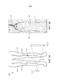
на Фиг. 2 показано схематическое изображение расположений симметричных кровеносных сосудов, которые могут быть оценены в соответствии с настоящим изобретением;in FIG. 2 is a schematic illustration of symmetrical blood vessel locations that can be evaluated in accordance with the present invention;
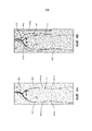
на Фиг. 3 показано схематическое представление (Фиг. 3a) и изображение, сгенерированное с помощью неинвазивной визуализации (Фиг. 3b) нижней части человеческого тела;in FIG. 3 shows a schematic representation (Fig. 3a) and an image generated by non-invasive imaging (Fig. 3b) of the lower part of the human body;
на Фиг. 4 показаны два варианта осуществления (Фиг. 4a и 4b) из вариантов осуществления отображенных гемодинамических свойств; иin FIG. 4 shows two embodiments (Figs. 4a and 4b) of the embodiments of the displayed hemodynamic properties; and
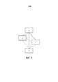
на Фиг. 5 показан схематический общий вид способа оценки стеноза кровеносного сосуда в теле в соответствии с настоящим изобретением;in FIG. 5 shows a schematic general view of a method for assessing stenosis of a blood vessel in a body in accordance with the present invention;
Изобретение может принимать форму в виде различных компонентов и вариантов сочетания компонентов, а также в виде различных операций процесса и компоновок операций процесса. Чертежи приведены только с целью иллюстрации предпочтительных вариантов осуществления и не должны толковаться как ограничивающие данное изобретение. Для лучшей визуализации некоторые признаки могут быть опущены или размеры могут быть не в масштабе.The invention may take the form in the form of various components and combinations of components, as well as in the form of various process operations and process operation arrangements. The drawings are provided for the purpose of illustrating preferred embodiments only and should not be construed as limiting the invention. For better visualization, some features may be omitted or dimensions may not be to scale.
ПОДРОБНОЕ ОПИСАНИЕ ВАРИАНТОВ ОСУЩЕСТВЛЕНИЯDETAILED DESCRIPTION OF EMBODIMENTS
В контексте настоящего изобретения термин стеноз может представлять любое сужение кровеносного сосуда, в том числе повреждение, сдавление сосуда, (более или менее) стабильный тромб и т.п. Термин кровеносный сосуд охватывает все части сосудистой системы человеческого тела, которые переносят кровь, в том числе артерии, вены и капилляры; хотя на практике настоящее изобретение, скорее всего, будет наиболее подходящим и надежным для более крупных артерий и вен.In the context of the present invention, the term stenosis can be any narrowing of a blood vessel, including damage, compression of the vessel, (more or less) stable thrombus, etc. The term blood vessel encompasses all parts of the vascular system of the human body that carry blood, including arteries, veins, and capillaries; although in practice the present invention is likely to be most suitable and reliable for larger arteries and veins.
Изобретение может быть особенно полезным по отношению к кровеносным сосудам ног (таким как бедренные артерии) 101, 101ʹ, подвздошным артериям 102, 102', кровеносным сосудам рук (таким как плечевые артерии) 103, 103' и сонным артериям 104, 104 ', местоположения которых в теле 100 показаны на Фиг. 2. Очевидно, что это не ограничивающий перечень, изобретение также подходит для других кровеносных сосудов, среди которых существуют по существу симметричные пары (например, почечные артерии, яремные вены и т.д.). Но настоящее изобретение будет также потенциально пригодно для других, более мелких кровеносных сосудов, при условии наличия по существу симметричного второго кровеносного сосуда, который можно использовать. Изобретение в основном иллюстрируются с использованием артерий ног в качестве неограничивающего примера, но равным образом для специалиста не вызовет затруднений адаптация граничных условий и моделей настоящего изобретения для других в кровеносных сосудах тела.The invention may be particularly useful with respect to the blood vessels of the legs (such as the femoral arteries) 101, 101ʹ, the
Изобретение дополнительно поясняется с использованием радиационной визуализации, в первую очередь рентгеновской визуализации, и, в частности, компьютерной томографии, двумерной рентгеновской ангиографии или (вращательной) визуализации с использованием С-образной рамы, где используется источник излучения 11, 11', испускающий излучение через область исследования в направлении детектора 12, 12' излучения. Объект, подлежащий визуализации, такой как тело, содержащее стенозированный кровеносный сосуд, перемещается через область обследования. Испускаемое излучение ослабляется в различных слоях различными частями тела внутри тела и после обнаружения оно обрабатывается и реконструируется в срез изображения облученного участка тела. Это повторяется до тех пор, пока тело или, по меньшей мере, часть тела, представляющая интерес, полностью не пройдет через область исследования. В результате серии срезов изображения могут быть объединены с тем, чтобы построить трехмерное изображение тела и его внутренних жестких и мягких частей тела. Изобретение, конечно, не ограничивается рентгеновской визуализацией, также можно использовать другие известные способы радиационной визуализации, такие как магнитно-резонансная визуализация, ультразвуковая визуализация и другие, известные в данной области, или их сочетания. Более того, изобретение также пригодно для использования со способами нерадиационной визуализации, таким как внутриартериальная визуализация, как оптическая когерентная томография (ОКТ) или внутрисосудистое ультразвуковое исследование (ВСУЗИ). Хотя преимущества неинвазивной визуализации могут быть потеряны, другие преимущества изобретения будут также действительны для неинвазивной визуализации.The invention is further illustrated using radiation imaging, primarily x-ray imaging, and, in particular, computed tomography, two-dimensional x-ray angiography or (rotational) imaging using a C-shaped frame, which uses a
На Фигуре 3a изображено тело 100 пациента, которое перемещается через область 13 исследования между источником излучения 11, 11' и детектором 12, 12' излучения устройства формирования рентгеновского изображения. Представляющей интерес областью является левая нога 110 тела 100 пациента, так как главная артерия 101 левой ноги содержит стеноз 111, чье точное местоположение и степень тяжести и должны быть оценены. Область 13 исследования достаточно большая, чтобы вместить как левую ногу 110, так и правую ногу 110', которые, следовательно, обе отображаются одновременно. Правая нога 110' содержит главную артерию 101', которая, по существу, симметрична главной артерии 101 правой ноги 110. Термин по существу симметрична следует понимать в свете данного изобретения, как симметрична, если смотреть на это широко, без учета любых очевидных различий, обусловленных человеческим телом, которое никогда не бывает полностью симметричным (например, различия в длине ног, толщине, распределении мышц, углам через ногу и т.д.). Очевидно, что на микроскопическом уровне, какие-либо боковые ответвления также не могут возникать в одних и тех же местоположениях вдоль главной артерии. По сути, главные ответвления обеих артерий должны более или менее перекрываться при наложении друг на друга. Если никаких серьезных отклонений между двумя артерий нет, особенно в области, представляющей интерес, то симметрия является достаточной для цели данного изобретения.Figure 3a shows a patient’s
В случае, если пациент хорошо расположен на кушетке и имеет довольно симметричные ноги, симметрия информация о ноге может быть дополнительно уточнена путем сравнения информации посрезно. Она также может включать в себя опознавательную точку, основанную на жесткой фиксации, причем указанные опознавательные точки могут быть костными опознавательными точками, например, головкой бедренной кости или коленом. В случае, если позиционирование кушетки пациента не является оптимальным, то для коррекции этого можно использовать угол тазовой кости по отношению к осевому срезу. В дополнение к жесткой фиксации для коррекции остальных нарушений симметрии ткани и сосудов можно использовать эластичную фиксацию.In the event that the patient is well located on the couch and has fairly symmetrical legs, the symmetry of the leg information can be further refined by comparing the information in sections. It may also include an identification point based on rigid fixation, wherein said identification points may be bone identification points, for example, a femoral head or a knee. If the positioning of the patient’s couch is not optimal, then to correct this, you can use the angle of the pelvic bone with respect to the axial section. In addition to rigid fixation, elastic fixation can be used to correct other symmetry disorders of the tissue and blood vessels.
После того, как нижняя часть тела пациента прошла через область исследования строится изображение, содержащее ноги 110, 110'. Это может быть трехмерным изображением и могут быть показаны все внутренние части тела. Альтернативно может быть показано двухмерное изображение и/или изображение, высвечивающее только определенные части тела, такие как артериальная система. На Фигуре 3b показано такое реконструированное изображение. Это двухмерное изображение, высвечивающее артериальную систему, которая выбрана для ясности, чтобы проиллюстрировать настоящее изобретение.After the lower part of the patient’s body has passed through the study area, an
Артериальная система на фигуре 3b показывает брюшную аорту 105, которая разделяется на подвздошные артерии 102, 102', далее спускаясь в главные артерии 101, 101' ног. Положение стеноза 111 в главной артерии 101 левой ноги может быть точно определено из реконструированного изображения.The arterial system in figure 3b shows the
В области медицины функциональная оценка стеноза обычно проводится с использованием внутриартериальных, произведенных с помощью катетера измерений, как измерения давления с помощью проводника с датчиком давления или измерения параметров потока. Тяжесть стеноза определяется путем сравнения значений, измеренных до (проксимальнее) и после (дистальнее) стеноза. Тяжесть стеноза затем вычисляется и представляется количественно гемодинамическими свойствами, такими как ФРК, перепад давления, вызванное стенозом сопротивление и другими. В частности, относительный ФРК является общеупотребительной мерой тяжести стеноза. Относительный ФРК определяется как давление дистальнее стеноза относительно давления проксимальнее стеноза. Например, ФРК 0.85 означает, что стеноз вызывает падение артериального давления в сосуде на 15%. Таким образом, относительный ФРК является очень хорошим свойством для отражения тяжести стеноза. Врач может принять решение о лечении и выбирать конкретное лечение на основании значения ФРК (например, стентирование артерии при ФРК ниже 0,80).In the field of medicine, a functional assessment of stenosis is usually performed using intra-arterial catheter measurements, such as measuring pressure using a conductor with a pressure sensor or measuring flow parameters. The severity of stenosis is determined by comparing the values measured before (proximal) and after (distal) stenosis. The severity of stenosis is then calculated and quantified by hemodynamic properties such as PRK, pressure drop caused by stenosis resistance, and others. In particular, relative PRK is a commonly used measure of the severity of stenosis. Relative PRK is defined as pressure distal to stenosis relative to pressure proximal to stenosis. For example, PRK 0.85 means that stenosis causes a drop in blood pressure in the vessel by 15%. Thus, relative PRK is a very good property to reflect the severity of stenosis. The physician may decide on treatment and select a specific treatment based on the value of PRF (for example, artery stenting with PRF below 0.80).
Однако, внутриартериальные измерения влекут за собой сложные и кропотливые процедуры, для них используют дорогостоящее оборудование, и они могут быть неудобны для пациента. Затем для моделирования измерений ФРК из изображений, которые были реконструированы из неинвазивной визуализации, были разработаны эти модели. Моделирование ФРК использует модели, которые моделируют кровоток в артерии и вокруг стеноза. Например, с этой целью применяются модели вычислительной гидродинамики (ВГД). Существуют различные подходы ВГД, которые можно использовать, в качестве неограничивающего примера описывается модель с сосредоточенными параметрами.However, intra-arterial measurements entail complex and painstaking procedures, they use expensive equipment, and they can be inconvenient for the patient. Then, to model PRK measurements from images that were reconstructed from non-invasive imaging, these models were developed. Modeling PRK uses models that simulate blood flow in the artery and around stenosis. For example, computational fluid dynamics (IOP) models are used for this purpose. There are various approaches to IOP that can be used. A model with lumped parameters is described as a non-limiting example.
Для моделирования ФРК необходима трехмерная сегментация ВГД, которая раскрывает исходную геометрию сосуда, состоящую из поперечных сечений (CSA) вдоль трехмерной центральной линии сосуда, а также граничные условия конкретного пациента, которые управляют моделированием и обуславливают его. Граничные условия, как правило, оцениваются из законов подобия, системных параметров, таких как кровяное давление, измеренное в конечностях, или объема мышц в конечностях, принимающих артериальный кровоток. Можно оценить задаваемые для всей области граничные условия для всей сосудистой системы или они могут быть ограничены сегментом сосудистой системы, например, только артерией ноги или еще меньшим сегментом упомянутой артерии вокруг стеноза. Примерная простая модель для расчета потока в сосудистой системе описывает локальный перепад давления стеноза при заданном потоке с помощью полиномиальной функции преобразования, коэффициенты которой зависят, помимо прочего, от CSA:To simulate PRK, three-dimensional IOP segmentation is required, which reveals the initial vessel geometry, consisting of cross-sections (CSA) along the three-dimensional center line of the vessel, as well as the boundary conditions of a particular patient, which control and determine the modeling. Boundary conditions are generally evaluated from similarity laws, system parameters such as blood pressure measured in the limbs, or muscle volume in the limbs that receive arterial blood flow. You can evaluate the boundary conditions specified for the entire region for the entire vascular system, or they can be limited to a segment of the vascular system, for example, only to the leg artery or an even smaller segment of the artery around stenosis. An exemplary simple model for calculating the flow in the vascular system describes a local differential pressure of stenosis at a given flow using the polynomial transformation function, the coefficients of which depend, among other things, on CSA:
![]()
![]()
где в котором Δpi локальный перепад давления, hi(f) функция преобразования локального эффекта, αi и ßi локальные геометрические параметры. Различные эффекты, приводящие к перепадам давления, такие как трение, эксцентриситет сосуда, овальность сосуда или кривизна сосуда, охватываются различными функциями преобразования, которые линейно объединяются с тем, чтобы получить общую функцию перепада давления:where in which Δp i is the local pressure drop, h i (f) is the local effect transformation function, α i and ß i are local geometric parameters. Various effects resulting in pressure drops, such as friction, vessel eccentricity, vessel ovality or vessel curvature, are encompassed by various transformation functions that are linearly combined to obtain a common pressure drop function:
![]()
![]()
где wi оцененный весовой коэффициент. Затем рассчитывается значение ФРК:where w i is the estimated weight coefficient. Then the PRK value is calculated:
![]()
![]()
где p0 артериальное давление в проксимальном местоположении (до) стеноза, а Δp(f) функция перепада давления между проксимальным местоположением и одним или несколькими местоположениями дистальнее (после) стеноза. Окончательное значение ФРК зависит как от проксимального кровяного давления p0, так и от величины потока через область стеноза.where p 0 is the blood pressure at the proximal location (before) stenosis, and Δp (f) is the function of the pressure drop between the proximal location and one or more locations distal (after) stenosis. The final value of PRK depends both on the proximal blood pressure p 0 and on the magnitude of the flow through the region of stenosis.
Как упоминалось ранее, входные параметры, такие как весовой коэффициент wi, как правило, оценивается из предыдущего давления и/или измерений потока или ВГД моделирований одного и того же, или даже другого пациента, который может иметь значительные отклонения от текущей ситуации. В настоящем примере, весовой коэффициент wi для стенозированной артерии 110, по меньшей мере, частично определяется из данных изображения, полученных в то же время и в том же самом теле, а именно из, по существу, симметричной артерии 101', которая находится в другой ноге 110'. Указанная другая нога 110' изображалась одновременно с ногой 110, содержащей стенозированную артерию 101, и поэтому получается с точно такими же сосудистыми и сердечными условиями, но без стеноза, тем самым делая их соответствующими входными данными для определения входных параметров для ВГД модели и последующего вычисления ФРК для стенозированной артерии 101 и/или их можно использовать в качестве основы для соответствующего сравнения стенозированной и нестенозированной артерий, повышая надежность определения тяжести стеноза врачом. Другие входные параметры также могут быть получены из другой ноги 110' и использоваться при моделировании стенозированной артерии 101, например, структурные свойства артерии или средняя масса ткани обеих ног могут использоваться для оценки оттока или среднего размера выходящих сосудов стенозированной артерии 101.As mentioned earlier, input parameters, such as weight coefficient w i , are usually estimated from previous pressure and / or flow measurements or IOP simulations of the same, or even another patient, who may have significant deviations from the current situation. In the present example, the weight coefficient w i for the
Значения относительного ФРК между ногами могут быть вычислены по отношению к местоположению среза, трехмерной длине кровеносного сосуда, оцененному времени поступления болюса контрастного вещества или другим величинам, которые извлекаются из набора данных изображения или моделирования потока. Коротко говоря, настоящее изобретение использует уже имеющиеся данные из очень похожего сосуда для улучшения расчета ФРК и/или для того, чтобы сообщить врачу о различиях между стенозированным и нестенозированным кровеносным сосудом. Хотя настоящее изобретение было объяснено с использованием упрощенной модели, специалист сразу поймет, как адаптировать эту упрощенную модель к различным и более сложным моделям и к другим кровеносным сосудам, которые имеют по существу симметричный аналог в пределах того же тела.The relative PRK between the legs can be calculated with respect to the location of the slice, the three-dimensional length of the blood vessel, the estimated time of arrival of the contrast medium bolus, or other values that are extracted from the image data set or flow simulation. In short, the present invention uses existing data from a very similar vessel to improve the calculation of PRK and / or to inform the doctor about the differences between a stenotic and non-stenotic blood vessel. Although the present invention has been explained using a simplified model, one skilled in the art will immediately understand how to adapt this simplified model to various and more complex models and to other blood vessels that have a substantially symmetrical analogue within the same body.
Уточненная информация может быть представлена к врачу по-разному. Например, как показано на Фиг. 4a, измеренные значения могут быть представлены по отношению к их местоположению в артериях. В качестве примера, измеренные значения (ML-1, МЛ-2) вокруг стеноза 111 в главной артерии 101 левой ноги показаны вместе с измеренными значениями (MR-1, МР-2) в аналогичных местоположениях в главной правой артерии ноги 101'. Измеренные значения могут быть показаны наложенными или отдельными от изображения. Альтернативный способ представления информации показан на Фиг. 4b, где смоделированные измерения представлены в виде линий M-R, M-L, M-REL определенного цвета, где разные цвета обозначают разные значения. Эти линии определенного цвета могут отображаться для каждой ноги, как, например, ФРК для левой ноги M-L и ФРК для правой ноги M-R, представляющие его вдоль контуров сосудов, а также относительный ФРК, например, как цветокодированная боковая панель M-REL. Многочисленные вариации могут легко конструироваться специалистом в данной области или комбинации каждой из них, по желанию выбираемые врачом, могут быть рассмотрены.The updated information may be presented to the doctor in different ways. For example, as shown in FIG. 4a, measured values may be presented with respect to their location in arteries. As an example, the measured values (ML-1, ML-2) around
На фигуре 5 показано схематическое изображение способа оценки стеноза в соответствии с настоящим изобретением. На этапе 1, тело, содержащее кровеносный сосуд со стенозом, а также, по существу, симметричный второй кровеносный сосуд отображается, например, посредством радиационной визуализации. Гемодинамические свойства нестенозированного кровеносного сосуда и стенозированногой кровеносного сосуда определяются на этапах 2 и 3 соответственно. Гемодинамические свойства каждого в отдельности могут быть определены путем прямого измерения или путем моделирования. Определение гемодинамических свойств стенозированного кровеносного сосуда может использовать свойства, определенные для нестенозированного кровеносного сосуда. На этапе 4, отображаются гемодинамические свойства стенозированного кровеносного сосуда. Предпочтительно также отображать гемодинамические свойства нестенозированного кровеносного сосуда.Figure 5 shows a schematic representation of a method for assessing stenosis in accordance with the present invention. In
Кроме того, гемодинамические свойства могут отображаться по отношению к относительной длине сосуда, например, между двумя костными опознавательными точками или двумя сосудистыми опознавательными точками, такими как типичные точки ветвления сосудов, в случае, когда сосуды в обеих ногах не идут по совершенно одинаковому пути. Кроме того, данные могут быть зеркальными, для того, чтобы визуально их накладывать.In addition, the hemodynamic properties can be displayed with respect to the relative length of the vessel, for example, between two bone identification points or two vascular identification points, such as typical branch points of vessels, in the case when the vessels in both legs do not follow exactly the same path. In addition, the data can be mirrored in order to visually overlay it.
Этапы способа согласно настоящему изобретению могут быть реализованы в виде инструкции для компьютерного программного продукта.The steps of the method according to the present invention can be implemented as instructions for a computer program product.
Хотя изобретение было проиллюстрировано и подробно описано на чертежах и предшествующем описании, такие иллюстрации и описание должны рассматриваться как иллюстративные или приведенные в качестве примера, а не ограничивающие; изобретение не ограничивается описанными вариантами осуществления.Although the invention has been illustrated and described in detail in the drawings and the foregoing description, such illustrations and description should be considered as illustrative or exemplary, and not limiting; the invention is not limited to the described embodiments.
Изучив рисунки, раскрытие, и приложенную формулу изобретения, специалисты в данной области смогут понять и осуществить при практической реализации заявленного изобретения другие вариации показанных вариантов осуществления. В формуле изобретения слово «содержит» не исключает других элементов или этапов, и формы единственного числа не исключают множественного числа. Один процессор или другой блок может выполнить функции нескольких пунктов перечисленных в формуле изобретения. Сам факт того, что определенные меры перечислены во взаимно отличных зависимых пунктах формулы изобретения, не указывает на то, что сочетание этих мер нельзя использовать с пользой. Компьютерная программа может сохраняться/распространяться на подходящих носителях, таких как средства оптического хранения информации или твердотельных носителях информации, поставляемых вместе или как часть других аппаратных средств, но также могут распространяться в других формах, таких как через Интернет или другие проводные или беспроводные телекоммуникационные системы. Любые ссылочные позиции в формуле изобретения не должны рассматриваться в качестве ограничения объема.Having studied the drawings, disclosure, and the attached claims, specialists in this field will be able to understand and implement in the practical implementation of the claimed invention other variations of the shown embodiments. In the claims, the word “comprises” does not exclude other elements or steps, and the singular forms do not exclude the plural. One processor or another unit can perform the functions of several points listed in the claims. The mere fact that certain measures are listed in mutually different dependent dependent claims does not indicate that a combination of these measures cannot be used to advantage. The computer program may be stored / distributed on suitable media, such as optical storage media or solid-state storage media supplied together or as part of other hardware, but may also be distributed in other forms, such as via the Internet or other wired or wireless telecommunication systems. Any reference position in the claims should not be construed as limiting the scope.
Claims (32)
Applications Claiming Priority (3)
| Application Number | Priority Date | Filing Date | Title |
|---|---|---|---|
| EP14177627.8 | 2014-07-18 | ||
| EP14177627 | 2014-07-18 | ||
| PCT/EP2015/065950 WO2016008837A1 (en) | 2014-07-18 | 2015-07-13 | Stenosis assessment |
Publications (3)
| Publication Number | Publication Date |
|---|---|
| RU2017104807A RU2017104807A (en) | 2018-08-20 |
| RU2017104807A3 RU2017104807A3 (en) | 2019-02-11 |
| RU2695262C2 true RU2695262C2 (en) | 2019-07-22 |
Family
ID=51211103
Family Applications (1)
| Application Number | Title | Priority Date | Filing Date |
|---|---|---|---|
| RU2017104807A RU2695262C2 (en) | 2014-07-18 | 2015-07-13 | Stenosis assessment |
Country Status (6)
| Country | Link |
|---|---|
| US (1) | US10368819B2 (en) |
| EP (1) | EP3169237B1 (en) |
| JP (1) | JP6778174B2 (en) |
| CN (1) | CN106572824B (en) |
| RU (1) | RU2695262C2 (en) |
| WO (1) | WO2016008837A1 (en) |
Families Citing this family (14)
| Publication number | Priority date | Publication date | Assignee | Title |
|---|---|---|---|---|
| US8315812B2 (en) | 2010-08-12 | 2012-11-20 | Heartflow, Inc. | Method and system for patient-specific modeling of blood flow |
| CN108027966B (en) * | 2015-09-02 | 2022-04-19 | 西门子保健有限责任公司 | System and method for reducing 4D DSA reconstruction artifacts using CFD simulations |
| EP3461253B1 (en) | 2016-05-16 | 2023-08-09 | Cathworks Ltd. | Selection of vascular paths from images |
| DE102016215976A1 (en) * | 2016-08-25 | 2018-03-01 | Siemens Healthcare Gmbh | Determination of a clinical characteristic with a combination of different recording modalities |
| US20180192916A1 (en) * | 2017-01-10 | 2018-07-12 | General Electric Company | Imaging system for diagnosing patient condition |
| EP3375364A4 (en) | 2017-01-23 | 2019-01-23 | Shanghai United Imaging Healthcare Co., Ltd. | System and method for analyzing blood flow state |
| CN107115108B (en) * | 2017-04-27 | 2020-09-15 | 博动医学影像科技(上海)有限公司 | Method and system for rapidly calculating blood vessel pressure difference |
| CN107411767B (en) * | 2017-06-28 | 2020-10-16 | 西北工业大学 | Narrow focus blood flow resistance calculation method based on coronary artery CT angiography |
| EP3488774A1 (en) * | 2017-11-23 | 2019-05-29 | Koninklijke Philips N.V. | Measurement guidance for coronary flow estimation from bernoulli´s principle |
| JP7167564B2 (en) * | 2018-09-05 | 2022-11-09 | 株式会社島津製作所 | Radiographic device and method of operating the radiographic device |
| CN109363699B (en) * | 2018-10-16 | 2022-07-12 | 杭州依图医疗技术有限公司 | Method and device for identifying focus of breast image |
| CN109875595B (en) * | 2019-03-12 | 2021-02-09 | 数坤(北京)网络科技有限公司 | Intracranial vascular state detection method and device |
| US11432754B2 (en) * | 2019-09-24 | 2022-09-06 | Biosense Webster (Israel) Ltd. | Intracardiac electrocardiogram presentation |
| CN116649925B (en) * | 2023-07-28 | 2023-10-31 | 杭州脉流科技有限公司 | Method and device for functional evaluation of intracranial arterial stenosis |
Citations (4)
| Publication number | Priority date | Publication date | Assignee | Title |
|---|---|---|---|---|
| US20100125197A1 (en) * | 2008-11-18 | 2010-05-20 | Fishel Robert S | Method and apparatus for addressing vascular stenotic lesions |
| US20110211742A1 (en) * | 2008-09-30 | 2011-09-01 | Koninklijke Philips Electronics N.V. | Perfusion imaging |
| RU2457787C1 (en) * | 2011-05-04 | 2012-08-10 | Государственное бюджетное образовательное учреждение высшего профессионального образования "Северо-Западный государственный медицинский университет имени И.И. Мечникова" Министерства здравоохранения и социального развития Российской Федерации (ГБОУ ВПО СЗГМУ им. И.И. Мечникова Минздравсоцразвития Ро | Method of diagnosing affection of kidneys in children |
| US20120296199A1 (en) * | 2011-03-21 | 2012-11-22 | New York University | Apparatus and Method of Non-Contrast Magnetic Resonance Angiography of Abdominal and Pelvic Arteries |
Family Cites Families (22)
| Publication number | Priority date | Publication date | Assignee | Title |
|---|---|---|---|---|
| EP1181571B1 (en) * | 1999-05-21 | 2008-12-17 | GE Healthcare AS | Method of magnetic resonance imaging |
| WO2003071925A2 (en) * | 2002-02-22 | 2003-09-04 | The Government Of The United States Of America As Represented By The Secretary Of The Department Of Health And Human Services | Refinement of isointensity surfaces |
| GB0221434D0 (en) | 2002-09-16 | 2002-10-23 | Houston John G | A method of analysing fluid flow in a conduit |
| IL165636A0 (en) | 2004-12-08 | 2006-01-15 | Paieon Inc | Method and apparatus for finding the coronary velocity and flow and related parameters |
| WO2006061815A1 (en) | 2004-12-08 | 2006-06-15 | Paieon Inc. | Method and apparatus for blood vessel parameter determinations |
| US8052611B2 (en) | 2007-03-14 | 2011-11-08 | Cardiac Pacemakers, Inc. | Method and apparatus for management of heart failure hospitalization |
| JP4945300B2 (en) * | 2007-04-25 | 2012-06-06 | 株式会社東芝 | Ultrasonic diagnostic equipment |
| DE102008014792B3 (en) | 2008-03-18 | 2009-06-18 | Siemens Aktiengesellschaft | Method for simulation of flow of blood in vessel section, involves obtaining picture recording of vessel area containing vessel sections, where picture recording is obtained with assigned implant |
| US8200466B2 (en) | 2008-07-21 | 2012-06-12 | The Board Of Trustees Of The Leland Stanford Junior University | Method for tuning patient-specific cardiovascular simulations |
| US8898022B2 (en) | 2008-08-25 | 2014-11-25 | Eth Zurich | Method, system and device for enhancing flow field data |
| US20100130878A1 (en) | 2008-11-24 | 2010-05-27 | General Electric Company | Systems, apparatus and processes for automated blood flow assessment of vasculature |
| US9405886B2 (en) | 2009-03-17 | 2016-08-02 | The Board Of Trustees Of The Leland Stanford Junior University | Method for determining cardiovascular information |
| US20110307231A1 (en) | 2010-06-09 | 2011-12-15 | Jens Kirchner | Method and arrangement for creating an individualized, computer-aided model of a system, and a corresponding computer program and a corresponding machine-readable storage medium |
| US8682626B2 (en) | 2010-07-21 | 2014-03-25 | Siemens Aktiengesellschaft | Method and system for comprehensive patient-specific modeling of the heart |
| US8157742B2 (en) * | 2010-08-12 | 2012-04-17 | Heartflow, Inc. | Method and system for patient-specific modeling of blood flow |
| US8315812B2 (en) | 2010-08-12 | 2012-11-20 | Heartflow, Inc. | Method and system for patient-specific modeling of blood flow |
| US9119540B2 (en) | 2010-09-16 | 2015-09-01 | Siemens Aktiengesellschaft | Method and system for non-invasive assessment of coronary artery disease |
| DE102010043849B3 (en) | 2010-11-12 | 2012-02-16 | Siemens Aktiengesellschaft | Device for determining and representing blood circulation of heart muscle, of computer tomography system, has stimulation unit that stimulates blood flow in different regions of heart muscle and determines blood circulation of heart muscle |
| JP5780748B2 (en) * | 2010-12-15 | 2015-09-16 | 株式会社東芝 | Medical image processing device |
| US10186056B2 (en) | 2011-03-21 | 2019-01-22 | General Electric Company | System and method for estimating vascular flow using CT imaging |
| CN103764036B (en) | 2012-08-31 | 2016-11-16 | 东芝医疗系统株式会社 | Medical diagnosis image processing apparatus |
| US9675301B2 (en) * | 2012-10-19 | 2017-06-13 | Heartflow, Inc. | Systems and methods for numerically evaluating vasculature |
-
2015
- 2015-07-13 JP JP2017502175A patent/JP6778174B2/en active Active
- 2015-07-13 EP EP15738612.9A patent/EP3169237B1/en active Active
- 2015-07-13 WO PCT/EP2015/065950 patent/WO2016008837A1/en active Application Filing
- 2015-07-13 CN CN201580039183.0A patent/CN106572824B/en active Active
- 2015-07-13 US US15/326,509 patent/US10368819B2/en active Active
- 2015-07-13 RU RU2017104807A patent/RU2695262C2/en not_active IP Right Cessation
Patent Citations (4)
| Publication number | Priority date | Publication date | Assignee | Title |
|---|---|---|---|---|
| US20110211742A1 (en) * | 2008-09-30 | 2011-09-01 | Koninklijke Philips Electronics N.V. | Perfusion imaging |
| US20100125197A1 (en) * | 2008-11-18 | 2010-05-20 | Fishel Robert S | Method and apparatus for addressing vascular stenotic lesions |
| US20120296199A1 (en) * | 2011-03-21 | 2012-11-22 | New York University | Apparatus and Method of Non-Contrast Magnetic Resonance Angiography of Abdominal and Pelvic Arteries |
| RU2457787C1 (en) * | 2011-05-04 | 2012-08-10 | Государственное бюджетное образовательное учреждение высшего профессионального образования "Северо-Западный государственный медицинский университет имени И.И. Мечникова" Министерства здравоохранения и социального развития Российской Федерации (ГБОУ ВПО СЗГМУ им. И.И. Мечникова Минздравсоцразвития Ро | Method of diagnosing affection of kidneys in children |
Also Published As
| Publication number | Publication date |
|---|---|
| WO2016008837A1 (en) | 2016-01-21 |
| RU2017104807A (en) | 2018-08-20 |
| JP2017524458A (en) | 2017-08-31 |
| US10368819B2 (en) | 2019-08-06 |
| EP3169237A1 (en) | 2017-05-24 |
| JP6778174B2 (en) | 2020-10-28 |
| CN106572824A (en) | 2017-04-19 |
| EP3169237B1 (en) | 2023-04-12 |
| CN106572824B (en) | 2021-09-07 |
| US20180206808A1 (en) | 2018-07-26 |
| RU2017104807A3 (en) | 2019-02-11 |
Similar Documents
| Publication | Publication Date | Title |
|---|---|---|
| RU2695262C2 (en) | Stenosis assessment | |
| US20200349708A1 (en) | Medical image processing apparatus and medical image processing method | |
| EP3160335B1 (en) | Apparatus for determining a fractional flow reserve value | |
| CN111134651B (en) | Method, device and system for calculating fractional flow reserve based on intracavity images and computer storage medium | |
| US10052032B2 (en) | Stenosis therapy planning | |
| US10111633B2 (en) | Local FFR estimation and visualisation for improved functional stenosis analysis | |
| EP3332339B1 (en) | Assistance device and method for an interventional hemodynamic measurement | |
| EP3244790B1 (en) | Instantaneous wave-free ratio (ifr) computer tomography (ct) | |
| US10552958B2 (en) | Fractional flow reserve determination | |
| van‘t Veer et al. | Biomechanical properties of abdominal aortic aneurysms assessed by simultaneously measured pressure and volume changes in humans | |
| US20190076196A1 (en) | Vessel geometry and additional boundary conditions for hemodynamic ffr/ifr simulations from intravascular imaging | |
| US11039804B2 (en) | Apparatus and method for determining a fractional flow reserve | |
| JP2018537157A (en) | Modeling collateral blood flow for non-invasive blood flow reserve ratio (FFR) | |
| JP7208978B2 (en) | Apparatus for analyzing coronary artery vessels, method of operating the apparatus, computer program for executing the method, and computer readable medium | |
| EP3382583A1 (en) | Hemodynamic simulation of movement inducted vascular deformations |
Legal Events
| Date | Code | Title | Description |
|---|---|---|---|
| MM4A | The patent is invalid due to non-payment of fees |
Effective date: 20200714 |