RU2691663C1 - Method of constructing antenna array with stepped aperture - Google Patents
Method of constructing antenna array with stepped aperture Download PDFInfo
- Publication number
- RU2691663C1 RU2691663C1 RU2018105180A RU2018105180A RU2691663C1 RU 2691663 C1 RU2691663 C1 RU 2691663C1 RU 2018105180 A RU2018105180 A RU 2018105180A RU 2018105180 A RU2018105180 A RU 2018105180A RU 2691663 C1 RU2691663 C1 RU 2691663C1
- Authority
- RU
- Russia
- Prior art keywords
- flat
- aperture
- antenna
- sublattice
- antenna array
- Prior art date
Links
- 238000000034 method Methods 0.000 title claims abstract description 7
- 230000010363 phase shift Effects 0.000 claims description 3
- 238000003491 array Methods 0.000 abstract description 11
- 239000000126 substance Substances 0.000 abstract 1
- 230000005855 radiation Effects 0.000 description 3
Images
Classifications
-
- H—ELECTRICITY
- H01—ELECTRIC ELEMENTS
- H01Q—ANTENNAS, i.e. RADIO AERIALS
- H01Q21/00—Antenna arrays or systems
Landscapes
- Variable-Direction Aerials And Aerial Arrays (AREA)
Abstract
Description
Изобретение относится к области радиотехники, а именно к приемопередающим апертурным антенным устройствам СВЧ диапазона, предназначенным для использования в ограниченных по объему радиопрозрачных укрытиях (антенных обтекателях).The invention relates to the field of radio engineering, namely to transceiver aperture antenna devices of the microwave range, intended for use in a limited-volume radio-transparent shelters (antenna radomes).
В бортовых радиолокационных станциях бокового обзора с синтезированной апертурой широко используются устанавливаемые под антенным обтекателем плоские фазированные антенные решетки, обеспечивающие управление направлением главного луча диаграммы направленности фазированной антенной решетки, в том числе обеспечивающие сканирование лучом в заданном угловом секторе обзора [1], [2], [3].In onboard side-effect radar stations with synthesized aperture, flat phased antenna arrays installed under the antenna radome are widely used to control the direction of the main beam of the phased antenna array, including those providing beam scanning in a given angular sector of the review [1], [2], [3].
Известна плоская антенная решетка [4], наиболее близкая по своей технической сущности и числу существенных признаков к патентуемому изобретению и принятая за прототип. В состав известной антенной решетки входят плоские подрешетки, главный луч каждой из которых направлен перпендикулярно плоскости подрешетки, и волноводный делитель мощности, который выполнен по параллельной схеме. При необходимости, для управления направлением главного лепестка диаграммы направленности (ДН) антенную решетку устанавливают на механическое опорно-поворотное устройство.Known flat antenna array [4], the closest in its technical essence and the number of essential features to the patented invention and adopted for the prototype. The composition of the known antenna array consists of flat sublattices, the main beam of each of which is directed perpendicular to the plane of the sublattice, and a waveguide power divider, which is made according to a parallel scheme. If necessary, to control the direction of the main lobe of the radiation pattern (DN), the antenna array is mounted on a mechanical turntable.
Недостаткам прототипа является невозможность из-за плоской конфигурации антенной решетки эффективно использовать полость антенного обтекателя сложной формы для ее размещения, что, в частности, при механическом сканировании приводит к ограничениям сектора углов сканирования.The disadvantages of the prototype is the impossibility due to the flat configuration of the antenna array to effectively use the cavity of the antenna fairing of complex shape for its placement, which, in particular, during mechanical scanning leads to limitations of the sector of scanning angles.
Признаки настоящего изобретения, совпадающие с признаками прототипа:The characteristics of the present invention, coinciding with the characteristics of the prototype:
- используются плоские подрешетки и делитель СВЧ мощности;- flat sublattices and a microwave power divider are used;
- главный луч каждой подрешетки направлен перпендикулярно плоскости подрешетки.- the main beam of each sublattice is directed perpendicular to the sublattice plane.
Настоящее изобретение - способ построения антенной решетки со ступенчатой апертурой решает задачу создания антенных решеток, позволяющих максимально использовать для их размещения всю полость обтекателя, освобождая дополнительные объемы пользователям, в том числе для увеличения угловых секторов механического сканирования таких антенных решеток.The present invention - a method of constructing an antenna array with a stepped aperture solves the problem of creating antenna arrays that make it possible to maximize the entire space of the fairing for their placement, freeing additional volumes for users, including for increasing the angular sectors of the mechanical scanning of such antenna arrays.
Технический результат настоящего изобретения - патентуемое изобретение обеспечивает создание антенных решеток, которые позволяют эффективно использовать полости антенных обтекателей, сохраняя характеристики плоских антенных решеток.The technical result of the present invention is a patented invention provides for the creation of antenna arrays that allow you to effectively use the cavity of the antenna radomes, while maintaining the characteristics of flat antenna arrays.
Сущность патентуемого изобретения поясняется описанием, чертежами и рисунками, на которых представлены:The essence of the patented invention is illustrated by the description, drawings and drawings, which represent:
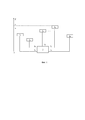
Фиг. 1. Схема антенной решетки со ступенчатой апертурой.FIG. 1. Scheme of the antenna array with a stepped aperture.
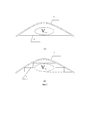
Фиг. 2. Эскизы расположения антенн плоской и ступенчатой компоновки в антенном обтекателе.FIG. 2. Sketches of the location of the antennas flat and stepped layout in the antenna fairing.
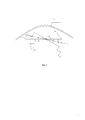
Фиг. 3. Сектора углов механического сканирования антенн плоской и ступенчатой компоновки.FIG. 3. Sector of the angles of mechanical scanning of antennas flat and step arrangement.
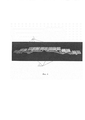
Фиг. 4. Образец антенной решетки со ступенчатой апертурой.FIG. 4. A sample antenna array with a stepped aperture.
Антенную решетку со ступенчатой апертурой (см. фиг. 1) формируют из N плоских коллинеарных подрешеток 1n, главный луч каждой из которых направлен перпендикулярно плоскости подрешетки, где n - номер подрешетки, n=1, … ,N, и СВЧ разветвителя 2, который содержит совокупность элементов распределения сигналов (отрезки волноводов, тройники волноводные Т-образных сочленения, делители и т.д.). С помощью СВЧ разветвителя 2 распределяют сигнал между подрешетками 1n, подсоединяя выход 2n СВЧ разветвителя 2 к подрешетке 1n, где n=1, …, N.An antenna array with a stepped aperture (see Fig. 1) is formed from N flat collinear sublattices 1 n , the main beam of each of which is perpendicular to the sublattice plane, where n is the number of the sublattice, n = 1, ..., N, and
Целесообразность использования антенных решеток со ступенчатой апертурой для их размещения в обтекателях сложной формы иллюстрируется на фиг. 2, фиг. 3.The feasibility of using arrays with a stepped aperture for their placement in complex-shaped radomes is illustrated in FIG. 2, FIG. 3
Из фиг. 2 видно, что при плоской апертуре (см. фиг. 2а) V- - объем между внутренней поверхностью антенного обтекателя 3 и плоской апертурой антенной решетки 4 использовать для размещения нельзя, поскольку любые элементы, помещаемые в этот объем, затеняют плоскую апертуру антенной решетки 4, а при ступенчатой апертуре антенной решетки 5 (см. фиг. 2б) часть этого объема объем V+ использовать можно. Например, в образце антенной решетки со ступенчатой апертурой, показанном на фиг. 4, в объеме V+ разместили элементы СВЧ разветвителя 2. Освободившийся объем, в частности, позволяет увеличить сектор углов механического сканирования антенны с величины α1 при плоской апертуре антенной решетки 4 до α2 при ступенчатой апертуре антенной решетки 5 (см. фиг. 3).From FIG. 2 shows that with a flat aperture (see FIG. 2a), the V - is the volume between the inner surface of the
Антенную решетку со ступенчатой апертурой формируют следующим образом (см. фиг. 1, фиг. 4).An antenna array with a stepped aperture is formed as follows (see Fig. 1, Fig. 4).
Формируют ступенчатую апертуру антенной решетки. Задают Ω(x,y) - плоскую область, которую разбивают на N областей Ωn(x,y), где n=1, …, N. Задают (см. фиг. 1) на оси 0Z, перпендикулярной плоскости области Ω(x,y), значения zn, где n=1, …, N. Область Ωn(х,у) смещают перпендикулярно оси 0Z и устанавливают по оси 0Z с координатой z=zn, где n=1, …, N. В области Ωn(x,y.z=zn) формируют апертуру плоской подрешетки под номером n, где n=1, …, N. Параметры областей Ω(x,y), Ωn(x,y) и значения zn выбирают с учетом геометрии антенного обтекателя и требований пользователя.Form a stepped aperture of the antenna array. Set Ω (x, y) is a flat area, which is divided into N areas Ω n (x, y), where n = 1, ..., N. Set (see Fig. 1) on the axis 0Z, perpendicular to the plane of the area Ω ( x, y), the values of z n , where n = 1, ..., N. The region Ω n (x, y) is shifted perpendicular to the axis 0Z and set along the axis 0Z with the coordinate z = z n , where n = 1, ..., N In the domain Ω n (x, yz = z n ), the aperture of the flat sublattice n is formed, where n = 1, ..., N. The parameters of the Ω (x, y) areas, Ω n (x, y) and the values of z n choose based on the geometry of the antenna fairing and user requirements.
Элементы СВЧ разветвителя 2 размещают во внутреннем объеме V+ (см. фиг. 2), образованным плоскими подрешетками 1n.The elements of the
Для обеспечения в антенной решетке со сформированной ступенчатой апертурой электрических характеристик, соответствующих электрическим характеристикам плоской антенной решетки с апертурой Ω(х,у), компенсируют разницу фаз между напряженностью поля в апертурах плоских подрешеток 1n, вызванную тем, что эти апертуры по оси 0Z лежат в разных параллельных плоскостях. Необходимую для компенсации величину сдвига фаз ϕn между напряженностью поля в апертуре плоской подрешетки под номером n и напряженностью поля в апертуре произвольно выбранной опорной плоской подрешетки под номером r вычисляют по формуле:In order to provide electrical characteristics corresponding to the electrical characteristics of the flat antenna array with the aperture Ω (x, y) in the antenna array with a stepped aperture, they compensate for the phase difference between the field strengths in the apertures of the flat sublattices 1 n , which lie along the 0Z axis in different parallel planes. The phase shift ϕ n required for compensation between the field strength in the aperture of the flat sublattice under number n and the field strength in the aperture of an arbitrarily selected supporting flat sublattice under number r is calculated by the formula:
где hn=zr-zn, zr - координата положения по оси OZ апертуры произвольно выбранной опорной плоской подрешетки по номером r, где 1<r<N, ![]()
![]()
![]()
![]()
С помощью разветвителя СВЧ сигнала 2 устанавливают величину сдвига фаз между напряженностью поля в апертуре плоской подрешетки под номером n и напряженностью поля в апертуре плоской подрешетки под номером r равной ϕn, где n=1, …, N.Using the
Патентуемый способ построения антенной решетки был успешно применен при проектировании антенной решетки Х-диапазона со ступенчатой апертурой, образец которой показан на фиг. 4. Экспериментально снятая диаграмма направленности данного образца антенной решетки со ступенчатой апертурой практически совпала с расчетной диаграммой направленности соответствующей плоской антенной решетки.The patented method of constructing an antenna array was successfully applied when designing an X-band antenna array with a stepped aperture, a sample of which is shown in FIG. 4. The experimentally captured radiation pattern of this sample of the antenna array with a stepped aperture almost coincided with the calculated radiation pattern of the corresponding flat antenna array.
Таким образом, реализуемость патентуемого способа построения антенной решетки с объемной апертурой подтверждена на практике.Thus, the feasibility of the patented method of constructing an antenna array with a volume aperture is confirmed in practice.
ЛитератураLiterature
1. M. Zhang, J. Hirokava, and M. Ando, "An E-band partially corporate feed uniform slot array with laminated quasi double-layer waveguide and virtual PMC terminations," IEEE Trans. Antennas Propag., vol. 59, no. 5, May 2011.1. M. Zhang, J. Hirokava, and M. Ando, "An E-bandwidth form factor for a double-layer waveguide and virtual PMC terminations," IEEE Trans. Antennas Propag., Vol. 59, no. 5, May 2011.
2. S. Fujii, Y. Tsunemitsu, G. Yoshida, N. Goto, M. Zhang, J. Hirokava, and M. Ando, "A wideband single-layer slotted waveguide array with an embedded partially corporate feed," presented at the ISAP2008, Taipei, Taiwan, Oct. 2008, TP-C27, paper No. 1645382.2. S. Fujii, Y. Tsunemitsu, G. Yoshida, N. Goto, M. Zhang, J. Hirokava, and M. Ando, "A wideband single-layer," presented at the ISAP2008, Taipei, Taiwan, Oct. 2008, TP-C27, paper No. 1645382.
3. M. Ando, Y. Tsunemitsu, M. Zhang, J. Hirokava, and S. Fujii, "Reduction of long line effects in single-layer slotted waveguide arrays with an embedded partially corporate feed," IEEE Trans. Antennas Propag., vol. 58, no. 7, Juiy 2010.3. M. Ando, Y. Tsunemitsu, M. Zhang, J. Hirokava, and S. Fujii, IEEE Trans. Antennas Propag., Vol. 58, no. 7, Juiy 2010.
4. Патент №2246156 Волноводно-щелевая антенная решетка / Иванов М.А., Хавкина Т.А., Котюргин Е.А., Ребров С.И., 10.02.20054. Patent No. 2226156 Wave-gap antenna array / Ivanov MA, Khavkina TA, Kotyurgin EA, Rebrov SI, February 10, 2005
Claims (1)
Priority Applications (1)
| Application Number | Priority Date | Filing Date | Title |
|---|---|---|---|
| RU2018105180A RU2691663C1 (en) | 2018-02-12 | 2018-02-12 | Method of constructing antenna array with stepped aperture |
Applications Claiming Priority (1)
| Application Number | Priority Date | Filing Date | Title |
|---|---|---|---|
| RU2018105180A RU2691663C1 (en) | 2018-02-12 | 2018-02-12 | Method of constructing antenna array with stepped aperture |
Publications (1)
| Publication Number | Publication Date |
|---|---|
| RU2691663C1 true RU2691663C1 (en) | 2019-06-17 |
Family
ID=66947734
Family Applications (1)
| Application Number | Title | Priority Date | Filing Date |
|---|---|---|---|
| RU2018105180A RU2691663C1 (en) | 2018-02-12 | 2018-02-12 | Method of constructing antenna array with stepped aperture |
Country Status (1)
| Country | Link |
|---|---|
| RU (1) | RU2691663C1 (en) |
Cited By (1)
| Publication number | Priority date | Publication date | Assignee | Title |
|---|---|---|---|---|
| RU2730051C1 (en) * | 2020-02-26 | 2020-08-14 | Акционерное общество "Особое конструкторское бюро Московского энергетического института" | Radiation pattern recovery method |
Citations (6)
| Publication number | Priority date | Publication date | Assignee | Title |
|---|---|---|---|---|
| US5453751A (en) * | 1991-04-24 | 1995-09-26 | Matsushita Electric Works, Ltd. | Wide-band, dual polarized planar antenna |
| RU2246156C1 (en) * | 2003-08-18 | 2005-02-10 | Федеральное государственное унитарное предприятие "Научно-производственное предприятие "Исток" | Slotted waveguide antenna array |
| RU2273923C2 (en) * | 2001-11-14 | 2006-04-10 | Квинтел Текнолоджи Лимитед | Antenna system |
| RU125397U1 (en) * | 2012-05-29 | 2013-02-27 | Федеральное государственное бюджетное образовательное учреждение высшего профессионального образования "Московский авиационный институт (национальный исследовательский университет)" (МАИ) | ACTIVE PHASED ANTENNA GRID WITH WIDE-ANGLE SCANNING |
| RU142208U1 (en) * | 2013-11-14 | 2014-06-20 | Федеральное государственное бюджетное образовательное учреждение высшего профессионального образования "Московский авиационный институт (национальный исследовательский университет)" (МАИ) | ACTIVE PHASED ANTENNA ARRAY WITH SPATIAL PLACEMENT OF ELEMENTS |
| US20170358866A1 (en) * | 2016-06-10 | 2017-12-14 | Intel IP Corporation | Array antenna arrangement |
-
2018
- 2018-02-12 RU RU2018105180A patent/RU2691663C1/en active IP Right Revival
Patent Citations (6)
| Publication number | Priority date | Publication date | Assignee | Title |
|---|---|---|---|---|
| US5453751A (en) * | 1991-04-24 | 1995-09-26 | Matsushita Electric Works, Ltd. | Wide-band, dual polarized planar antenna |
| RU2273923C2 (en) * | 2001-11-14 | 2006-04-10 | Квинтел Текнолоджи Лимитед | Antenna system |
| RU2246156C1 (en) * | 2003-08-18 | 2005-02-10 | Федеральное государственное унитарное предприятие "Научно-производственное предприятие "Исток" | Slotted waveguide antenna array |
| RU125397U1 (en) * | 2012-05-29 | 2013-02-27 | Федеральное государственное бюджетное образовательное учреждение высшего профессионального образования "Московский авиационный институт (национальный исследовательский университет)" (МАИ) | ACTIVE PHASED ANTENNA GRID WITH WIDE-ANGLE SCANNING |
| RU142208U1 (en) * | 2013-11-14 | 2014-06-20 | Федеральное государственное бюджетное образовательное учреждение высшего профессионального образования "Московский авиационный институт (национальный исследовательский университет)" (МАИ) | ACTIVE PHASED ANTENNA ARRAY WITH SPATIAL PLACEMENT OF ELEMENTS |
| US20170358866A1 (en) * | 2016-06-10 | 2017-12-14 | Intel IP Corporation | Array antenna arrangement |
Cited By (1)
| Publication number | Priority date | Publication date | Assignee | Title |
|---|---|---|---|---|
| RU2730051C1 (en) * | 2020-02-26 | 2020-08-14 | Акционерное общество "Особое конструкторское бюро Московского энергетического института" | Radiation pattern recovery method |
Similar Documents
| Publication | Publication Date | Title |
|---|---|---|
| Biswas et al. | A fern fractal leaf inspired wideband antipodal Vivaldi antenna for microwave imaging system | |
| CN113348594B (en) | Antenna and radar devices | |
| US11700056B2 (en) | Phased array antenna for use with low earth orbit satellite constellations | |
| US7595765B1 (en) | Embedded surface wave antenna with improved frequency bandwidth and radiation performance | |
| US20160013563A1 (en) | Wideband Twin Beam Antenna Array | |
| JP2013187752A (en) | Waveguide slot array antenna apparatus | |
| González-Ovejero et al. | Design, fabrication and testing of a modulated metasurface antenna at 300 GHz | |
| Genc et al. | Investigation of the characteristics of low-cost and lightweight horn array antennas with novel monolithic waveguide feeding networks | |
| You et al. | Numerical synthesis of dual-band reflectarray antenna for optimum near-field radiation | |
| RU2691663C1 (en) | Method of constructing antenna array with stepped aperture | |
| Schoebel et al. | Planar antenna technology for mm-wave automotive radar, sensing, and communications | |
| Akbar et al. | Use of subarrays in linear array for improving wide angular scanning performance | |
| JP2017112460A (en) | Antenna device | |
| Gonzalez et al. | Generalised design method of broadband array antennas using curved geometry | |
| Alexander et al. | Design of wide-band corrugated feed horn for reflector antenna in radar applications | |
| Pour et al. | Improved cross-polarization performance of a multi-phase-center parabolic reflector antenna | |
| Dong et al. | Extremely high-frequency beam steerable lens-fed antenna for vehicular sensor applications | |
| Zhai et al. | Randomly tiled rectangular sub-arrays for side lobe and grating lobe reduction in mm-Wave limited scanning phased array | |
| Colak et al. | SLL suppressed monopulse microstrip antenna design | |
| CN106170889A (en) | Antennas and Sector Antennas | |
| Turalchuk et al. | Analog beamforming based on Fourier Rotman lens for multibeam applications | |
| Khan et al. | Wideband Single‐Layer Reflectarray Antenna for Millimeter‐Wave 5G Communications | |
| Jung et al. | Ka-band shaped reflector hybrid antenna illuminated by microstrip-fed horn array | |
| Bertuch et al. | Wide-band radar front-end calibration for imaging SAR experiments with conformal antenna array | |
| Boriskin et al. | Synthesis of arbitrary-shaped lens antennas for beam-switching applications |
Legal Events
| Date | Code | Title | Description |
|---|---|---|---|
| MM4A | The patent is invalid due to non-payment of fees |
Effective date: 20200213 |
|
| NF4A | Reinstatement of patent |
Effective date: 20210302 |