RU2690282C1 - Trampoline connection and outboard attachment system - Google Patents
Trampoline connection and outboard attachment system Download PDFInfo
- Publication number
- RU2690282C1 RU2690282C1 RU2018135799A RU2018135799A RU2690282C1 RU 2690282 C1 RU2690282 C1 RU 2690282C1 RU 2018135799 A RU2018135799 A RU 2018135799A RU 2018135799 A RU2018135799 A RU 2018135799A RU 2690282 C1 RU2690282 C1 RU 2690282C1
- Authority
- RU
- Russia
- Prior art keywords
- tubular element
- trampoline
- support plate
- shock absorber
- springs
- Prior art date
Links
- 238000013016 damping Methods 0.000 claims abstract description 6
- 230000035939 shock Effects 0.000 claims description 27
- 239000006096 absorbing agent Substances 0.000 claims description 23
- 239000004033 plastic Substances 0.000 claims description 5
- 229920003023 plastic Polymers 0.000 claims description 5
- 230000000694 effects Effects 0.000 abstract description 2
- 239000000126 substance Substances 0.000 abstract 1
- 229910000831 Steel Inorganic materials 0.000 description 12
- 239000010959 steel Substances 0.000 description 12
- 208000027418 Wounds and injury Diseases 0.000 description 4
- 230000006378 damage Effects 0.000 description 4
- 208000014674 injury Diseases 0.000 description 4
- 239000004744 fabric Substances 0.000 description 3
- 239000006260 foam Substances 0.000 description 3
- 238000009434 installation Methods 0.000 description 3
- 238000005452 bending Methods 0.000 description 2
- 238000012986 modification Methods 0.000 description 2
- 230000004048 modification Effects 0.000 description 2
- 229920006362 Teflon® Polymers 0.000 description 1
- 238000010521 absorption reaction Methods 0.000 description 1
- 238000010276 construction Methods 0.000 description 1
- 238000005516 engineering process Methods 0.000 description 1
- 230000009191 jumping Effects 0.000 description 1
- 238000004519 manufacturing process Methods 0.000 description 1
- 239000000463 material Substances 0.000 description 1
- 230000002085 persistent effect Effects 0.000 description 1
- -1 polytetrafluoroethylene Polymers 0.000 description 1
- 229920001343 polytetrafluoroethylene Polymers 0.000 description 1
- 239000004810 polytetrafluoroethylene Substances 0.000 description 1
- 239000000725 suspension Substances 0.000 description 1
- 230000002459 sustained effect Effects 0.000 description 1
- 125000000391 vinyl group Chemical group [H]C([*])=C([H])[H] 0.000 description 1
- 229920002554 vinyl polymer Polymers 0.000 description 1
- 230000003313 weakening effect Effects 0.000 description 1
Images
Classifications
-
- A—HUMAN NECESSITIES
- A63—SPORTS; GAMES; AMUSEMENTS
- A63B—APPARATUS FOR PHYSICAL TRAINING, GYMNASTICS, SWIMMING, CLIMBING, OR FENCING; BALL GAMES; TRAINING EQUIPMENT
- A63B5/00—Apparatus for jumping
- A63B5/11—Trampolines
-
- A—HUMAN NECESSITIES
- A63—SPORTS; GAMES; AMUSEMENTS
- A63B—APPARATUS FOR PHYSICAL TRAINING, GYMNASTICS, SWIMMING, CLIMBING, OR FENCING; BALL GAMES; TRAINING EQUIPMENT
- A63B21/00—Exercising apparatus for developing or strengthening the muscles or joints of the body by working against a counterforce, with or without measuring devices
- A63B21/008—Exercising apparatus for developing or strengthening the muscles or joints of the body by working against a counterforce, with or without measuring devices using hydraulic or pneumatic force-resisters
- A63B21/0085—Exercising apparatus for developing or strengthening the muscles or joints of the body by working against a counterforce, with or without measuring devices using hydraulic or pneumatic force-resisters using pneumatic force-resisters
- A63B21/0087—Exercising apparatus for developing or strengthening the muscles or joints of the body by working against a counterforce, with or without measuring devices using hydraulic or pneumatic force-resisters using pneumatic force-resisters of the piston-cylinder type
-
- A—HUMAN NECESSITIES
- A63—SPORTS; GAMES; AMUSEMENTS
- A63B—APPARATUS FOR PHYSICAL TRAINING, GYMNASTICS, SWIMMING, CLIMBING, OR FENCING; BALL GAMES; TRAINING EQUIPMENT
- A63B21/00—Exercising apparatus for developing or strengthening the muscles or joints of the body by working against a counterforce, with or without measuring devices
- A63B21/02—Exercising apparatus for developing or strengthening the muscles or joints of the body by working against a counterforce, with or without measuring devices using resilient force-resisters
- A63B21/023—Wound springs
-
- A—HUMAN NECESSITIES
- A63—SPORTS; GAMES; AMUSEMENTS
- A63B—APPARATUS FOR PHYSICAL TRAINING, GYMNASTICS, SWIMMING, CLIMBING, OR FENCING; BALL GAMES; TRAINING EQUIPMENT
- A63B21/00—Exercising apparatus for developing or strengthening the muscles or joints of the body by working against a counterforce, with or without measuring devices
- A63B21/02—Exercising apparatus for developing or strengthening the muscles or joints of the body by working against a counterforce, with or without measuring devices using resilient force-resisters
- A63B21/04—Exercising apparatus for developing or strengthening the muscles or joints of the body by working against a counterforce, with or without measuring devices using resilient force-resisters attached to static foundation, e.g. a user
- A63B21/0407—Anchored at two end points, e.g. installed within an apparatus
- A63B21/0428—Anchored at two end points, e.g. installed within an apparatus the ends moving relatively by linear reciprocation
-
- A—HUMAN NECESSITIES
- A63—SPORTS; GAMES; AMUSEMENTS
- A63B—APPARATUS FOR PHYSICAL TRAINING, GYMNASTICS, SWIMMING, CLIMBING, OR FENCING; BALL GAMES; TRAINING EQUIPMENT
- A63B71/00—Games or sports accessories not covered in groups A63B1/00 - A63B69/00
- A63B71/0054—Features for injury prevention on an apparatus, e.g. shock absorbers
- A63B2071/0063—Shock absorbers
Abstract
Description
Область техникиTechnical field
Изобретение, в целом, относится к батутам и, в частности, к системе соединения и подвесного крепления батута с поворотной балкой и амортизирующим узлом, встроенным в вертикальную стойку.The invention generally relates to trampolines and, in particular, to a system for connecting and hanging a trampoline with a turntable and a shock-absorbing unit built into a vertical stand.
Уровень техникиThe level of technology
В последние семь лет в Соединенных Штатах быстрыми темпами увеличивается выпуск батут-парков, которые с недавнего времени представлены на международных рынках. Одной из самых больших проблем в этой области являются травмы пользователей, когда они приземляются на маты батутов. В обычной конструкции каркас батута, состоящий из стальных штанг и/или стальных тросов, расположен под матами батута, и пружины соединяют полотно батута (поверхность для совершения прыжков) с балками батута (стальные штанги или стальные тросы). К верхней части балки обычно крепится толстая подушка из винилового пенопласта, закрывающая расположенные снизу каркас и пружины. Эта подушка из пенопласта является единственной мягкой поверхностью для защиты пользователя от травмы, если он приземляется на балки батута.In the past seven years, the release of trampoline parks in the United States, which have recently been presented on international markets, has increased at a rapid pace. One of the biggest problems in this area are user injuries when they land on trampoline mats. In a conventional design, the trampoline frame, consisting of steel rods and / or steel cables, is located under the trampoline mats, and the springs connect the trampoline canvas (surface for jumping) to the trampoline beams (steel rods or steel cables). A thick cushion of vinyl foam is usually attached to the top of the beam, covering the frame and springs located below. This foam pillow is the only soft surface to protect the user from injury if he lands on the trampoline beams.
В батут-парке, в котором для изготовления каркаса батута вместо стальных штанг используют стальные тросы, удары пользователя в случае приземления на перила до некоторой степени ослабляются за счет ограниченного изгиба стальных тросов; однако величина изгиба, обеспечиваемая стальными тросами, ограничена и сама создает проблемы. В частности, удар пользователя при контакте со стальными тросами главным образом не поглощается (имеет место лишь незначительное поглощение энергии), а передается через тросы взаимосвязанным батутам, создавая волновой эффект среди всех стальных тросов по всей площадке, снижая их эффективность при поглощении энергии после удара. Батут-парки со стальными штангами, поддерживающими батуты, вообще не обеспечивают поглощение энергии после удара, тем самым создавая риск серьезной травмы.In the trampoline park, in which steel cables are used instead of steel rods to manufacture a trampoline frame, the user's strikes in case of landing on the railing are weakened to some extent due to the limited bending of the steel cables; however, the amount of bending provided by steel cables is limited and creates problems itself. In particular, the user's impact on contact with steel cables is mostly not absorbed (only slight energy absorption takes place), but is transmitted through cables to interconnected trampolines, creating a ripple effect among all steel cables throughout the site, reducing their effectiveness in absorbing energy after impact. Trampoline parks with steel bars supporting trampolines do not absorb energy at all after an impact, thereby creating the risk of serious injury.
Изобретение решает проблему травм, получаемых пользователями в результате приземления на подушки/балки батута, благодаря установке амортизирующего узла в каркас батута. Эта система позволяет балкам поворачиваться при ударе, тем самым ослабляя силу удара, действующую на клиента. Известны некоторые патентные документы, относящиеся к батуту и его конструкции, но ни одно из описанных устройств не обеспечивает такую безопасность, как заявленное изобретение.The invention solves the problem of injuries sustained by users as a result of landing on the cushions / beams of the trampoline, due to the installation of a shock-absorbing unit in the trampoline frame. This system allows the beams to rotate upon impact, thereby weakening the impact force acting on the client. There are some patent documents related to the trampoline and its design, but none of the described devices provide such security as the claimed invention.
В патентном документе US 3,677,368 описан батут с рамой, изготовленной из трубчатого материала и поддерживаемой стойками, которые препятствуют перемещению рамы вниз в ответ на направленную вниз нагрузку на раму. Изобретение также включает в себя «поддерживаемое с возможностью деформации» смягчающее средство на раме для амортизации удара пользователя о раму.In the patent document US 3,677,368 described trampoline with a frame made of tubular material and supported by racks that prevent the frame from moving downwards in response to the downward load on the frame. The invention also includes a "supported with the possibility of deformation" softening means on the frame to absorb the impact of the user on the frame.
В патентном документе US 5,336,135 описано устройство для развлечения, состоящее из группы батутов, расположенных вертикально и смещенных так, чтобы пользователь мог последовательно перепрыгивать с самых верхних батутов на нижние батуты. В одном из вариантов выполнения батут имеет жесткую опорную конструкцию за исключением участка, который может отклоняться, когда к батуту прикладывается излишнее усилие. Последний вариант выполнения включает в себя криволинейную «изогнутую штангу», оканчивающуюся стальной пружиной для частичного поглощения силы удара.In the patent document US 5,336,135 describes a device for entertainment, consisting of a group of trampolines, arranged vertically and offset so that the user can consistently jump from the uppermost trampolines to the lower trampolines. In one embodiment, the trampoline has a rigid support structure, with the exception of a section that may deviate when excessive force is applied to the trampoline. The latter embodiment includes a curvilinear “curved bar”, terminated by a steel spring to partially absorb the impact force.
В патентном документе US 6,598,365 описано устройство, поглощающее ударную нагрузку и энергию, для полов, стен и других плоских поверхностей. Изобретение, по существу, включает в себя установку цилиндрических пружин по всему участку, подлежащему защите. Имеющие раструб вставки прикреплены к пружинам и вставлены в принимающий элемент, который прикреплен к плоской поверхности.In the patent document US 6,598,365 described a device that absorbs shock load and energy for floors, walls and other flat surfaces. The invention essentially includes the installation of coil springs throughout the area to be protected. The bell-shaped inserts are attached to the springs and inserted into the receiving element, which is attached to a flat surface.
В патентном документе US 6,662, 538 описан так называемый «безопасный» батут, состоящий, в целом, из круглого внутреннего полотна с множеством внутренних плоских пружин, распределенных по его периметру, и, в целом, круглого наружного полотна с множеством наружных плоских пружин, распределенных по его периметру. Соединительные канаты крепят внутренние плоские пружины к внутреннему канату и наружные плоские пружины к наружному полотну.In the patent document US 6,662, 538 described the so-called "safe" trampoline, consisting, in General, from a round inner canvas with many internal flat springs, distributed around its perimeter, and, in General, round outer fabric with many external flat springs, distributed along its perimeter. The connecting ropes attach the inner flat springs to the inner rope and the outer flat springs to the outer web.
В патентном документе US 6,733,420 описано устройство для тренировок, состоящее из рамы, образованной угловыми элементами, соединенными у их смежных углов, и включающее в себя заплечики и косынки и полотно из ткани, расположенное внутри рамы и соединенное с ней цилиндрическими пружинами. Плунжер, расположенный в узле стойки, обеспечивает дополнительное перемещение во время использования устройства.In patent document US 6,733,420, a training device is described, consisting of a frame formed by angular elements connected at their adjacent corners, and including shoulders and kerchiefs and a cloth made of fabric, located inside the frame and connected to it by coil springs. A plunger located in a rack assembly provides additional movement during use of the device.
В патентном документе US 8,668,190 описана поглощающая удары конструкция с вертикальной полой колонной, которая телескопически охватывает стойку. Между опорной пластиной сверху вертикальной полой колонны и верхней пластиной, которая соединена с верхним концом стойки, расположена цилиндрическая пружина. Стойка убирается внутрь полой колонны, и пружина сжимается, когда направленное вниз усилие прикладывается к верхней пластине.In the patent document US 8,668,190 described absorbing shock construction with a vertical hollow column, which telescopically covers the rack. Between the base plate on top of the vertical hollow column and the top plate, which is connected to the upper end of the rack, is a cylindrical spring. The rack retracts inside the hollow column, and the spring is compressed when a downward force is applied to the top plate.
В патентном документе US 2006/0116242 описан батут с регулируемым натяжением пружин, причем пружины или другие упругие соединители поддерживают полотно с рамой батута и соединены друг с другом с возможностью регулирования. Натяжение между пружинами можно регулировать для обеспечения большего или меньшего натяжения между соседними пружинами (или группами соседних пружин).In the patent document US 2006/0116242, a trampoline with adjustable tension of springs is described, with springs or other elastic connectors supporting the canvas with the trampoline frame and being connected to each other with the possibility of regulation. The tension between the springs can be adjusted to provide more or less tension between adjacent springs (or groups of adjacent springs).
Раскрытие изобретенияDISCLOSURE OF INVENTION
Согласно изобретению система соединения и подвесного крепления батута содержит: продолговатую балку, шарнирно прикрепленную к телескопической вертикальной стойке, которая включает в себя первый трубчатый элемент, второй трубчатый элемент и опорную пластину, при этом первый трубчатый элемент является полым и прикреплен к опорной пластине, отходя от нее верх, а второй трубчатый элемент телескопически установлен внутри первого трубчатого элемента; верхний конец второго трубчатого элемента образует по меньшей мере один канал, внутрь которого вставлен первый конец балки, при этом первый конец балки содержит ось и выполнен с возможностью поворота вокруг этой оси относительно верхнего конца второго трубчатого элемента; первый и второй трубчатые элементы содержат амортизирующий узел, включающий в себя нижнюю цилиндрическую стойку нижним концом прикрепленную к опорной пластине, которая выполнена с возможностью установки внутри первого трубчатого элемента, при этом амортизатор нижним концом прикреплен к верхнему концу нижней цилиндрической стойки, а верхним концом прикреплен к верхнему концу второго трубчатого элемента.According to the invention, the system for connecting and hanging the trampoline comprises: an elongated beam hinged to a vertical telescopic stand that includes a first tubular element, a second tubular element, and a support plate, the first tubular element being hollow and attached to the support plate, extending from its top, and the second tubular element is telescopically mounted inside the first tubular element; the upper end of the second tubular element forms at least one channel into which the first end of the beam is inserted, while the first end of the beam contains an axis and is rotatable about this axis relative to the upper end of the second tubular element; the first and second tubular elements comprise a damping unit including a lower cylindrical rack with a lower end attached to a support plate, which is adapted to be mounted inside the first tubular element, while the shock absorber with a lower end attached to the upper end of the lower cylindrical rack, and the upper end attached to the upper end of the second tubular element.
В предпочтительном варианте выполнения второй трубчатый элемент содержит четыре наружные поверхности и четыре пластиковые накладки, каждая из которых зафиксирована на наружной поверхности второго трубчатого элемента. Предпочтительно, балка содержит средства для крепления пружин батута. Средства для крепления пружин батута предпочтительно представляют собой один или несколько зигзагообразных элементов.In a preferred embodiment, the second tubular element contains four outer surfaces and four plastic lining, each of which is fixed on the outer surface of the second tubular element. Preferably, the beam comprises means for securing the trampoline springs. The means for fixing the springs of the trampoline are preferably one or more zigzag elements.
В предпочтительном варианте выполнения первый конец балки имеет цилиндрический канал, внутри которого установлена цилиндрическая втулка, при этом через центральное отверстие цилиндрической втулки проходит ось. Предпочтительно, амортизирующий узел дополнительно содержит цилиндрическую пружину, расположенную вокруг нижней цилиндрической стойки между опорной и верхней пластинами, причем верхняя пластина расположена на верхнем конце нижней цилиндрической стойки. Амортизатор предпочтительно представляет собой газовую пружину.In a preferred embodiment, the first end of the beam has a cylindrical channel within which there is a cylindrical sleeve, and an axis passes through the central hole of the cylindrical sleeve. Preferably, the cushion assembly further comprises a coil spring located around the lower coil post between the support plate and the top plate, with the top plate located at the top end of the coil post bottom. The shock absorber is preferably a gas spring.
В предпочтительном варианте выполнения ось проходит через паз, образованный в каждой из двух пластин с каждой стороны первого конца балки, при этом паз выполнен с возможностью обеспечения перемещения в нем оси в боковом направлении во время поворота балки.In a preferred embodiment, the axis passes through a groove formed in each of the two plates on each side of the first end of the beam, wherein the groove is adapted to move the axis therein in the lateral direction during the rotation of the beam.
Краткое описание чертежейBrief Description of the Drawings
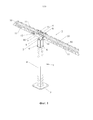
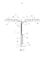
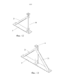
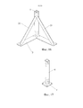
На фиг. 1 показана система соединения и подвесного крепления батута согласно изобретению, вид в перспективе;FIG. 1 shows a system for connecting and hanging a trampoline according to the invention, in perspective view;
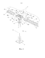
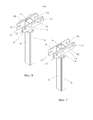
на фиг. 2 – место крепления балки согласно изобретению в разобранном состоянии;in fig. 2 - the place of fastening of the beam according to the invention in a disassembled state;
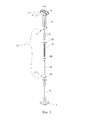
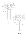
на фиг. 3 – амортизирующий узел согласно изобретению в разобранном состоянии;in fig. 3 shows a shock absorbing assembly according to the invention in a disassembled state;
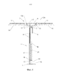
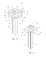
на фиг. 4 – система соединения подвесного крепления батута согласно изобретению с амортизатором в несжатом положении, вид в разрезе;in fig. 4 shows a system for connecting the suspension mounting of a trampoline according to the invention with a shock absorber in an uncompressed position, a sectional view;
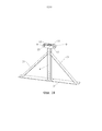
на фиг. 5 – система соединения и подвесного крепления батута согласно изобретению с амортизатором в сжатом положении, вид в разрезе;in fig. 5 shows a system for connecting and hanging the trampoline according to the invention with a shock absorber in a compressed position, a sectional view;
на фиг. 6 – верхняя часть вертикальной стойки согласно первому варианту осуществления изобретения, вид в перспективе;in fig. 6 is the upper part of the upright stand according to the first embodiment of the invention, a perspective view;
на фиг. 7 – верхняя часть вертикальной стойки согласно первому варианту осуществления изобретения, вид в перспективе;in fig. 7 is the upper part of the vertical stand according to the first embodiment of the invention, a perspective view;
на фиг. 8 – верхняя часть вертикальной стойки согласно второму варианту осуществления изобретения, вид в перспективе;in fig. 8 is the upper part of the vertical stand according to the second embodiment of the invention, a perspective view;
на фиг. 9 – верхняя часть вертикальной стойки согласно третьему варианту осуществления изобретения, вид в перспективе;in fig. 9 is the upper part of the vertical stand according to the third embodiment of the invention, a perspective view;
на фиг. 10 – верхняя часть вертикальной стойки согласно четвертому варианту осуществления изобретения, вид в перспективе;in fig. 10 is the upper part of the vertical stand according to the fourth embodiment of the invention, a perspective view;
на фиг. 11 – верхняя часть вертикальной стойки согласно пятому варианту осуществления изобретения, вид в перспективе;in fig. 11 is the upper part of the vertical stand according to the fifth embodiment of the invention, a perspective view;
на фиг. 12 – нижняя часть вертикальной стойки согласно первому варианту осуществлению изобретения, вид в перспективе;in fig. 12 is the lower part of the upright stand according to the first embodiment of the invention, is a perspective view;
на фиг. 13 – нижняя часть вертикальной стойки согласно второму варианту осуществления изобретения, вид в перспективе;in fig. 13 is the lower part of the upright stand according to the second embodiment of the invention, in perspective view;
на фиг. 14 – нижняя часть вертикальной стойки согласно третьему варианту осуществления изобретения, вид в перспективе;in fig. 14 is the lower part of the upright stand according to the third embodiment of the invention, in perspective view;
на фиг. 15 – нижняя часть вертикальной стойки согласно четвертому варианту осуществления изобретения, вид в перспективе;in fig. 15 is a bottom view of the upright stand according to a fourth embodiment of the invention, is a perspective view;
на фиг. 16 – нижняя часть вертикальной стойки согласно пятому варианту осуществления изобретения, вид в перспективе;in fig. 16 is a lower part of the upright stand according to the fifth embodiment of the invention, in perspective view;
на фиг. 17 – нижняя часть вертикальной стойки согласно шестому варианту осуществления изобретения, вид в перспективе;in fig. 17 is the lower part of the upright stand according to the sixth embodiment of the invention, a perspective view;
на фиг. 18 – неподвижная вертикальная стойка без амортизирующего узла, вид в перспективе;in fig. 18 is a fixed vertical stand without a shock-absorbing unit, perspective view;
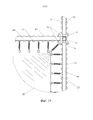
на фиг. 19 – полотно батута, закрепленное системой соединения и подвесного крепления батута согласно изобретению, вид сверху.in fig. 19 is a trampoline web attached by a system for connecting and hanging a trampoline according to the invention, top view.
Ссылочные позицииReference Items
1 – вертикальная стойка1 - vertical stand
2 – узел горизонтально расположенных балок 2 - a node of horizontal beams
3 – опорная пластина3 - support plate
4 – первый трубчатый элемент4 - the first tubular element
5 – второй трубчатый элемент5 - the second tubular element
6 – пластиковая накладка6 - plastic lining
7 – болт7 - bolt
8 – амортизатор8 - shock absorber
9 – приемный кронштейн9 - receiving bracket
9a – опорная пластина9a - support plate
9b – приемная пластина9b - receiving plate
9c – дугообразный элемент9c - arcuate element
10 – балка10 - beam
10a – цилиндрический канал10a - cylindrical channel
11 – зигзагообразный элемент11 - zigzag element
12 – болт12 - bolt
12a – отверстие (для болта 12)12a - hole (for bolt 12)
13 – паз (в приемном кронштейне)13 - groove (in the receiving bracket)
14 – амортизирующий узел 14 - shock absorbing unit
15 – нижняя стойка15 - lower rack
16 – опорная пластина16 - support plate
17 – штифт17 - pin
18 – упорное кольцо пружины18 - a persistent ring of a spring
19 – цилиндрическая пружина19 - cylindrical spring
20 – верхняя пластина20 - top plate
21 – опорный кронштейн21 - support bracket
22 – полотно батута22 - trampoline canvas
23 – пружины батута23 - trampoline springs
24 – втулка24 - sleeve
Осуществление изобретенияThe implementation of the invention
На фиг. 1 показана система соединения и подвесного крепления батута согласно изобретению. На этой фигуре изображена вертикальная стойка 1 и узел 2 горизонтально расположенных балок. Вертикальная стойка 1 содержит опорную пластину 3, первый трубчатый элемент 4 (полый), прикрепленный к опорной пластине 3 и отходящий от нее вверх, и второй трубчатый элемент 5 (полый), который телескопически вставлен внутрь первого трубчатого элемента 4. Наружная ширина второго трубчатого элемента 5 меньше внутренней ширины первого трубчатого элемента 4, и второй трубчатый элемент 5 предпочтительно содержит четыре плоских пластиковых накладки 6 (предпочтительно из политетрафторэтилена или TEFLON®), каждая из которых прикреплена к одной из четырех наружных поверхностей второго трубчатого элемента 5. Первый и второй трубчатые элементы 4, 5 являются продолговатыми. Пластиковые накладки 6 предпочтительно проходят от верхней части второго трубчатого элемента 5 непосредственно от болта 7, который крепит амортизатор 8 (не показан) ко второму трубчатому элементу 5 по всей его длине до нижней части второго трубчатого элемента 5 (фиг. 3). Следует отметить, что верхний конец первого трубчатого элемента 4 открыт, (так что второй трубчатый элемент 5 может перемещаться со скольжением внутри него), и нижний конец первого трубчатого элемента 4 закрыт (поскольку он приварен к опорной пластине 3. Верхний и нижний концы второго трубчатого элемента 5 предпочтительно открыты.FIG. 1 shows a system for connecting and hanging the trampoline according to the invention. This figure shows a
К верхнему концу второго трубчатого элемента 5 приварены два продолговатых приемных кронштейна 9. Каждый приемный кронштейн 9 ориентирован горизонтально и перпендикулярно к центральной оси первого 4 и второго 5 трубчатых элементов. В этом варианте выполнения каждый приемный кронштейн 9 приварен к наружной стороне второго трубчатого элемента 5, и приемные кронштейны 9 расположены на противоположных поверхностях второго трубчатого элемента 5. Высота приемного кронштейна 9 предпочтительно такая же, как и высота балки 10, а ширина приемного кронштейна 9 предпочтительно равна, по меньшей мере, трем значениям ширины второго трубчатого элемента 5. Приемный кронштейн 9 предпочтительно отцентрирован с верхним концом второго трубчатого элемента 5.Two elongated receiving
В предпочтительном варианте выполнения приемный кронштейн 9 содержит зигзагообразный элемент 11, который приварен снаружи этого приемного кронштейна 9 и служит в качестве места крепления пружин батута (не показаны). Балка 10 шарнирно прикреплена к каждому концу приемного кронштейна 9. Как показано на фиг. 1, один конец балки 10 установлен между двумя противоположными концами двух приемных кронштейнов 9 и прикреплен к ним болтом 12, который проходит через оба приемных кронштейна 9 и расположенный между ними конец балки 10. В предпочтительном варианте выполнения зигзагообразный элемент 11 приварен к двум обращенным в горизонтальном направлении наружным поверхностям каждого из приемных кронштейнов 9; эти зигзагообразные элементы 11 служат в качестве мест крепления пружин батута (не показаны). Следует отметить, что высота балки 10 предпочтительно примерно такая же, как и высота приемного кронштейна 9, а ширина балки 10 примерно равна расстоянию между внутренними поверхностями противоположных приемных кронштейнов 9. Также следует отметить, что верхний конец второго трубчатого элемента 5 предпочтительно оканчивается немного ниже верхнего края приемного кронштейна 9.In a preferred embodiment, the receiving
На фиг. 2 показано место крепления балки согласно изобретению в разобранном состоянии. На этой фигуре болты 12, проходят через приемные кронштейны 9 и балки 10, проходят через горизонтальные пазы 13, расположенные на каждом конце приемных кронштейнов 9. Эти пазы 13 предпочтительно продолговатые, т.е. ширина паза больше высоты паза по причинам, описанным ниже со ссылкой на фиг. 4 и 5. В предпочтительном варианте выполнения внутри цилиндрического канала 10a на конце балки 10 установлена цилиндрическая втулка 24, которая вставлена в канал между двумя приемными кронштейнами 9. Каждый болт 12 проходит через пазы 13 в приемных кронштейнах 9, а также через центральное отверстие 12a во втулке 24. Следует отметить, что болт 12 действует в качестве оси, вокруг которой поворачивается конец балки 10.FIG. 2 shows the fastening point of the beam according to the invention in a disassembled state. In this figure, the
На фиг. 3 показан амортизирующий узел 14 согласно изобретению в разобранном состоянии. Как показано на этой фигуре, амортизирующий узел 14 содержит нижнюю цилиндрическую стойку 15, прикрепленную к одному концу опорной пластины 16, выполненной с возможностью установки внутри первого трубчатого элемента 4. Штифт 17 крепит нижний конец нижней цилиндрической стойки 15 к упорному кольцу 18 пружины, которое проходит вокруг нижней цилиндрической стойки 15 и расположено сверху опорной пластины 16. Используемая по выбору цилиндрическая пружина 19 расположена вокруг нижней цилиндрической стойки 15 между опорной пластиной 16 и верхней пластиной 20; верхняя пластина 20 упирается в нижнюю поверхность второго трубчатого элемента 5. Нижний конец амортизатора 8, предпочтительно в виде газовой пружины, ввинчен в верхний конец нижней цилиндрической стойки 15. На фиг. 1 верхняя часть газовой пружины 8 прикреплена к верхнему концу второго трубчатого элемента 5 (непосредственно под приемным кронштейном 9) болтом 7. Амортизатор 8 расположен внутри второго трубчатого элемента 5 между верхней пластиной 20 и верхним концом второго трубчатого элемента 5. В варианте выполнения без цилиндрической пружины 19 использование верхней пластины 20 или упорного кольца 18 пружины не является обязательным.FIG. 3 shows the damping
На фиг. 4 показана в разрезе система соединения и подвесного крепления батута согласно изобретению с амортизатором в несжатом положении, и на фиг. 5 показана в разрезе система соединения и подвесного крепления батута согласно изобретению с амортизатором в сжатом положении. Как показано на фиг. 4, когда на балку 10 не помещена никакая масса, амортизатор 8 полностью выдвинут, и балка 10 остается горизонтальной (т.е. перпендикулярной первому и второму трубчатым элементам 4, 5); однако, как показано на фиг. 5, когда к балке 10 прикладывают направленную вниз силу, она поворачивается относительно вертикальной стойки 1, так что эта балка 10 перемещается (или поворачивается) вниз возле приемного кронштейна 9, когда амортизатор втягивается.FIG. 4 shows a sectional view of a system for connecting and hanging the trampoline according to the invention with a shock absorber in an uncompressed position, and FIG. 5 shows a sectional view of a system for connecting and hanging a trampoline according to the invention with a shock absorber in a compressed position. As shown in FIG. 4, when no mass is placed on the
Следует отметить, что другой конец балки 10 (не показан) может быть соединен с другой вертикальной стойкой с амортизатором или он может быть соединен с вертикальной стойкой без амортизатора (фиг. 18). Если оба конца перила соединены с вертикальной стойкой, содержащей амортизатор, вся балка будет до некоторой степени перемещаться вниз, и конец балки, который соединен (через приемный кронштейн) с верхом вертикальной стойки, будет поворачиваться (относительно приемного кронштейна) до некоторой степени, как показано на фиг. 4. Если, с другой стороны, другой конец балки соединен с вертикальной стойкой без амортизатора, конец балки, который соединен (через приемный кронштейн) с верхней частью вертикальной стойки, будет перемещаться вниз (или поворачиваться относительно приемного кронштейна) в большей степени, чем показано на фиг. 4; другими словами, балка, по-видимому, будет расположена под большим углом относительно второго трубчатого элемента, чем показано на фиг. 4, поскольку конец балки, который расположен над амортизатором, будет перемещаться вниз на расстояние, равное степени втягивания амортизатора.It should be noted that the other end of the beam 10 (not shown) can be connected to another vertical stand with a shock absorber, or it can be connected to a vertical stand without a shock absorber (Fig. 18). If both ends of the railing are connected to a vertical stand containing a shock absorber, the entire beam will move down to some extent, and the end of the beam that is connected (via the receiving bracket) to the top of the vertical stand will rotate (relative to the receiving bracket) to some extent, as shown in fig. 4. If, on the other hand, the other end of the beam is connected to a vertical stand without a shock absorber, the end of the beam that is connected (via the receiving bracket) to the top of the vertical stand will move down (or rotate relative to the receiving bracket) to a greater degree than shown. in fig. four; in other words, the beam is likely to be located at a greater angle relative to the second tubular element than shown in FIG. 4, since the end of the beam, which is located above the shock absorber, will move down a distance equal to the extent that the shock absorber retracts.
Следует также отметить относительные положения болтов 12 (не показаны) в пазах 13 приемных кронштейнов 9 на фиг. 4 и 5. В положении, показанном на фиг. 4 (на балку не воздействует никакая масса), болты установлены в том конце паза 13, который наиболее близко расположен к вертикальной стойке 1. В положении, показанном на фиг. 5 (на балку воздействует масса), болты 12 перемещены наружу внутри пазов 13. В предпочтительном варианте выполнения пазы 13 выполнены так, чтобы болты 12 могли перемещаться в боковом направлении внутри пазов 13, когда балка поворачивается. Когда второй трубчатый элемент 5 движется вниз под нагрузкой, он толкает верхнюю пластину 20 вниз, тем самым сжимая цилиндрическую пружину 19 между упорным кольцом 18 пружины и верхней пластиной 20. При подъеме массы цилиндрическая пружина 19 толкает верхнюю пластину 20 и второй трубчатый элемент 5 вверх, тем самым способствуя амортизатору/газовой пружине 8 в подъеме всего узла 2 вверх. На фиг. 4 и 5 болты 12 не показаны для ясности, но обозначены отверстия 12a во втулке 24 (на конце балки 10), через которые проходят болты.It should also be noted the relative positions of the bolts 12 (not shown) in the
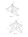
На фиг. 6 – 10 показаны другие варианты выполнения приемных кронштейнов 9. На фиг. 6 показан приемный кронштейн такой же формы, как и на предыдущих фигурах. На фиг. 7 показан приемный кронштейн такой же формы, как и на фиг 6, за исключением того, что на одном из приемных кронштейнов зигзагообразные элементы 11 отсутствуют. На фиг. 8 показаны приемные кронштейны такой формы, где один из приемных кронштейнов является таким же, как показано на фиг. 6, а другой приемный кронштейн состоит из опорной пластины 9a (сходной с приемным кронштейном 9, описанным со ссылкой на предыдущие фигуры) и двух более коротких приемных пластин 9b, которые параллельны друг другу и проходят наружу от опорной пластины 9a под углом девяносто (90) градусов. Каждая из двух приемных пластин 9b содержит паз 13, описанный выше, и опорная пластина 9a на каждом конце содержит паз 13. Две балки 10 (не показаны) вставлены между приемным кронштейном 9 и опорной пластиной 9a и закреплены болтами (не показаны), которые позволяют поворачивать балки относительно приемного кронштейна/опорной пластины, как описано выше. Одно балка 10 (не показано) вставлена в углубление между двумя приемными пластинами 9b и закреплена в нем болтом (не показан), который позволяет этой балке поворачиваться относительно приемных пластин 9b. Таким образом, форма вертикальной стойки, показанная на фиг. 8, позволяет устанавливать три балки, а не две. Вариант выполнения, показанный на фиг. 9, отличается от варианта выполнения, показанного на фиг. 8, тем, что на одном приемном кронштейне 9 зигзагообразные элементы отсутствуют. Дугообразные элементы 9c между приемными пластинами 9b и опорной пластиной 9a обеспечивают дополнительную опору конструкции.FIG. 6 to 10, other embodiments of the receiving
Вариант выполнения, показанный на фиг. 10, состоит из двух опорных пластин 9a и четырех приемных пластин 9b. Эта конкретная форма позволяет размещать четыре поворотных балки. Вариант выполнения, показанный на фиг. 11, состоит из трех коротких опорных пластин 9a и одной приемной пластины 9b; этот вариант выполнения может обеспечить размещение двух балок 10, ориентированных перпендикулярно друг другу.The embodiment shown in FIG. 10 consists of two supporting
На фиг. 12 – 17 показаны другие варианты выполнения нижней части вертикальной стойки. Первый трубчатый элемент 4 является таким же, как и во всех этих вариантах выполнения. Как показано, опорная пластина 3 может иметь любую из различных форм, показанных на этих фигурах (или любую другую форму); изобретение не ограничивается каким-либо конкретным размером или формой опорной пластины 3. Первый трубчатый элемент 4 также может поддерживаться одним или несколькими диагональными опорными кронштейнами 21. Опорные кронштейны 21 приварены на одном конце к первому трубчатому опорному элементу 4 и на другом конце к опорной пластине 3.FIG. 12-17 shows other embodiments of the lower part of the vertical rack. The first
На фиг. 18 показана неподвижная вертикальная стойка без амортизирующего узла. Как указано выше, в некоторых компоновках батут-парка предпочтительным является крепление одного конца балки к вертикальной стойке с амортизатором, показанным на фиг. 1, и другого конца балки к вертикальной стойке без амортизатора. В вертикальной стойке, показанной на этой фигуре, не предусмотрен второй трубчатый элемент (позиция 5 на фиг. 1); предусмотрен только первый трубчатый элемент 4, верхний конец которого приварен к внутренним поверхностям двух параллельных приемных кронштейнов 9. В этом варианте выполнения наружная ширина первого трубчатого элемента 4 является такой же, как наружная ширина второго трубчатого элемента 5, показанного в предыдущих вариантах выполнения, поскольку верхний конец трубчатого элемента должен иметь приблизительно такую же наружную ширину, как и балка, для установки внутри канала, образуемого приемными кронштейнами 9, опорными пластинами 9a и/или приемными пластинами 9c.FIG. 18 shows a fixed vertical stand without a damping assembly. As indicated above, in some trampoline park layouts, it is preferable to mount one end of the beam to a vertical stand with a shock absorber shown in FIG. 1, and the other end of the beam to the vertical stand without a shock absorber. In the upright rack shown in this figure, a second tubular member is not provided (
На фиг. 19 подробно показан вид сверху на полотно батута, закрепленного системой соединения и подвесного крепления батута согласно изобретению. Как показано на этой фигуре, в полностью собранном состоянии полотно 22 батута соединено с зигзагообразными элементами 11 и/или дугообразными элементами 9c посредством пружин 23. Вокруг полотна 22 батута расположена подушка из вспененного материала (не показана), соединенная с конструкцией балок.FIG. 19 shows in detail a top view of the trampoline web attached by the system for connecting and hanging the trampoline according to the invention. As shown in this figure, in the fully assembled state, the
Несмотря на то, что был показан и описан предпочтительный вариант выполнения, специалисту в этой области должно быть понятно, что могут быть выполнены многочисленные изменения и модификации без отклонения от сущности изобретения. Следовательно, приложенная формула изобретения включает в себя все варианты и модификации, соответствующие сущности и объему изобретения.Although a preferred embodiment has been shown and described, it should be clear to a person skilled in the art that numerous changes and modifications can be made without departing from the spirit of the invention. Therefore, the appended claims include all variations and modifications corresponding to the nature and scope of the invention.
Claims (10)
Applications Claiming Priority (3)
| Application Number | Priority Date | Filing Date | Title |
|---|---|---|---|
| US15/068,093 US9717940B1 (en) | 2016-03-11 | 2016-03-11 | Trampoline suspension mount and connection system |
| US15/068,093 | 2016-03-11 | ||
| PCT/US2016/022434 WO2017155555A1 (en) | 2016-03-11 | 2016-03-15 | Trampoline suspension mount and connection system |
Publications (1)
| Publication Number | Publication Date |
|---|---|
| RU2690282C1 true RU2690282C1 (en) | 2019-05-31 |
Family
ID=59382782
Family Applications (1)
| Application Number | Title | Priority Date | Filing Date |
|---|---|---|---|
| RU2018135799A RU2690282C1 (en) | 2016-03-11 | 2016-03-15 | Trampoline connection and outboard attachment system |
Country Status (16)
| Country | Link |
|---|---|
| US (1) | US9717940B1 (en) |
| EP (1) | EP3413983B1 (en) |
| JP (1) | JP6754453B2 (en) |
| KR (1) | KR102548281B1 (en) |
| CN (1) | CN108883324B (en) |
| AU (1) | AU2016396166B2 (en) |
| BR (1) | BR112018068329B1 (en) |
| CA (1) | CA3017456C (en) |
| CO (1) | CO2018010551A2 (en) |
| ES (1) | ES2784918T3 (en) |
| HK (1) | HK1257619A1 (en) |
| MX (1) | MX2018011030A (en) |
| PL (1) | PL3413983T3 (en) |
| PT (1) | PT3413983T (en) |
| RU (1) | RU2690282C1 (en) |
| WO (1) | WO2017155555A1 (en) |
Families Citing this family (6)
| Publication number | Priority date | Publication date | Assignee | Title |
|---|---|---|---|---|
| CN107823840A (en) * | 2017-10-07 | 2018-03-23 | 刘运伟 | Trampoline |
| US10987564B2 (en) * | 2017-10-25 | 2021-04-27 | Medal Sports (Taiwan) Corporation | Ball stowable support |
| US10493342B2 (en) * | 2017-10-25 | 2019-12-03 | Medal Sports (Taiwan) Corporation | Ball stowable support |
| CN108744389A (en) * | 2018-08-08 | 2018-11-06 | 刘运伟 | Buffer unit and trampoline for trampoline |
| US10857406B2 (en) * | 2019-03-19 | 2020-12-08 | Nazareno Reina | Exercise systems for use with tools having weighted masses that are swung to make holes in roofs, walls and doors |
| USD972647S1 (en) * | 2019-09-09 | 2022-12-13 | Hongyu Wang | Spike battle ball game |
Citations (3)
| Publication number | Priority date | Publication date | Assignee | Title |
|---|---|---|---|---|
| US2430714A (en) * | 1945-05-21 | 1947-11-11 | Oscar D Geer | Life net |
| US4386772A (en) * | 1981-04-23 | 1983-06-07 | Horng Meei Spring Enterprise Co., Ltd. | Trampoline with horizontal and vertical elastic force |
| US6733420B1 (en) * | 2001-06-12 | 2004-05-11 | Herbert E. Schroeder | Exercise apparatus |
Family Cites Families (20)
| Publication number | Priority date | Publication date | Assignee | Title |
|---|---|---|---|---|
| US896213A (en) | 1907-05-28 | 1908-08-18 | John S Kerfoot | Safety-net for elevator-shafts. |
| US952871A (en) | 1909-04-05 | 1910-03-22 | Thomas F Browder | Life-saving machine. |
| US3303905A (en) * | 1965-10-04 | 1967-02-14 | Nissen Corp | Height adapter for foldable trampolines |
| US3635471A (en) * | 1969-02-17 | 1972-01-18 | Charles D Caron | Controlled trampoline structure |
| US3677368A (en) | 1970-09-25 | 1972-07-18 | Victor J Green | Trampoline |
| US5336135A (en) | 1992-03-06 | 1994-08-09 | Daryoush Keyvani | Amusement apparatus |
| CN2122652U (en) * | 1992-04-22 | 1992-11-25 | 兰占军 | Pedal apparatus for jumping |
| KR100355101B1 (en) | 2000-12-26 | 2002-10-11 | 윤희선 | Safety trampoline |
| US6648799B2 (en) * | 2001-04-26 | 2003-11-18 | David Hall | Foldable trampoline |
| FR2825030A1 (en) * | 2001-05-28 | 2002-11-29 | Sport Loisirs Creation | Interior arrangement of inflatable sporting shock absorber comprises openwork flexible partitions, allowing passage of air, retaining ends of casing walls |
| US6598365B2 (en) | 2001-10-12 | 2003-07-29 | Carl J. Abraham | Impact and energy absorbing product for floors, walls, and other flat surfaces |
| FR2844206B1 (en) * | 2002-09-09 | 2004-11-05 | Gymnova | LINK BETWEEN A TRAMPOLINE AND A RECEPTION AREA FOR SPORTS GYMNASTICS |
| US6939270B2 (en) * | 2003-12-23 | 2005-09-06 | Leisure Kingdom Holding, Inc. | Foldable trampoline |
| US20060116242A1 (en) | 2004-11-19 | 2006-06-01 | Publicover Mark W | Trampoline with adjustable spring tension |
| US20080090704A1 (en) | 2006-10-12 | 2008-04-17 | Amazing Goods, Llc | Foldable trampoline frame assembly |
| US20090054211A1 (en) * | 2007-08-23 | 2009-02-26 | Hsin-Yuan Chiu | Trampoline having cushion mechanism |
| US7862479B2 (en) * | 2008-07-25 | 2011-01-04 | Brian Goldwitz | Foldable trampoline and conversion kit |
| US8668190B1 (en) | 2011-08-12 | 2014-03-11 | Vertical Venture Holdings, LLC | Impact absorbing telescoping post for multi-panel trampolines |
| US9132307B2 (en) * | 2012-09-14 | 2015-09-15 | Samuel Chen | Trampoline swingset suspension |
| CN104274935B (en) * | 2014-10-31 | 2015-06-17 | 刘金国 | Guardrail buffer trampoline |
-
2016
- 2016-03-11 US US15/068,093 patent/US9717940B1/en active Active
- 2016-03-15 EP EP16893776.1A patent/EP3413983B1/en active Active
- 2016-03-15 CN CN201680083418.0A patent/CN108883324B/en active Active
- 2016-03-15 MX MX2018011030A patent/MX2018011030A/en unknown
- 2016-03-15 PL PL16893776T patent/PL3413983T3/en unknown
- 2016-03-15 AU AU2016396166A patent/AU2016396166B2/en active Active
- 2016-03-15 RU RU2018135799A patent/RU2690282C1/en active
- 2016-03-15 JP JP2018567562A patent/JP6754453B2/en active Active
- 2016-03-15 PT PT168937761T patent/PT3413983T/en unknown
- 2016-03-15 ES ES16893776T patent/ES2784918T3/en active Active
- 2016-03-15 WO PCT/US2016/022434 patent/WO2017155555A1/en active Application Filing
- 2016-03-15 CA CA3017456A patent/CA3017456C/en active Active
- 2016-03-15 KR KR1020187028816A patent/KR102548281B1/en active IP Right Grant
- 2016-03-15 BR BR112018068329-9A patent/BR112018068329B1/en active IP Right Grant
-
2018
- 2018-10-01 CO CONC2018/0010551A patent/CO2018010551A2/en unknown
- 2018-12-29 HK HK18116746.3A patent/HK1257619A1/en unknown
Patent Citations (3)
| Publication number | Priority date | Publication date | Assignee | Title |
|---|---|---|---|---|
| US2430714A (en) * | 1945-05-21 | 1947-11-11 | Oscar D Geer | Life net |
| US4386772A (en) * | 1981-04-23 | 1983-06-07 | Horng Meei Spring Enterprise Co., Ltd. | Trampoline with horizontal and vertical elastic force |
| US6733420B1 (en) * | 2001-06-12 | 2004-05-11 | Herbert E. Schroeder | Exercise apparatus |
Also Published As
| Publication number | Publication date |
|---|---|
| CA3017456A1 (en) | 2017-09-14 |
| BR112018068329B1 (en) | 2022-07-05 |
| CN108883324A (en) | 2018-11-23 |
| EP3413983A1 (en) | 2018-12-19 |
| CN108883324B (en) | 2020-08-11 |
| JP2019508215A (en) | 2019-03-28 |
| BR112018068329A2 (en) | 2019-04-30 |
| WO2017155555A1 (en) | 2017-09-14 |
| EP3413983A4 (en) | 2019-05-01 |
| ES2784918T3 (en) | 2020-10-02 |
| KR102548281B1 (en) | 2023-06-26 |
| AU2016396166A1 (en) | 2018-09-27 |
| CA3017456C (en) | 2023-06-13 |
| CO2018010551A2 (en) | 2018-10-10 |
| KR20180122394A (en) | 2018-11-12 |
| PL3413983T3 (en) | 2020-07-13 |
| PT3413983T (en) | 2020-05-14 |
| JP6754453B2 (en) | 2020-09-09 |
| EP3413983B1 (en) | 2020-02-12 |
| MX2018011030A (en) | 2019-09-13 |
| HK1257619A1 (en) | 2019-10-25 |
| AU2016396166B2 (en) | 2021-04-15 |
| US9717940B1 (en) | 2017-08-01 |
Similar Documents
| Publication | Publication Date | Title |
|---|---|---|
| RU2690282C1 (en) | Trampoline connection and outboard attachment system | |
| US8911331B2 (en) | Trampoline park frame | |
| EP2582266B1 (en) | Impact resistant structure | |
| CN209952109U (en) | Frame component and bungee component assembly suitable for converting trampoline into bungee trampoline | |
| US11850502B2 (en) | Fitness system, fitness assembly arrangement and functional fitness elements | |
| EP1504794B1 (en) | Trampoline having a curved frame | |
| US11351440B2 (en) | Ring for a fighting sport | |
| CN107939134B (en) | Anti-seismic building structure in smart city | |
| ES2313090T3 (en) | INSULATOR / DISSIPER FOR INTERRELATION BETWEEN SOIL AND SUPPORT STRUCTURES. | |
| EP2460564A1 (en) | Leg assembly and platform assembly for a trampoline | |
| US20120142499A1 (en) | Leg assembly and platform assembly for a trampoline | |
| CN210583549U (en) | Manual lifting type damping basketball stand | |
| US20220274005A1 (en) | Ring For A Fighting Sport | |
| CN210751067U (en) | Independent multi-person trampoline | |
| WO2008024011A1 (en) | Children's sport arrangement | |
| KR101147974B1 (en) | Absorbing device of floor impact | |
| RU66214U1 (en) | SWING-BALANCE | |
| WO2010062157A1 (en) | Portable ring structure with two or more levels with damping system | |
| WO2013024308A1 (en) | Freestanding support frame for an exercise apparatus |