RU2685248C2 - Rechargeable device with short circuit prevention - Google Patents
Rechargeable device with short circuit prevention Download PDFInfo
- Publication number
- RU2685248C2 RU2685248C2 RU2017108156A RU2017108156A RU2685248C2 RU 2685248 C2 RU2685248 C2 RU 2685248C2 RU 2017108156 A RU2017108156 A RU 2017108156A RU 2017108156 A RU2017108156 A RU 2017108156A RU 2685248 C2 RU2685248 C2 RU 2685248C2
- Authority
- RU
- Russia
- Prior art keywords
- rechargeable
- mosfet
- output
- operational amplifier
- voltage
- Prior art date
Links
Images

Classifications
-
- H—ELECTRICITY
- H02—GENERATION; CONVERSION OR DISTRIBUTION OF ELECTRIC POWER
- H02J—CIRCUIT ARRANGEMENTS OR SYSTEMS FOR SUPPLYING OR DISTRIBUTING ELECTRIC POWER; SYSTEMS FOR STORING ELECTRIC ENERGY
- H02J7/00—Circuit arrangements for charging or depolarising batteries or for supplying loads from batteries
- H02J7/0029—Circuit arrangements for charging or depolarising batteries or for supplying loads from batteries with safety or protection devices or circuits
- H02J7/0031—Circuit arrangements for charging or depolarising batteries or for supplying loads from batteries with safety or protection devices or circuits using battery or load disconnect circuits
-
- A—HUMAN NECESSITIES
- A24—TOBACCO; CIGARS; CIGARETTES; SIMULATED SMOKING DEVICES; SMOKERS' REQUISITES
- A24F—SMOKERS' REQUISITES; MATCH BOXES; SIMULATED SMOKING DEVICES
- A24F15/00—Receptacles or boxes specially adapted for cigars, cigarettes, simulated smoking devices or cigarettes therefor
- A24F15/12—Receptacles or boxes specially adapted for cigars, cigarettes, simulated smoking devices or cigarettes therefor for pocket use
- A24F15/18—Receptacles or boxes specially adapted for cigars, cigarettes, simulated smoking devices or cigarettes therefor for pocket use combined with other objects
-
- A—HUMAN NECESSITIES
- A24—TOBACCO; CIGARS; CIGARETTES; SIMULATED SMOKING DEVICES; SMOKERS' REQUISITES
- A24F—SMOKERS' REQUISITES; MATCH BOXES; SIMULATED SMOKING DEVICES
- A24F40/00—Electrically operated smoking devices; Component parts thereof; Manufacture thereof; Maintenance or testing thereof; Charging means specially adapted therefor
- A24F40/40—Constructional details, e.g. connection of cartridges and battery parts
- A24F40/46—Shape or structure of electric heating means
-
- A—HUMAN NECESSITIES
- A24—TOBACCO; CIGARS; CIGARETTES; SIMULATED SMOKING DEVICES; SMOKERS' REQUISITES
- A24F—SMOKERS' REQUISITES; MATCH BOXES; SIMULATED SMOKING DEVICES
- A24F40/00—Electrically operated smoking devices; Component parts thereof; Manufacture thereof; Maintenance or testing thereof; Charging means specially adapted therefor
- A24F40/90—Arrangements or methods specially adapted for charging batteries thereof
- A24F40/95—Arrangements or methods specially adapted for charging batteries thereof structurally associated with cases
-
- H—ELECTRICITY
- H01—ELECTRIC ELEMENTS
- H01M—PROCESSES OR MEANS, e.g. BATTERIES, FOR THE DIRECT CONVERSION OF CHEMICAL ENERGY INTO ELECTRICAL ENERGY
- H01M10/00—Secondary cells; Manufacture thereof
- H01M10/05—Accumulators with non-aqueous electrolyte
- H01M10/052—Li-accumulators
- H01M10/0525—Rocking-chair batteries, i.e. batteries with lithium insertion or intercalation in both electrodes; Lithium-ion batteries
-
- H—ELECTRICITY
- H01—ELECTRIC ELEMENTS
- H01M—PROCESSES OR MEANS, e.g. BATTERIES, FOR THE DIRECT CONVERSION OF CHEMICAL ENERGY INTO ELECTRICAL ENERGY
- H01M10/00—Secondary cells; Manufacture thereof
- H01M10/42—Methods or arrangements for servicing or maintenance of secondary cells or secondary half-cells
- H01M10/44—Methods for charging or discharging
-
- H—ELECTRICITY
- H01—ELECTRIC ELEMENTS
- H01M—PROCESSES OR MEANS, e.g. BATTERIES, FOR THE DIRECT CONVERSION OF CHEMICAL ENERGY INTO ELECTRICAL ENERGY
- H01M4/00—Electrodes
- H01M4/02—Electrodes composed of, or comprising, active material
- H01M4/36—Selection of substances as active materials, active masses, active liquids
- H01M4/58—Selection of substances as active materials, active masses, active liquids of inorganic compounds other than oxides or hydroxides, e.g. sulfides, selenides, tellurides, halogenides or LiCoFy; of polyanionic structures, e.g. phosphates, silicates or borates
- H01M4/5825—Oxygenated metallic salts or polyanionic structures, e.g. borates, phosphates, silicates, olivines
-
- H—ELECTRICITY
- H02—GENERATION; CONVERSION OR DISTRIBUTION OF ELECTRIC POWER
- H02H—EMERGENCY PROTECTIVE CIRCUIT ARRANGEMENTS
- H02H7/00—Emergency protective circuit arrangements specially adapted for specific types of electric machines or apparatus or for sectionalised protection of cable or line systems, and effecting automatic switching in the event of an undesired change from normal working conditions
- H02H7/18—Emergency protective circuit arrangements specially adapted for specific types of electric machines or apparatus or for sectionalised protection of cable or line systems, and effecting automatic switching in the event of an undesired change from normal working conditions for batteries; for accumulators
-
- H—ELECTRICITY
- H02—GENERATION; CONVERSION OR DISTRIBUTION OF ELECTRIC POWER
- H02J—CIRCUIT ARRANGEMENTS OR SYSTEMS FOR SUPPLYING OR DISTRIBUTING ELECTRIC POWER; SYSTEMS FOR STORING ELECTRIC ENERGY
- H02J7/00—Circuit arrangements for charging or depolarising batteries or for supplying loads from batteries
- H02J7/0029—Circuit arrangements for charging or depolarising batteries or for supplying loads from batteries with safety or protection devices or circuits
- H02J7/00309—Overheat or overtemperature protection
-
- H—ELECTRICITY
- H02—GENERATION; CONVERSION OR DISTRIBUTION OF ELECTRIC POWER
- H02J—CIRCUIT ARRANGEMENTS OR SYSTEMS FOR SUPPLYING OR DISTRIBUTING ELECTRIC POWER; SYSTEMS FOR STORING ELECTRIC ENERGY
- H02J7/00—Circuit arrangements for charging or depolarising batteries or for supplying loads from batteries
- H02J7/0042—Circuit arrangements for charging or depolarising batteries or for supplying loads from batteries characterised by the mechanical construction
- H02J7/0045—Circuit arrangements for charging or depolarising batteries or for supplying loads from batteries characterised by the mechanical construction concerning the insertion or the connection of the batteries
-
- H—ELECTRICITY
- H02—GENERATION; CONVERSION OR DISTRIBUTION OF ELECTRIC POWER
- H02J—CIRCUIT ARRANGEMENTS OR SYSTEMS FOR SUPPLYING OR DISTRIBUTING ELECTRIC POWER; SYSTEMS FOR STORING ELECTRIC ENERGY
- H02J7/00—Circuit arrangements for charging or depolarising batteries or for supplying loads from batteries
- H02J7/007—Regulation of charging or discharging current or voltage
- H02J7/00712—Regulation of charging or discharging current or voltage the cycle being controlled or terminated in response to electric parameters
- H02J7/007182—Regulation of charging or discharging current or voltage the cycle being controlled or terminated in response to electric parameters in response to battery voltage
- H02J7/007184—Regulation of charging or discharging current or voltage the cycle being controlled or terminated in response to electric parameters in response to battery voltage in response to battery voltage gradient
-
- A—HUMAN NECESSITIES
- A24—TOBACCO; CIGARS; CIGARETTES; SIMULATED SMOKING DEVICES; SMOKERS' REQUISITES
- A24F—SMOKERS' REQUISITES; MATCH BOXES; SIMULATED SMOKING DEVICES
- A24F40/00—Electrically operated smoking devices; Component parts thereof; Manufacture thereof; Maintenance or testing thereof; Charging means specially adapted therefor
- A24F40/20—Devices using solid inhalable precursors
-
- H—ELECTRICITY
- H01—ELECTRIC ELEMENTS
- H01M—PROCESSES OR MEANS, e.g. BATTERIES, FOR THE DIRECT CONVERSION OF CHEMICAL ENERGY INTO ELECTRICAL ENERGY
- H01M2220/00—Batteries for particular applications
- H01M2220/30—Batteries in portable systems, e.g. mobile phone, laptop
-
- Y—GENERAL TAGGING OF NEW TECHNOLOGICAL DEVELOPMENTS; GENERAL TAGGING OF CROSS-SECTIONAL TECHNOLOGIES SPANNING OVER SEVERAL SECTIONS OF THE IPC; TECHNICAL SUBJECTS COVERED BY FORMER USPC CROSS-REFERENCE ART COLLECTIONS [XRACs] AND DIGESTS
- Y02—TECHNOLOGIES OR APPLICATIONS FOR MITIGATION OR ADAPTATION AGAINST CLIMATE CHANGE
- Y02E—REDUCTION OF GREENHOUSE GAS [GHG] EMISSIONS, RELATED TO ENERGY GENERATION, TRANSMISSION OR DISTRIBUTION
- Y02E60/00—Enabling technologies; Technologies with a potential or indirect contribution to GHG emissions mitigation
- Y02E60/10—Energy storage using batteries
Abstract
Description
Настоящее изобретение относится к защите от короткого замыкания для перезаряжаемых электрических устройств, имеющих открытые контакты зарядки. Изобретение, в частности, относится к удерживаемым рукой электрически управляемым курительным устройствам, в которых желательно, чтобы любое средство защиты от короткого замыкания имело небольшой размер и потребляло минимальный остаточный ток во время обычной работы устройства.The present invention relates to short circuit protection for rechargeable electrical devices having open charging contacts. The invention, in particular, relates to hand-held electrically controlled smoking devices, in which it is desirable that any short-circuit protection means be small in size and consume the minimum residual current during normal operation of the device.
Защита от короткого замыкания хорошо известна для перезаряжаемых электрических устройств с открытыми электрическими контактами. В случае устройств, использующих, например, литий-ионные батареи, защита от короткого замыкания необходима для предотвращения перегрева батарей.Short circuit protection is well known for rechargeable electrical devices with open electrical contacts. In the case of devices using, for example, lithium-ion batteries, short-circuit protection is necessary to prevent batteries from overheating.
Наиболее простой и наиболее распространенный вид защиты от короткого замыкания представляет собой включение одного или нескольких выпрямительных диодов между контактами зарядки. Тем не менее, данные диоды имеют падение напряжения в режиме прямого тока от 300 до 800 мВ и, следовательно, приводят к значительной потере энергии во время зарядки. В типовом удерживаемом рукой устройстве защитные диоды могут потреблять 10% напряжения зарядки.The simplest and most common form of short circuit protection is the inclusion of one or more rectifier diodes between the charging contacts. However, these diodes have a voltage drop in the direct current mode from 300 to 800 mV and, therefore, lead to a significant loss of energy during charging. In a typical hand-held device, protective diodes can consume 10% of the charging voltage.
В документе US2006/0120069 раскрыта схема защиты от короткого замыкания, использующая MOSFET, имеющий предопределенное падение напряжения. Тем не менее, схема, раскрытая в документе US2006/0120069, не подходит для всех химических составов батареи вследствие времени, необходимого для срабатывания схемы предотвращения короткого замыкания. В частности, литий-железо-фосфатные батареи имеют относительно малое внутреннее сопротивление, что означает, что очень сильные токи могут проходить даже за очень короткий период, необходимый для срабатывания схемы предотвращения короткого замыкания, раскрытой в документе US2006/0120069.US2006 / 0120069 discloses a short circuit protection circuit using a MOSFET having a predetermined voltage drop. However, the circuit disclosed in document US2006 / 0120069 is not suitable for all chemical compositions of a battery due to the time required to trigger a short circuit prevention circuit. In particular, lithium-iron-phosphate batteries have a relatively small internal resistance, which means that very high currents can flow even in the very short period required to trigger a short circuit prevention circuit, disclosed in US2006 / 0120069.
Необходимо средство защиты от короткого замыкания для перезаряжаемых устройств, которое является маломощным, небольшим и недорогим, и подходит для любых химических составов батареи.A short-circuit protection device is required for rechargeable devices, which is low-power, small and inexpensive, and is suitable for any chemical composition of the battery.
В одном аспекте предоставляется перезаряжаемое удерживаемое рукой электрически управляемое курительное устройство, содержащее: перезаряжаемый источник питания; первый контакт зарядки, соединенный с перезаряжаемым источником питания переключателем, управляемым напряжением; и второй контакт зарядки, соединенный с перезаряжаемым источником питания, при этом переключатель, управляемый напряжением, выполнен с возможностью предотвращения протекания тока между первым электрическим контактом и перезаряжаемым источником питания через переключатель, если разность потенциалов между первым контактом зарядки и перезаряжаемым источником питания меньше первого порогового напряжения.In one aspect, a hand-held electrically controlled smoking device is provided, comprising: a rechargeable power source; a first charging contact connected to a rechargeable power source with a voltage controlled switch; and a second charging contact connected to a rechargeable power source, wherein the voltage controlled switch is configured to prevent current from flowing between the first electrical contact and the rechargeable power source through the switch if the potential difference between the first charging contact and the rechargeable power source is less than the first threshold voltage .
Данная компоновка обеспечивает средство защиты от короткого замыкания таким образом, что оно является как небольшим, так и потребляет относительно малое количество энергии по сравнению с выпрямительным диодом.This arrangement provides a means of protection against short circuits in such a way that it is both small and consumes a relatively small amount of energy compared to a rectifier diode.
Переключатель, управляемый напряжением, может содержать полевой транзистор со структурой металл-оксид-полупроводник (MOSFET). MOSFET может представлять собой P-канальный MOSFET. Кроме того, вследствие того, что стандартным состоянием для переключателя является выключенное состояние, предотвращающее протекание тока через переключатель, и необходима пороговая разность потенциалов для включения переключателя, отсутствует проблема потенциального нарушения протекания тока через переключатель в период между возникновением короткого замыкания и срабатыванием переключателя.A voltage-controlled switch may contain a metal-oxide-semiconductor field-effect transistor (MOSFET). MOSFET can be a P-channel MOSFET. In addition, due to the fact that the standard state for the switch is the off state, which prevents current from flowing through the switch, and a threshold potential difference is required to turn on the switch, there is no problem of potential interruption of the current flowing through the switch between the occurrence of a short circuit and the switch tripping.
MOSFET имеет вывод истока, вывод стока и вывод затвора, и устройство может быть выполнено с возможностью усиления разности потенциалов между выводом истока и выводом стока и ее подачи на вывод затвора. Преимущественно, устройство выполнено с возможностью усиления разности потенциалов между выводом истока и выводом стока с коэффициентом усиления, достаточным для работы MOSFET в режиме насыщения, когда нормальный ток зарядки подается на вывод истока для зарядки перезаряжаемого источника питания. Это гарантирует минимальные потери энергии благодаря сопротивлению MOSFET во время зарядки.The MOSFET has a source output, a drain output and a gate output, and the device can be configured to enhance the potential difference between the source output and the drain output and feed it to the gate output. Advantageously, the device is configured to amplify the potential difference between the source output and the drain output with a gain sufficient to operate the MOSFET in saturation mode, when normal charging current is applied to the source output to charge the rechargeable power source. This ensures minimum energy loss due to the MOSFET resistance during charging.
Устройство может содержать операционный усилитель с одним входом, соединенным с выводом истока, еще одним входом, соединенным с выводом стока, и выходом, соединенным с выводом затвора. Неинвертирующий вход операционного усилителя может быть соединен с выводом истока и инвертирующий вход операционного усилителя соединен с выводом стока.The device may include an operational amplifier with one input connected to the source output, another input connected to the drain output, and an output connected to the output of the gate. The non-inverting input of the operational amplifier can be connected to the output of the source and the inverting input of the operational amplifier is connected to the output of the drain.
Сигнал обратной связи замкнутого контура может подаваться на инвертирующий вход операционного усилителя для предоставления необходимого коэффициента усиления напряжения.The feedback signal of the closed loop can be fed to the inverting input of the operational amplifier to provide the necessary voltage gain.
Устройство может дополнительно содержать резистор смещения, включенный между инвертирующим входом операционного усилителя и электрическим заземлением. Резистор смещения может гарантировать, что MOSFET закрыт, если напряжение зарядки не подается на электрические контакты.The device may further comprise a bias resistor connected between the inverting input of the operational amplifier and electrical ground. The bias resistor can ensure that the MOSFET is closed if the charging voltage is not applied to the electrical contacts.
Устройство может дополнительно содержать резистор, включенный между выходом операционного усилителя и выводом истока. Данный резистор гарантирует, что напряжение затвора MOSFET является близким к напряжению истока и, следовательно, MOSFET остается закрытым, даже если операционный усилитель отключен.The device may further comprise a resistor connected between the output of the operational amplifier and the source output. This resistor ensures that the MOSFET gate voltage is close to the source voltage and, therefore, the MOSFET remains closed, even if the operational amplifier is turned off.
Второй контакт зарядки может быть соединен с электрическим заземлением.The second charging pin can be connected to electrical ground.
Устройство может дополнительно содержать множество контактов передачи данных.The device may further comprise a plurality of data transfer contacts.
Перезаряжаемый источник питания может представлять собой литий-ионную батарею и, в частности, литий-железо-фосфатную батарею.The rechargeable power source may be a lithium-ion battery and, in particular, a lithium iron-phosphate battery.
Устройство представляет собой электрически управляемое курительное устройство. В случае данного типа устройства, особенно важно, чтобы электронные компоненты были компактными и маломощными.The device is an electrically controlled smoking device. In the case of this type of device, it is especially important that the electronic components are compact and low-power.
В еще одном аспекте предоставляется способ защиты перезаряжаемого удерживаемого рукой электрически управляемого курительного устройства, имеющего перезаряжаемый источник питания и множество открытых контактов, в случае возникновения короткого замыкания между первым контактом зарядки и остальными контактами, содержащий предоставление переключателя, управляемого напряжением, между первым контактом зарядки и перезаряжаемым источником питания; и управление переключателем, управляемым напряжением, для предотвращения протекания тока между первым электрическим контактом и перезаряжаемым источником питания через переключатель, если разность потенциалов между первым контактом зарядки и перезаряжаемым источником питания меньше первого порогового напряжения.In yet another aspect, there is provided a method for protecting a rechargeable hand held electrically controlled smoking device having a rechargeable power source and a plurality of open contacts in the event of a short circuit between the first charging contact and the remaining contacts, providing a voltage controlled switch between the first charging contact and the rechargeable power source; and controlling the voltage controlled switch to prevent current from flowing between the first electrical contact and the rechargeable power source through the switch if the potential difference between the first charging contact and the rechargeable power source is less than the first threshold voltage.
Вариант осуществления в соответствии с изобретением будет подробно описан далее исключительно в качестве примера со ссылкой на сопроводительные графические материалы, на которых:An implementation option in accordance with the invention will be described in detail hereinafter solely as an example with reference to the accompanying graphic materials on which:
на фиг. 1 показана схематическая иллюстрация электрически управляемого курительного устройства и связанного с ним зарядного блока;in fig. 1 shows a schematic illustration of an electrically controlled smoking device and its associated charging unit;
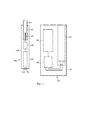
на фиг. 2 показана схематическая иллюстрация компоновки электрических контактов на электрически управляемом курительном устройстве, показанном на фиг. 1; иin fig. 2 shows a schematic illustration of the arrangement of electrical contacts on an electrically controlled smoking device shown in FIG. one; and
на фиг. 3 показана принципиальная схема схемы защиты от короткого замыкания для устройства типа, проиллюстрированного на фиг. 1 и 2.in fig. 3 is a circuit diagram of a short circuit protection circuit for a device of the type illustrated in FIG. 1 and 2.
На фиг. 1 показана система, включающая зарядное устройство 100 и перезаряжаемое устройство 102, в соответствии с одним вариантом осуществления изобретения. Зарядное устройство 100 в данном примере представляет собой зарядный блок для электрически нагреваемой курительной системы. Перезаряжаемое устройство 102 в данном примере представляет собой электрически нагреваемое устройство, генерирующее аэрозоль, выполненное с возможностью вмещения курительного изделия 104, содержащего субстрат, образующий аэрозоль. Перезаряжаемое устройство содержит нагреватель для нагрева субстрата, образующего аэрозоль, во время работы. Пользователь осуществляет затяжку через мундштучную часть курительного изделия 104 для втягивания аэрозоля в рот пользователя. Перезаряжаемое устройство 102 выполнено с возможностью размещения внутри полости 112 в зарядном устройстве 100 с целью перезарядки источника питания в перезаряжаемом устройстве.FIG. 1 shows a system comprising a
Зарядное устройство 100 содержит первую батарею 106, управляющую электронику 108 и электрические контакты 110, выполненные с возможностью подачи электропитания на вторую батарею в перезаряжаемом устройстве и подачи электрических данных на электронику 128 в перезаряжаемом устройстве от первой батареи 106, если перезаряжаемое устройство соединено с электрическими контактами 110. Электрические контакты 110 предоставлены смежно с дном полости 112. Полость выполнена с возможностью вмещения перезаряжаемого устройства 102. Компоненты зарядного устройства 100 расположены в корпусе 116.
Перезаряжаемое устройство 102 содержит вторую батарею 126, вторичную управляющую электронику 128 и электрические контакты 130. Как описано выше, перезаряжаемое устройство 102 выполнено с возможностью приема подаваемого питания и данных от зарядного устройства, когда электрические контакты 130 контактируют с электрическими контактами 110 зарядного устройства 100. Перезаряжаемое устройство 102 дополнительно содержит полость 132, выполненную с возможностью вмещения курительного изделия 104. На дне полости 132 предоставлен нагреватель 134, например, нагреватель в форме лезвия. При использовании пользователь активирует перезаряжаемое устройство 102 и питание подается от батареи 126 через управляющую электронику 128 на нагреватель 134. Нагреватель нагревается до стандартной рабочей температуры, достаточной для генерирования аэрозоля из субстрата, образующего аэрозоль, изделия 104, генерирующего аэрозоль. Компоненты перезаряжаемого устройства 102 расположены в корпусе 136. Перезаряжаемое устройство данного типа описано более подробно, например, в документе EP2110033.The
В данном примере перезаряжаемое устройство 102 представляет собой электрически нагреваемое курительное устройство. Таким образом, перезаряжаемое устройство 102 является небольшим (имеет размер традиционной сигареты). Перезаряжаемое устройство 102 имеет многоугольное поперечное сечение. Наружный диаметр перезаряжаемого устройства может составлять от приблизительно 12,7 мм до приблизительно 13,65 мм при измерении от плоской внешней поверхности до противоположной плоской внешней поверхности; от приблизительно 13,4 мм до приблизительно 14,2 мм при измерении от кромки до противоположной кромки (т.е. от линии пересечения двух внешних поверхностей с одной стороны перезаряжаемого устройства до соответствующей линии пересечения с другой стороны); и от приблизительно 14,2 мм до приблизительно 15 мм при измерении от верхней поверхности кнопки до противоположной нижней плоской внешней поверхности. Длина перезаряжаемого устройства составляет приблизительно 80 мм.In this example, the
Курительное устройство должно подавать высокую мощность в течение периода времени, равного лишь нескольким минутам, как правило, приблизительно 7 минутам, в процессе одного сеанса курения. Затем может потребоваться возврат второй батареи в зарядное устройство 100 для перезарядки. Первая батарея 106 в зарядном устройстве выполнена с возможностью хранения заряда, достаточного для многократной перезарядки второй батареи 126 до тех пор, пока не потребуется ее собственная перезарядка. Таким образом для пользователя обеспечена портативная система, которая обеспечивает возможность выполнения множества сеансов курения до тех пор, пока не потребуется перезарядка через электрическую розетку.The smoking device should supply high power for a period of only a few minutes, typically about 7 minutes, during a single smoking session. Then you may need to return the second battery to the
Для того, чтобы вторая батарея 126 удовлетворяла противоречивым требованиям в отношении малого размера, достаточной емкости и безопасной, но быстрой зарядки и разрядки, а также приемлемого срока службы, может использоваться литий-железо-фосфатная (LiFePO4) батарея, как в данном примере. Вторая батарея 126 в данном примере имеет цилиндрическую форму с диаметром 10 мм и длиной 37 мм. В альтернативном варианте, в качестве второй батареи может использоваться литий-титанатная батарея.In order for the
Первая батарея 106 в зарядном устройстве 100 представляет собой литий-кобальт-оксидную (LiCoO2) батарею призматического типа. Литий-кобальт-оксидная батарея обеспечивает более высокое напряжение батареи, чем литий-железо-фосфатная батарея, что обеспечивает возможность зарядки литий-железо-фосфатной батареи от одной литий-кобальт-оксидной батареи.The
Субстрат, образующий аэрозоль, предпочтительно содержит табакосодержащий материал, содержащий летучие ароматические соединения табака, которые высвобождаются из субстрата при нагреве. В качестве альтернативы, субстрат, образующий аэрозоль, может содержать нетабачный материал. Предпочтительно, субстрат, образующий аэрозоль, дополнительно содержит вещество для образования аэрозоля. Примерами подходящих веществ для образования аэрозоля являются глицерин и пропиленгликоль.The aerosol-forming substrate preferably contains tobacco-containing material containing volatile aromatic tobacco compounds that are released from the substrate when heated. Alternatively, the aerosol forming substrate may contain non-tobacco material. Preferably, the aerosol forming substrate further comprises a substance for aerosol formation. Examples of suitable substances for aerosol formation are glycerin and propylene glycol.
Субстрат, образующий аэрозоль, может представлять собой твердый субстрат. Твердый субстрат может содержать, например, одно или несколько из следующего: порошок, гранулы, шарики, кусочки, тонкие трубочки, полоски или листы, содержащие одно или несколько из следующего: травяные листья, табачные листья, фрагменты табачных жилок, восстановленный табак, гомогенизированный табак, экструдированный табак и взорванный табак. В качестве альтернативы, субстрат, образующий аэрозоль, может представлять собой жидкий субстрат и курительное изделие может содержать средства для удержания жидкого субстрата.The aerosol forming substrate may be a solid substrate. A solid substrate may contain, for example, one or more of the following: powder, granules, pellets, pieces, thin tubes, strips or sheets containing one or more of the following: herbal leaves, tobacco leaves, tobacco vein fragments, reconstituted tobacco, homogenized tobacco extruded tobacco and blown up tobacco. Alternatively, the aerosol forming substrate may be a liquid substrate and the smoking article may contain means for holding the liquid substrate.
На фиг. 2 показана схематическая иллюстрация компоновки электрических контактов на электрически управляемом курительном устройстве и зарядном устройстве, показанных на фиг. 1. На фиг. 2 показано, что перезаряжаемое устройство 102 имеет пять симметрично расположенных электрических контактов 131, 133, 135, 137, 139. Два контакта предоставлены для питания, два контакта предоставлены для данных и один контакт резервный. Из двух контактов, предоставленных для питания, первый контакт 131 выполнен с возможностью приема напряжения зарядки и второй контакт 133 выполнен в качестве электрического заземления. Зарядное устройство имеет соответствующие компоновки контактов 111, 113, 115, 117, 119 для зацепления с контактами на перезаряжаемом устройстве.FIG. 2 shows a schematic illustration of the arrangement of electrical contacts on an electrically controlled smoking device and a charging device shown in FIG. 1. In FIG. 2 shows that the
В случае компоновки, которая, например, показана на фиг. 2, существует вероятность короткого замыкания между первым контактом 131 и вторым контактом 133 или одним из контактов 135 или 137 передачи данных. Для предотвращения перегрева батареи в случае короткого замыкания предоставляется компоновка для защиты от короткого замыкания.In the case of the arrangement, which, for example, is shown in FIG. 2, there is a possibility of a short circuit between the
На фиг. 3 проиллюстрирована компоновка для защиты от короткого замыкания в соответствии с одним вариантом осуществления. Первый контакт 131 показан с правой стороны на фиг. 3. Соединение со второй батареей 126 показано выводом 200. P-канальный MOSFET 210 включен между первым контактом 131 и второй батареей 126. Исток MOSFET 211 соединен с первым контактом 131 и сток 213 соединен со второй батареей. MOSFET 210 «включен» и будет обеспечивать протекание тока от истока к стоку, если напряжение на истоке (от зарядного устройства) превышает напряжение на стоке (второй батарее 126). Если напряжение на стоке становится равным или превышающим напряжение на истоке, тогда ток не будет протекать. В данном варианте осуществления MOSFET представляет собой DMP1022UFDE-7 MOSFET, выпускаемый компанией Diodes Inc., который имеет сопротивление в режиме насыщения 21,5 мОм и имеет размер корпуса 2 мм × 2 мм.FIG. 3 illustrates an arrangement for short circuit protection in accordance with one embodiment. The
В данном примере система выполнена с возможностью быстрой зарядки второй батареи 126 со скоростью от 8 до 10 Кл. Для быстрой зарядки с данной скоростью используется фаза зарядки при постоянном токе с последующей фазой зарядки при постоянном напряжении. Для гарантирования того, что во время зарядки, когда MOSFET включен, он имеет малое сопротивление и, следовательно, приводит к низким потерям энергии, схема, показанная на фиг. 3, работает посредством усиления напряжения от истока к стоку и его подачи на затвор 215 с коэффициентом усиления, выбранным таким образом, что падение, вызванное MOSFET во время фазы постоянного тока, является достаточным для работы MOSFET в режиме насыщения. В данном примере постоянный ток во время фазы постоянного тока составляет приблизительно 1 А. При меньших токах менее приблизительно 0,6 А во время фазы постоянного напряжения MOS-FET, например, будет работать в линейной области. Схема управления, описанная далее и показанная на фиг. 3, затем регулирует падение напряжения от истока к стоку, но всегда с низкими потерями.In this example, the system is designed with the ability to quickly charge the
Зарядка со скоростью от 8 до 10 Кл намного быстрее типовой скорости зарядки и конечно же можно выбрать компоненты для обеспечения более высокого коэффициента усиления, так что MOSFET работает в режиме насыщения при намного меньшем токе зарядки, если предполагается, что он является типовым режимом работы для устройства.Charging at speeds from 8 to 10 Kl is much faster than a typical charging rate and of course you can select components to provide higher gain, so the MOSFET works in saturation mode with a much lower charging current if it is assumed to be a typical operating mode for the device .
Для усиления напряжения от истока к стоку используется операционный усилитель 212. В данном варианте осуществления операционный усилитель 212 представляет собой OPA369, выпускаемый компанией Texas Instruments.To amplify the voltage from source to drain, an
Коэффициент усиления, необходимый для операционного усилителя, определяется следующим образом:The gain required for the operational amplifier is determined as follows:
Максимальное необходимое напряжение затвора для извлечения пользы из малого сопротивления MOSFET в режиме насыщения, иMaximum required gate voltage to benefit from low MOSFET resistance in saturation mode, and
Падение напряжения между истоком и стоком.The voltage drop between the source and drain.
В данном варианте осуществления рабочее напряжение затвора составляет VGS=-3,0 В. Сопротивление MOSFET с данным напряжением затвора (RDSON) имеет типовое значение 14 мОм. Для номинального тока зарядки 1,0 А, который приводит к падению напряжения в 14 мВ на MOSFET 210. Необходимый коэффициент усиления операционного усилителя 212 следовательно составляет приблизительно:In this embodiment, the gate operating voltage is VGS = -3.0 V. The MOSFET resistance with this gate voltage (RDSON) has a typical value of 14 mΩ. For a rated charging current of 1.0 A, which leads to a voltage drop of 14 mV on the
![]()
![]()
Коэффициент усиления инвертирующего усилителя задается отношением сопротивления между резистором 214 и резистором 216.The gain of the inverting amplifier is given by the resistance ratio between
В случае короткого замыкания заряд от перезаряжаемой батареи будет протекать через резистор 214. Следовательно, резистор 214 выбирается таким образом, чтобы гарантировать, что в случае короткого замыкания протекает малый ток, в идеале менее 1 мА. Максимальное напряжение U батареи составляет 3,65 Вольта. Значение 10 кОм выбирается для резистора 214, который обеспечивает следующий ток:In the event of a short circuit, the charge from the rechargeable battery will flow through the
![]()
![]()
Данное значение ниже ограничения в 1 мА и, следовательно, соответствует данному требованию.This value is below the limit of 1 mA and therefore meets this requirement.
Сопротивление резистора 216 затем определяет коэффициент усиления. В данном варианте осуществления значение 47 Ом выбирается для предоставления следующего коэффициента усиления:The resistance of the
![]()
![]()
Данное значение 212,7 является близким к значению 214,3, вычисленному выше. Следовательно, если перезаряжаемое устройство должным образом соединено с зарядным устройством, MOSFET 210 включен и имеет малое сопротивление. Если возникает короткое замыкание и напряжение на контакте 311 зарядки идет на заземление, MOSFET 210 выключается и через него не протекает ток.This value of 212.7 is close to the value of 214.3, calculated above. Therefore, if the rechargeable device is properly connected to the charger, the
Небольшое смещение, вносимое резистором 218, гарантирует, что MOSFET 210 должным образом закрыт, когда напряжение истока и напряжение стока равны, что случается, когда напряжение зарядки не подается на контактную площадку и когда напряжение батареи подается на вход через резистор 214 для обеспечения считывания напряжения батареи на зарядной площадке. Наличие резистора 218 гарантирует, что имеется небольшое падение напряжения на резисторе 216 в данных условиях. Это в свою очередь гарантирует, что напряжение на отрицательном входе операционного усилителя меньше напряжения на положительном входе операционного усилителя на величину, которая превышает любое внутреннее смещение внутри операционного усилителя. Значение сопротивления 1 МОм выбирается для резистора 218. Это гарантирует, что резистор 218 смещения приводит к тому, что очень малый дополнительный ток холостого хода потребляется схемой, и гарантирует лишь небольшое дополнительное падение напряжения на резисторе 216 во время обычной работы.The small offset introduced by
Резистор 220 затвора препятствует тому, чтобы операционный усилитель воспринимал емкостную нагрузку из-за емкости затвора MOSFET 210. Большие емкостные нагрузки могут привести к пикам тока, которые превышают выходной ток короткого замыкания операционного усилителя. Выбранное значение 1 кОм для резистора 220 затвора удерживает пик тока ниже определенного выходного тока короткого замыкания операционного усилителя во всех случаях.The
Резистор 222 представляет собой нагрузочный резистор, который гарантирует, что напряжение затвора удерживается близким к напряжению истока и, следовательно, MOSFET закрыт, даже если выход операционного усилителя отключен. Это может происходить, если напряжение батареи падает ниже минимального напряжения источника питания для операционного усилителя на 1,8 В. Резистор 222 имеет значение сопротивления в 10 кОм в данном примере.
Как было объяснено, если перезаряжаемое устройство должным образом соединено с зарядным устройством во время фазы зарядки при постоянном токе, напряжение затвора MOSFET 210 является достаточным для работы MOSFET в режиме насыщения с очень малым сопротивлением и, следовательно, очень низкими потерями энергии.As explained, if the rechargeable device is properly connected to the charger during the charging phase at a constant current, the gate voltage of the
Если перезаряжаемое устройство отключено от зарядного устройства и отсутствует соединение на контактах зарядки, MOSFET выключается и ток не может протекать через него. Если возникает короткое замыкание между контактами зарядки, MOSFET остается выключенным и ток не протекает через MOSFET. В случае возникновения короткого замыкания лишь слабый ток менее 1 мА может протекать через резистор 214.If the rechargeable device is disconnected from the charger and there is no connection at the charging pins, the MOSFET turns off and no current can flow through it. If a short circuit occurs between the charging contacts, the MOSFET remains off and no current flows through the MOSFET. In the event of a short circuit, only a weak current of less than 1 mA can flow through the
Вышеописанный приведенный в качестве примера вариант осуществления является иллюстративным, а не ограничивающим. На основании рассмотренного выше приведенного в качестве примера варианта осуществления другие варианты осуществления, соответствующие вышеуказанному приведенному в качестве примера варианту осуществления, теперь будут понятны специалисту в данной области техники.The above exemplary embodiment is illustrative and not restrictive. Based on the above example embodiment, as described above, other embodiments corresponding to the above example embodiment will now be understood by a person skilled in the art.
Claims (12)
Applications Claiming Priority (3)
| Application Number | Priority Date | Filing Date | Title |
|---|---|---|---|
| EP14180991 | 2014-08-14 | ||
| EP14180991.3 | 2014-08-14 | ||
| PCT/EP2015/066576 WO2016023711A1 (en) | 2014-08-14 | 2015-07-20 | Rechargeable device with short circuit prevention |
Publications (3)
| Publication Number | Publication Date |
|---|---|
| RU2017108156A RU2017108156A (en) | 2018-09-14 |
| RU2017108156A3 RU2017108156A3 (en) | 2019-02-21 |
| RU2685248C2 true RU2685248C2 (en) | 2019-04-17 |
Family
ID=51383557
Family Applications (1)
| Application Number | Title | Priority Date | Filing Date |
|---|---|---|---|
| RU2017108156A RU2685248C2 (en) | 2014-08-14 | 2015-07-20 | Rechargeable device with short circuit prevention |
Country Status (15)
| Country | Link |
|---|---|
| US (1) | US10326289B2 (en) |
| EP (1) | EP3180831B1 (en) |
| JP (1) | JP6822945B2 (en) |
| KR (1) | KR102371881B1 (en) |
| CN (1) | CN106572701B (en) |
| AR (1) | AR101939A1 (en) |
| CA (1) | CA2954813A1 (en) |
| ES (1) | ES2690846T3 (en) |
| IL (1) | IL249723A0 (en) |
| MX (1) | MX364496B (en) |
| PL (1) | PL3180831T3 (en) |
| PT (1) | PT3180831T (en) |
| RU (1) | RU2685248C2 (en) |
| TW (1) | TW201607193A (en) |
| WO (1) | WO2016023711A1 (en) |
Cited By (1)
| Publication number | Priority date | Publication date | Assignee | Title |
|---|---|---|---|---|
| RU2738703C1 (en) * | 2019-05-31 | 2020-12-15 | Джапан Тобакко Инк. | Aerosol inhaler control device and aerosol inhaler |
Families Citing this family (31)
| Publication number | Priority date | Publication date | Assignee | Title |
|---|---|---|---|---|
| US10244793B2 (en) | 2005-07-19 | 2019-04-02 | Juul Labs, Inc. | Devices for vaporization of a substance |
| US10279934B2 (en) | 2013-03-15 | 2019-05-07 | Juul Labs, Inc. | Fillable vaporizer cartridge and method of filling |
| KR102256889B1 (en) | 2013-12-23 | 2021-05-31 | 쥴 랩스, 인크. | Vaporization device systems and methods |
| US10076139B2 (en) | 2013-12-23 | 2018-09-18 | Juul Labs, Inc. | Vaporizer apparatus |
| USD842536S1 (en) | 2016-07-28 | 2019-03-05 | Juul Labs, Inc. | Vaporizer cartridge |
| USD825102S1 (en) | 2016-07-28 | 2018-08-07 | Juul Labs, Inc. | Vaporizer device with cartridge |
| US20160366947A1 (en) | 2013-12-23 | 2016-12-22 | James Monsees | Vaporizer apparatus |
| US10159282B2 (en) | 2013-12-23 | 2018-12-25 | Juul Labs, Inc. | Cartridge for use with a vaporizer device |
| US10058129B2 (en) | 2013-12-23 | 2018-08-28 | Juul Labs, Inc. | Vaporization device systems and methods |
| KR102627987B1 (en) | 2014-12-05 | 2024-01-22 | 쥴 랩스, 인크. | Calibrated dose control |
| WO2016183002A1 (en) * | 2015-05-12 | 2016-11-17 | John Cameron | Electrical power supply for an electronic vapor device |
| DE202017007467U1 (en) | 2016-02-11 | 2021-12-08 | Juul Labs, Inc. | Fillable vaporizer cartridge |
| EP3419443A4 (en) | 2016-02-11 | 2019-11-20 | Juul Labs, Inc. | Securely attaching cartridges for vaporizer devices |
| US10405582B2 (en) | 2016-03-10 | 2019-09-10 | Pax Labs, Inc. | Vaporization device with lip sensing |
| USD844892S1 (en) * | 2016-03-28 | 2019-04-02 | Brian K. Reaux | Cannabis container |
| USD849996S1 (en) | 2016-06-16 | 2019-05-28 | Pax Labs, Inc. | Vaporizer cartridge |
| CN105876872B (en) * | 2016-06-17 | 2018-10-26 | 深圳瀚星翔科技有限公司 | Electronic cigarette working efficiency in a low voltage state promotes circuit and its method |
| USD851830S1 (en) | 2016-06-23 | 2019-06-18 | Pax Labs, Inc. | Combined vaporizer tamp and pick tool |
| USD836541S1 (en) | 2016-06-23 | 2018-12-25 | Pax Labs, Inc. | Charging device |
| US10051893B2 (en) * | 2016-07-25 | 2018-08-21 | Fontem Holdings 1 B.V. | Apparatus and method for communication and negotiation of charge rate between electronic smoking device and charger |
| US10593927B2 (en) | 2017-04-28 | 2020-03-17 | Microsoft Technology Licensing, Llc | Battery output disable when unconnected |
| CN109283992B (en) * | 2017-07-21 | 2020-09-29 | 华为终端有限公司 | Bidirectional power supply protection circuit |
| USD887632S1 (en) | 2017-09-14 | 2020-06-16 | Pax Labs, Inc. | Vaporizer cartridge |
| JP6853388B2 (en) * | 2018-02-02 | 2021-03-31 | 日本たばこ産業株式会社 | Method of selecting the electrical resistance value of the known resistance in the power supply unit of the suction component generator and the power supply unit of the suction component generator |
| PL3530130T3 (en) * | 2018-02-27 | 2021-05-04 | Imperial Tobacco Ventures Limited | Smoking apparatus |
| CN108451036B (en) * | 2018-03-20 | 2020-09-15 | 常州市派腾电子技术服务有限公司 | Electronic cigarette control device, method, electronic cigarette and computer storage medium |
| KR102544099B1 (en) * | 2018-03-26 | 2023-06-15 | 니뽄 다바코 산교 가부시키가이샤 | Aerosol generating device and control method and storage medium |
| GB201814202D0 (en) * | 2018-08-31 | 2018-10-17 | Nicoventures Trading Ltd | A resonant circuit for an aerosol generating system |
| JP6609687B1 (en) * | 2018-12-27 | 2019-11-20 | 日本たばこ産業株式会社 | Power supply unit for aerosol inhaler, its control method and control program |
| KR102252453B1 (en) * | 2019-04-19 | 2021-05-14 | 주식회사 케이티앤지 | Method for maintaining stability of an aerosol generating apparatus by using hardware reset and apparatus thereof |
| CN110690751B (en) * | 2019-11-17 | 2021-10-01 | 鲨湾科技(上海)有限公司 | Charging base and charging system |
Citations (3)
| Publication number | Priority date | Publication date | Assignee | Title |
|---|---|---|---|---|
| US20060120069A1 (en) * | 2004-12-07 | 2006-06-08 | Mag Instrument, Inc. | Circuitry for portable lighting devices and portable rechargeable electronic devices |
| US20080239603A1 (en) * | 2007-03-27 | 2008-10-02 | Eaglepicher Energy Products Corporation | Battery protection circuit for lithium cabon monofluoride battery |
| RU2472270C2 (en) * | 2007-11-27 | 2013-01-10 | Тамура Корпорейшн | Charging circuit for secondary accumulator battery |
Family Cites Families (24)
| Publication number | Priority date | Publication date | Assignee | Title |
|---|---|---|---|---|
| JPS5926662Y2 (en) * | 1979-02-27 | 1984-08-02 | 三洋電機株式会社 | FM receiver tuning display device |
| JPS55159416U (en) * | 1979-04-27 | 1980-11-15 | ||
| JPS55155597A (en) * | 1979-05-21 | 1980-12-03 | Mitsubishi Electric Corp | Overexcitation protective device for generator |
| EP0687067A3 (en) | 1994-06-06 | 1997-11-19 | Eaton Corporation | Short circuit protector for an isolated power MOSFET output stage |
| JPH0896779A (en) | 1994-09-22 | 1996-04-12 | Toshiba Battery Co Ltd | Battery with short circuit preventing function |
| US5539299A (en) | 1994-10-31 | 1996-07-23 | Motorola Inc. | Protection switch for a battery powered device |
| JPH1013197A (en) * | 1996-06-18 | 1998-01-16 | Mitsubishi Electric Corp | Sawtooth wave generation circuit |
| DE19635332A1 (en) | 1996-08-30 | 1998-03-12 | Siemens Ag | Power transistor with short-circuit protection by voltage regulator |
| US6031702A (en) | 1997-10-22 | 2000-02-29 | Siliconix Incorporated | Short circuit protected DC-DC converter using disconnect switching and method of protecting load against short circuits |
| US6835491B2 (en) | 1998-04-02 | 2004-12-28 | The Board Of Trustees Of The University Of Illinois | Battery having a built-in controller |
| JP2002335626A (en) * | 2001-05-10 | 2002-11-22 | Nec System Technologies Ltd | Reverse current protection circuit |
| US6844705B2 (en) * | 2002-12-09 | 2005-01-18 | Intersil Americas Inc. | Li-ion/Li-polymer battery charger configured to be DC-powered from multiple types of wall adapters |
| JP4149373B2 (en) | 2003-12-26 | 2008-09-10 | Tdk株式会社 | Short circuit protection circuit |
| KR101060141B1 (en) * | 2004-08-23 | 2011-08-30 | 세미컨덕터 콤포넨츠 인더스트리즈 엘엘씨 | Battery protection method and structure |
| CN103279181A (en) * | 2007-08-28 | 2013-09-04 | Commvault系统公司 | Power management of data processing resources, such as power adaptive management of data storage operations |
| JP5144177B2 (en) * | 2007-08-31 | 2013-02-13 | キヤノン株式会社 | Information processing device |
| JP5030817B2 (en) * | 2008-02-29 | 2012-09-19 | 東洋電機製造株式会社 | Voltage duty ratio conversion circuit |
| EP2100525A1 (en) * | 2008-03-14 | 2009-09-16 | Philip Morris Products S.A. | Electrically heated aerosol generating system and method |
| EP2110034A1 (en) * | 2008-04-17 | 2009-10-21 | Philip Morris Products S.A. | An electrically heated smoking system |
| CN103001179B (en) | 2011-09-08 | 2016-03-30 | 海洋王照明科技股份有限公司 | A kind of LED lamp and short-circuit protection circuit thereof |
| JP5919506B2 (en) * | 2011-09-20 | 2016-05-18 | パナソニックIpマネジメント株式会社 | Rechargeable electrical equipment |
| CN102570412B (en) | 2011-12-29 | 2014-11-05 | 航天时代电子技术股份有限公司 | DC solid-state power controller |
| EP2701268A1 (en) * | 2012-08-24 | 2014-02-26 | Philip Morris Products S.A. | Portable electronic system including charging device and method of charging a secondary battery |
| US9276421B2 (en) * | 2012-10-31 | 2016-03-01 | Motorola Solutions, Inc. | Portable rechargeable battery pack and external adapter for same |
-
2015
- 2015-07-16 TW TW104123025A patent/TW201607193A/en unknown
- 2015-07-20 PL PL15738113T patent/PL3180831T3/en unknown
- 2015-07-20 ES ES15738113.8T patent/ES2690846T3/en active Active
- 2015-07-20 RU RU2017108156A patent/RU2685248C2/en active
- 2015-07-20 CA CA2954813A patent/CA2954813A1/en not_active Abandoned
- 2015-07-20 WO PCT/EP2015/066576 patent/WO2016023711A1/en active Application Filing
- 2015-07-20 CN CN201580042977.2A patent/CN106572701B/en active Active
- 2015-07-20 MX MX2017002046A patent/MX364496B/en active IP Right Grant
- 2015-07-20 KR KR1020177002186A patent/KR102371881B1/en active IP Right Grant
- 2015-07-20 PT PT15738113T patent/PT3180831T/en unknown
- 2015-07-20 EP EP15738113.8A patent/EP3180831B1/en active Active
- 2015-07-20 US US15/502,053 patent/US10326289B2/en active Active
- 2015-07-20 JP JP2017506758A patent/JP6822945B2/en active Active
- 2015-08-13 AR ARP150102617A patent/AR101939A1/en active IP Right Grant
-
2016
- 2016-12-22 IL IL249723A patent/IL249723A0/en unknown
Patent Citations (3)
| Publication number | Priority date | Publication date | Assignee | Title |
|---|---|---|---|---|
| US20060120069A1 (en) * | 2004-12-07 | 2006-06-08 | Mag Instrument, Inc. | Circuitry for portable lighting devices and portable rechargeable electronic devices |
| US20080239603A1 (en) * | 2007-03-27 | 2008-10-02 | Eaglepicher Energy Products Corporation | Battery protection circuit for lithium cabon monofluoride battery |
| RU2472270C2 (en) * | 2007-11-27 | 2013-01-10 | Тамура Корпорейшн | Charging circuit for secondary accumulator battery |
Cited By (1)
| Publication number | Priority date | Publication date | Assignee | Title |
|---|---|---|---|---|
| RU2738703C1 (en) * | 2019-05-31 | 2020-12-15 | Джапан Тобакко Инк. | Aerosol inhaler control device and aerosol inhaler |
Also Published As
| Publication number | Publication date |
|---|---|
| US20170229885A1 (en) | 2017-08-10 |
| RU2017108156A3 (en) | 2019-02-21 |
| CA2954813A1 (en) | 2016-02-18 |
| RU2017108156A (en) | 2018-09-14 |
| WO2016023711A1 (en) | 2016-02-18 |
| US10326289B2 (en) | 2019-06-18 |
| KR102371881B1 (en) | 2022-03-08 |
| PT3180831T (en) | 2018-12-17 |
| CN106572701B (en) | 2020-07-03 |
| PL3180831T3 (en) | 2019-05-31 |
| IL249723A0 (en) | 2017-02-28 |
| JP2017527249A (en) | 2017-09-14 |
| EP3180831A1 (en) | 2017-06-21 |
| AR101939A1 (en) | 2017-01-25 |
| TW201607193A (en) | 2016-02-16 |
| EP3180831B1 (en) | 2018-09-12 |
| ES2690846T3 (en) | 2018-11-22 |
| JP6822945B2 (en) | 2021-01-27 |
| MX364496B (en) | 2019-04-29 |
| KR20170042285A (en) | 2017-04-18 |
| CN106572701A (en) | 2017-04-19 |
| MX2017002046A (en) | 2017-05-23 |
Similar Documents
| Publication | Publication Date | Title |
|---|---|---|
| RU2685248C2 (en) | Rechargeable device with short circuit prevention | |
| KR102603409B1 (en) | Electric aerosol generation system with rechargeable power source | |
| JP6845131B2 (en) | Adaptive Battery Charging Methods and Systems | |
| EP3175507B1 (en) | E-cigarette and re-charging pack | |
| WO2016119694A1 (en) | Battery protection circuit, electrical energy providing device and electronic device | |
| US20150180245A1 (en) | Portable rechargeable battery pack and external adapter for same | |
| EP2701268A1 (en) | Portable electronic system including charging device and method of charging a secondary battery | |
| GB2559281A (en) | E-cigarette and re-charging pack | |
| CN112532048B (en) | Power supply equipment wake-up circuit | |
| TW201206012A (en) | Battery state monitoring circuit and battery device | |
| JP2019106870A5 (en) | Rechargeable battery protection integrated circuit | |
| TW201217813A (en) | Battery state monitoring circuit and battery device | |
| US6636020B1 (en) | Lithium-ion over voltage protection circuit | |
| CN106253455B (en) | A kind of power supply circuit | |
| TW200814486A (en) | Power supplying system with remote-controlling circuit and method for operating a power supplying system | |
| JP2009239989A (en) | Charger | |
| GB2566857B (en) | E-cigarette and re-charging pack | |
| CN202798057U (en) | Manually switched battery circuit | |
| CN105914821B (en) | Control circuit of portable power source and group battery | |
| TW200849697A (en) | Protection circuit for battery charge | |
| TW490904B (en) | Automatic cut-off for operation control of temperature control switch and transient holding-type charging circuit for wide voltage variation range | |
| GB2566856B (en) | E-cigarette and re-charging pack | |
| CN114631651A (en) | Battery protection circuit, battery pack and electron cigarette | |
| TW200525850A (en) | Smart over current protective circuit | |
| GB2566858A (en) | E-cigarette and re-charging pack |