RU2676455C2 - Multi-functional modular shock absorber of motor mounting support - Google Patents
Multi-functional modular shock absorber of motor mounting support Download PDFInfo
- Publication number
- RU2676455C2 RU2676455C2 RU2015152223A RU2015152223A RU2676455C2 RU 2676455 C2 RU2676455 C2 RU 2676455C2 RU 2015152223 A RU2015152223 A RU 2015152223A RU 2015152223 A RU2015152223 A RU 2015152223A RU 2676455 C2 RU2676455 C2 RU 2676455C2
- Authority
- RU
- Russia
- Prior art keywords
- engine
- housing
- shaft
- mounting support
- frame
- Prior art date
Links
Images
Classifications
-
- A—HUMAN NECESSITIES
- A61—MEDICAL OR VETERINARY SCIENCE; HYGIENE
- A61C—DENTISTRY; APPARATUS OR METHODS FOR ORAL OR DENTAL HYGIENE
- A61C17/00—Devices for cleaning, polishing, rinsing or drying teeth, teeth cavities or prostheses; Saliva removers; Dental appliances for receiving spittle
- A61C17/16—Power-driven cleaning or polishing devices
- A61C17/22—Power-driven cleaning or polishing devices with brushes, cushions, cups, or the like
- A61C17/32—Power-driven cleaning or polishing devices with brushes, cushions, cups, or the like reciprocating or oscillating
- A61C17/34—Power-driven cleaning or polishing devices with brushes, cushions, cups, or the like reciprocating or oscillating driven by electric motor
-
- H—ELECTRICITY
- H02—GENERATION; CONVERSION OR DISTRIBUTION OF ELECTRIC POWER
- H02K—DYNAMO-ELECTRIC MACHINES
- H02K33/00—Motors with reciprocating, oscillating or vibrating magnet, armature or coil system
-
- H—ELECTRICITY
- H02—GENERATION; CONVERSION OR DISTRIBUTION OF ELECTRIC POWER
- H02K—DYNAMO-ELECTRIC MACHINES
- H02K5/00—Casings; Enclosures; Supports
- H02K5/24—Casings; Enclosures; Supports specially adapted for suppression or reduction of noise or vibrations
-
- H—ELECTRICITY
- H02—GENERATION; CONVERSION OR DISTRIBUTION OF ELECTRIC POWER
- H02K—DYNAMO-ELECTRIC MACHINES
- H02K7/00—Arrangements for handling mechanical energy structurally associated with dynamo-electric machines, e.g. structural association with mechanical driving motors or auxiliary dynamo-electric machines
- H02K7/14—Structural association with mechanical loads, e.g. with hand-held machine tools or fans
- H02K7/145—Hand-held machine tool
Abstract
Description
[0001] Аспекты настоящего изобретения относятся в целом к зубным щеткам с электрическим приводом. В частности, изобретение относится к элементам зубной щетки, которые способствуют большей долговечности и управлению вибрациями, передаваемыми пользователю через ручку зубной щетки.[0001] Aspects of the present invention relate generally to electric toothbrushes. In particular, the invention relates to toothbrush elements that contribute to greater durability and control of vibrations transmitted to the user through the handle of the toothbrush.
[0002] Электрические зубные щетки в целом хорошо известны и включают в себя множество конструкций и физических конфигураций. Множество электрических зубных щеток имеют движение вращательного типа. Некоторые имеют возможность якорного вращения на 360°, но из-за конструкционной компоновки создают колебательное движение, ограниченное определенным диапазоном движения, то есть выбранным дугообразным участком в пределах 360°, для обеспечения более подходящего чистящего эффекта. Некоторые из этих устройств вращательного движения являются механическими, другие же представляют собой резонансные системы, включающие в себя перемещаемую массу, например, конструкцию чистящей головки, и пружину, прикрепленную к ручке. В резонансной системе чистящая головка приводится в действие с частотой, относительно близкой к собственной частоте системы.[0002] Electric toothbrushes are generally well known and include many designs and physical configurations. Many electric toothbrushes have a rotational movement. Some have the ability to rotate 360 °, but due to the structural arrangement they create an oscillating movement limited by a certain range of motion, that is, a selected arcuate area within 360 °, to provide a more suitable cleaning effect. Some of these rotational motion devices are mechanical, while others are resonant systems that include a moving mass, for example, the design of the cleaning head, and a spring attached to the handle. In a resonant system, the cleaning head is driven at a frequency relatively close to the natural frequency of the system.
[0003] Существует множество способов реализации резонансной зубной щетки. Резонансные электрические зубные щетки могут использовать двигатель, имеющий качающийся якорь, например, как в зубных щетках, описанных в принадлежащем владельцу настоящей заявки патенте США № 5189751. Более современные конструкции резонирующих зубных щеток включают в себя привод, имеющий конец чистящей головки, и якорный конец, разделенные неподвижной центральной пружиной, например, описанной в принадлежащем владельцу настоящей заявки патенте США № 7627922. В первом типе используется якорь, который переносит большую часть вибрации устройства на пользователя через корпус зубной щетки. Последняя конструкция стремится к подавлению вибрации и удара посредством работы на околорезонансной частоте, на которой чистящая головка поворачивается со сдвигом по фазе на 180° относительно вращения якоря. Таким образом, приводной блок по существу вибрационно изолирован от корпуса.[0003] There are many ways to implement a resonant toothbrush. Resonant electric toothbrushes can use a motor having a swinging armature, for example, as in the toothbrushes described in US Pat. No. 5,189,751 to the owner of this application. More recent designs of resonant toothbrushes include a drive having an end of the cleaning head and an anchor end, separated by a fixed central spring, for example, described in US Pat. No. 7,627,922, which belongs to the owner of this application. An anchor is used in the first type, which transfers most of the vibration of the device wa on the user through the housing of the toothbrush. The latter design seeks to suppress vibration and shock by operating at a near-resonant frequency, at which the cleaning head rotates with a phase shift of 180 ° relative to the rotation of the armature. Thus, the drive unit is substantially vibrationally isolated from the housing.
[0004] Было установлено, что каждая из этих конструкций чистит зубы оптимальным образом при узком диапазоне сочетания динамических параметров. Оптимальное сочетание описано в патенте США № 5378153 в виде треугольной области частот и амплитуды движения чистящей головки, при этом амплитуда дополнительно определяется размером чистящей головки и амплитудой вращения вала. Патент США № 7067945 описывает параметр в виде амплитуды углового поворота вала зубной щетки, которая, как утверждается там, составляет приблизительно 11 градусов при этой геометрии чистящей головки.[0004] It was found that each of these structures brushes teeth in an optimal way with a narrow range of combinations of dynamic parameters. The optimal combination is described in US patent No. 5378153 in the form of a triangular frequency range and the amplitude of movement of the cleaning head, while the amplitude is additionally determined by the size of the cleaning head and the amplitude of rotation of the shaft. US patent No. 7067945 describes a parameter in the form of the amplitude of the angular rotation of the shaft of the toothbrush, which, as stated there, is approximately 11 degrees with this geometry of the cleaning head.
[0005] Еще более новые конструкции представляют собой резонирующую зубную щетку, имеющую приводную систему с плавающим ротором. Пример такой конструкции описан в принадлежащем владельцу данной заявки патенте США № 7876003. Двигатель в такой системе может быть аналогичен вращательному двигателю, но приводится в движение так, что вал колеблется вокруг своей оси, то есть вращательное колебание, и, необязательно, вдоль своей оси, то есть осевое колебание. "Пружина" в этом типе конструкции представляет собой блок постоянного магнита в статоре, который втягивает полюса ротора обратно в нейтральное магнитное положение при отсутствии возбуждающего сигнала.[0005] Still newer designs are a resonating toothbrush having a floating rotor drive system. An example of such a construction is described in US patent No. 7876003, which belongs to the owner of this application. An engine in such a system can be similar to a rotary engine, but is driven in such a way that the shaft oscillates about its axis, that is, rotational vibration, and, optionally, along its axis, that is, axial vibration. The "spring" in this type of design is a permanent magnet unit in the stator, which pulls the rotor poles back to the neutral magnetic position in the absence of an exciting signal.
[0006] Некоторые проблемы возникают в резонирующей зубной щетке, имеющей конструкцию, описанную в патенте 003. Во-первых, обычно в каркасах используются пластиковые части, изготовленные способом литьевого формования. Эти каркасные части должны удерживать вместе внутренние функциональные части (то есть батарею, обмотку возбуждения, блок печатной платы, приводную систему, изоляцию и т.д.). Существующие каркасы состоят из нескольких частей, изготовленных способом литьевого формования, имеющих отдельные функции. Резонансные приводные системы также используют такие каркасы из многих частей для удержания приводной системы, PCBA, батареи и обмотки возбуждения с помощью одной пластиковой части, изготовленной способом литьевого формования. Система также использует дополнительную часть для создания седла уплотнения для изоляции приводного вала при соединении с корпусом для недопущения проникновения воды. Такие конструкции не являются исключительными для изделий, использующих резонансную приводную систему, а также используются с другими электрическими зубными щетками, имеющими возвратно-поступательное или выметающее движение, а также других ручных персональных устройств, требующих изолирующих поверхностей и для торцевого уплотнения, и для радиального уплотнения. Таким образом, существует необходимость в уменьшении вибрации и шума посредством изоляции подвижных частей в недорогой и более эффективной системе.[0006] Some problems arise in a resonating toothbrush having the structure described in patent 003. First, injection molded plastic parts are typically used in frames. These frame parts must hold together the internal functional parts (i.e., battery, field coil, PCB unit, drive system, insulation, etc.). Existing frameworks consist of several parts made by injection molding having separate functions. Resonant drive systems also use such multi-part frameworks to hold the drive system, PCBA, battery, and field coil with a single plastic part made by injection molding. The system also uses an additional part to create a seal seat to isolate the drive shaft when connected to the housing to prevent water ingress. Such designs are not exclusive to products using a resonant drive system, and are also used with other electric toothbrushes that have a reciprocating or sweeping movement, as well as other hand-held personal devices that require insulating surfaces for both mechanical seal and radial seal. Thus, there is a need to reduce vibration and noise by isolating moving parts in an inexpensive and more efficient system.
[0007] Другая проблема, возникающая в конструкциях с плавающим ротором, состоит в пульсации вращающего момента. Пульсация вращающего момента представляет собой соскальзывание полюса ротора из одной ориентации относительно постоянного магнита к соседнему постоянному магниту. Соскальзывание может происходить в результате внешнего воздействия, например, удара или приложенной механической силы. Результатом соскальзывания является нежелательное положение вала в состоянии покоя и связанной с ним чистящей головки в нежелательном угловом положении, нежелательном осевом положении, или и то, и другое.[0007] Another problem arising in floating rotor designs is torque ripple. The ripple of the torque is the sliding of the rotor pole from one orientation relative to the permanent magnet to the adjacent permanent magnet. Sliding can occur as a result of an external action, for example, an impact or applied mechanical force. The result of slipping is an undesirable position of the shaft at rest and the associated cleaning head in an undesirable angular position, an undesired axial position, or both.
[0008] Еще одна возникающая проблема состоит в том, что существующие в настоящее время конструкции каркаса являются слишком дорогими.[0008] Another emerging problem is that existing frame structures are too expensive.
Для снижения стоимости посредством создания модульных частей, сопрягающихся с каркасом, необходимо, чтобы каждая часть имела несколько комплексных функций. Особенно востребована система частей, имеющих низкую стоимость, которые увеличивают надежность устройства посредством поглощения осевых ударов. Осевые удары могут, например, происходить, когда зубная щетка падает на конец вала. Дополнительным желательным результатом для этих элементов является низкая стоимость материала и сборки.To reduce costs by creating modular parts that interface with the chassis, each part must have several complex functions. Particularly in demand is the system of parts having a low cost, which increase the reliability of the device by absorbing axial impacts. Axial shocks can, for example, occur when a toothbrush falls on the end of the shaft. An additional desirable result for these elements is the low cost of material and assembly.
[0009] Настоящее изобретение обеспечивает решение для устранения недостатков предшествующего уровня техники. В одном варианте осуществления изобретения описана электрическая зубная щетка, включающая в себя корпус, каркас, расположенный в корпусе, двигатель, имеющий осциллирующий выход и расположенный на каркасе. Двигатель включает в себя вал двигателя, имеющий дистальный конец, предназначенный для приема головки зубной щетки, и проксимальный конец, отходящий от двигателя в корпусе. Упругая монтажная опора двигателя расположена вблизи двигателя и предназначена для ограничения максимального смещения вала. Монтажная опора двигателя может включать в себя амортизатор, расположенный на расстоянии от конца вала.[0009] The present invention provides a solution to eliminate the disadvantages of the prior art. In one embodiment of the invention, an electric toothbrush is described, including a housing, a frame located in the housing, an engine having an oscillating output and located on the frame. The engine includes an engine shaft having a distal end for receiving a toothbrush head, and a proximal end extending from the engine in the housing. The elastic mounting support of the engine is located near the engine and is designed to limit the maximum displacement of the shaft. The engine mount may include a shock absorber located at a distance from the shaft end.
[0010] В другом варианте осуществления изобретения описана упругая монтажная опора двигателя для электрической зубной щетки. Монтажная опора двигателя включает в себя нижний амортизатор, имеющий центральную ось и периферию, осевую упорную поверхность, расположенную на одном конце нижнего амортизатора, и один или более монтажных лапок, отходящих от периферии амортизатора в направлении вдоль центральной оси, при этом каждая монтажная лапка включает в себя поверхность сжатия, расположенную с возможностью быть в сжимающем контакте с корпусом двигателя электрической зубной щетки. Монтажная опора двигателя, как описано, обеспечивает возможность фиксации двигателя к каркасу, для поглощения вибрации, вызванной резонансной работой двигателя, и для поглощения осевого механического удара вдоль продольной оси зубной щетки.[0010] In another embodiment, an elastic motor mount for an electric toothbrush is described. The engine mounting support includes a lower shock absorber having a central axis and a periphery, an axial thrust surface located at one end of the lower shock absorber, and one or more mounting legs extending from the periphery of the shock absorber in a direction along the central axis, with each mounting foot including a compression surface located with the possibility of being in compressive contact with the motor housing of an electric toothbrush. The engine mount, as described, allows the engine to be fixed to the frame, to absorb vibration caused by resonant operation of the engine, and to absorb axial mechanical shock along the longitudinal axis of the toothbrush.
[0011] НА ЧЕРТЕЖАХ:[0011] IN THE DRAWINGS:
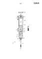
[0012] Фиг. 1 иллюстрирует блок электрической зубной щетки, включающий в себя систему для ослабления ударов и вибрации согласно одному варианту осуществления изобретения.[0012] FIG. 1 illustrates an electric toothbrush unit including a system for attenuating shock and vibration according to one embodiment of the invention.
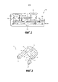
[0013] Фиг. 2 иллюстрирует эквивалентную пружинно-массовую схему блока электрической зубной щетки согласно другому аспекту изобретения.[0013] FIG. 2 illustrates an equivalent mass spring circuit of an electric toothbrush unit according to another aspect of the invention.
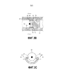
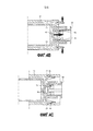
[0014] Фиг. 3A, 3B и 3C иллюстрируют упругую монтажную опору двигателя для резонирующего двигателя в электрической зубной щетке согласно другому варианту осуществления изобретения.[0014] FIG. 3A, 3B, and 3C illustrate an elastic motor mount for a resonating motor in an electric toothbrush according to another embodiment of the invention.
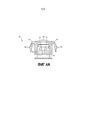
[0015] Фиг. 4A, 4B и 4C иллюстрируют многофункциональную катушку обмотки возбуждения для электрической зубной щетки согласно другому варианту осуществления изобретения.[0015] FIG. 4A, 4B and 4C illustrate a multi-function field coil for an electric toothbrush according to another embodiment of the invention.
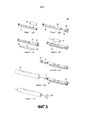
[0016] Фиг. 5 иллюстрирует способ последовательных этапов сборки электрической зубной щетки согласно еще одному варианту осуществления изобретения.[0016] FIG. 5 illustrates a method of successive steps of assembling an electric toothbrush according to yet another embodiment of the invention.
[0017] На фиг. 1 проиллюстрирован блок для электрической зубной щетки 10, включающий в себя систему смягчения механического толчка и амортизации вибрации согласно одному варианту осуществления изобретения.[0017] FIG. 1 illustrates a unit for an
[0018] Большинство компонентов электрической зубной щетки 10 содержатся в удлиненном корпусе 20, который предпочтительно имеет размеры, позволяющие удобно помещаться в руке человека. Корпус 20, предпочтительно из жесткого и легкого пластика, защищает и изолирует внутренние компоненты от удара и проникновения воды. Корпус 20 включает в себя проем на дистальном конце, то есть конце, представляющем собой дистальный конец 63 вала, и проем на проксимальном конце, то есть конце, представляющем собой заглушку 120.[0018] Most of the components of the
[0019] В корпусе 20 расположен каркас 40. Каркас 40 выполнен с возможностью удерживать большинство остальных компонентов системы, каждый из которых более подробно описан ниже. Каркас 40 может быть также выполнен из легкого жесткого или полужесткого пластика.[0019] The
[0020] Каркас 40 снабжен одной или более каркасными направляющими 42, которые сопрягаются с соответствующими прорезями вдоль внутренних стенок корпуса 20 вдоль его продольной оси. Направляющие 42 предназначены для легкой вставки каркаса 40 в проксимальный конец корпуса при сборке. Дистальный и проксимальный концы каркаса 40 соответствуют, соответственно, дистальному и проксимальному концам корпуса 20.[0020] The
[0021] В дистальный конец каркаса 40 вставлен двигатель 50. Двигатель 50 предпочтительно представляет собой резонансный двигатель, имеющий плавающий вал 60, который подвешен в осевом направлении с возможностью вращения в двигателе посредством постоянного магнитного поля. Поле предпочтительно создано постоянными магнитами, расположенными в корпусе двигателя. Дистальный конец 63 вала двигателя проходит через каркас 40 и дистальный конец корпуса 20, при этом дистальный конец 63 имеет форму, обеспечивающую прием чистящей головки или другого устройства.[0021] An
[0022] Вал 60 двигателя также проходит через кожух двигателя в направлении проксимального конца каркаса. Проксимальный конец 61 вала предпочтительно включает в себя кулачку 62 вала, функция которой более подробно описана ниже.[0022] The
[0023] Двигатель 50 удерживается в каркасе 40 двумя компонентами, монтажной опорой 70 двигателя и верхним амортизатором 44. Упругая монтажная опора 70 двигателя, предпочтительно выполненная из эластомерного материала, расположена на проксимальном конце двигателя между двигателем 50 и каркасом 40. Как более подробно описано ниже, в собранном состоянии электрической зубной щетки монтажная опора 70 двигателя расположена по оси и отстоит от проксимального конца 61 вала на расстояние "d". Монтажная опора 70 двигателя обеспечивает осевую противоударную защиту устройства, например, такую, которая вызывается нагрузкой на дистальный конец 63 вала, представленной как "F".[0023] The
[0024] При работе двигатель 50 стремится передать вибрацию на корпус 20. Вибрации могут происходить в направлении вращения вала как колебания вала, или в осевых направлениях, когда вал смещается по оси. Эти вибрации передаются руке пользователя через корпус, если они не амортизированы или не смягчены.[0024] In operation, the
[0025] Верхний амортизатор 44 зажат между дистальным концом двигателя 50 и дистальным концом каркаса 40. Верхний амортизатор 44 предпочтительно выполнен из упругого эластомерного материала, подходящего для амортизации вибрации от двигателя и защиты внутренних компонентов от внешнего удара.[0025] The
[0026] Опора 70 и верхний амортизатор 44 также действуют совместно для амортизации вращательной резонирующей вибрации между двигателем и корпусом.[0026] The
[0027] На дистальном конце между каркасом 40 и корпусом 20 зажато уплотнение 32 вала. Уплотнение 32 вала также по существу окружает вал 60. Основная функция уплотнения 32 вала состоит в недопущении проникновения воды вдоль вала 60 и дистального конца корпуса 20. Однако уплотнение 32 вала также выполняет дополнительную функцию амортизации вибрации, включающей в себя резонирующую вибрацию от двигателя.[0027] At the distal end between the
[0028] На фиг. 1 также представлены один или более аккумуляторов 80, расположенных в каркасе 40 вблизи проксимального конца корпуса. На фиг. 2 и 5 представлена управляющая печатная плата 100, которая может быть установлена на каркасе 40.[0028] In FIG. 1 also shows one or
[0029] Проксимально от батареи 80 расположена многофункциональная катушка 90 зарядной обмотки. Катушка 90 принимает проводящую обмотку, которая способствует индуктивной зарядке аккумулятора 80. Катушка 90 также имеет элементы, например, мостовидную пружину 98, представленную на фиг. 4A-4C, описанную далее, которая амортизирует боковой удар и обеспечивает сборку при отклонениях в пределах допусков. Нагрузки, приложенные катушкой 90, в целом представлены на фиг. 1 как "Fl". Катушка 90 также выполнена для удерживания каркаса 40 в корпусе 20, так что каркас 40 по существу вибрационно изолирован от корпуса 20.[0029] Maximally from the
[0030] Катушка 90 зарядной обмотки предназначена для нахождения в упругом контакте с проксимальным концом каркаса 40. Как представлено на фиг. 1, и как более подробно описано ниже в отношении фиг. 4A-4C, катушка 90 может быть сжата до размера "C" при максимальном сжатии для выполнения своих защитных функций/функций восприятия допуска. Также, как более подробно представлено на фиг 4A-4C, катушка 90 дополнительно зацепляется с внутренней стенкой проксимального конца корпуса 20 посредством ушек и прорезей или эквивалентных элементов, так что катушка 90 создает компрессионную нагрузку на каркас 40 и/или уплотнение 32 вала относительно дистального конца корпуса 20.[0030] The
[0031] Заглушка 120 расположена также на проксимальном конце корпуса 20 для защиты внутренних компонентов от удара и проникновения воды.[0031] A
[0032] Хотя узел на фиг. 1 представлен линейным, некоторые варианты осуществления могут включать в себя приводной вал, который располагается под выбранным углом к продольной оси корпуса, что обеспечивает возможность оптимального расположения чистящей головки во рту.[0032] Although the assembly of FIG. 1 is linear, some embodiments may include a drive shaft that is positioned at a selected angle to the longitudinal axis of the housing, which enables optimal placement of the cleaning head in the mouth.
[0033] Фиг. 2 иллюстрирует пружинно-массовый эквивалент 310 системы, эквивалентный узлу, представленному на фиг. 1. Эквивалент 310 представлен для дополнительной иллюстрации преимуществ узла. Ниже представлены массовые компоненты: масса 320 корпуса включает в себя корпус 20, но может также включать в себя руку пользователя. Масса 340 каркаса представлена тремя частями с целью иллюстрации своей внутренней упругости: дистальным концом 340a каркаса, серединой 340b и проксимальным концом каркаса 340c. Схема 100 управления и батарея представлены, но они не имеют особого значения для пружинно-массового эквивалента системы. Масса 350 двигателя соответствует двигателю 50. Масса 390 зарядного каркаса соответствует катушке 90 зарядной обмотки.[0033] FIG. 2 illustrates the spring-
[0034] Пружинные эквиваленты представлены ниже. Вращательная амортизация и осевая упругость верхнего амортизатора представлены пружиной 344 верхнего амортизатора. Монтажная опора 70 двигателя представлена имеющей пружину 377, 378 первой и второй монтажной лапки на проксимальном конце двигателя 350. Пружины 377/378 также обеспечивают вращательную амортизацию и осевую упругость между двигателем 350 и каркасом 340.[0034] Spring equivalents are presented below. Rotational damping and axial elasticity of the upper shock absorber are represented by the
[0035] Пружина 332 уплотнения вала обеспечивает дополнительную вращательную амортизацию и осевую упругость от двигателя/к двигателю между каркасом 340 и корпусом 320. Пружина 342 направляющей каркаса также обеспечивает некоторую вращательную амортизацию и осевую упругость между проксимальным концом 340c каркаса и корпусом 320, благодаря природной упругости в структуре каркаса между эластомерными монтажными опорами двигателя и направляющей каркаса, и также от самой монтажной конструкции направляющей каркаса, которая может включать в себя некоторый эластомерный амортизирующий материал.[0035] The
[0036] Вращательная амортизация и осевая упругость обеспечивается между проксимальным концом каркаса 340c и массой 390 зарядного каркаса посредством эквивалента 398 мостовидной пружины. Эквивалент 398 мостовидной пружины соответствует, например, участку мостовидной пружины 98 катушки 90 зарядной обмотки. И, наконец, соединительная конструкция между зарядным каркасом 390 и корпусом 320 обеспечивает пружинную функцию на соединительных пружинах 395, 396 корпуса.[0036] Rotational cushioning and axial elasticity are provided between the proximal end of the
[0037] Как можно видеть на фиг. 2, вибрации, вызванные массой 350 двигателя, могут быть изолированы от каркаса на верхнем амортизаторе 344 и лапках 377, 378 монтажной опоры двигателя. Во вторую очередь, вибрации от каркаса могут быть изолированы от руки пользователя на пружине 332 уплотнения вала, эквиваленте 398 мостовидной пружины и эквиваленте 342 пружины направляющей каркаса, а также посредством катушки 90 на первой и второй соединительных пружинах 395, 396 корпуса.[0037] As can be seen in FIG. 2, vibrations caused by the mass of the
[0038] Другой пружинный эквивалент, пружина 370 монтажной опоры двигателя между массами двигателя 350 и корпуса 320 обеспечивает защиту от осевого удара, когда вал двигателя смещается больше, чем на расстояние "d" к монтажной опоре 70 двигателя, как представлено на фиг. 1. Пружина 370 монтажной опоры двигателя соответствует нижнему амортизатору 71, дополнительно подробно описанному ниже, который расположен на монтажной опоре 70 двигателя. При действии осевой нагрузки эквиваленты 370, 398 монтажной опоры двигателя и мостовидной пружины действуют совместно на смягчение дополнительного осевого удара, возникающего от проксимального конца плавающего вала.[0038] Another spring equivalent, the
[0039] Альтернативный источник внешней силы F может прилагаться в ситуациях, когда пользователь вставляет чистящую головку на дистальный конец 63 вала. Такая приложенная сила стремится сместить плавающий вал посредством двигателя 50 и посредством каркаса 40 через корпус 20. В этой ситуации эквиваленты 370, 398 нижнего амортизатора и мостовидной пружины действуют совместно на сопротивление приложенной осевой силе. Сумма промежутка "d" и расстояния при максимальном сжатии "C" в этом случае должно быть меньше, чем расстояние сжатия эквивалентной пружины, которое требуется для прикрепления чистящей головки на вал. Это обеспечивает возможность вставки чистящей головки без создания нарушения полюсов в двигателе 50.[0039] An alternative source of external force F may be applied in situations where the user inserts a cleaning head onto the
[0040] На фиг. 3A, 3B и 3C проиллюстрированы частные варианты осуществления упругой монтажной опоры 70 двигателя для резонирующего двигателя 50 в электрической зубной щетке. Монтажная опора 70 двигателя, в частности, отличается наличием элементов, предназначенных для ограничения максимального смещения связанного с ней вала 60, или углового смещения, или смещения вдоль оси вала. Монтажная опора 70 двигателя также располагается так, чтобы быть зажатой между двигателем 50 и боковой поверхностью или каркаса или корпуса 20.[0040] FIG. 3A, 3B and 3C illustrate particular embodiments of an
[0041] Вариант осуществления, представленный на фиг. 3A, представляет собой упругую монтажную опору 70 двигателя, имеющую нижний амортизатор 71 и первую и вторую монтажную лапку 75, 76. Нижний амортизатор 71 дополнительно включает в себя боковую упорную поверхность 72, которая расположена на расстоянии и обращена к проксимальному концу вала 61. Нижний амортизатор 71 работает на ограничение осевого смещения проксимального конца 61 вала, и на поглощение энергии от удара конца 61 вала об амортизатор 71, как представлено на фиг. 3B.[0041] The embodiment of FIG. 3A is an
[0042] Монтажные лапки 75, 76 зажаты между двигателем 50 и боковой поверхностью каркаса 40. Каждая монтажная лапка 75, 76 включает в себя по меньшей мере одну поверхность 77, 78 сжатия, расположенную между опорой 70 и каркасом 40, которая имеет форму, подходящую для приема участка проксимального конца двигателя 50.[0042] The mounting
[0043] Для целей описания нижний амортизатор 71 имеет центральную ось и периферию, при этом центральная ось в целом ориентирована перпендикулярно упорной поверхности 72 и проходит через ее центр. В проиллюстрированном варианте осуществления, представленном на фиг. 3A и 3B, первая и вторая монтажная лапки 75, 76 расположены снаружи от периферии и отходят от периферии в направлении вдоль центральной оси. Монтажная лапка дополнительно включает в себя первую и вторую поверхность 73, 74 ограничения пульсации вращающего момента и монтажный язычок 79, 81. Дополнительный монтажный язычок 82 может быть помещен на нижний амортизатор 71. По меньшей мере один монтажный язычок 79, 81, 82 на монтажной опоре 70 двигателя может зацепляться в соответствующих прорезях в каркасе 40 для недопущения вращения опоры 70 и двигателя 50 в каркасе 40. Как можно видеть, образовавшаяся в результате упругая монтажная опора 70 двигателя имеет в целом u-образную форму и выполнена из единого куска эластомерного материала, например, резины или пластика.[0043] For purposes of description, the
[0044] Сначала осевая упорная поверхность 72 располагается на расстоянии "d" от проксимального конца вала, как представлено на фиг. 1. Эта конструкция обеспечивает возможность свободного вращения и осевой вибрации для нормальной работы зубной щетки без чрезмерных потерь на трение. Однако, при действии осевого удара или чрезмерной нагрузки нижний амортизатор 71 и проксимальный конец 61 вала приходят в контакт, который дополнительно препятствует смещению вала 60 в осевом направлении. Такое смещение может быть вызвано падением зубной щетки или чрезмерной нагрузкой при давлении чистящей головки на дистальном конце 63 вала. В последнем случае расстояние зазора меньше, чем смещение, вызванное приемом чистящей головки на вал. Альтернативно, расстояние "d" зазора меньше расстояния соскальзывания полюса из исходного осевого положения магнита для недопущения осевого соскальзывания полюса. Альтернативно, расстояние "d" зазора должно быть меньше расстояния между полюсным элементом на валу 60 и поверхностью заднего конца кожуха двигателя, для недопущения повреждения двигателя.[0044] First, the
[0045] Монтажные язычки 79, 81 и 82 не допускают вращения упругой монтажной опоры 70 двигателя в каркасе 40 при работе. Соответствующие прорези в каркасе 40, или, альтернативно, корпусе 20, вмещают язычки 79, 81, так что это зацепление не допускает углового смещения. В вариантах осуществления на фиг. 3 язычки 79, 81 расположены в целом напротив поверхностей 77, 78 сжатия на монтажной лапке 75, 76. Язычок 82 располагается у основания нижнего амортизатора 71.[0045] The mounting
[0046] Упругая монтажная опора 70 двигателя включает в себя поверхности 73, 74 пульсации вращающего момента, расположенные на радиальном расстоянии от оси вала. Поверхности 73, 74 пульсации вращающего момента взаимодействуют с кулачком 62 вала, расположенным на проксимальном конце 61 вала, при воздействии чрезмерной силы для недопущения чрезмерного вращения вала. Посредством ограничения углового смещения вала поверхности 73, 74 пульсации вращающего момента также не допускают постоянного углового смещения, связанного с пульсацией, при которой полюс вала перескакивает в следующее магнитное положение статора.[0046] The resilient mounting
[0047] Как проиллюстрировано на виде в разрезе фиг. 3B и фиг. 3C, поверхности 73, 74 пульсации вращающего момента расположены с поворотным смещением от кулачка 62 вала. При обычном резонирующем действии например, общем смещении до 11 градусов, контакт между поверхностями 73, 74 пульсации вращающего момента и кулачком 62 отсутствует. Однако поверхности ограничения пульсации вращающего момента не допускают дополнительного поворотного движения за пределы Θ(тета)/2 в любом направлении, вызванном, например, силой, закручивающей вал на устройстве.[0047] As illustrated in sectional view of FIG. 3B and FIG. 3C, surfaces 73, 74 of torque pulsations are rotationally displaced from the
[0048] На фиг. 4A проиллюстрирована многофункциональная катушка 90 зарядной обмотки согласно одному варианту осуществления изобретения. Катушка 90 включает в себя корпус 91 катушки, который в настоящем варианте осуществления имеет в целом полую цилиндрическую форму. С целями иллюстрации корпус 91 катушки имеет центральную ось, в целом совмещенную с продольной осью корпуса 20. Поверхность 92 катушечной обмотки расположена на проксимальном конце катушки 90, предназначенном для приема намотки проводящей проволоки, достаточной для выполнения индуктивной зарядки аккумулятора 80. Конкретная поверхность катушечной обмотки может иметь различные размеры для приема проволоки различных размеров и типов. Не показано, что намотка электрически соединена с батареей 80 посредством схемы 100 управления, которая в настоящем случае выполняет функцию схемы управления зарядкой. Корпус 91 катушки обеспечивает конструктивную целостность в гибкой конструкции, поэтому он должен быть выполнен из прочного и гибкого материала. Предпочтительно имеющий низкую стоимость и целостный материал может представлять собой прочный и упругий материал, например, пластик, ABS (акрилонитрилбутадиенстирол) или подобный, который может быть подвергнут формовке.[0048] FIG. 4A, a
[0049] Катушка 90 дополнительно включает в себя первый и второй соединительные язычки 95, 96 корпуса. Язычки 95, 96 выполнены с возможностью неподвижного зацепления с соответствующими прорезями 22, 23 на внутренней поверхности проксимального конца корпуса 20, как представлено на фиг. 4B. Альтернативно, но не показано, прорези и язычки на каждом элементе можно поменять местами в пределах объема изобретения.[0049] The
[0050] На расстоянии от дистального конца корпуса 91 катушки и поперек его центральной оси располагается мостовидная пружина 98. Мостовидная пружина 98 предпочтительно имеет аркообразную форму, как представлено, тогда как верхний центр дуги расположен на расстоянии от верха корпуса 91. Конструкция обеспечивает возможность максимального хода сжатия между аркой и корпусом, как представлено в качестве примера расстоянием "C" на фиг. 1. В целом, мостовидная пружина 98 имеет размер, подходящий для поглощения осевых ударов, возникающих от дистального конца каркаса 40 и корпуса 20.[0050] A
[0051] Каждый конец мостовидной пружины 98 гибко соединен с корпусом 91 посредством соответствующей первой и второй соединительной лапки 93, 94 корпуса. Каждая соединительная лапка 93, 94 может соединяться с боковой стороной корпуса 91 предпочтительно вблизи конца корпуса по существу напротив мостовидной пружины 98. Как представлено на фиг. 4A, каждая лапка 93, 94 может располагаться на расстоянии от корпуса 91 и по существу параллельно центральной оси корпуса. Такая конструкция обеспечивает возможность дополнительной гибкости и хода мостовидной пружины 98 при работе.[0051] Each end of the bridging
[0052] Язычки 95, 96 также предпочтительно соединены с соответствующими соединительными лапками 93, 94 на каждом соответствующем конце мостовидной пружины 98, как представлено на фиг. 4A. Для облегчения легкой вставки со сдвигом и сборки катушки 90 с корпусом 20 каждый соединительный язычок 95, 96 сложен под острым углом к центральной оси и направлен к проксимальному концу корпуса 91 катушки.[0052] The
[0053] Катушка 90 также включает в себя одну или более соединительных прорезей 97 каркаса, расположенных в корпусе 91. Соединительные прорези 97 каркаса предназначены для вмещения соответствующего язычка 46 для соединения катушки с каркасом 40 в сжимаемом зацеплении. Катушка 90 зарядной обмотки предназначена для нахождения в упругом контакте с проксимальным концом каркаса 40 посредством давления сжатия и с язычками 46 для соединения катушки с каркасом.[0053] The
[0054] На фиг. 4B проиллюстрирован другой вид мультифункциональной катушки 90 зарядной обмотки, включающей в себя способ взаимодействия катушки с корпусом 20 и каркасом 40 для ее установки. Катушка 90 представлена соединенной с каркасом 40 посредством зацепления язычков 46 для соединения катушки с каркасом в соединительных прорезях 97 каркаса. При соединении, как представлено, мостовидная пружина 98 находится в упругом сжимающем контакте с каркасом 40. Соединение между прорезью 97 и соответствующим язычком 46 язычком для соединения катушки поддерживается посредством упругого сжатия со стороны мостовидной пружины 98, отжимающей корпус 91 катушки и прорезь 97 от каркаса 40.[0054] FIG. 4B, another view of a multifunctional
[0055] Как представлено на фиг. 4C, корпус 20 дополнительно включает в себя соответствующие прорези 22, 23 на внутренней поверхности проксимального конца. Прорези расположены так, чтобы надежно сопрягаться с язычками 95, 96, когда катушка 90 полностью вставлена в корпус 20.[0055] As shown in FIG. 4C, the
[0056] На фиг. 4C можно видеть, что за счет расположения мостовидной пружины 98 и язычков 95, 96 относительно корпуса компрессионный изгиб мостовидной пружины 98 вызывает ответное воздействие на язычки 95, 96 в проксимальном направлении и направлении наружу, то есть в направлении внутренней поверхности корпуса 20. Такой результат является благоприятным, поскольку в случае осевого удара в устройстве язычки 95, 96 с большей силой будут вжиматься внутрь корпуса. Катушка 90, таким образом, с меньшей вероятностью отделится от корпуса.[0056] FIG. 4C, it can be seen that due to the location of the bridged
[0057] На фиг. 1 и 4B также видно, что расстояние "C" сжатия мостовидной пружины 98 в некоторой степени зависит от геометрии каркаса 40, корпуса 20 и уплотнения вала 32. Таким образом, мостовидная пружина 98 работает на смягчение небольших погрешностей допусков между этими компонентами и в этих компонентах. Также за счет действия в качестве "поплавка" для каркаса 40 в корпусе 20 мостовидная пружина 98 также смягчает сжимающие воздействия на вал двигателя 60 при вставке чистящей головки. Мостовидная пружина 98 может выполнять эти функции до тех пор, пока не сожмется до своего максимума "C", как представлено на фиг. 1.[0057] FIG. 1 and 4B, it is also seen that the compression distance "C" of the
[0058] На фиг. 5 описан способ 200 сборки электрической зубной щетки, который, в частности, подчеркивает преимущества собранных вместе компонентов. Сборка начинается этапами вставки и прикрепления подкомпонентов к каркасу 40. Батарея 80 вставляется на этапе 210. Катушка 90 обмотки прикрепляется к проксимальному концу каркаса 40 на этапе 220, при этом части упруго удерживаются в контакте посредством мостовидной пружины 98. Схема 100 управления на блоке печатной платы вставляется на каркас 40, после чего намотка катушка 90 обмотки электрически соединяется со схемой 100 управления. Батарея 80 также соединяется со схемой 100 управления. Сборка каркаса 40 завершается на этапе 240 посредством установки двигателя 50 в дистальный конец каркаса 40 и электрического соединения двигателя со схемой 100 управления. На этапе 250 уплотнение 32 вала устанавливается на дистальный конец каркаса 40 вокруг вала двигателя 60. На каждом этапе сборки каркаса монтажные опоры 70 двигателя и амортизаторы 44 вместе с другим изолирующим от вибрации материалом могут быть установлены до установки подкомпонентов или вместе с ними.[0058] FIG. 5, a
[0059] Затем на этапе 260 обеспечивается корпус 20, открытый с обеих сторон, после чего внутренний блок из каркаса 40 и подкомпонентов вставляется в проксимальный конец корпуса 20. При вставке каркас 40 может скользить на направляющих внутрь корпуса 20. Вставка завершена, когда соединительные язычки или прорези на катушке зарядной обмотки защелкнутся и зацепят соответствующие прорези или язычки на корпусе. По завершении этапа 260 мостовидная пружина 98 катушки обеспечивает упругий контакт между проксимальными концами корпуса 20 и каркаса 40 для воздействия на уплотнение 32 вала в направлении дистального конца корпуса 20. Можно видеть, что упругих контакт также обеспечивает компенсацию погрешностей допуска при сборке.[0059] Then, at step 260, a
[0060] Сборка завершена, когда заглушка 120 защелкнулась на проксимальном конце корпуса 20.[0060] The assembly was completed when the
[0061] Преимущества, предоставляемые этим способом сборки, включают в себя сниженную стоимость. Способ снижает стоимость по той причине, что части могут быть изготовлены большой партией отдельно от сборочной линии и затем устанавливаться только при необходимости. Например, на катушку 90 обмотки может быть намотана проводящая обмотка независимо от сборки устройства и до сборки устройства, и она может поступать к месту сборки только при необходимости.[0061] The benefits provided by this assembly method include reduced cost. The method reduces the cost for the reason that the parts can be manufactured in large quantities separately from the assembly line and then installed only if necessary. For example, a conductive winding can be wound on the
[0062] Предусмотренный объем изобретений, которые описаны в настоящем документе, в одинаковой степени относятся к различным модификациям. Небольшие изменения геометрии монтажной опоры 70 двигателя и зарядной катушки 90, в частности, находятся в переделах объема формулы, если только такая геометрия выполняет описанные функции и обеспечивает описанные преимущества.[0062] The intended scope of the inventions that are described herein apply equally to various modifications. Small changes in the geometry of the
Claims (24)
Applications Claiming Priority (3)
| Application Number | Priority Date | Filing Date | Title |
|---|---|---|---|
| US201461980219P | 2014-04-16 | 2014-04-16 | |
| US61/980,219 | 2014-04-16 | ||
| PCT/IB2015/052707 WO2015159215A1 (en) | 2014-04-16 | 2015-04-14 | Multifunction modular motor mount bumper |
Publications (3)
| Publication Number | Publication Date |
|---|---|
| RU2015152223A RU2015152223A (en) | 2017-06-16 |
| RU2015152223A3 RU2015152223A3 (en) | 2018-10-31 |
| RU2676455C2 true RU2676455C2 (en) | 2018-12-28 |
Family
ID=53276924
Family Applications (1)
| Application Number | Title | Priority Date | Filing Date |
|---|---|---|---|
| RU2015152223A RU2676455C2 (en) | 2014-04-16 | 2015-04-14 | Multi-functional modular shock absorber of motor mounting support |
Country Status (7)
| Country | Link |
|---|---|
| US (1) | US9757220B2 (en) |
| EP (1) | EP3131496B1 (en) |
| JP (1) | JP6139796B2 (en) |
| CN (1) | CN105340157B (en) |
| RU (1) | RU2676455C2 (en) |
| TR (1) | TR201901773T4 (en) |
| WO (1) | WO2015159215A1 (en) |
Families Citing this family (11)
| Publication number | Priority date | Publication date | Assignee | Title |
|---|---|---|---|---|
| JP2017521166A (en) * | 2014-07-17 | 2017-08-03 | コーニンクレッカ フィリップス エヌ ヴェKoninklijke Philips N.V. | Power toothbrush with additional inertial resonance system |
| TR201907712T4 (en) * | 2015-05-27 | 2019-06-21 | Koninklijke Philips Nv | Battery chassis with impact limiter design. |
| CN106794058B (en) * | 2015-05-27 | 2018-11-16 | 皇家飞利浦有限公司 | For the housing interlock part of the electric toothbrush with shell and electric toothbrush |
| GB2543751B (en) * | 2015-10-21 | 2019-04-24 | Dyson Technology Ltd | Motor mount |
| EP3379698B1 (en) * | 2017-03-20 | 2020-02-12 | Jinlong Machinery & Electronics (Dongguan) Co., Ltd. | Electric toothbrush and motor device thereof |
| TWI722450B (en) | 2017-08-16 | 2021-03-21 | 美商愛康運動與健康公司 | System for opposing axial impact loading in a motor |
| WO2019197643A1 (en) | 2018-04-13 | 2019-10-17 | Koninklijke Philips N.V. | Motor for a personal care device |
| US11877904B2 (en) | 2018-05-31 | 2024-01-23 | Koninklijke Philips N.V. | Drivetrain assembly for a personal care device |
| CN109009522A (en) * | 2018-08-22 | 2018-12-18 | 珠海市艾克光电科技有限公司 | Laser physical therapy acoustic toothbrush |
| EP3764375B1 (en) * | 2019-07-09 | 2023-11-29 | Etel S.A. | Magnetic stopper for a rotary motion system |
| KR102265864B1 (en) * | 2020-09-22 | 2021-06-16 | 주식회사 디오텍코리아 | Assembly type electric toothbrush |
Citations (4)
| Publication number | Priority date | Publication date | Assignee | Title |
|---|---|---|---|---|
| US5613259A (en) * | 1994-06-06 | 1997-03-25 | Teledyne Industries, Inc. | High frequency electric toothbrush |
| US20110239383A1 (en) * | 2008-12-08 | 2011-10-06 | Sunstar Inc. | Linear actuator |
| RU133410U1 (en) * | 2012-06-13 | 2013-10-20 | Александр Вячеславович Андреев | ELECTRIC TOOTH REVERSE BRUSH |
| CA2883213A1 (en) * | 2012-08-31 | 2014-03-06 | Koninklijke Philips N.V. | Power toothbrush with a tunable brushhead assembly system |
Family Cites Families (16)
| Publication number | Priority date | Publication date | Assignee | Title |
|---|---|---|---|---|
| JPS6329604A (en) * | 1986-07-22 | 1988-02-08 | 松下電工株式会社 | Electromotive toothbrush |
| GB2220845B (en) * | 1988-07-14 | 1992-08-05 | Si Hoe Kok Soon | Electric toothbrush |
| US5189751A (en) | 1991-03-21 | 1993-03-02 | Gemtech, Inc. | Vibrating toothbrush using a magnetic driver |
| JPH05207915A (en) * | 1992-01-30 | 1993-08-20 | Tokyo Electric Co Ltd | Miniature electric apparatus |
| US5378153A (en) | 1992-02-07 | 1995-01-03 | Gemtech, Inc. | High performance acoustical cleaning apparatus for teeth |
| DE69431203T2 (en) * | 1993-05-27 | 2003-05-28 | Sunstar Inc | ORAL HYGIENE DEVICE |
| US5794295A (en) * | 1996-03-11 | 1998-08-18 | Shen; Chung-Shan | Electrically operated oscillatory toothbrush |
| US6920659B2 (en) * | 2001-01-12 | 2005-07-26 | Water Pik, Inc. | Toothbrush |
| JP2003189937A (en) * | 2001-12-25 | 2003-07-08 | Matsushita Electric Works Ltd | Electric toothbrush |
| US7067945B2 (en) | 2002-05-03 | 2006-06-27 | Koninklijke Philips Electronics N.V. | Apparatus for converting side-to-side driving motion to rotational motion with a spring assembly and system for tuning the spring assembly |
| US20040049868A1 (en) * | 2002-09-13 | 2004-03-18 | Ng Wai Fun | Electric toothbrush with 3-dimensional brush head movements |
| JP4218412B2 (en) * | 2003-05-16 | 2009-02-04 | パナソニック電工株式会社 | Rolling drive linear actuator and electric toothbrush using the same |
| US7627922B2 (en) | 2005-01-10 | 2009-12-08 | Koninklijke Philips Electronics N.V. | Nodal mounted system for driving a power appliance |
| JP5107922B2 (en) | 2005-08-16 | 2012-12-26 | コーニンクレッカ フィリップス エレクトロニクス エヌ ヴィ | Resonant actuator for personal care device with programmable actuation function |
| JP5060272B2 (en) * | 2006-12-27 | 2012-10-31 | パナソニック株式会社 | Electric toothbrush |
| CN202801849U (en) * | 2012-07-11 | 2013-03-20 | 宁波赛嘉电器有限公司 | Vibration structure of electric toothbrush |
-
2015
- 2015-04-14 WO PCT/IB2015/052707 patent/WO2015159215A1/en active Application Filing
- 2015-04-14 US US14/907,091 patent/US9757220B2/en active Active
- 2015-04-14 JP JP2016532788A patent/JP6139796B2/en active Active
- 2015-04-14 EP EP15726689.1A patent/EP3131496B1/en active Active
- 2015-04-14 TR TR2019/01773T patent/TR201901773T4/en unknown
- 2015-04-14 CN CN201580001055.7A patent/CN105340157B/en active Active
- 2015-04-14 RU RU2015152223A patent/RU2676455C2/en active
Patent Citations (4)
| Publication number | Priority date | Publication date | Assignee | Title |
|---|---|---|---|---|
| US5613259A (en) * | 1994-06-06 | 1997-03-25 | Teledyne Industries, Inc. | High frequency electric toothbrush |
| US20110239383A1 (en) * | 2008-12-08 | 2011-10-06 | Sunstar Inc. | Linear actuator |
| RU133410U1 (en) * | 2012-06-13 | 2013-10-20 | Александр Вячеславович Андреев | ELECTRIC TOOTH REVERSE BRUSH |
| CA2883213A1 (en) * | 2012-08-31 | 2014-03-06 | Koninklijke Philips N.V. | Power toothbrush with a tunable brushhead assembly system |
Also Published As
| Publication number | Publication date |
|---|---|
| WO2015159215A1 (en) | 2015-10-22 |
| EP3131496A1 (en) | 2017-02-22 |
| US20160166367A1 (en) | 2016-06-16 |
| RU2015152223A (en) | 2017-06-16 |
| RU2015152223A3 (en) | 2018-10-31 |
| CN105340157B (en) | 2019-04-19 |
| JP6139796B2 (en) | 2017-05-31 |
| TR201901773T4 (en) | 2019-03-21 |
| JP2016525438A (en) | 2016-08-25 |
| EP3131496B1 (en) | 2018-12-05 |
| US9757220B2 (en) | 2017-09-12 |
| CN105340157A (en) | 2016-02-17 |
Similar Documents
| Publication | Publication Date | Title |
|---|---|---|
| RU2676455C2 (en) | Multi-functional modular shock absorber of motor mounting support | |
| RU2663644C2 (en) | Suspended motor mounting system in a power toothbrush | |
| RU2655075C2 (en) | Construction of multifunctional framework | |
| US10561481B2 (en) | Battery chassis with stroke limiter design | |
| JP6353601B2 (en) | Housing connection structure |