RU2676167C2 - Heat exchanger, including heat exchanger reactor system and method for thermostating reactor - Google Patents
Heat exchanger, including heat exchanger reactor system and method for thermostating reactor Download PDFInfo
- Publication number
- RU2676167C2 RU2676167C2 RU2016140695A RU2016140695A RU2676167C2 RU 2676167 C2 RU2676167 C2 RU 2676167C2 RU 2016140695 A RU2016140695 A RU 2016140695A RU 2016140695 A RU2016140695 A RU 2016140695A RU 2676167 C2 RU2676167 C2 RU 2676167C2
- Authority
- RU
- Russia
- Prior art keywords
- heat exchanger
- reactor
- heat
- tubes
- casing
- Prior art date
Links
Images
Classifications
-
- F—MECHANICAL ENGINEERING; LIGHTING; HEATING; WEAPONS; BLASTING
- F28—HEAT EXCHANGE IN GENERAL
- F28D—HEAT-EXCHANGE APPARATUS, NOT PROVIDED FOR IN ANOTHER SUBCLASS, IN WHICH THE HEAT-EXCHANGE MEDIA DO NOT COME INTO DIRECT CONTACT
- F28D7/00—Heat-exchange apparatus having stationary tubular conduit assemblies for both heat-exchange media, the media being in contact with different sides of a conduit wall
- F28D7/16—Heat-exchange apparatus having stationary tubular conduit assemblies for both heat-exchange media, the media being in contact with different sides of a conduit wall the conduits being arranged in parallel spaced relation
-
- B—PERFORMING OPERATIONS; TRANSPORTING
- B01—PHYSICAL OR CHEMICAL PROCESSES OR APPARATUS IN GENERAL
- B01J—CHEMICAL OR PHYSICAL PROCESSES, e.g. CATALYSIS OR COLLOID CHEMISTRY; THEIR RELEVANT APPARATUS
- B01J8/00—Chemical or physical processes in general, conducted in the presence of fluids and solid particles; Apparatus for such processes
- B01J8/02—Chemical or physical processes in general, conducted in the presence of fluids and solid particles; Apparatus for such processes with stationary particles, e.g. in fixed beds
- B01J8/06—Chemical or physical processes in general, conducted in the presence of fluids and solid particles; Apparatus for such processes with stationary particles, e.g. in fixed beds in tube reactors; the solid particles being arranged in tubes
- B01J8/067—Heating or cooling the reactor
-
- F—MECHANICAL ENGINEERING; LIGHTING; HEATING; WEAPONS; BLASTING
- F28—HEAT EXCHANGE IN GENERAL
- F28F—DETAILS OF HEAT-EXCHANGE AND HEAT-TRANSFER APPARATUS, OF GENERAL APPLICATION
- F28F27/00—Control arrangements or safety devices specially adapted for heat-exchange or heat-transfer apparatus
-
- B—PERFORMING OPERATIONS; TRANSPORTING
- B01—PHYSICAL OR CHEMICAL PROCESSES OR APPARATUS IN GENERAL
- B01J—CHEMICAL OR PHYSICAL PROCESSES, e.g. CATALYSIS OR COLLOID CHEMISTRY; THEIR RELEVANT APPARATUS
- B01J2208/00—Processes carried out in the presence of solid particles; Reactors therefor
- B01J2208/00008—Controlling the process
- B01J2208/00017—Controlling the temperature
- B01J2208/00106—Controlling the temperature by indirect heat exchange
- B01J2208/00168—Controlling the temperature by indirect heat exchange with heat exchange elements outside the bed of solid particles
- B01J2208/00212—Plates; Jackets; Cylinders
- B01J2208/00221—Plates; Jackets; Cylinders comprising baffles for guiding the flow of the heat exchange medium
-
- B—PERFORMING OPERATIONS; TRANSPORTING
- B01—PHYSICAL OR CHEMICAL PROCESSES OR APPARATUS IN GENERAL
- B01J—CHEMICAL OR PHYSICAL PROCESSES, e.g. CATALYSIS OR COLLOID CHEMISTRY; THEIR RELEVANT APPARATUS
- B01J2208/00—Processes carried out in the presence of solid particles; Reactors therefor
- B01J2208/00008—Controlling the process
- B01J2208/00017—Controlling the temperature
- B01J2208/00106—Controlling the temperature by indirect heat exchange
- B01J2208/00168—Controlling the temperature by indirect heat exchange with heat exchange elements outside the bed of solid particles
- B01J2208/00256—Controlling the temperature by indirect heat exchange with heat exchange elements outside the bed of solid particles in a heat exchanger for the heat exchange medium separate from the reactor
-
- B—PERFORMING OPERATIONS; TRANSPORTING
- B01—PHYSICAL OR CHEMICAL PROCESSES OR APPARATUS IN GENERAL
- B01J—CHEMICAL OR PHYSICAL PROCESSES, e.g. CATALYSIS OR COLLOID CHEMISTRY; THEIR RELEVANT APPARATUS
- B01J2208/00—Processes carried out in the presence of solid particles; Reactors therefor
- B01J2208/00008—Controlling the process
- B01J2208/00017—Controlling the temperature
- B01J2208/00106—Controlling the temperature by indirect heat exchange
- B01J2208/00265—Part of all of the reactants being heated or cooled outside the reactor while recycling
-
- F—MECHANICAL ENGINEERING; LIGHTING; HEATING; WEAPONS; BLASTING
- F28—HEAT EXCHANGE IN GENERAL
- F28D—HEAT-EXCHANGE APPARATUS, NOT PROVIDED FOR IN ANOTHER SUBCLASS, IN WHICH THE HEAT-EXCHANGE MEDIA DO NOT COME INTO DIRECT CONTACT
- F28D21/00—Heat-exchange apparatus not covered by any of the groups F28D1/00 - F28D20/00
- F28D2021/0019—Other heat exchangers for particular applications; Heat exchange systems not otherwise provided for
- F28D2021/0022—Other heat exchangers for particular applications; Heat exchange systems not otherwise provided for for chemical reactors
-
- F—MECHANICAL ENGINEERING; LIGHTING; HEATING; WEAPONS; BLASTING
- F28—HEAT EXCHANGE IN GENERAL
- F28D—HEAT-EXCHANGE APPARATUS, NOT PROVIDED FOR IN ANOTHER SUBCLASS, IN WHICH THE HEAT-EXCHANGE MEDIA DO NOT COME INTO DIRECT CONTACT
- F28D21/00—Heat-exchange apparatus not covered by any of the groups F28D1/00 - F28D20/00
- F28D2021/0019—Other heat exchangers for particular applications; Heat exchange systems not otherwise provided for
- F28D2021/0061—Other heat exchangers for particular applications; Heat exchange systems not otherwise provided for for phase-change applications
- F28D2021/0064—Vaporizers, e.g. evaporators
-
- F—MECHANICAL ENGINEERING; LIGHTING; HEATING; WEAPONS; BLASTING
- F28—HEAT EXCHANGE IN GENERAL
- F28F—DETAILS OF HEAT-EXCHANGE AND HEAT-TRANSFER APPARATUS, OF GENERAL APPLICATION
- F28F2265/00—Safety or protection arrangements; Arrangements for preventing malfunction
- F28F2265/12—Safety or protection arrangements; Arrangements for preventing malfunction for preventing overpressure
Abstract
Description
Изобретение относится к теплообменнику, реакторной системе, включающей реактор и указанный теплообменник, а также к способу термостатирования реактора.The invention relates to a heat exchanger, a reactor system comprising a reactor and said heat exchanger, as well as to a method for thermostating a reactor.
Теплообменники для реакторов и подобных аппаратов в принципе известны из уровня техники. Так, например, в немецком патенте DE 2207166 A1 описан охлаждающий агрегат для реакционных аппаратов с подаваемым в циркуляционный контур теплоносителем, причем циркуляционный насос для теплоносителя и охладитель размещены вне реакционного сосуда. При этом циркуляционный насос и охладитель помещены в два расположенные рядом друг с другом корпуса. Кроме того, над корпусом насоса расположен соединенный с корпусом расширительный сосуд для теплоносителя, а над корпусом охладителя расположен сепаратор паров охлаждающего агента, непосредственно соединенный с трубками охладителя. В крышке расширительного сосуда может быть размещена предохранительная мембрана.Heat exchangers for reactors and similar apparatuses are in principle known in the art. For example, in German patent DE 2207166 A1, a cooling unit for reaction apparatuses with a coolant supplied to the circulation circuit is described, the circulation pump for the coolant and the cooler being located outside the reaction vessel. In this case, the circulation pump and cooler are placed in two housings adjacent to each other. In addition, an expansion vessel for the coolant connected to the housing is located above the pump housing, and a vapor separator of the cooling agent is located directly above the cooler body and is directly connected to the cooler tubes. A safety membrane may be placed in the cap of the expansion vessel.
В немецком патенте DE 102006034811 А1 в связи со способом изменения температуры кожухотрубного реактора описывается реакторная система с охладителем солевой бани, причем выбор охлаждающей среды не имеет особых ограничений. Охладитель снабжен уравнительным резервуаром, в котором размещено устройство для измерения уровня. По достижении заданного уровня избыточный теплоноситель вытекает через переливное устройство, соответственно патрубок аварийной нагрузки. Помимо использования при чрезмерном расширении теплоносителя патрубок аварийной нагрузки функционирует также, например, в случае разрыва трубки испарительного охладителя.In German patent DE 102006034811 A1, in connection with a method for changing the temperature of a shell-and-tube reactor, a reactor system with a salt bath cooler is described, and the choice of a cooling medium is not particularly limited. The cooler is equipped with a surge tank in which a level measuring device is located. Upon reaching a predetermined level, excess coolant flows through an overflow device, respectively, the emergency load pipe. In addition to using the over-expansion of the coolant, the emergency load pipe also functions, for example, in the event of a breakdown in the evaporative cooler tube.
Критическим обстоятельством при эксплуатации теплообменника указанного в начале настоящего описания типа, эксплуатируемого в качестве охладителя, является возникновение негерметичности. Вода/водяной пар находятся в трубках охладителя под давлением 50 бар или выше. В случае разрыва одной из трубок охладителя выдавливаемая под указанным давлением вода попадает в теплоноситель. Поскольку жидкий теплоноситель циркулирует при температуре, например, около 280°C, вода мгновенно испаряется, в результате чего происходит спонтанное повышение давление.A critical circumstance in the operation of a heat exchanger of the type specified at the beginning of this description, operated as a cooler, is the occurrence of leaks. Water / water vapor is in the cooler tubes at a pressure of 50 bar or higher. In case of rupture of one of the tubes of the cooler, water squeezed out under the indicated pressure enters the coolant. Since the liquid coolant circulates at a temperature of, for example, about 280 ° C, the water instantly evaporates, resulting in a spontaneous increase in pressure.
Согласно описанному выше уровню техники реализуют меры по устранению возникающего в теплообменнике, соответственно охладителе избыточного давления. Однако используемые для этого устройства не обладают достаточной практической пригодностью. Высота теплообменников указанного в начале настоящего описания типа, в частности, охладителей с солевой баней, может составлять от 4 до 8 метров. Описанные в уровне техники довольно маловероятные случаи разрыва трубок охладителя на практике всегда имеют место несмотря на максимально тщательное и качественное техническое обслуживание соответствующих установок. Подобный разрыв прежде всего происходит в нижней части трубок охладителя, находящейся на минимальном расстоянии от трубной решетки.According to the above-described prior art, measures are taken to eliminate the overpressure that occurs in the heat exchanger, respectively, the cooler. However, the devices used for this device do not have sufficient practical suitability. The height of the heat exchangers of the type indicated at the beginning of this description, in particular salt bath coolers, can be from 4 to 8 meters. The rather unlikely cases of rupture of the cooler tubes described in the prior art always take place in practice despite the most thorough and high-quality maintenance of the respective plants. Such a rupture primarily occurs in the lower part of the cooler tubes, located at a minimum distance from the tube sheet.
В случае если в качестве охлаждающей среды используют воду, которая испаряется посредством теплоносителя, она до определенного уровня находится в нижней части трубок охладителя как правило в жидкой форме. Именно в этой зоне на практике всегда происходит разрыв трубок, который прежде всего следует объяснять не соответствующей предписаниям эксплуатацией охладителей. Другой причиной разрыва трубок может быть неудовлетворительное качество питающей воды, приводящее к возникновению неучтенных нагрузок и/или коррозии. Для устранения повысившегося при разрыве трубок давления посредством известного из уровня техники патрубка снятия аварийной нагрузки, или, соответственно, предохранительной мембраны, водяной пар должен пройти через находящийся выше него столб теплоносителя или вытеснить теплоноситель. Однако подобное перемещение пара через теплоноситель или вытеснение теплоносителя являются чрезвычайно затруднительными, в особенности если речь идет об обычно используемых теплоносителях, которые обладают высокой плотностью, в случае солевых бань составляющей, например, 2 единицы.If water is used as a cooling medium, which evaporates by means of a coolant, it is to a certain level in the lower part of the cooler tubes, usually in liquid form. In this zone, in practice, tube rupture always occurs, which first of all should be explained by the operation of coolers that does not meet the requirements. Another cause of tube rupture may be poor feed water quality, resulting in unaccounted loads and / or corrosion. In order to eliminate the pressure that increased during the rupture of the tubes, by means of a pipe for removing the emergency load or a safety membrane, which is known from the prior art, water vapor must pass through the heat carrier column located above it or displace the heat carrier. However, such a transfer of steam through the coolant or displacement of the coolant is extremely difficult, especially when it comes to commonly used coolants that have a high density, in the case of salt baths, for example, 2 units.
Вследствие этого на обечайку охладителя воздействует давление, на которое она обычно не рассчитана. Теплообменник указанного в начале настоящего описания типа, то есть прежде всего охладитель с жидким теплоносителем, как правило обладает безнапорным конструктивным исполнением. Обусловленное разрывом трубок повышение давления в наихудшем случае может привести к разрыву обечайки охладителя и вытеканию теплоносителя. Это представляет серьезную опасность для людей и окружающей среды.As a result, pressure is exerted on the cooler shell by which it is not normally designed. The heat exchanger of the type indicated at the beginning of this description, that is, first of all, a cooler with a liquid coolant, as a rule has a pressure-free design. The worst-case pressure increase due to tube rupture can lead to rupture of the cooler shell and leakage of the coolant. This poses a serious danger to people and the environment.
С учетом указанных выше недостатков уровня техники в основу настоящего изобретения была положена задача предложить теплообменник улучшенной конструкции, прежде всего допускающей возможность быстрого и безопасного снижения давления в случае возникновения негерметичности. Другая задача изобретения состояла в том, чтобы разработать соответствующую реакторную систему, а также предложить способ термостатирования реактора, не обладающий недостатками уровня техники.Given the above-mentioned disadvantages of the prior art, the present invention was based on the task of proposing an improved heat exchanger, primarily allowing the possibility of quick and safe pressure reduction in case of leakage. Another objective of the invention was to develop an appropriate reactor system, as well as to propose a method of temperature control of the reactor, without the disadvantages of the prior art.
Согласно первому аспекту настоящего изобретения указанная выше задача решается с помощью теплообменника (1), включающего:According to the first aspect of the present invention, the above problem is solved using a heat exchanger (1), including:
- пучок по меньшей мере из двух трубок (3) теплообменника, причем пучок (3) трубок теплообменника размещен вертикально и снизу закрыт трубной решеткой (31) теплообменника- a bundle of at least two tubes (3) of the heat exchanger, the bundle (3) of tubes of the heat exchanger placed vertically and closed from below by the tube sheet (31) of the heat exchanger
- кожух (5) теплообменника, окружающий пучок трубок (3) теплообменника, причем пучок трубок (3) теплообменника омывается в кожухе (5) теплообменника жидким теплоносителем (7),- a casing (5) of the heat exchanger surrounding the bundle of tubes (3) of the heat exchanger, and the bundle of tubes (3) of the heat exchanger is washed in the casing (5) of the heat exchanger with a liquid coolant (7),
- крышку (9) теплообменника, закрывающую кожух (5) теплообменника сверху,- a heat exchanger cover (9) covering the heat exchanger casing (5) from above,
- днище (11) теплообменника, закрывающее кожух (5) теплообменника снизу,- the bottom (11) of the heat exchanger, covering the casing (5) of the heat exchanger from below,
- предусмотренный на кожухе (5) теплообменника питающий трубопровод (13), предназначенный для подачи теплоносителя (7) в теплообменник (1),- a supply pipe (13) provided on the casing (5) of the heat exchanger, designed to supply the coolant (7) to the heat exchanger (1),
- предусмотренный на кожухе (5) теплообменника отводящий трубопровод (15), предназначенный для выведения теплоносителя (7) из теплообменника (1), и- a discharge pipe (15) provided on the casing (5) of the heat exchanger, designed to remove the coolant (7) from the heat exchanger (1), and
- расположенный вблизи крышки (9) теплообменника патрубок снятия аварийной нагрузки (17).- an emergency load relief pipe (17) located near the cover (9) of the heat exchanger.
Теплообменник (1) отличается тем, что он снабжен расположенным вблизи днища (11) теплообменника устройством безопасности (19).The heat exchanger (1) is characterized in that it is equipped with a safety device (19) located near the bottom (11) of the heat exchanger.
Согласно второму аспекту настоящего изобретения указанный выше теплообменник (1) интегрирован в реакторную систему (101). Реакторная система (101) включает:According to a second aspect of the present invention, the above heat exchanger (1) is integrated into the reactor system (101). The reactor system (101) includes:
- реактор (27),- reactor (27),
- соединенный с реактором (27) теплообменник (1) указанной выше конструкции,a heat exchanger (1) connected to the reactor (27) of the above construction,
- соединенный с реактором (27) и/или теплообменником (1) насос (29) для циркуляции по меньшей мере части жидкого теплоносителя (7).- a pump (29) connected to the reactor (27) and / or heat exchanger (1) for circulating at least a portion of the heat transfer fluid (7).
Согласно третьему аспекту изобретения с помощью предлагаемого в изобретении теплообменника (1), соответственно предлагаемой в изобретении реакторной системы (101) можно осуществлять предлагаемый в изобретении способ термостатирования реактора (27). При этом способ включает следующие стадии:According to a third aspect of the invention, using the heat exchanger (1) according to the invention, or the reactor system (101) according to the invention, it is possible to carry out the reactor temperature control method according to the invention (27). The method includes the following stages:
a) введение в указанный выше теплообменник (1) по питающему трубопроводу по меньшей мере части жидкого теплоносителя (7), который с первой температурой Т1 выводят из реактора (27),a) introducing into the aforementioned heat exchanger (1) through the supply line at least a portion of the liquid heat transfer medium (7), which is withdrawn from the reactor (27) with a first temperature T1,
b) омывание трубок (3) теплообменника (1) жидким теплоносителем (7), причем между теплоносителем (7) и трубками (3) теплообменника происходит тепловой обмен,b) washing the tubes (3) of the heat exchanger (1) with a liquid heat carrier (7), moreover, heat exchange occurs between the heat carrier (7) and the tubes (3) of the heat exchanger,
c) выведение из теплообменника (1) жидкого теплоносителя (7) со второй температурой Т2 и его подачу в реактор (27),c) removal of heat transfer fluid (7) from the heat exchanger (1) with a second temperature T2 and its supply to the reactor (27),
причем избыточное давление, возникающее в теплообменнике (1) в случае повышения давления, устраняют посредством по меньшей мере одного устройства безопасности (19).moreover, the excess pressure that occurs in the heat exchanger (1) in the case of increasing pressure, eliminate through at least one safety device (19).
В случае если в последующем описании в связи с предлагаемым в изобретении теплообменником (1) и/или предлагаемой в изобретении реакторной системой (101) упоминаются также отличительные признаки способа, последние предпочтительно относятся к предлагаемому в изобретении способу, который рассматривается ниже более подробно.If in the following description, in connection with the heat exchanger (1) proposed in the invention and / or the reactor system (101) proposed in the invention, the distinguishing features of the method are also mentioned, the latter preferably relate to the method proposed in the invention, which is discussed in more detail below.
Преимущество предлагаемого в изобретении теплообменника (1) состоит в том, что посредством предусмотренного вблизи днища (11) теплообменника устройства безопасности (19) можно быстро и безопасно устранять возникающее в зоне жидкого теплоносителя (7) избыточное давление без вынужденного вытеснения находящегося в теплообменнике (1) теплоносителя (7) или вынужденного перемещения пара вдоль большей части высоты теплообменника (1). Таким образом, предлагаемый в изобретении теплообменник (1) в основном защищен от любого повышения давления. Кроме того, благодаря предусмотренному устройству безопасности (19) кожух (5) теплообменника может обладать безнапорным конструктивным исполнением, что способствует снижению затрат на теплообменник (1), соответственно установку в целом.An advantage of the heat exchanger (1) proposed in the invention is that by means of the safety device (19) provided near the bottom (11) of the safety device (19), it is possible to quickly and safely eliminate the excess pressure that occurs in the area of the liquid coolant (7) without forced displacement of the heat exchanger (1) heat carrier (7) or forced vapor movement along most of the height of the heat exchanger (1). Thus, the heat exchanger according to the invention (1) is generally protected against any pressure increase. In addition, thanks to the provided safety device (19), the casing (5) of the heat exchanger can have a pressure-free design, which helps to reduce the cost of the heat exchanger (1), respectively, the installation as a whole.
Определение конструктивного исполнения теплообменника «безнапорное» в данном случае означает отсутствие необходимости принятия мер против повышения давления сверх 5 бар. Кожух (5) теплообменника вместе с крышкой (9) теплообменника и днищем (11) теплообменника, очевидно, рассчитан на давление до 3 бар, то есть на гидростатическое давление теплоносителя (7), а также на давление теплоносителя (7), создаваемое циркуляционным насосом.Determination of the design of the “pressure-free” heat exchanger in this case means that there is no need to take measures against increasing the pressure above 5 bar. The casing (5) of the heat exchanger, together with the cover (9) of the heat exchanger and the bottom (11) of the heat exchanger, is obviously designed for pressure up to 3 bar, i.e. for the hydrostatic pressure of the heat carrier (7), as well as the pressure of the heat carrier (7) created by the circulation pump .
Определение «вблизи», используемое для обозначения положения патрубка снятия аварийной нагрузки (17) относительно крышки (9) теплообменника (1), а также положения устройства безопасности (19) относительно днища (11) теплообменника (1) означает, что патрубок аварийной нагрузки (17) расположен в верхней трети, прежде всего в верхней четверти кожуха (5) теплообменника, в то время как устройство безопасности (19) расположено в нижней трети, прежде всего в нижней четверти, еще более предпочтительно в нижней пятой части кожуха (5) теплообменника.The definition of “near” used to indicate the position of the emergency load relief pipe (17) relative to the cover (9) of the heat exchanger (1), as well as the position of the safety device (19) relative to the bottom (11) of the heat exchanger (1) means that the emergency load pipe ( 17) is located in the upper third, primarily in the upper quarter of the heat exchanger casing (5), while the safety device (19) is located in the lower third, primarily in the lower quarter, even more preferably in the lower fifth of the heat exchanger casing (5) .
Ниже изобретение описано более подробно.Below the invention is described in more detail.
Первым объектом настоящего изобретения является теплообменник (1), который включает пучок по меньшей мере двух трубок (3) теплообменника, кожух (5) теплообменника, крышку (9) теплообменника, днище (11) теплообменника, питающий трубопровод (13) и отводящий трубопровод (15), а также патрубок снятия аварийной нагрузки (17). Предлагаемый в изобретении теплообменник (1) отличается тем, что он снабжен расположенным вблизи днища (11) теплообменника устройством безопасности (19).The first object of the present invention is a heat exchanger (1), which includes a bundle of at least two heat exchanger tubes (3), a heat exchanger casing (5), a heat exchanger cover (9), a heat exchanger bottom (11), a supply pipe (13) and a discharge pipe ( 15), as well as the emergency loading relief pipe (17). The heat exchanger proposed in the invention (1) is characterized in that it is equipped with a safety device (19) located near the bottom (11) of the heat exchanger.
В особом варианте осуществления изобретения предлагаемый в изобретении теплообменник (1) представляет собой охладитель.In a particular embodiment of the invention, the heat exchanger (1) according to the invention is a cooler.
В улучшенном варианте конструктивного исполнения предлагаемого в изобретении теплообменника (1) устройство безопасности (19) обеспечивает аварийное устранение давления. В соответствии с изобретением для аварийного устранения давления используют трубопровод, выведенный наружу из кожуха (5) теплообменника вблизи днища (11) теплообменника и размещенный преимущественно вертикально вверх таким образом, чтобы по меньшей мере был превышен уровень находящегося в кожухе (5) теплообменника жидкого теплоносителя (7). Тем самым удается компенсировать потерю давления, возникающую при омывании пучка трубок (3) теплообменника теплоносителем (7). При соответствующей предписаниям эксплуатации устройство безопасности (19) до определенного уровня заполнено жидким теплоносителем (7). Предпочтительно предусмотрен сопутствующий обогрев устройства безопасности (19), что позволяет сохранять вязкость находящегося в нем жидкого теплоносителя (7) в основном такой же, как вязкость теплоносителя (7), находящегося внутри теплообменника (1).In an improved embodiment of the heat exchanger (1) proposed in the invention, the safety device (19) provides emergency pressure relief. In accordance with the invention, for emergency pressure relief, a pipe is used that is led outward from the heat exchanger casing (5) near the bottom of the heat exchanger (11) and is placed mainly vertically upwards so that at least the level of the heat transfer fluid in the casing (5) is exceeded ( 7). Thereby, it is possible to compensate for the pressure loss that occurs when washing the tube bundle (3) of the heat exchanger with the heat transfer medium (7). In accordance with the requirements of operation, the safety device (19) is filled to a certain level with liquid coolant (7). Preferably, concurrent heating of the safety device (19) is provided, which allows the viscosity of the liquid heat carrier (7) located therein to be substantially the same as the viscosity of the heat carrier (7) located inside the heat exchanger (1).
При повышении давления в теплообменнике (1) до значений, существенно превышающих обычное рабочее давление, то есть сверх 3 бар, избыточное давление может быть устранено благодаря вытеснению столба теплоносителя в устройстве безопасности (19) вверх. Так, например, в случае разрыва трубки, сопровождаемого выходом воды и/или пара, в устройстве безопасности (19) легко происходит преимущественное расширение образующегося в теплоносителе (7) водяного пара. При этом водяному пару приходится вытеснять гораздо меньший столб теплоносителя (7), соответственно приходится пройти через гораздо меньший столб теплоносителя (7) по сравнению с массой теплоносителя (7) внутри теплообменника (1). Диаметр устройства безопасности (19) предпочтительно составляет от 100 до 800 мм.If the pressure in the heat exchanger (1) is increased to values significantly exceeding the normal operating pressure, i.e. in excess of 3 bar, the overpressure can be eliminated due to the displacement of the coolant column in the safety device (19) upwards. So, for example, in the case of a tube rupture, accompanied by the release of water and / or steam, in the safety device (19), the predominant expansion of water vapor formed in the heat carrier (7) easily occurs. In this case, water vapor has to displace a much smaller heat carrier column (7), respectively, it is necessary to pass through a much smaller heat carrier column (7) compared to the mass of the heat carrier (7) inside the heat exchanger (1). The diameter of the safety device (19) is preferably from 100 to 800 mm.
При этом отношение свободной площади поперечного сечения устройства безопасности (19) к свободной площади поперечного сечения трубки (3) теплообменника предпочтительно находится в интервале от 15 до 1600. При указанном соотношении в случае негерметичности трубки (3) теплообменника выходящая из нее смесь пара с жидкостью может быть отведена без значительного повышение давления в кожухе (5) теплообменника. При недостаточном соотношении диаметров в случае негерметичности наблюдается более значительное повышение давления, которое может достигать давления пара используемого теплоносителя (7) при соответствующей температуре.In this case, the ratio of the free cross-sectional area of the safety device (19) to the free cross-sectional area of the heat exchanger tube (3) is preferably in the range from 15 to 1600. With this ratio, in the case of a leak in the heat exchanger tube (3), the mixture of steam and liquid exiting from it may be diverted without a significant increase in pressure in the casing (5) of the heat exchanger. With an insufficient ratio of diameters in the event of a leak, a more significant increase in pressure is observed, which can reach the vapor pressure of the used coolant (7) at the corresponding temperature.
В соответствии с настоящим изобретением под «свободной площадью поперечного сечения» подразумевают эффективную площадь, имеющуюся в наличии для пропускания теплоносителя (7).In accordance with the present invention, “free cross-sectional area” means the effective area available for the transmission of heat transfer medium (7).
В другом варианте конструктивного исполнения теплообменник (1) снабжен улавливающим устройством (21) для теплоносителя (7), которое размещено после устройства безопасности (19) и/или патрубка снятия аварийной нагрузки (17). В случае если вследствие повышения давления через устройство безопасности (19) и/или патрубок аварийной нагрузки (17) вытесняется большее количество теплоносителя (7), теплоноситель (7) можно улавливать посредством улавливающего устройства (21), не допуская его выход с установки. Благодаря этому, во-первых, возрастает безопасность, поскольку исключается выход наружу обладающего высокой температурой теплоносителя (7), а, во-вторых, посредством улавливающего устройства (21) возможно возвращение теплоносителя (7) в теплообменник (1) без необходимости его очистки после устранения неисправности. В особенно предпочтительном варианте предусмотрен сопутствующий обогрев улавливающего устройства (21), что позволяет предотвращать повышение вязкости теплоносителя (7) вплоть до его затвердевания. Кроме того, улавливающее устройство (21) может служить для компенсации колебаний степени заполнения теплоносителем (7) и/или для полного или частичного аккумулирования теплоносителя (7) в случае останова всей установки, например, в связи с ремонтными работами.In another embodiment, the heat exchanger (1) is equipped with a catching device (21) for the coolant (7), which is located after the safety device (19) and / or the emergency load relief pipe (17). If, due to increased pressure, a larger amount of coolant (7) is forced out through the safety device (19) and / or the emergency loading pipe (17), the coolant (7) can be caught by means of a catching device (21), preventing its exit from the installation. Due to this, firstly, safety is increased, since the heat-transfer agent having a high temperature (7) is out, and, secondly, by means of a trapping device (21), the heat-transfer agent (7) can be returned to the heat exchanger (1) without having to clean it after troubleshooting. In a particularly preferred embodiment, concurrent heating of the capture device (21) is provided, which helps to prevent the increase in viscosity of the coolant (7) until it solidifies. In addition, the capture device (21) can serve to compensate for fluctuations in the degree of filling with the coolant (7) and / or for the complete or partial accumulation of coolant (7) in the event of a shutdown of the entire installation, for example, in connection with repair work.
Кроме того, теплообменник (1) предпочтительно снабжен устройством для отделения жидкого теплоносителя (7) от газообразной фазы, которое в случае негерметичности позволяет эффективно разделять газ и жидкость выходящей через негерметичность двухфазной смеси «пар/жидкость». Указанное устройство прежде всего расположено на улавливающем устройстве (21).In addition, the heat exchanger (1) is preferably equipped with a device for separating the liquid coolant (7) from the gaseous phase, which in case of a leak allows efficient separation of gas and liquid leaving the two-phase vapor / liquid mixture leaving the leak. The specified device is primarily located on the capture device (21).
Вместе с тем благодаря поперечному сечению улавливающего устройства (21), достаточному для сообщения с атмосферой, в предпочтительном варианте его можно вентилировать, причем отделенный газ, например, пар, сбрасывают в атмосферу без существенного повышения давления в улавливающем устройстве (21). При этом отношение площади поперечного сечения, имеющегося в распоряжении для вентиляции, к площади поперечного сечения трубки (3) теплообменника (1) следует выбирать таким образом, чтобы оно находилось в диапазоне от 500 до 1000000.However, due to the cross-section of the capture device (21) sufficient to communicate with the atmosphere, it can preferably be vented, and the separated gas, for example, steam, is discharged into the atmosphere without a significant increase in pressure in the capture device (21). In this case, the ratio of the cross-sectional area available for ventilation to the cross-sectional area of the heat exchanger tube (3) (1) should be chosen so that it is in the range from 500 to 1,000,000.
Кроме того, между устройством безопасности (19) и улавливающим устройством (21) предлагаемого в изобретении теплообменника (1) предпочтительно предусмотрен сепаратор (23) для части жидкого теплоносителя (7). В случае негерметичности сепаратор (23) должен вмещать основной объем жидкого теплоносителя (7), который при обычной эксплуатации находится в системе трубопроводов после патрубка снятия аварийной нагрузки (17) и/или устройства безопасности (19), чтобы таким образом можно было исключить потерю давления, обусловленную (если не предусмотрен подобный сепаратор) жидкостной пробкой, выдавливаемой по системе трубопроводов к улавливающему устройству (21). Следовательно, объем сепаратора (23) должен соответствовать по меньшей мере объему трубопровода, соединяющего устройство безопасности (19) с сепаратором (23).In addition, between the safety device (19) and the capture device (21) of the heat exchanger (1) according to the invention, a separator (23) is preferably provided for a part of the liquid coolant (7). In case of leakage, the separator (23) must contain the bulk of the liquid coolant (7), which during normal operation is located in the piping system after the emergency load relief pipe (17) and / or safety device (19), so that pressure loss can be eliminated in this way due to (if such a separator is not provided) a liquid plug extruded through a piping system to a capture device (21). Therefore, the volume of the separator (23) must correspond to at least the volume of the pipeline connecting the safety device (19) with the separator (23).
Для равномерного и эффективного распределения температуры теплообменник (1) предпочтительно снабжен внутренними устройствами (25), предназначенными для изменения направления потока жидкого теплоносителя (7) и размещенными на отдельных трубках (3) теплообменника или между отдельными трубками (3) теплообменника и/или на отдельных трубках (3) теплообменника или между отдельными трубками (3) теплообменника и кожухом (5) теплообменника. Внутренними устройствами (25) предпочтительно являются отражательные перегородки, выполненные в виде колец или пластин. Речь при этом идет о так называемой системе перегородок Disk-and-Donut. Внутренние устройства (25) прежде всего находятся в горизонтальном положении, в связи с чем теплоноситель (7) преимущественно течет в поперечном трубкам (3) теплообменника направлении.For uniform and efficient temperature distribution, the heat exchanger (1) is preferably equipped with internal devices (25) designed to change the flow direction of the liquid coolant (7) and placed on separate tubes (3) of the heat exchanger or between separate tubes (3) of the heat exchanger and / or on separate tubes (3) of the heat exchanger or between the individual tubes (3) of the heat exchanger and the casing (5) of the heat exchanger. The internal devices (25) are preferably baffles made in the form of rings or plates. We are talking about the so-called Disk-and-Donut partition system. The internal devices (25) are primarily in a horizontal position, in connection with which the coolant (7) mainly flows in the transverse tubes (3) of the heat exchanger direction.
В особенно предпочтительном варианте теплообменник (1) является охладителем с солевой баней и/или жидкий теплоноситель (7) является солевым расплавом. Предпочтительным солевым расплавом является расплав смеси нитратов и нитритов щелочных металлов. Особенно предпочтительная смесь солей состоит из 53% масс. нитрата калия, 40% масс. нитрита натрия и 7% масс. нитрата натрия, соответственно из 60% масс. нитрата калия и 40% масс. нитрита натрия. Речь при этом идет об эвтектических смесях с температурой плавления около 142°C. Рабочей температуре указанных солевых расплавов соответствует интервал от 200 до 500°C.In a particularly preferred embodiment, the heat exchanger (1) is a salt bath cooler and / or the heat transfer fluid (7) is a salt melt. A preferred salt melt is a melt of a mixture of alkali metal nitrates and nitrites. A particularly preferred salt mixture consists of 53% of the mass. potassium nitrate, 40% of the mass. sodium nitrite and 7% of the mass. sodium nitrate, respectively, from 60% of the mass. potassium nitrate and 40% of the mass. sodium nitrite. We are talking about eutectic mixtures with a melting point of about 142 ° C. The operating temperature of these salt melts corresponds to a range of 200 to 500 ° C.
В соответствии с настоящим изобретением наряду с жидким теплоносителем (7) в виде солевого расплава можно использовать также масляные теплоносители. Однако подобные масляные теплоносители характеризуются ограниченной максимальной рабочей температурой, которой как правило соответствует интервал от 250 до 280°C, что недостаточно для термостатирования многих реакций, например, осуществляемых в кожухотрубных реакторах.In accordance with the present invention, in addition to the liquid coolant (7) in the form of a salt melt, oil coolants can also be used. However, such oil heat transfer fluids are characterized by a limited maximum operating temperature, which usually corresponds to a range of 250 to 280 ° C, which is insufficient for thermostating of many reactions, for example, carried out in shell-and-tube reactors.
Другим объектом настоящего изобретения является реакторная система (101), включающая реактор (27), соединенный с реактором (27) теплообменник (1) указанной выше конструкции и соединенный с реактором (27) и/или теплообменником (1) насос (29) для циркуляции по меньшей мере части жидкого теплоносителя (7).Another object of the present invention is a reactor system (101) comprising a reactor (27) connected to a reactor (27) a heat exchanger (1) of the above construction and connected to a reactor (27) and / or heat exchanger (1) a pump (29) for circulation at least a portion of the heat transfer fluid (7).
Благодаря тому, что предлагаемая в изобретении реакторная система (101) включает предлагаемый в изобретении теплообменник (1), достигают в основном тех преимуществ, которые были указаны выше. В частности, можно быстро и безопасно устранять воздействующее на жидкий теплоноситель (7) избыточное давление, возникающее в теплообменнике (1) предлагаемой в изобретении реакторной системы (101). Вынужденное вытеснение находящегося в теплообменнике (1) теплоносителя (7) или перемещение через него пара преимущественно исключается, поскольку давление может быть снижено посредством устройства безопасности (19) теплообменника (1). Таким образом, благодаря предусматриваемому согласно изобретению теплообменнику (1) соответствующая система теплообмена может обладать преимущественно безнапорным конструктивным исполнением, что способствует сокращению затрат на включающую данный теплообменник реакторную систему (101).Due to the fact that the reactor system according to the invention (101) includes the heat exchanger according to the invention (1), they mainly achieve the advantages mentioned above. In particular, it is possible to quickly and safely eliminate the excess pressure acting on the liquid coolant (7) arising in the heat exchanger (1) of the reactor system of the invention (101). The forced displacement of the coolant (7) in the heat exchanger (1) or the movement of steam through it is advantageously eliminated, since the pressure can be reduced by means of the safety device (19) of the heat exchanger (1). Thus, due to the heat exchanger provided for according to the invention (1), the corresponding heat exchange system can have a predominantly pressure-free design, which helps to reduce the cost of the reactor system including this heat exchanger (101).
Определение «безнапорное» в данном случае означает отсутствие необходимости принятия мер, противодействующих повышению давления до значений, составляющих более 5 бар. Реакторная система (101), очевидно, выполнена для функционирования под гидростатическим давлением теплоносителя вплоть до 3 бар, а также под создаваемым циркуляционным насосом давлением теплоносителя (7). При этом реакционный объем реактора (27) рассчитан на преобладающее давление реакционных сред, которое достигает 80 бар.The definition of “pressure-free” in this case means that there is no need to take measures to counteract the increase in pressure to values of more than 5 bar. The reactor system (101), obviously, is designed to operate under hydrostatic pressure of the coolant up to 3 bar, as well as under the pressure of the coolant created by the circulation pump (7). In this case, the reaction volume of the reactor (27) is designed for the prevailing pressure of the reaction media, which reaches 80 bar.
Используемое в описании настоящего изобретения определение теплообменника (1) «соединенный с реактором (27)» означает, что питающий трубопровод (13), предназначенный для подачи теплоносителя (7) в кожух (5) теплообменника (1), и отводящий трубопровод (13), предназначенный для отвода теплоносителя (7) из кожуха (5) теплообменника (1), надлежащим образом соединены, в частности, сварены соответственно с питающими и отводящим трубопроводами реактора (27). На практике на питающем трубопроводе (13) или отводящем трубопроводе (15) размещена регулирующая арматура, что позволяет устанавливать, соответственно регулировать расход циркулирующего через теплообменник (1) жидкого теплоносителя (7), а, следовательно, температуру в реакторе (27).Used in the description of the present invention, the definition of heat exchanger (1) "connected to the reactor (27)" means that the supply pipe (13), designed to supply coolant (7) to the casing (5) of the heat exchanger (1), and the discharge pipe (13) intended for removal of the heat carrier (7) from the casing (5) of the heat exchanger (1) are suitably connected, in particular, welded respectively to the supply and discharge pipelines of the reactor (27). In practice, control valves are located on the supply pipe (13) or the discharge pipe (15), which makes it possible to establish or adjust the flow rate of the liquid coolant circulating through the heat exchanger (1) (7), and, consequently, the temperature in the reactor (27).
В предпочтительном варианте реактор (27) является кожухотрубным реактором, предназначенным для осуществления экзотермических или эндотермических реакций.In a preferred embodiment, the reactor (27) is a shell-and-tube reactor designed to carry out exothermic or endothermic reactions.
При этом, в случае экзотермических реакций жидкий теплоноситель (7) поглощает выделяющееся при такой реакции тепло и благодаря циркуляции отдает его в предлагаемом в изобретении теплообменнике (1), в данном случае охладителе. Предлагаемый в изобретении теплообменник (1) может обладать конструкцией указанного выше теплообменника с солевой баней. Трубки (3) теплообменника с солевой баней могут являться, в частности, испарительными трубками, в которых происходит испарение воды. Высвобождаемую при осуществлении реакции энергию можно получать в форме пара и использовать, например, для приведения в действие паровых турбин или в целях нагрева.In this case, in the case of exothermic reactions, the liquid coolant (7) absorbs the heat released during such a reaction and, thanks to the circulation, transfers it in the heat exchanger (1) proposed in the invention, in this case a cooler. The heat exchanger according to the invention (1) may have the structure of the above heat exchanger with a salt bath. The tubes (3) of the heat exchanger with a salt bath can be, in particular, evaporation tubes in which water evaporates. The energy released during the reaction can be obtained in the form of steam and used, for example, to drive steam turbines or for heating purposes.
Предлагаемый в изобретении теплообменник (1) можно использовать также для перегрева пара. В особенно предпочтительном варианте полученный и перегретый пар подлежит преобразованию в электроэнергию, например, посредством паровой турбины. Степень использования энергии испарения, то есть коэффициент полезного действия, возрастает тем сильнее, чем больше может быть подведено энергии помимо энергии испарения. При этом пар, получаемый, например, в первом предлагаемом в изобретении теплообменнике (1), пропускают через другой предлагаемый в изобретении теплообменник (1), что позволяет повысить температуру пара. Следовательно, настоящее изобретение позволяет существенно повысить коэффициент полезного действия.The heat exchanger proposed in the invention (1) can also be used to superheat steam. In a particularly preferred embodiment, the produced and superheated steam is to be converted into electricity, for example by means of a steam turbine. The degree of utilization of the energy of evaporation, that is, the efficiency, increases the more the more energy can be supplied in addition to the energy of evaporation. In this case, the steam obtained, for example, in the first heat exchanger of the invention (1) is passed through another heat exchanger of the invention (1), which makes it possible to increase the temperature of the steam. Therefore, the present invention can significantly increase the efficiency.
Реакторная система (101) может включать также непоказанный на чертежах расширительный резервуар. Плотность теплоносителя (7), то есть занимаемый им объем, изменяются в зависимости от температуры. В связи с этим должно быть предусмотрено соответствующее достаточно большое запасное пространство, в рассматриваемом случае расширительный резервуар. В противном случае на теплообменник (1) и/или реактор (27) воздействовало бы обусловленное расширением теплоносителя (7) дополнительное давление.The reactor system (101) may also include an expansion tank not shown in the drawings. The density of the coolant (7), that is, the volume occupied by it, varies depending on the temperature. In this regard, an appropriate sufficiently large spare space should be provided, in this case an expansion tank. Otherwise, additional pressure would be applied to the heat exchanger (1) and / or reactor (27) due to the expansion of the coolant (7).
В соответствии с третьим аспектом настоящего изобретения осуществляют способ термостатирования реактора (27), который включает следующие стадии:In accordance with a third aspect of the present invention, a method for temperature control of a reactor (27) is carried out, which comprises the following steps:
a) введение в теплообменник (1) по одному из п.п. 1-7 по питающему трубопроводу по меньшей мере части жидкого теплоносителя (7), который с первой температурой Т1 выводят из реактора (27),a) introduction to the heat exchanger (1) according to one of paragraphs. 1-7 through the supply pipe of at least a portion of the liquid coolant (7), which with the first temperature T1 is removed from the reactor (27),
b) омывание трубок (3) теплообменника (1) жидким теплоносителем (7), причем между теплоносителем (7) и трубками (3) теплообменника происходит тепловой обмен,b) washing the tubes (3) of the heat exchanger (1) with a liquid heat carrier (7), moreover, heat exchange occurs between the heat carrier (7) and the tubes (3) of the heat exchanger,
с) выведение из теплообменника (1) жидкого теплоносителя (7) со второй температурой Т2 и его подачу в реактор (27),c) removal of heat transfer fluid (7) from the heat exchanger (1) with a second temperature T2 and its supply to the reactor (27),
причем избыточное давление, возникающее в теплообменнике (1) в случае повышения давления, устраняют посредством по меньшей мере одного устройства безопасности (19).moreover, the excess pressure that occurs in the heat exchanger (1) in the case of increasing pressure, eliminate through at least one safety device (19).
Как указано выше, в случае эксплуатации предлагаемого в изобретении теплообменника (1) в качестве охладителя, трубки (3) теплообменника могут быть повреждены. Возникающие при этом негерметичности могут обладать формой одного или нескольких мелких или крупных отверстий, либо могут являться местами полного разрыва трубок (3) теплообменника. Зона теплообменника (1), через которую пропускают охлаждающую среду, как правило функционирует при более высоком давлении, нежели зона реактора (27), через которую пропускают теплоноситель. При этом охлаждающая среда, например, вода, проникает через место утечки в жидкий теплоноситель (7). В случае если преобладающая в зоне теплоносителя температура превышает температуру кипения охлаждающей среды, последняя довольно быстро испаряется, что приводит к быстрому повышению давления. Подобное повышение давления может происходить настолько неожиданно и непредсказуемо, что реализация соответствующих контрмер в течение достаточно короткого промежутка времени может оказаться невозможной. Избыточное давление, возникающее в случае подобного повышения давления, устраняют посредством устройства безопасности (19), причем образующийся пар вытесняет столб теплоносителя (7) в устройство безопасности (19) или проникает через столб теплоносителя (7), что позволяет избежать повреждения кожуха (5) теплообменника. Согласно изобретению посредством устройства безопасности (19) устраняют возникающее избыточное давление от 2 бар и выше.As indicated above, if the heat exchanger (1) proposed in the invention is used as a cooler, the heat exchanger tubes (3) can be damaged. The resulting leaks can have the shape of one or more small or large holes, or they can be places of complete rupture of the tubes (3) of the heat exchanger. The zone of the heat exchanger (1) through which the cooling medium is passed, as a rule, operates at a higher pressure than the zone of the reactor (27) through which the coolant is passed. In this case, the cooling medium, for example, water, penetrates through the leak into the heat transfer fluid (7). If the prevailing temperature in the coolant zone exceeds the boiling point of the cooling medium, the latter evaporates rather quickly, which leads to a rapid increase in pressure. Such an increase in pressure can occur so unexpectedly and unpredictably that the implementation of appropriate countermeasures within a sufficiently short period of time may not be possible. The excess pressure arising in the event of such an increase in pressure is eliminated by means of a safety device (19), and the resulting vapor displaces the heat carrier column (7) into the safety device (19) or penetrates through the heat carrier column (7), which avoids damage to the casing (5) heat exchanger. According to the invention, by means of a safety device (19), an overpressure of 2 bar or more is eliminated.
В случае эксплуатации предлагаемого в изобретении теплообменника (1) в качестве охладителя первая температура Т1, то есть температура по меньшей мере части жидкого теплоносителя (7), выводимой из реактора (27), как правило составляет от 200 до 450°C, во время как вторая температура Т2, то есть температура выводимого из теплообменника (1) жидкого теплоносителя (7), как правило составляет от 120 до 300°C.In the case of operation of the heat exchanger (1) proposed in the invention as a cooler, the first temperature T1, i.e., the temperature of at least a part of the liquid heat carrier (7) discharged from the reactor (27), is usually from 200 to 450 ° C, while the second temperature T2, that is, the temperature of the liquid coolant (7) removed from the heat exchanger (1), is usually from 120 to 300 ° C.
В предпочтительном варианте осуществления предлагаемого в изобретении способа теплоноситель (7) на стадии b) меандрирует между трубками (3) теплообменника. Это означает, что посредством при необходимости монтируемых внутренних устройств (25), предназначенных для изменения направления потока жидкого теплоносителя (7), последний движется преимущественно в поперечном трубкам (3) теплообменника направлении. Теплоноситель (7) прежде всего подают в нижнюю часть теплообменника (1) и по отводящему трубопроводу (13) выводят из верхней части теплообменника (1). Подобное пропускание теплоносителя (7) позволяет обеспечить оптимальную передачу тепла от теплоносителя (7) к охлаждающей среде в трубках (3) теплообменника.In a preferred embodiment of the method of the invention, the heat transfer medium (7) in step b) is meandered between the tubes (3) of the heat exchanger. This means that, if necessary, mounted internal devices (25), designed to change the flow direction of the liquid coolant (7), the latter moves mainly in the transverse tubes (3) of the heat exchanger direction. The coolant (7) is primarily supplied to the lower part of the heat exchanger (1) and is discharged from the upper part of the heat exchanger (1) via a discharge pipe (13). Such transmission of the heat carrier (7) allows for optimal heat transfer from the heat carrier (7) to the cooling medium in the tubes (3) of the heat exchanger.
Предлагаемый в изобретении способ предпочтительно реализуют в реакторе (27), представляющем собой кожухотрубный реактор, предназначенный для осуществления экзотермических или эндотермических реакций.Proposed in the invention method is preferably implemented in a reactor (27), which is a shell-and-tube reactor designed to carry out exothermic or endothermic reactions.
Реализуемой в реакторе (27) реакцией прежде всего может являться частичное газофазное окисление. Речь при этом предпочтительно идет об окислении пропилена до акролеина, изобутилена до метакролеина, акролеина до акриловой кислоты, метакролеина до метакриловой кислоты и о-ксилола до фталевого ангидрида.The reaction realized in the reactor (27) may primarily be partial gas-phase oxidation. This preferably involves the oxidation of propylene to acrolein, isobutylene to methacrolein, acrolein to acrylic acid, methacrolein to methacrylic acid and o-xylene to phthalic anhydride.
В соответствии с другим аспектом настоящего изобретения указанный выше теплообменник (1) используют для термостатирования реактора (27), предназначенного для осуществления экзотермических реакций, причем реактор (27) является кожухотрубным реактором, а жидкий теплоноситель (7) является солевым расплавом.In accordance with another aspect of the present invention, the aforementioned heat exchanger (1) is used to thermostat a reactor (27) for exothermic reactions, the reactor (27) being a shell-and-tube reactor, and the liquid heat transfer medium (7) being a salt melt.
Другие цели, отличительные признаки, преимущества и сферы возможного применения приведены ниже на примере осуществления изобретения со ссылкой на прилагаемые к настоящему описанию чертежи. При этом объектом изобретения являются также любые комбинации приведенных в описании и/или на чертежах отличительных признаков независимо от их общей формулировки или указанной в формуле изобретения взаимосвязи.Other objectives, features, advantages and possible applications are given below by way of example of the invention with reference to the accompanying drawings. In this case, the object of the invention is also any combination of the characteristics described in the description and / or drawings, regardless of their general wording or the relationship specified in the claims.
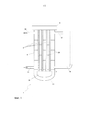
На фиг. 1 схематически показан теплообменник (1) в одном варианте осуществления изобретения.In FIG. 1 schematically shows a heat exchanger (1) in one embodiment of the invention.
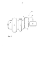
На фиг. 2 схематически показана реакторная система (101) в одном варианте осуществления изобретения.In FIG. 2 schematically shows a reactor system (101) in one embodiment of the invention.
Предлагаемый в изобретении теплообменник 1 показан на фиг. 1. Наружная оболочка теплообменника 1 образована кожухом 5 теплообменника, который вверху закрыт крышкой 9 теплообменника, а внизу днищем 11 теплообменника. Внутри теплообменника 1 расположены вертикально ориентированные трубки 3 теплообменника, которые внизу завершаются трубной решеткой 31 теплообменника. В одном варианте осуществления изобретения, в соответствии с которым теплообменник (1) эксплуатируют в качестве охладителя, трубки 3 теплообменника по меньшей мере частично заполнены водой, которую вводят через непоказанный на фиг. 1 соединительный патрубок. В одном варианте конструктивного исполнения между трубками 3 теплообменника, соответственно между трубками 3 теплообменника и кожухом 5 теплообменника размещены отражательные перегородки 25 таким образом, чтобы теплоноситель 7 омывал трубки 3 теплообменника в виде меандрирующего потока.The
Жидкий теплоноситель 7 подают в нижнюю половину кожуха 5 теплообменника по присоединенному к нему питающему трубопроводу 13. Место подачи теплоносителя 7 предпочтительно находится примерно на уровне трубной решетки 31 теплообменника. Теплоноситель 7 перемещается между трубками 3 теплообменника преимущественно поперек их ориентации, то есть в основном горизонтально, причем направление потока теплоносителя 7 определяется соответствующими отражательными перегородками 25. Охлажденный теплоноситель 7 выводят из теплообменника 1 по присоединенному к кожуху 5 теплообменника отводящему трубопроводу 15. Отводящий трубопровод 15 в частности, расположен немного ниже крышки 9. Как показано на фиг. 1, патрубок аварийной нагрузки 17 также расположен в верхней части кожуха 5 немного ниже крышки 9 теплообменника. Диаметр патрубка аварийной нагрузки 17 обычно составляет от 100 до 800 мм. Предлагаемое в изобретении устройство безопасности 19, напротив, расположено в нижней части кожуха 5 теплообменника, в частности, в нижней трети, предпочтительно в нижней четверти, прежде всего в нижней пятой части кожуха 5 теплообменника. Устройство безопасности 19 прежде всего служит для аварийного устранения давления и представляет собой стояк.The
На фиг. 2 показана реакторная система 101, включающая реактор 27, который предпочтительно является кожухотрубным реактором, предназначенным для осуществления экзотермических или эндотермических реакций. В кожухотрубном реакторе между двумя трубными решетками расположен пучок вертикально размещенных контактных трубок. При этом в зависимости от назначения реактора контактные трубки могут быть заполнены образующим неподвижный слой сыпучим катализатором. Контактные трубки омывает жидкий теплоноситель 7, который поглощает и отводит образующееся при экзотермической реакции тепло или, в случае эндотермической реакции, подводит необходимое тепло. Постоянство условий реакции обеспечивают благодаря тому, что при заданной температуре посредством насоса с целью термостатирования осуществлят циркуляцию теплоносителя 7.In FIG. 2 shows a
Место подачи теплоносителя 7 в реактор 27 предпочтительно находится вблизи нижней трубной решетки, а место выведения вблизи верхней трубной решетки.The place of supply of
Через реактор 27 пропускают теплоноситель 7, циркуляция по меньшей мере части которого осуществляется посредством насоса 29. Насос 29, а также соответствующие питающие и отводящие линии насоса 29 предпочтительно подвергают сопутствующему обогреву, что позволяет исключить непреднамеренное остывание теплоносителя 7 и обусловленное этим снижение его вязкости. В идеальном случае насос 29 размещен непосредственно на корпусе реактора. Как показано на фиг. 2, предлагаемый в изобретении теплообменник 1 преимущественно расположен напротив насоса 29. Насос 29 предпочтительно находится на относительно небольшом расстоянии от реактора 27, составляющем от 10 до 250 см. Из верхней части теплообменника 1, как показано также на фиг. 1, выведен патрубок снятия аварийной нагрузки 17. Напротив этого патрубка в нижней части теплообменника 1 расположено устройство безопасности 19, наличие которого является важным отличительным признаком настоящего изобретения.The
В случае разрыва трубок 3, при котором охлаждающая среда, главным образом вода и водяной пар, проникает из трубок 3 теплообменника в теплоноситель 7, попадающая в теплоноситель вода чрезвычайно быстро испаряется, что сопровождается внезапным повышением давления в теплообменнике 1. Благодаря наличию устройства безопасности 19 возникающее в нижней части теплообменника 1 давление может быть относительно быстро устранено посредством данного устройства. Это происходит вследствие выдавливания находящегося в устройстве безопасности 19 столба теплоносителя 7 вверх. В верхней части столба теплоносителя 7 как правило находится зона его повышенной вязкости, включающая почти твердые высоковязкие компоненты. Эти пробкоподобные компоненты в основном улавливают в сепараторе 23, в частности, промежуточном сепараторе, а, следовательно, их присутствие в последующей системе исключается. Затем смесь теплоносителя 7 с водой, а также водяным паром поступает по трубопроводу 33 в последовательно присоединенное улавливающее устройство 21. Устройство безопасности 19, а также трубопровод 33 и улавливающее устройство 21 подвергают сопутствующему обогреву, что позволяет предотвращать повышение вязкости, соответственно застывание теплоносителя 7.In the event of a
В улавливающем устройстве 21 жидкий теплоноситель 7 может быть отделен от воды/смеси воды с водяным паром. Теплоноситель можно отделять, в частности, посредством устройства для отделения жидкого теплоносителя 7 от газообразной фазы. Теплоноситель 7 можно отделять посредством центробежного сепаратора или благодаря простому гравитационному осаждению. Затем по непоказанному на фиг. 2 трубопроводу теплоноситель 7 можно возвращать в теплообменник 1, или, соответственно, реактор 27.In the
Claims (31)
Applications Claiming Priority (5)
| Application Number | Priority Date | Filing Date | Title |
|---|---|---|---|
| US201461954669P | 2014-03-18 | 2014-03-18 | |
| US61/954,669 | 2014-03-18 | ||
| DE102014103691.3A DE102014103691A1 (en) | 2014-03-18 | 2014-03-18 | Heat exchanger, reactor assembly comprising this heat exchanger and method for controlling the temperature of a reactor |
| DE102014103691.3 | 2014-03-18 | ||
| PCT/EP2015/054962 WO2015140009A2 (en) | 2014-03-18 | 2015-03-10 | Heat exchanger, reactor arrangement comprising said heat exchanger, and method for temperature control of a reactor |
Publications (3)
| Publication Number | Publication Date |
|---|---|
| RU2016140695A RU2016140695A (en) | 2018-04-18 |
| RU2016140695A3 RU2016140695A3 (en) | 2018-10-24 |
| RU2676167C2 true RU2676167C2 (en) | 2018-12-26 |
Family
ID=54053408
Family Applications (1)
| Application Number | Title | Priority Date | Filing Date |
|---|---|---|---|
| RU2016140695A RU2676167C2 (en) | 2014-03-18 | 2015-03-10 | Heat exchanger, including heat exchanger reactor system and method for thermostating reactor |
Country Status (12)
| Country | Link |
|---|---|
| US (1) | US9797657B2 (en) |
| EP (1) | EP3120099B1 (en) |
| JP (1) | JP6429895B2 (en) |
| KR (1) | KR102364341B1 (en) |
| CN (1) | CN106104188B (en) |
| BR (1) | BR112016021210B1 (en) |
| DE (1) | DE102014103691A1 (en) |
| MY (1) | MY182526A (en) |
| RU (1) | RU2676167C2 (en) |
| SG (1) | SG11201607209UA (en) |
| TW (1) | TWI664387B (en) |
| WO (1) | WO2015140009A2 (en) |
Families Citing this family (5)
| Publication number | Priority date | Publication date | Assignee | Title |
|---|---|---|---|---|
| DE102014114193A1 (en) | 2014-09-30 | 2015-08-13 | Basf Se | Process and plant for the recovery of acrylic acid |
| US20170356701A1 (en) * | 2016-06-13 | 2017-12-14 | Chevron U.S.A. Inc. | Apparatus, systems and methods for protection against high pressure gas intrusion in shell and tube heat exchangers |
| HRP20220027T1 (en) | 2017-10-27 | 2022-04-01 | Stamicarbon B.V. | High pressure carbamate condenser |
| EP3534100A1 (en) * | 2018-02-28 | 2019-09-04 | Valeo Autosystemy SP. Z.O.O. | A heat exchanger |
| EP4355473A1 (en) | 2021-06-16 | 2024-04-24 | Basf Se | Process for shutting-down and heating up a tubular reactor for a catalytic gas phase reaction |
Citations (4)
| Publication number | Priority date | Publication date | Assignee | Title |
|---|---|---|---|---|
| DE2207166A1 (en) * | 1972-02-16 | 1973-09-20 | Deggendorfer Werft Eisenbau | REFRIGERATION UNIT FOR REACTION APPARATUS FOR PERFORMING EXOTHERMAL CHEMICAL REACTIONS |
| DE102006034811A1 (en) * | 2006-07-27 | 2008-01-31 | Man Dwe Gmbh | Process for changing the temperature of a tube bundle reactor |
| RU2481887C2 (en) * | 2008-01-25 | 2013-05-20 | Басф Се | Reactor for high-pressure reactions, method of its starting and method of treatment |
| RU134687U1 (en) * | 2013-04-08 | 2013-11-20 | Федеральное государственное бюджетное образовательное учреждение высшего профессионального образования "Санкт-Петербургский государственный морской технический университет" | PASSIVE HEAT REMOVAL SYSTEM OF REACTOR INSTALLATION |
Family Cites Families (11)
| Publication number | Priority date | Publication date | Assignee | Title |
|---|---|---|---|---|
| DE898917C (en) * | 1942-09-20 | 1953-12-07 | Aenne Maria Luise Moos | Brine cooler closed on all sides |
| DE1057623B (en) * | 1955-02-08 | 1959-05-21 | Foster Wheeler Ltd | Heat exchanger used to exchange heat between a liquid and another medium |
| US4511432A (en) * | 1982-09-07 | 1985-04-16 | Sephton Hugo H | Feed distribution method for vertical tube evaporation |
| ZA200004211B (en) * | 1999-08-31 | 2001-02-14 | Nippon Catalytic Chem Ind | Method for catalytic gas phase oxidation. |
| DE102004041777A1 (en) | 2004-08-28 | 2006-03-02 | Bayer Materialscience Ag | Process and apparatus for the production of phosgene |
| WO2007048603A2 (en) * | 2005-10-26 | 2007-05-03 | Behr Gmbh & Co. Kg | Heat exchanger, method for the production of a heat exchanger |
| DE102008048405B3 (en) * | 2008-09-23 | 2010-04-22 | Alstom Technology Ltd. | Tube bundle heat exchanger for the regulation of a wide power range |
| CN201444004U (en) * | 2009-06-22 | 2010-04-28 | 大连优力特换热设备制造有限公司 | Detachable plate heat exchanger |
| JP2012149871A (en) * | 2010-12-28 | 2012-08-09 | Sumitomo Chemical Co Ltd | Multipipe heat exchange structure |
| CN102455139B (en) * | 2011-10-18 | 2014-04-16 | 张周卫 | Double-strand-flow low-temperature spiral winding pipe type heat exchanger with vacuum heat insulation function |
| CN203349689U (en) * | 2013-05-16 | 2013-12-18 | 江苏昊隆换热器有限公司 | Novel plate heat exchanger |
-
2014
- 2014-03-18 DE DE102014103691.3A patent/DE102014103691A1/en not_active Withdrawn
-
2015
- 2015-03-10 BR BR112016021210-0A patent/BR112016021210B1/en active IP Right Grant
- 2015-03-10 RU RU2016140695A patent/RU2676167C2/en active
- 2015-03-10 MY MYPI2016001659A patent/MY182526A/en unknown
- 2015-03-10 WO PCT/EP2015/054962 patent/WO2015140009A2/en active Application Filing
- 2015-03-10 SG SG11201607209UA patent/SG11201607209UA/en unknown
- 2015-03-10 JP JP2016558126A patent/JP6429895B2/en active Active
- 2015-03-10 EP EP15710466.2A patent/EP3120099B1/en active Active
- 2015-03-10 CN CN201580014566.2A patent/CN106104188B/en active Active
- 2015-03-10 KR KR1020167028745A patent/KR102364341B1/en active IP Right Grant
- 2015-03-18 TW TW104108662A patent/TWI664387B/en active
- 2015-03-18 US US14/661,408 patent/US9797657B2/en active Active
Patent Citations (4)
| Publication number | Priority date | Publication date | Assignee | Title |
|---|---|---|---|---|
| DE2207166A1 (en) * | 1972-02-16 | 1973-09-20 | Deggendorfer Werft Eisenbau | REFRIGERATION UNIT FOR REACTION APPARATUS FOR PERFORMING EXOTHERMAL CHEMICAL REACTIONS |
| DE102006034811A1 (en) * | 2006-07-27 | 2008-01-31 | Man Dwe Gmbh | Process for changing the temperature of a tube bundle reactor |
| RU2481887C2 (en) * | 2008-01-25 | 2013-05-20 | Басф Се | Reactor for high-pressure reactions, method of its starting and method of treatment |
| RU134687U1 (en) * | 2013-04-08 | 2013-11-20 | Федеральное государственное бюджетное образовательное учреждение высшего профессионального образования "Санкт-Петербургский государственный морской технический университет" | PASSIVE HEAT REMOVAL SYSTEM OF REACTOR INSTALLATION |
Also Published As
| Publication number | Publication date |
|---|---|
| KR20160133544A (en) | 2016-11-22 |
| WO2015140009A3 (en) | 2016-03-10 |
| WO2015140009A2 (en) | 2015-09-24 |
| US9797657B2 (en) | 2017-10-24 |
| JP2017510783A (en) | 2017-04-13 |
| RU2016140695A (en) | 2018-04-18 |
| EP3120099B1 (en) | 2019-06-12 |
| TW201544784A (en) | 2015-12-01 |
| SG11201607209UA (en) | 2016-10-28 |
| EP3120099A2 (en) | 2017-01-25 |
| RU2016140695A3 (en) | 2018-10-24 |
| US20150267967A1 (en) | 2015-09-24 |
| DE102014103691A1 (en) | 2015-09-24 |
| MY182526A (en) | 2021-01-25 |
| CN106104188B (en) | 2018-10-09 |
| KR102364341B1 (en) | 2022-02-17 |
| TWI664387B (en) | 2019-07-01 |
| BR112016021210B1 (en) | 2020-12-29 |
| JP6429895B2 (en) | 2018-11-28 |
| CN106104188A (en) | 2016-11-09 |
Similar Documents
| Publication | Publication Date | Title |
|---|---|---|
| RU2676167C2 (en) | Heat exchanger, including heat exchanger reactor system and method for thermostating reactor | |
| KR20170105004A (en) | System for passively removing heat from inside a containment shell | |
| GB1051135A (en) | ||
| NO132972B (en) | ||
| RU153270U1 (en) | NUCLEAR POWER PLANT | |
| JP6689335B2 (en) | Reactor system and its use | |
| RU2742730C1 (en) | Steam-generating plant of double-circuit nuclear reactor with blowdown and drainage system | |
| US20230017037A1 (en) | Nuclear reactor of integral type | |
| JP2009270183A (en) | Cooling system for furnace body of blast furnace | |
| RU2231144C2 (en) | Nuclear reactor emergency cooling device | |
| JP6072919B2 (en) | Reactor cooling system | |
| EP3631293A1 (en) | Vapour and liquid drum for a shell-and-tube heat exchanger | |
| RU2378571C1 (en) | Heat exchanger vertical | |
| CN103165200A (en) | Decay heat removal system of reactor | |
| CN115312219A (en) | Passive residual heat removal system of marine liquid metal reactor | |
| JP5801358B2 (en) | Reactor containment cooling system | |
| KR20140145772A (en) | Central fresh water cooling system for ship | |
| RU2635133C2 (en) | Plate for absorber | |
| EA030510B1 (en) | Nuclear facility | |
| JP2019120444A (en) | Cooling device | |
| CN104217773A (en) | Nuclear power plant steel safe containment vessel heat-conductive device | |
| JPS63159790A (en) | Nuclear reactor container | |
| JP2015183952A (en) | Heat transfer device |