RU2676103C2 - Dual screen system for connection with screening machine (versions) - Google Patents
Dual screen system for connection with screening machine (versions) Download PDFInfo
- Publication number
- RU2676103C2 RU2676103C2 RU2016111109A RU2016111109A RU2676103C2 RU 2676103 C2 RU2676103 C2 RU 2676103C2 RU 2016111109 A RU2016111109 A RU 2016111109A RU 2016111109 A RU2016111109 A RU 2016111109A RU 2676103 C2 RU2676103 C2 RU 2676103C2
- Authority
- RU
- Russia
- Prior art keywords
- sieve
- screen
- support
- frame
- double
- Prior art date
Links
Images

Classifications
-
- B—PERFORMING OPERATIONS; TRANSPORTING
- B07—SEPARATING SOLIDS FROM SOLIDS; SORTING
- B07B—SEPARATING SOLIDS FROM SOLIDS BY SIEVING, SCREENING, SIFTING OR BY USING GAS CURRENTS; SEPARATING BY OTHER DRY METHODS APPLICABLE TO BULK MATERIAL, e.g. LOOSE ARTICLES FIT TO BE HANDLED LIKE BULK MATERIAL
- B07B1/00—Sieving, screening, sifting, or sorting solid materials using networks, gratings, grids, or the like
- B07B1/46—Constructional details of screens in general; Cleaning or heating of screens
- B07B1/48—Stretching devices for screens
-
- B—PERFORMING OPERATIONS; TRANSPORTING
- B07—SEPARATING SOLIDS FROM SOLIDS; SORTING
- B07B—SEPARATING SOLIDS FROM SOLIDS BY SIEVING, SCREENING, SIFTING OR BY USING GAS CURRENTS; SEPARATING BY OTHER DRY METHODS APPLICABLE TO BULK MATERIAL, e.g. LOOSE ARTICLES FIT TO BE HANDLED LIKE BULK MATERIAL
- B07B1/00—Sieving, screening, sifting, or sorting solid materials using networks, gratings, grids, or the like
- B07B1/46—Constructional details of screens in general; Cleaning or heating of screens
- B07B1/4609—Constructional details of screens in general; Cleaning or heating of screens constructional details of screening surfaces or meshes
- B07B1/4663—Multi-layer screening surfaces
-
- B—PERFORMING OPERATIONS; TRANSPORTING
- B07—SEPARATING SOLIDS FROM SOLIDS; SORTING
- B07B—SEPARATING SOLIDS FROM SOLIDS BY SIEVING, SCREENING, SIFTING OR BY USING GAS CURRENTS; SEPARATING BY OTHER DRY METHODS APPLICABLE TO BULK MATERIAL, e.g. LOOSE ARTICLES FIT TO BE HANDLED LIKE BULK MATERIAL
- B07B2201/00—Details applicable to machines for screening using sieves or gratings
- B07B2201/02—Fastening means for fastening screens to their frames which do not stretch or sag the screening surfaces
-
- B—PERFORMING OPERATIONS; TRANSPORTING
- B07—SEPARATING SOLIDS FROM SOLIDS; SORTING
- B07B—SEPARATING SOLIDS FROM SOLIDS BY SIEVING, SCREENING, SIFTING OR BY USING GAS CURRENTS; SEPARATING BY OTHER DRY METHODS APPLICABLE TO BULK MATERIAL, e.g. LOOSE ARTICLES FIT TO BE HANDLED LIKE BULK MATERIAL
- B07B2201/00—Details applicable to machines for screening using sieves or gratings
- B07B2201/04—Multiple deck screening devices comprising one or more superimposed screens
Landscapes
- Combined Means For Separation Of Solids (AREA)
- Separation Of Solids By Using Liquids Or Pneumatic Power (AREA)
Abstract
Description
Область техникиTechnical field
Изобретение относится к усовершенствованной вибрационной просеивающей системе для разделения твердых веществ и жидкостей и, в частности, к отделению выбуренной породы от промывочной жидкости. В различных вариантах описаны двухситные системы для прикрепления с целью модернизации к существующим однодековым вибрационным грохотам.The invention relates to an improved vibratory screening system for the separation of solids and liquids, and in particular, to the separation of cuttings from drilling fluid. In various embodiments, dual-screen systems for attaching for modernization to existing single-deck vibrating screens are described.
Уровень техникиState of the art
Просеивающие машины в течение долгих лет используют в различных отраслях промышленности, включая горнодобывающую и нефтяную, для осуществления разделения твердых веществ и жидкостей. В этих отраслях промышленности при выполнении бурения и добычи минеральных полезных ископаемых часто возникают суспензии из твердых веществ и жидкостей, которые должны быть отделены друг от друга. Как хорошо известно, просеивающая машина, как правило, включает ложе сита, над которым подают раствор, содержащий жидкости и твердые вещества, и затем подвергают воздействию различных разделяющих сил, включающих силу тяжести и встряхивание. В каждом просеивающем разделительном устройстве будут применяться различные типы и размеры сит, чтобы сделать возможным разделение различных жидкостей/твердых веществ. В дополнение к этому, также используют вакуумные системы для улучшения разделения в просеивающих системах, включая использование пульсирующего вакуумметрического давления, как описано в находящихся одновременно на рассмотрении заявках на патент и выданных патентах автора настоящего изобретения.Sieving machines have been used for many years in various industries, including mining and petroleum, to separate solids and liquids. In these industries, when drilling and extracting minerals, suspensions of solids and liquids often arise, which must be separated from each other. As is well known, a sieving machine typically includes a bed of sieves, over which a solution containing liquids and solids is fed, and then subjected to various separating forces, including gravity and shaking. Each sieve separator will use different types and sizes of sieves to make it possible to separate different liquids / solids. In addition, vacuum systems are also used to improve separation in sieving systems, including the use of pulsating vacuum pressure, as described in the patent applications pending and the patents granted by the author of the present invention.
В зависимости от отрасли промышленности, просеиваемых растворов из жидкости/твердого вещества и коммерческих целей просеивающих систем, существуют различные конструкции просеивающих машин. Если рассматривать различные машины, каждая машина наделена определенными функциями для использования в конкретной отрасли промышленности или с конкретными растворами из твердого вещества/жидкости. Нюансы каждого основного типа раствора из твердого вещества/жидкости и каждой машины, в общем, подразумевают, что один тип машины не будет работоспособным или эффективным в другой отрасли промышленности, так как во многих случаях при работе с конкретными типами материалов или растворов имеют место специфичные проблемы. Например, многие конструкции просеивающих машин разработаны для оптимизации извлечения твердых материалов из суспензии, однако этот формат ведет к игнорированию качества извлеченной жидкости. По сути, в общем, не рассматривалось то, как осуществлять разделение твердых веществ и жидкостей при одновременном сохранении или повышении качества извлекаемой жидкости.Depending on the industry, the sieved solutions of the liquid / solid and the commercial purposes of the sieving systems, there are various designs of sieving machines. If we consider different machines, each machine is endowed with certain functions for use in a particular industry or with specific solutions of solid / liquid. The nuances of each basic type of solution from a solid / liquid and each machine, in general, imply that one type of machine will not be workable or effective in another industry, since in many cases there are specific problems when working with specific types of materials or solutions . For example, many sieving machine designs are designed to optimize the recovery of solid materials from a slurry, but this format ignores the quality of the recovered fluid. In fact, in general, it was not considered how to separate solids and liquids while maintaining or improving the quality of the extracted liquid.
В конкретном случае отделения промывочной жидкости от выбуренной породы на буровой площадке, заявителем в последние годы эффективным образом были введены в эксплуатацию вакуумные системы для отделения промывочной жидкости от выбуренной породы. Как описано в находящихся одновременно на рассмотрении и включенных сюда их упоминанием заявках автора настоящего изобретения (РСТ/СА2009/001555, зарегистрированной 29 октября 2009, РСТ/СА2010/00501, зарегистрированной 31 марта 2010 и РСТ/СА2011/000542, зарегистрированной 11 мая 2011), использование воздействия силы вакуума на систему грохота, при корректном ее приложении, может оказаться в высшей степени эффективным при восстановлении промывочной жидкости, удерживаемой в выбуренной породе, с целью увеличения количества извлеченной промывочной жидкости, при одновременном снижении до минимума повреждения выбуренной породы, что может привести к загрязнению промывочной жидкости мелкими твердыми материалами, которые могут проходить через сита, для повышения качества извлеченной промывочной жидкости.In the specific case of separating the washing liquid from the cuttings at the drilling site, in recent years the applicant has effectively put into operation vacuum systems for separating the washing liquid from the cuttings. As described in the pending and simultaneously incorporated by reference applications of the author of the present invention (PCT / CA2009 / 001555, registered on October 29, 2009, PCT / CA2010 / 00501, registered on March 31, 2010 and PCT / CA2011 / 000542, registered on May 11, 2011) , the use of the influence of vacuum force on the screening system, if applied correctly, can be extremely effective in restoring the flushing fluid held in the cuttings, in order to increase the amount of flushing fluid recovered, when while minimizing damage to the cuttings to a minimum, which can lead to contamination of the flushing fluid with small solid materials that can pass through the sieves to improve the quality of the extracted flushing fluid.
Кроме того, эффективность систем грохотов важна с точки зрения снижения до минимума затрат на управление твердыми веществами в скважине. Например, в большинстве буровых агрегатов для одновременной обработки выбуренной породы, поступающей от агрегата, установлено несколько систем грохотов. В качестве общепринятой практики, как правило, выделяют два или более грохотов (часто 3 или более и, возможно, до 9 грохотов) для бурового агрегата, расположенного рядом с противовыбросовым устройством (ВОР, BlowOut Preventer). По мере того, как промывочная жидкость и выбуренная порода выходят из устья скважины, они транспортируются к грохотам, по каналам к питающей емкости каждого из грохотов. Транспортируемые выбуренная порода и промывочная жидкость обычно разделяются на отдельные потоки в устье скважины, чтобы к каждому грохоту подавалось относительно одинаковое количество породы/жидкости.In addition, the effectiveness of screening systems is important in terms of minimizing the cost of managing solid substances in the well. For example, in most drilling rigs, several screening systems are installed to simultaneously process cuttings coming from the aggregate. As a common practice, as a rule, two or more screens (often 3 or more and possibly up to 9 screens) are allocated for a drilling unit located next to a blowout preventer (BOP, BlowOut Preventer). As flushing fluid and cuttings come out of the wellhead, they are transported to screens, through channels to the supply tank of each of the screens. The drill cuttings and flushing fluid transported are usually separated into separate flows at the wellhead so that a relatively equal amount of rock / fluid is delivered to each screen.
Как можно понять, общее число грохотов, которые могут применяться на буровой площадке, будет значительно влиять на общие затраты программы по работе с твердыми веществами. То есть, затраты на работу с твердыми веществами можно уменьшить, если требуется меньшее число грохотов.As you can understand, the total number of screens that can be used at the drilling site will significantly affect the total costs of the program for working with solids. That is, the costs of handling solids can be reduced if fewer screens are required.
В дополнение к этому, в типичном сценарии системы грохотов могут быть установлены последовательно, при этом в расположенном выше по ходу технологического процесса грохоте может применяться крупноячеистое сито, а в расположенном ниже по ходу технологического процесса грохоте может применяться сито с более мелкой ячейкой. Понятно, что крупноячеистое сито будет позволять относительно более мелким частицам твердого вещества и промывочной жидкости проходить через него, а сито с более мелкой ячейкой будет позволять проходить через него промывочной жидкости, одновременно задерживая более мелкие частицы на верхней поверхности сита.In addition to this, in a typical scenario, the screening systems can be installed in series, while in the upstream screen, a coarse sieve can be used, and in the downstream screen, a sieve with a smaller cell can be used. It is understood that a coarse sieve will allow relatively smaller particles of solid and wash liquid to pass through it, and a sieve with a smaller cell will allow wash liquid to pass through it, while delaying smaller particles on the upper surface of the sieve.
В общем случае, должен поддерживаться баланс между размером ячеек сита и требуемой скоростью обработки. Например, чтобы сохранить эффективный расход в грохоте, обычно используется комбинация крупноячеистого и мелкоячеистого сит, в результате чего в конкретный период времени извлекаются достаточные объемы жидкости. То есть, если используется слишком мелкоячеистое сито, эффективность по времени, требуемому для обработки объема выбуренной породы и промывочной жидкости, становится неудовлетворительной, и/или может прекратиться разделение выбуренной породы и промывочной жидкости из-за засорения и/или забивания сита. При этом, если используется слишком крупноячеистое сито, снижается эффективность разделения жидкости/породы, так как из-за твердых загрязнений снижается качество извлеченной промывочной жидкости.In general, a balance should be maintained between the size of the sieve cells and the required processing speed. For example, in order to maintain an effective flow rate in a screen, a combination of coarse and fine meshed screens is usually used, as a result of which sufficient volumes of liquid are recovered during a specific period of time. That is, if a too fine mesh sieve is used, the time efficiency required to process the volume of cuttings and flushing fluid becomes unsatisfactory, and / or the separation of the cuttings and flushing fluid may stop due to clogging and / or clogging of the screen. In this case, if a coarse-mesh sieve is used, the liquid / rock separation efficiency is reduced, since the quality of the extracted washing liquid decreases due to solid impurities.
В прошлом были разработаны различные сита и системы грохотов для повышения эффективности разделения, включая трехмерные конструкции сита и системы грохота. Например, в патенте США № 6,032,806 описано сито грохота в виде "пирамиды", которое имеет трехмерную геометрию для увеличения его площади поверхности. Были разработаны и другие системы грохотов, которые включают отдельные деки для отделения твердых веществ в разных положениях по вертикали внутри грохота. Однако эти последние системы остаются неэффективными в ряде аспектов. Например, двухдековые грохоты дороже изготавливать, так как для деки каждого уровня требуются отдельные дековые системы и системы крепления, например, зажимы, клинья или крюки. В дополнение к этому, эти системы часто значительно выше, чем обычный одноуровневый грохот.In the past, various sieves and screening systems have been developed to increase separation efficiency, including three-dimensional screen designs and screening systems. For example, US Pat. No. 6,032,806 describes a screening screen in the form of a "pyramid" that has three-dimensional geometry to increase its surface area. Other screening systems have been developed that include separate decks for separating solids in different vertical positions within the screen. However, these latter systems remain ineffective in a number of aspects. For example, two-deck screens are more expensive to produce, since each deck requires separate deck and fastening systems, such as clamps, wedges or hooks. In addition to this, these systems are often significantly higher than a conventional single-level screen.
Существует несколько различных систем крепления, которые обычно используются для фиксации системы сит в грохоте, а именно, в кассете грохота. Одна такая система крепления представляет собой систему на основе клиньев. Система на основе клиньев, как правило, содержит сжимающие клинья, которые расположены на боковых сторонах кассеты грохота, причем каждый клин вводят в направляющую, расположенную выше положения, где находится сито, чтобы зафиксировать сито на месте в кассете. Сжимающий клин, как правило, имеет ширину приблизительно 1 дюйм (25,4 мм) и длину приблизительно 12-18 дюймов (304,8–457,2 мм), и на одно сито, как правило, используется два клина.There are several different mounting systems that are commonly used to fix the sieve system in the screen, namely in the screen cassette. One such fastening system is a wedge-based system. The wedge-based system typically comprises compression wedges that are located on the sides of the screen cassette, each wedge being inserted into a guide located above the sieve to fix the sieve in place in the cassette. A compression wedge typically has a width of about 1 inch (25.4 mm) and a length of about 12-18 inches (304.8–457.2 mm), and two wedges are typically used per sieve.
Альтернативная система крепления представляет собой систему зажимания при помощи пластин, которая в общем содержит пластины или планки, расположенные на боковых сторонах кассеты грохота, которые сжимают вместе, используя воздушное или гидравлическое давление, чтобы зажать край сита между пластинами/планками. Пластины или планки имеют ширину, как правило, приблизительно от 1 до 1½ дюймов (от 25,4 до 38,1 мм). An alternative fastening system is a plate clamping system that generally comprises plates or strips located on the sides of the screen cartridge, which are compressed together using air or hydraulic pressure to grip the edge of the screen between the plates / strips. The plates or strips have a width of typically about 1 to 1 1/2 inches (25.4 to 38.1 mm).
Третий тип системы крепления представляет собой систему на основе крюков, которая тянет края сита к боковым сторонам кассеты грохота, чтобы создать натяжение в сите. Это обычно делают, используя тягу, которую можно прикрепить к боковой стороне сита при помощи крюка. К тяге прикладывают силу, которая тянет тягу через отверстие, находящееся в боковой стороне кассеты грохота, что тянет сито наружу, создавая в нем натяжение. Как правило, сила, приложенная к тяге, создается пружиной, однако в некоторых конструкциях пружина заменена узлом из болта и винта, который регулируют до получения заранее определенного момента затяжки, либо узлом воздушного или гидравлического плунжера. В случае системы крепления сит при помощи крюков, сито можно тянуть по плоской поверхности или по криволинейной поверхности, например, выпуклой поверхности. Сита грохота пирамидального вида часто прикрепляют к грохотам, используя крюки. Пример системы крепления сит при помощи крюков описан в патенте США № 6,179,128.A third type of attachment system is a hook-based system that pulls the edges of the sieve to the sides of the screen cassette to create tension in the sieve. This is usually done using a rod that can be attached to the side of the sieve with a hook. A force is applied to the draft, which pulls the draft through an opening located on the side of the screen cassette, which pulls the sieve outward, creating tension in it. Typically, the force exerted on the rod is generated by the spring, however, in some designs, the spring is replaced by a bolt and screw assembly, which is adjusted to a predetermined tightening torque, or by an air or hydraulic plunger assembly. In the case of a hook fastening system, the screen can be pulled along a flat surface or along a curved surface, such as a convex surface. Pyramidal-type screen sieves are often attached to screens using hooks. An example of a hook fastening system for sieves is described in US Pat. No. 6,179,128.
Проблемой, связанной с известными грохотами, является воздействие как больших, так небольших частиц на сито. То есть, частицы большего размера имеют тенденцию ударяться о сито с большей силой из-за кинетической энергии частицы. Мелкоячеистые сита, с более тонкой и менее прочной проволокой, могут приходить в негодность быстрее в результате ударения о них частиц большего размера. Таким образом, многослойная система сит с верхним ситом с более крупной ячейкой и нижним ситом с менее крупной ячейкой имеет преимущество, заключающееся в защите нижнего сита от частиц большего размера и потенциально могущих нанести повреждения, так как эти частицы будут перемещаться по верхнему ситу и не будут проходить через это сито для ударения о мелкоячеистое сито, расположенное ниже.A problem associated with known screens is the effect of both large and small particles on the sieve. That is, larger particles tend to hit the sieve with more force due to the kinetic energy of the particle. Fine-meshed sieves with a finer and less durable wire can deteriorate more quickly as a result of the impact of larger particles on them. Thus, the multilayer sieve system with a higher sieve with a larger mesh and a lower sieve with a smaller mesh has the advantage of protecting the lower sieve from larger particles and potentially causing damage, as these particles will move along the upper sieve and will not pass through this sieve to hit the fine mesh sieve below.
Другой проблемой является то, что важно обеспечить, чтобы поток выбуренной породы и промывочной жидкости по грохоту не влиял негативно на многослойную систему сит, таким образом, что это будет влиять на производительность сит/грохота. В частности, важно, чтобы зазор между нижним ситом и верхним ситом не засорялся, если поток промывочной жидкости/выбуренной породы через зазор увеличивается из-за объема материала в грохоте.Another problem is that it is important to ensure that the flow of cuttings and flushing fluid over the screen does not adversely affect the multilayer sieve system, so that this will affect the performance of the sieve / screen. In particular, it is important that the gap between the lower sieve and the upper sieve does not become clogged if the flow of flushing fluid / cuttings through the gap increases due to the volume of material in the screen.
В результате, остается потребность в системах, которые повышают эффективность систем грохотов, чтобы сделать возможным последовательное разделение твердых веществ с частицами более крупного размера и твердых веществ с частицами мелкого размера. В дополнение к этому, также существует потребность в системах, с использованием которых можно модернизировать существующие системы грохотов, включая существующие системы крепления системы грохота, чтобы эффективным образом превратить однодековые системы в двухдековые просеивающие системы. As a result, there remains a need for systems that increase the efficiency of screening systems to enable sequential separation of solids with larger particles and solids with smaller particles. In addition to this, there is also a need for systems that can be used to upgrade existing screening systems, including existing mounting systems for screening systems, in order to efficiently turn single deck systems into double deck screening systems.
Сущность изобретенияSUMMARY OF THE INVENTION
Согласно изобретению, предлагается двухситная система для соединения с вибрационным грохотом с целью модернизации.According to the invention, a dual-screen system for connecting to a vibrating screen for retrofitting is provided.
В одном варианте реализации настоящего изобретения двухситная система содержит узел верхнего сита, имеющий нежесткое соединение с узлом нижнего сита с созданием канала между узлами верхнего сита и нижнего сита, причем каждый узел сита имеет раму и сетку сита, прикрепленную к раме, узел верхнего сита имеет сетку с более крупной ячейкой, чем нижнее сито, и двухситная система приспособлена для нежесткого соединения с вибрационным грохотом.In one embodiment of the present invention, the two-sieve system comprises an upper sieve assembly having a non-rigid connection with the lower sieve assembly to create a channel between the upper sieve and lower sieve assemblies, each sieve assembly having a frame and a sieve mesh attached to the frame, the upper sieve assembly having a mesh with a larger cell than the lower sieve, and a two-sieve system is adapted for non-rigid connection with a vibrating screen.
В следующем варианте узел верхнего сита выполнен с возможностью отсоединения от узла нижнего сита. Рама верхнего сита может включать множество опор для прикрепления к множеству соответствующих опор на раме нижнего сита, и упомянутые множества опор на рамах верхнего и нижнего сит могут собираться воедино.In a further embodiment, the upper sieve assembly is adapted to disconnect from the lower sieve assembly. The upper sieve frame may include a plurality of supports for attaching to a plurality of corresponding supports on the lower sieve frame, and said plurality of supports on the upper and lower sieve frames may be assembled together.
В другом варианте двухситная система дополнительно содержит отдельный узел соединителя, находящийся между узлами верхнего и нижнего сит, для соединения рамы верхнего сита с рамой нижнего сита, причем узел соединителя создает канал. В одном варианте узел соединителя содержит раму, опорой которой служит множество опор, причем эта рама предназначена для нежесткого соединения с рамами верхнего и нижнего сит. Узел соединителя может дополнительно содержать первое множество штырей, выступающих сверху рамы, для вставки в отверстия снизу рамы верхнего сита; и второе множество штырей, выступающих снизу опор, для вставки в отверстия сверху рамы нижнего сита.In another embodiment, the two-sieve system further comprises a separate connector assembly located between the nodes of the upper and lower sieves for connecting the frame of the upper sieve to the frame of the lower sieve, the connector assembly creating a channel. In one embodiment, the connector assembly comprises a frame, the support of which is a plurality of supports, this frame being designed for non-rigid connection with the frames of the upper and lower screens. The connector assembly may further comprise a first plurality of pins protruding from the top of the frame for insertion into openings below the frame of the upper sieve; and a second plurality of pins protruding from below the supports for insertion into openings on top of the lower sieve frame.
В еще одном варианте узел соединителя содержит множество стержней, идущих параллельно рамам узлов верхнего и нижнего сит. Упомянутое множество стержней может иметь первое множество штырей, выступающих сверху стержней, для вставки в отверстия снизу рамы верхнего сита; и второе множество штырей, выступающих снизу стержней, для вставки в отверстия сверху рамы нижнего сита. В другом варианте, чтобы гарантировать, что узлы верхнего и нижнего сит не скользят, можно использовать резиновые прокладки и/или системы зажимания высокого давления.In yet another embodiment, the connector assembly comprises a plurality of rods extending parallel to the frames of the upper and lower sieve assemblies. Said plurality of rods may have a first plurality of pins protruding from above the rods for insertion into openings below the frame of the upper sieve; and a second plurality of pins protruding from below the rods for insertion into openings on top of the lower sieve frame. Alternatively, to ensure that the top and bottom screens do not slip, rubber gaskets and / or high pressure clamping systems can be used.
В одном варианте боковые края рамы верхнего сита смещены относительно боковых краев рамы нижнего сита. В следующем варианте рама верхнего сита включает выступ, проходящий по одному краю двухситной системы, для направления потока по краю двухситного узла.In one embodiment, the side edges of the upper sieve frame are offset from the side edges of the lower sieve frame. In a further embodiment, the upper sieve frame includes a protrusion extending along one edge of the dual-screen system to direct flow along the edge of the dual-screen unit.
В другом варианте рамы верхнего и/или нижнего сит выполнены в виде клина. Канал, созданный рамами в виде клина, может иметь, по существу, постоянную высоту.In another embodiment, the frames of the upper and / or lower screens are made in the form of a wedge. A channel created by wedge frames can have a substantially constant height.
В следующем варианте в вибрационном грохоте располагают множество двухситных систем, чтобы создать непрерывный путь протекания через каналы этого множества двухситных систем от конца, расположенного выше по ходу технологического процесса, до конца, расположенного ниже по ходу технологического процесса. Упомянутое множество двухситных систем может быть расположено в вибрационном грохоте ступенчатым образом, при этом край узлов верхнего сита, расположенный выше по ходу технологического процесса, смещен относительно края узлов нижнего сита, расположенного выше по ходу технологического процесса, для увеличения пространства пути протекания между соседними узлами нижнего сита.In a further embodiment, a plurality of double-screen systems are arranged in a vibrating screen to create a continuous path through the channels of this set of double-screen systems from the end located upstream of the process to the end located downstream of the process. The aforementioned set of double-sieve systems can be arranged in a vibrating screen in a stepwise manner, while the edge of the nodes of the upper sieve located upstream of the process is offset from the edge of the nodes of the lower sieve located upstream of the process to increase the space of the flow path between adjacent nodes of the lower sieves.
В одном варианте, в котором рамы верхнего и/или нижнего сит выполнены в виде клина, они могут быть расположены в вибрационном грохоте ступенчатым образом, чтобы создать непрерывный путь протекания через каналы. Непрерывный путь протекания может представлять собой каскадный путь протекания.In one embodiment, in which the frames of the upper and / or lower screens are made in the form of a wedge, they can be arranged in a vibrating screen in a stepwise manner to create a continuous path through the channels. The continuous flow path may be a cascade flow path.
В еще одном варианте сетка верхнего сита имеет размер 325 меш или менее, а сетка нижнего сита имеет размер больше 30 меш.In yet another embodiment, the upper sieve mesh has a size of 325 mesh or less, and the lower sieve mesh has a size greater than 30 mesh.
В следующем варианте канал имеет высоту 3 дюйма (76,2 мм) или менее и предпочтительно 2 дюйма (50,8 мм) или менее.In a further embodiment, the channel has a height of 3 inches (76.2 mm) or less, and preferably 2 inches (50.8 mm) or less.
В одном варианте двухситная система предназначена для соединения с целью модернизации с грохотом, имеющим уже существующее плоское ложе сита, в этой системе двухситные системы из упомянутого множества двухситных систем имеют такой размер по высоте, чтобы получить каскадный эффект между двухситными системами.In one embodiment, a two-sieve system is intended to be connected for modernization with a screen having an already existing flat bed of sieves, in this system two-sieve systems from the aforementioned set of two-sieve systems have such a height dimension to obtain a cascade effect between the two-sieve systems.
В другом варианте реализации настоящего изобретения двухситная система выполнена с возможностью фиксации на основании вибрационного грохота с использованием существующей системы крепления с зажиманием при помощи клиньев в основании грохота. Двухситная система может включать кронштейн крепления на каждой боковой стороне, кронштейны крепления предназначены для зажимания с использованием клиньев системы зажимания при помощи клиньев. Двухситная система может быть выполнена таких размеров, чтобы для ее фиксации на основании грохота можно было использовать существующие клинья системы крепления с зажиманием при помощи клиньев, без модификации этой системы. Ширина, по меньшей мере, одного из узлов верхнего или нижнего сит меньше на ширину кронштейнов крепления.In another embodiment of the present invention, a two-screen system is configured to be fixed based on a vibrating screen using an existing fastening system with clamping using wedges at the base of the screen. The dual-screen system may include a mounting bracket on each side, mounting brackets are designed to be clamped using wedges of the clamping system with wedges. The double-screen system can be made in such a size that, to fix it on the basis of the screen, it is possible to use the existing wedges of the fastening system with clamping using wedges, without modification of this system. The width of at least one of the nodes of the upper or lower sieves is less than the width of the mounting brackets.
В одном варианте реализации настоящего изобретения двухситная система выполнена с возможностью фиксации на основании вибрационного грохота с использованием существующей системы крепления с зажиманием при помощи гидравлического или воздушного давления, расположенной на основании грохота.In one embodiment of the present invention, a two-screen system is configured to be fixed based on a vibrating screen using an existing clamping system using hydraulic or air pressure located at the base of the screen.
В другом варианте двухситная система выполнена с возможностью фиксации на основании вибрационного грохота с использованием существующей системы крепления при помощи крюков, расположенной на основании грохота. Система крепления при помощи крюков может быть модифицирована с включением верхнего и нижнего крюков, и каждый из узлов верхнего и нижнего сит включает соответствующий крюк для прикрепления к верхнему и нижнему крюкам, соответственно. В узлах верхнего и нижнего сит может быть создано натяжение с использованием одного натягивающего устройства крепления.In another embodiment, the two-screen system is made with the possibility of fixing on the basis of a vibrating screen using the existing fastening system using hooks located on the basis of the screen. The hook fastening system can be modified to include upper and lower hooks, and each of the top and bottom sieve assemblies includes a corresponding hook for attaching to the upper and lower hooks, respectively. In the nodes of the upper and lower sieves, tension can be created using a single tensioning fastener.
В следующем варианте верхнее и нижнее сита представляют собой пирамидальные сита.In a further embodiment, the upper and lower sieves are pyramidal sieves.
Согласно другому аспекту, изобретением предлагается двухситная система для соединения с целью модернизации с грохотом, обеспечивающим опору для, по меньшей мере, двух ступенчатых сит в виде соответствующих опорных кронштейнов в кассете грохота, причем двухситная система содержит: опору нижнего сита, имеющую размеры, подходящие для встраивания между опорными кронштейнами и ниже их, причем опора нижнего сита служит опорой первому нижнему ситу; опору верхнего сита, нежестко соединенную с опорой нижнего сита, причем опора верхнего сита имеет размеры, подходящие для встраивания выше опорных кронштейнов, и опора верхнего сита служит опорой первому верхнему ситу; причем опора нижнего сита и опора верхнего сита создают пару опор сдвоенных сит, и двухситная система включает пару опор сдвоенных сит для каждой ступени грохота.According to another aspect, the invention provides a two-screen system for connecting for modernization with a screen, providing support for at least two step screens in the form of corresponding support brackets in the screen cassette, the two-screen system comprising: a lower screen support having dimensions suitable for embedding between the supporting brackets and below them, and the support of the lower sieve supports the first lower sieve; the support of the upper sieve, non-rigidly connected to the support of the lower sieve, moreover, the support of the upper sieve has dimensions suitable for installation above the support brackets, and the support of the upper sieve supports the first upper sieve; moreover, the lower sieve support and the upper sieve support create a pair of double sieve supports, and the two-sieve system includes a pair of double sieve supports for each stage of the screen.
В одном варианте соседние пары опор сдвоенных сит скреплены вместе.In one embodiment, adjacent pairs of double sieve supports are fastened together.
В другом варианте поверхности сит прикреплены к опоре нижнего сита и опоре верхнего сита для каждой пары опор сдвоенных сит.In another embodiment, the surface of the sieves attached to the support of the lower sieve and the support of the upper sieve for each pair of supports of double sieves.
В одном варианте каждая поверхность сита включает выступ, расположенный ниже по ходу технологического процесса, который имеет такие размеры, чтобы он перекрывался с расположенным выше по ходу технологического процесса краем соседнего сита, расположенного ниже по ходу технологического процесса.In one embodiment, each surface of the sieve includes a protrusion located downstream of the process, which is dimensioned so that it overlaps with the edge of the adjacent sieve located upstream of the adjacent process, located downstream of the process.
В одном варианте крупноячеистое сито прикреплено к каждой опоре верхнего сита, и мелкоячеистое сито прикреплено к каждой опоре нижнего сита.In one embodiment, a coarse mesh sieve is attached to each support of the upper sieve, and a fine mesh sieve is attached to each support of the lower sieve.
Краткое описание чертежейBrief Description of the Drawings
Изобретение описано со ссылкой на сопровождающие чертежи, из которых:The invention is described with reference to the accompanying drawings, of which:
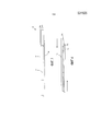
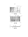
на Фиг.1 приведен вид спереди двухситной системы согласно одному варианту реализации настоящего изобретения;1 is a front view of a dual-screen system according to one embodiment of the present invention;
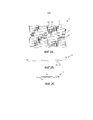
на Фиг.2А приведен вид сверху узла верхнего сита, имеющего соединительные элементы с канавками, согласно одному варианту реализации настоящего изобретения;FIG. 2A is a plan view of an overhead assembly having connecting elements with grooves, according to one embodiment of the present invention;
на Фиг.2В приведен вид спереди узла верхнего сита, имеющего соединительные элементы с канавками, согласно первому варианту реализации настоящего изобретения;FIG. 2B is a front view of a top screen assembly having connecting elements with grooves according to a first embodiment of the present invention;
на Фиг.2С приведен вид сбоку узла верхнего сита, имеющего соединительные элементы с канавками, согласно первому варианту реализации настоящего изобретения;Fig. 2C is a side view of a top sieve assembly having connecting elements with grooves according to a first embodiment of the present invention;
на Фиг.3А приведен вид сверху узла нижнего сита, имеющего соединительные элементы, согласно первому варианту реализации настоящего изобретения;3A is a plan view of a lower sieve assembly having connecting members according to a first embodiment of the present invention;
на Фиг.3В приведен вид спереди узла нижнего сита, имеющего соединительные элементы, согласно первому варианту реализации настоящего изобретения;3B is a front view of a lower sieve assembly having connecting members according to a first embodiment of the present invention;
на Фиг.3С приведен вид сбоку узла нижнего сита, имеющего соединительные элементы, согласно первому варианту реализации настоящего изобретения;3C is a side view of a lower sieve assembly having connecting members according to a first embodiment of the present invention;
на Фиг.4 приведен вид сбоку узлов верхнего и нижнего сит, соединяемых за счет скольжения соединительных элементов этих узлов друг относительно друга, согласно первому варианту реализации настоящего изобретения;figure 4 shows a side view of the nodes of the upper and lower screens, connected by sliding the connecting elements of these nodes relative to each other, according to the first embodiment of the present invention;
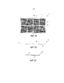
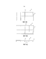
на Фиг.5А приведен вид спереди двухситной системы, имеющей узел верхнего сита, узел нижнего сита и центральный разделитель, согласно второму варианту реализации настоящего изобретения;Fig. 5A is a front view of a two-sieve system having an upper sieve assembly, a lower sieve assembly, and a central spacer according to a second embodiment of the present invention;
на Фиг.5В приведен вид спереди двухситной системы, имеющей узел верхнего сита с укороченными краями, узел нижнего сита и центральный разделитель, согласно третьему варианту реализации настоящего изобретения. Укороченные края позволяют работать механизму зажимания при помощи клиньев или гидравлического/воздушного давления, одновременно позволяя увеличить зазор за верхним ситом, который может возникнуть, если верхнее сито имеет поверхность зажимания, расположенную на той же высоте, что и верх деки сита;Fig. 5B is a front view of a two-screen system having a top screen assembly with shortened edges, a bottom screen assembly and a central separator according to a third embodiment of the present invention. The shortened edges allow the clamping mechanism to work with wedges or hydraulic / air pressure, while also allowing an increase in the clearance behind the top screen, which can occur if the top screen has a clamping surface located at the same height as the top of the screen deck;
на Фиг.5С приведен вид спереди двухситной системы, имеющей узел верхнего сита, узел нижнего сита и стержневую соединительную систему, согласно четвертому варианту реализации настоящего изобретения;Fig. 5C is a front view of a two-sieve system having an upper sieve assembly, a lower sieve assembly, and a rod joint system according to a fourth embodiment of the present invention;
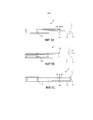
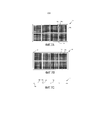
на Фиг.6А приведен вид сверху узла верхнего сита, согласно одному варианту реализации настоящего изобретения;Fig. 6A is a plan view of a top sieve assembly according to one embodiment of the present invention;
на Фиг.6В приведен вид снизу узла верхнего сита, согласно одному варианту реализации настоящего изобретения;FIG. 6B is a bottom view of a top sieve assembly according to one embodiment of the present invention;
на Фиг.6С приведен вид спереди узла верхнего сита, согласно одному варианту реализации настоящего изобретения;Fig. 6C is a front view of a top sieve assembly according to one embodiment of the present invention;
на Фиг.7А приведен вид сверху узла нижнего сита, согласно одному варианту реализации настоящего изобретения;7A is a plan view of a lower sieve assembly according to one embodiment of the present invention;
на Фиг.7В приведен вид снизу узла нижнего сита, согласно одному варианту реализации настоящего изобретения;7B is a bottom view of a lower sieve assembly according to one embodiment of the present invention;
на Фиг.7С приведен вид спереди узла нижнего сита, согласно одному варианту реализации настоящего изобретения;7C is a front view of a lower sieve assembly according to one embodiment of the present invention;
на Фиг.8А приведен вид сверху центрального разделителя, согласно второму и третьему вариантам реализации настоящего изобретения;on figa shows a top view of the Central separator, according to the second and third variants of implementation of the present invention;
на Фиг.8В приведен вид снизу центрального разделителя, согласно второму и третьему вариантам реализации настоящего изобретения;on figv shows a bottom view of the Central separator, according to the second and third variants of implementation of the present invention;
на Фиг.8С приведен вид спереди центрального разделителя, согласно второму и третьему вариантам реализации настоящего изобретения;Fig. 8C is a front view of a central separator according to a second and third embodiment of the present invention;
на Фиг.9А приведен вид сверху стержневой соединительной системы, согласно четвертому варианту реализации настоящего изобретения;Fig. 9A is a plan view of a rod joint system according to a fourth embodiment of the present invention;
на Фиг.9В приведен вид снизу стержневой соединительной системы, согласно четвертому варианту реализации настоящего изобретения;Fig. 9B is a bottom view of a rod joint system according to a fourth embodiment of the present invention;
на Фиг.9С приведен вид спереди стержневой соединительной системы, согласно четвертому варианту реализации настоящего изобретения;Fig. 9C is a front view of a rod connector system according to a fourth embodiment of the present invention;
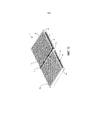
на Фиг.10 приведен общий вид спереди двухситной системы, согласно одному варианту реализации настоящего изобретения;figure 10 shows a General front view of a two-sieve system, according to one variant of implementation of the present invention;
на Фиг.11 приведен общий вид спереди частично собранной двухситной системы, согласно одному варианту реализации настоящего изобретения;11 is a general front view of a partially assembled double-screen system, according to one embodiment of the present invention;
на Фиг.12 приведен фронтальный разрез известного грохота, модернизированного с использованием четырех двухситных систем, согласно одному варианту реализации настоящего изобретения;12 is a front sectional view of a known screen upgraded using four double-screen systems, in accordance with one embodiment of the present invention;
на Фиг.13 приведен фронтальный разрез второго известного грохота, модернизированного с использованием четырех двухситных систем, согласно одному варианту реализации настоящего изобретения;FIG. 13 is a frontal sectional view of a second known screen modernized using four double-screen systems, according to one embodiment of the present invention;
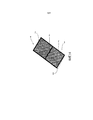
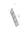
на Фиг.14 приведен общий вид сверху клиновидного узла сита, согласно одному варианту реализации настоящего изобретения;on Fig shows a General top view of the wedge-shaped node of the sieve, according to one variant of implementation of the present invention;
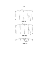
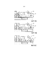
на Фиг.15А приведен схематичный вид сбоку известного грохота с основанием в нейтральном положении, модернизированного с использованием четырех плоских двухситных систем, согласно одному варианту реализации настоящего изобретения;Fig. 15A is a schematic side view of a known screen with a base in a neutral position, upgraded using four flat two-sieve systems, according to one embodiment of the present invention;
на Фиг.15В приведен схематичный вид сбоку известного грохота в положении наклона вверх, модернизированного с использованием четырех плоских двухситных систем, согласно одному варианту реализации настоящего изобретения;FIG. 15B is a schematic side view of a known screen in an upward tilt position upgraded using four flat dual-screen systems, according to one embodiment of the present invention;
на Фиг.15С приведен схематичный вид сбоку известного грохота в положении наклона вниз, модернизированного с использованием четырех двухситных систем, согласно одному варианту реализации настоящего изобретения;FIG. 15C is a schematic side view of a known screen in a downward tilted position upgraded using four dual-screen systems, according to one embodiment of the present invention;
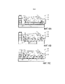
на Фиг.16А приведен схематичный вид сбоку известного грохота с основанием в нейтральном положении, модернизированного с использованием комбинации плоских и клиновидных двухситных систем, согласно одному варианту реализации настоящего изобретения;on Figa shows a schematic side view of a known screen with a base in a neutral position, upgraded using a combination of flat and wedge-shaped double-screen systems, according to one embodiment of the present invention;
на Фиг.16В приведен схематичный вид сбоку известного грохота с основанием в положении наклона вверх, модернизированного с использованием комбинации плоских и клиновидных двухситных систем, согласно одному варианту реализации настоящего изобретения;FIG. 16B is a schematic side view of a known screen with a base in an upward tilt position, upgraded using a combination of flat and wedge-shaped dual-screen systems, according to one embodiment of the present invention;
на Фиг.16С приведен схематичный вид сбоку известного грохота с основанием в положении наклона вниз, модернизированного с использованием комбинации плоских и клиновидных двухситных систем, согласно одному варианту реализации настоящего изобретения;FIG. 16C is a schematic side view of a known screen with a base in a downward inclined position, upgraded using a combination of flat and wedge-shaped double-screen systems, according to one embodiment of the present invention;
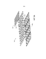
на Фиг.17 приведен вид спереди основания и сита вибрационного грохота, иллюстрирующий гармоники вибрации краев сита по сравнению с центром сита, согласно одному варианту реализации настоящего изобретения;FIG. 17 is a front view of a vibrating screen base and sieve illustrating harmonics of vibration of the edges of the sieve relative to the center of the sieve, according to one embodiment of the present invention;
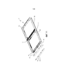
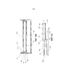
на Фиг.18 приведен общий вид опорной системы сит для использования при модернизации в ступенчатом грохоте, согласно одному варианту реализации настоящего изобретения;on Fig shows a General view of the support system of sieves for use when upgrading in a step screen, according to one embodiment of the present invention;
на Фиг.18А приведен общий вид с пространственным разделением деталей опорной системы сит для использования при модернизации в ступенчатом грохоте, иллюстрирующий опорную систему нижнего сита, опорную верхнего систему сита и сито, согласно одному варианту реализации настоящего изобретения;on Figa shows a General view with a spatial separation of the parts of the support sieve system for use in the upgrade in a step screen, illustrating the support system of the lower sieve, the support upper sieve system and sieve, according to one embodiment of the present invention;
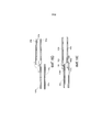
на Фиг.18В приведено схематичное сечение опорной системы сдвоенных сит с опорой нижнего сита, расположенной ниже существующих опорных кассет для сит, согласно одному варианту реализации настоящего изобретения;Fig. 18B is a schematic cross-sectional view of a support system of dual screens with a support of a lower screen located below existing support screens for screens, according to one embodiment of the present invention;
на Фиг.18С приведено схематичное сечение двух соседних сит в ступенчатой системе сит, иллюстрирующее возможный поток материала от нижнего сита к верхнему ситу, согласно одному варианту реализации настоящего изобретения;Fig. 18C is a schematic sectional view of two adjacent screens in a stepped screen system illustrating a possible material flow from the lower screen to the upper screen, according to one embodiment of the present invention;
на Фиг.18D приведено схематичное сечение двух соседних двухситных узлов в ступенчатой системе сит, иллюстрирующее возможный поток материала от нижнего сита только на верхнее сито, согласно одному варианту реализации настоящего изобретения;Fig. 18D is a schematic cross-sectional view of two adjacent double-sieve assemblies in a stepped sieve system illustrating a possible material flow from the lower sieve to only the upper sieve, according to one embodiment of the present invention;
на Фиг.18Е приведено схематичное сечение двух соседних двухситных узлов в ступенчатой системе сит, в которой верхнее сито, расположенное ниже по ходу технологического процесса, смещено относительно нижнего сита, расположенного ниже по ходу технологического процесса, согласно одному варианту реализации настоящего изобретения;Fig. 18E is a schematic sectional view of two adjacent double-sieve assemblies in a stepped sieve system in which the upper sieve located downstream of the process is offset from the lower sieve located downstream of the process, according to one embodiment of the present invention;
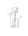
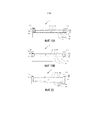
на Фиг.19А приведен вид с торца опорной системы сдвоенных сит, приспособленной для использования на основании грохота, имеющем систему крепления с зажиманием при помощи клиньев, согласно одному варианту реализации настоящего изобретения;on figa shows an end view of the support system of double sieves, adapted for use on the basis of the screen, having a fastening system with clamping with wedges, according to one embodiment of the present invention;
на Фиг.19В приведен вид с торца опорной системы сдвоенных сит, приспособленной для использования на основании грохота, имеющем систему крепления с зажиманием при помощи клиньев, согласно одному варианту реализации настоящего изобретения;FIG. 19B is an end view of a support system of dual screens adapted for use on a screening base having a clamping system with wedges, according to one embodiment of the present invention;
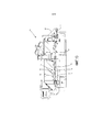
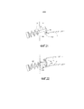
на Фиг.20 приведен вид с торца опорной системы сдвоенных сит, приспособленной для использования на основании грохота, имеющем воздушную или гидравлическую систему зажимания при помощи воздушного или гидравлического давления, согласно одному варианту реализации настоящего изобретения;FIG. 20 is an end view of a support system for dual screens adapted for use on a screening base having an air or hydraulic clamping system using air or hydraulic pressure, according to one embodiment of the present invention;
на Фиг.21 приведен вид с торца системы крепления сит при помощи крюков для прикрепления одинарного сита к основанию грохота, согласно известному уровню техники;on Fig shows an end view of the system for attaching sieves with hooks for attaching a single sieve to the base of the screen, according to the prior art;
на Фиг.22 приведен вид с торца опорной системы сдвоенных сит, приспособленной для использования на основании грохота, имеющем систему крепления сит при помощи крюков, согласно одному варианту реализации настоящего изобретения.FIG. 22 is an end view of a support system of dual screens adapted for use on a screening base having a hook fastening system for sieves, according to one embodiment of the present invention.
Подробное описание предпочтительных вариантов реализацииDetailed Description of Preferred Embodiments
Со ссылкой на чертежи описана двухситная система 10 для прикрепления к существующему вибрационному грохоту.With reference to the drawings, a dual-
Двухситная системаDual screen system
Если обратиться к Фиг.1 – Фиг.3С, двухситная система 10 содержит узел 12 верхнего сита, имеющий крупноячеистую сетку, который установлен сверху узла 14 нижнего сита, имеющего мелкоячеистую сетку, где между верхним и нижним ситами имеется канал 16. Двухситная система при ее установке в существующий грохот модернизирует этот грохот, первоначально выполненный с возможностью установки только одноуровневого сита и имеющий основание грохота, к которому двухситная система 10 прикрепляется посредством клиньев, гидравлических зажимов или устройств натяжения сит при помощи крюков. Суспензия из извлеченных промывочной жидкости и выбуренной породы подается из ствола скважины на верхнее сито, при этом большие частицы задерживаются крупноячеистым верхним ситом, в то время как частицы меньшего размера и промывочная жидкость поступают в канал 16 и на нижнее сито. Мелкоячеистая сетка нижнего сита затем разделяет суспензию, задерживая мелкие и средние частицы на нижнем сите, и промывочная жидкость протекает через нижнее сито для извлечения и повторного использования. В одном варианте размер сетки верхнего сита составляет 200 меш или менее (как правило, около 38-200 меш), в то время как размер в нижнем сите превышает 200 меш. В предпочтительном случае нижнее сито имеет размер на 50 - 100 меш больше, чем верхнее сито, который, как правило, будет находиться в диапазоне от 200 до 325 и, возможно, вплоть до 400 меш. В предпочтительном случае сито с более крупной ячейкой, расположенное сверху, со стратегической точки зрения выбирают для удаления более крупных частиц выбуренной породы, у которых скорость в момент удара, обусловленная высокими ускоряющими силами кассеты грохота, может вызвать повреждение проволоки, которая обычно используется в ситах с более мелкой ячейкой (т.е., с более высоким номером сита). Другими словами, целью является удаление как можно большего количества крупного материала на верхней деке при одновременном обеспечении возможности более мелкому материалу проходить через крупноячеистое сито, для извлечения на нижней деке.If you turn to Figure 1 - Figure 3C, the double-
Канал 16 между верхним и нижним ситами имеет высоту, достаточную для обеспечения протекания потока выбуренной породы через верхнее сито и по нижнему ситу, но также поддерживается минимального размера, чтобы получить двухситную систему, имеющую небольшой зазор с целью встраивания в существующий грохот, сконструированный для установки одинарного сита. В одном варианте канал 16 имеет высоту приблизительно ½ - 2 дюйма (12,7 – 50,8 мм). Однако высота может быть больше, если способ крепления системы не вступает в противоречие с существующими системами зажимания сит.The
Каждый узел сита обычно имеет раму 12а, 14а, имеющую поперечные элементы 12b, 14b и сетку 12с, 14с сита, опорой которой служат верх рамы и поперечных элементов. На Фиг.2 и 3 показан один продольный элемент, проходящий по длине, и три поперечных элемента, проходящих по ширине, однако для обеспечения опоры ситу можно использовать и другие конфигурации продольных и поперечных элементов, которые не обязательно будут зависеть от размера рамы. Фиг.10 иллюстрирует двухситную систему 10, имеющую один поперечный элемент на каждом из верхнего и нижнего сит.Each sieve assembly typically has a
Соединительные элементы в двухситной системеConnecting elements in a double-screen system
Узлы верхнего и нижнего сит могут составлять единую конструкцию или представлять собой два отдельных узла сит, которые нежестко соединены друг с другом. В одном варианте, показанном на Фиг.1 – Фиг.4, узлы верхнего и нижнего сит собраны вместе с использованием множества соединительных элементов 30а, 30b, прикрепленных к раме 12а, 14а, и опорных элементов 12b, 14b. Соединительные элементы 30а верхнего сита проходят от низа рамы верхнего сита и опорных элементов, и каждый из них имеет канавку 30с. Соединительные элементы 30b нижнего сита проходят от верха рамы нижнего сита и нежестко сопряжены с канавкой 30с соединительных элементов верхнего сита. Фиг.4 иллюстрирует то, как соединяются соединительные элементы верхнего и нижнего сит, за счет скольжения соединительных элементов в направлении друг друга, в результате чего соединительные элементы нижнего сита сопрягаются с соответствующими канавками на раме верхнего сита.The nodes of the upper and lower screens can be a single structure or represent two separate nodes of the sieves, which are not rigidly connected to each other. In one embodiment, shown in FIGS. 1 to 4, nodes of the upper and lower screens are assembled using a plurality of connecting
Соединительная система на основе центрального разделителя для сдвоенных ситCentral separator system for double sieves
Фиг.5А иллюстрирует альтернативный вариант двухситной системы 10, предоставляя вид спереди узла 12 верхнего сита и узла 14 нижнего сита, соединенных центральным разделителем 50. На Фиг.6А, 6В и 6С дополнительно приведены вид сверху, вид снизу и вид спереди, соответственно, узла 12 верхнего сита в этом варианте, в то время как на Фиг.7А, 7В и 7С приведены вид сверху, вид снизу и вид спереди, соответственно, узла 14 нижнего сита. На Фиг.8А, 8В и 8С дополнительно приведены вид сверху, вид снизу и вид спереди, соответственно, центрального разделителя 50. Центральный разделитель 50 соединяет узлы верхнего и нижнего сит и обеспечивает канал 16 между ситами. Центральный разделитель 50 имеет раму 50а разделителя, положение которой согласовано с положением рам 12а, 14а и поперечных элементов 12b, 14b узлов верхнего и нижнего сит и которая соединена с ними. Если обратиться к Фиг.8А, 8В и 8С, разделитель имеет верхние и нижние штыри 50b, 50с, положение которых согласовано с положением соответствующих отверстий 12d, 14d на нижней стороне верхнего сита (Фиг.6В) и верхней стороне нижнего сита (Фиг.7А), соответственно, и которые вставлены в эти отверстия.Fig. 5A illustrates an alternative dual-
Альтернативный вариант верхнего сита, имеющего направляющие для клиньев на более низком уровнеAn alternative top sieve having lower guides for wedges
Фиг.5В иллюстрирует альтернативный вариант двухситной системы 10, в которой боковые края 12е на верхней стороне рамы 12а верхнего сита смещены относительно центрального разделителя 50 и рамы 14а нижнего сита. Это облегчает встраивание двухситной системы 10 в существующий грохот и позволяет согласовать ее положение с положением направляющих для клиньев на грохоте, как более подробно рассмотрено ниже.5B illustrates an alternative dual-
Стержневая соединительная система для сдвоенных ситDouble joint sieve rod connection system
На Фиг.5С приведен вид сбоку двухситной системы, на котором показан следующий вариант соединения узла 12 верхнего сита и узла 14 нижнего сита с использованием стержневых соединителей 60. Стержневые соединители дополнительно показаны на Фиг.9А, 9В и 9С, на которых приведены вид сверху, вид снизу и вид спереди, соответственно. Положение стержневых соединителей согласовано с положением, по меньшей мере, некоторых из поперечных элементов 12b, 14b и, по меньшей мере, с частью рам 12а, 14а сит. В отличие от центрального разделителя 50, показанного на Фиг.8А, 8В и 8С, этот способ соединения, в котором используются стержневые соединители 60, не имеет рамы разделителя. Вместо этого стержневые соединители 60 индивидуально прикрепляются к поперечным элементам и рамам верхнего и нижнего сит, чтобы соединить эти два сита. Аналогично системе на основе центрального разделителя, стержневые соединители имеют верхние и нижние штыри 60b, 60с для согласования положения и сопряжения с отверстиями 12d, 14d в рамах и поперечных элементах сит.Fig. 5C is a side view of a two-sieve system, showing the following embodiment of the connection of the
На Фиг.10 приведен общий вид двухситной системы, соединенной при помощи стержневых соединителей 60. На Фиг.11 показан альтернативный вариант двухситной системы, имеющей стержневые соединители 60 с соединительными элементами 62, которые могут с получением нежесткого соединения сопрягаться с соединительными элементами 30 нижнего сита и соединительными элементами верхнего сита (не показаны).Figure 10 shows a General view of a two-sieve system connected by means of
Чтобы предотвратить относительное скольжение узлов верхнего и нижнего сит, когда они состоят из двух частей, между узлами верхнего и нижнего сит можно установить резиновый элемент, который в комбинации с давлением от системы крепления (например, системы крепления при помощи клиньев или зажимания), поддерживает верхнее и нижнее сита в должной ориентации друг относительно друга.To prevent the relative sliding of the upper and lower sieves when they consist of two parts, a rubber element can be installed between the nodes of the upper and lower sieves, which, in combination with pressure from the fastening system (for example, fastening systems using wedges or clamping), supports the upper and lower sieves in proper orientation with respect to each other.
Могут быть использованы и другие способы соединения верхнего и нижнего сит, что известно специалисту в данной области техники, включая соединение болтами, сварку, соединение заклепками или склеивание.Other methods of joining the upper and lower screens may be used, as is known to those skilled in the art, including bolting, welding, riveting or gluing.
МодернизацияModernization
Двухситная система 10 может быть приспособлена для работы в существующих грохотах без каких-либо существенных модификаций, необходимых для грохота. Определенные грохоты могут не требовать модификации, в то время как другие грохоты могут потребовать репозиционирования системы крепления, например, направляющих для клиньев, гидравлического оборудования или крюков, которые фиксируют систему сит на месте в кассете грохота, и/или добавления блокирующей пластины на входном торце грохота для размещения системы сит большей высоты, как рассмотрено ниже.The dual-
Фиг.12 иллюстрирует типичный известный грохот 20, имеющий входной торец 20а, где в грохот поступает суспензия из выбуренной породы и промывочной жидкости, и выходной торец 20b, где из грохота выходят разделенные выбуренная порода и промывочная жидкость. Грохот также включает ряд лож 24 грохота, в этом случае - четыре, служащих опорой отдельным ситам грохота, согласно известному уровню техники, и кассету 27 грохота для размещения внутри ее лож и сит грохота и сообщения им вибрационного перемещения. Система крепления изображена как направляющие 26 для клиньев, которые фиксируют сита на ложах 24 грохота. Когда суспензия, содержащая породу, поступает с входного торца 20а грохота, она, как правило, падает на контактную пластину 39, которая поглощает удар и направляет суспензию на верх первого сита, расположенного рядом с входным торцом грохота.12 illustrates a typical known
Согласно изобретению, известный грохот 20 модернизируют, используя ряд двухситных систем 10, причем каждая система сит имеет впускной торец 10а и выпускной торец 10b и соединена с ложами 24 грохота при помощи направляющих 26 для клиньев. В этом варианте каждый узел 12 верхнего сита включает выступ 18 на выпускном торце для направления потока выбуренной породы и промывочной жидкости от выпускного торца на верхнюю поверхность 12f впускного торца соседнего узла верхнего сита. Выступ предотвращает протекание потока выбуренной породы и промывочной жидкости в зазор 28 между двухситными системами, либо в канал 16 между узлом 12 верхнего сита и узлом 14 нижнего сита. Выступ 18 на верхнем сите 12 также показан на Фиг.6А и 6В.According to the invention, the known
Если двухситная система 10 установлена в существующем грохоте, и верхняя поверхность 12f первого верхнего сита 12g расположена выше существующей контактной пластины 39, то в качестве модернизации выше контактной пластины в первый узел сита устанавливается блокирующая пластина 38 или аналогичное устройство, чтобы предотвратить такую ситуацию с целью направления потока, содержащего породу, на верхнюю поверхность 12f верхнего сита в первой двухситной системе. Это гарантирует, что крупные частицы не будут контактировать с первым нижним ситом.If the double-
Следующий вариант известного грохота 20, модернизированного с использованием двухситных систем по настоящему изобретению, изображен на Фиг.13.A further embodiment of the known
Преимущества двухситной системыAdvantages of the dual-screen system
Двухситная система предпочтительно является модульной, что позволяет заменять верхнее и/или нижнее сита, исходя из свойств обрабатываемой суспензии, чтобы оптимизировать отделение выбуренной породы от промывочной жидкости. Это позволяет оператору выбирать оптимальный размер сетки, материал сита, конфигурацию и угол наклона как для узла верхнего сита, так и для узла нижнего сита. Это также делает возможным для оператора легко восстанавливать и/или заменять компоненты узла верхнего сита или узла нижнего сита без необходимости замены всей двухситной системы, если узлы сит не скреплены на постоянной основе в один блок. Важным является то, что это позволяет заменить только необходимые компоненты сита из-за неравномерного износа узлов верхнего и нижнего сит в двухситной системе.The double-sieve system is preferably modular, which allows you to replace the upper and / or lower sieves, based on the properties of the processed suspension, in order to optimize the separation of cuttings from the wash fluid. This allows the operator to select the optimal mesh size, sieve material, configuration, and tilt angle for both the top sieve assembly and the lower sieve assembly. It also makes it possible for the operator to easily repair and / or replace the components of the top sieve assembly or the lower sieve assembly without having to replace the entire dual-sieve system if the sieve assemblies are not permanently bonded into one unit. It is important that this allows you to replace only the necessary components of the sieve due to uneven wear of the nodes of the upper and lower sieves in a two-sieve system.
При известном уровне техники часто используют последовательность из грохотов для постепенного отделения промывочной жидкости от выбуренной породы по мере прохождения суспензии через эту последовательность. При замене одинарного сита в грохоте двухситной системой, соответствующей настоящему изобретению, двухситная система потенциально способна обрабатывать двойной объем суспензии за то же время, по существу, с теми же требованиями по расходу энергии, что и односитная система. Это уменьшает число грохотов, которые требуются, и снижает связанные с ними требования по времени, затратам и пространству. Таким образом, двухситная система создает более эффективную и экономичную систему разделения промывочных жидкостей и выбуренной породы. При полевых испытаниях, когда грохот, который с трудом справлялся с расходом 0,5 м3/мин выбуренной породы/промывочной жидкости при использовании одинарного сита размером 200 меш по стандарту API (American Petroleum Institute, Американский нефтяной институт), имел установленную двухситную систему с верхним ситом по стандарту 80 API и нижнее сито по стандарту 200 API, двухситная система была способна обрабатывать расходы суспензии более 1,5 м3/мин.In the prior art, a sequence of screens is often used to gradually separate the washing liquid from the cuttings as the suspension passes through this sequence. When replacing a single sieve in a screen with a two-sieve system according to the present invention, the two-sieve system is potentially capable of processing a double volume of slurry at the same time, with substantially the same energy requirements as a single-sieve system. This reduces the number of screens required and reduces the time, cost and space requirements associated with them. Thus, the two-sieve system creates a more efficient and economical system for the separation of washing fluids and drill cuttings. In field trials, when a screen that could hardly cope with a flow rate of 0.5 m 3 / min of cuttings / flushing fluid using a single mesh 200 mesh sieve according to API standard (American Petroleum Institute, American Petroleum Institute), had a two-sieve system with with a top sieve of 80 API standard and a lower sieve of 200 API standard, a two-sieve system was able to handle slurry flow rates of more than 1.5 m 3 / min.
Наклонное ситоInclined Screen
В одном варианте узел верхнего сита или узел нижнего сита наклонен, чтобы получить "клиновидное" сито 40, показанного на Фиг.14, для создания в грохоте узла с ситом, наклоненным вверх или вниз. Аналогично плоским узлу 12 верхнего сита и узлу 14 нижнего сита, показанным на Фиг.1, 2А и 3А, узел 40 клиновидного сита имеет раму 40а с поперечным элементом 40b и сеткой 40с сита, при этом разница заключается в том, что рама, поперечный элемент (элементы) и сито наклонены под углом относительно горизонтали, чтобы получить толстый торец 40d и конусный торец 40е. В предпочтительном случае угол сита находится между –6 и +6 градусами.In one embodiment, the top sieve assembly or the lower sieve assembly is tilted to obtain a wedge-shaped
В следующем варианте наклонены как узел верхнего сита, так и узел нижнего сита. Сита могут быть наклонены в одном и том же направлении или в противоположных направлениях. Двухситные системы 10, установленные в грохотах 20, показанных на Фиг.12 и 13, имеют клиновидные верхнее и нижнее сита, где нижние сита наклонены вниз, а верхние сита наклонены вверх.In a further embodiment, both the upper sieve assembly and the lower sieve assembly are tilted. The sieves can be tilted in the same direction or in opposite directions. The double-
Преимущества наклонного ситаBenefits of Inclined Screen
Узел с клиновидным ситом изменяет динамику и расход промывочной жидкости и выбуренной породы по ситам. При наклоне сита вниз скорость потока увеличивается, что особенно полезно, когда суспензия на сите является вязкой или похожей на сало. Наклон узла сита вверх уменьшает скорость потока, выделяя суспензии больше времени на проход по ситу, что может повысить степень отделения промывочной жидкости от выбуренной породы. Угол наклона и направление наклона узлов верхнего и нижнего сит могут быть изменены независимо, исходя из свойств суспензии, чтобы оптимизировать эффективность обработки в грохоте. Эта конструкция предназначена для областей применения как с одинарным, так и со сдвоенными ситами и ранее не рассматривалась.A node with a wedge-shaped sieve changes the dynamics and flow rate of washing liquid and cuttings by sieves. By tilting the sieve downward, the flow rate increases, which is especially useful when the suspension on the sieve is viscous or similar to lard. Tilting the sieve assembly upward reduces the flow rate, giving the suspension more time to pass through the sieve, which can increase the degree of separation of the washing fluid from the cuttings. The angle of inclination and the direction of inclination of the nodes of the upper and lower screens can be changed independently, based on the properties of the slurry, in order to optimize the processing efficiency in the screen. This design is intended for applications with both single and double screens and has not been previously considered.
При известном уровне техники имеются кассеты грохота, которые можно наклонять в направлении вверх или вниз, чтобы изменить расход суспензии, перемещающейся по ситам грохота. Если сделать возможной индивидуальную модификацию отдельных сит и углов грохота, можно дополнительно индивидуализировать расход в различных точках на ситах грохота. Кроме того, изменение угла сит грохота позволяет регулировать расход в грохотах, в которых нельзя наклонить кассету грохота. На Фиг.15А, 15В и 15С изображен известный грохот 20 с наклоняемой кассетой 22, содержащей четыре ложа 24 грохота. На Фиг.15А кассета изображена в нейтральном положении; на Фиг.15В кассета изображена в положении наклона вверх; и на Фиг.15С кассета изображена в положении наклона вниз. Как можно видеть, при наклоне кассеты наклоняются все ложа 24 грохота, под тем же углом, что и кассета грохота, и в системе нет возможности индивидуально модифицировать каждое ложе грохота. В отличие от этого, и в соответствии со следующим вариантом реализации настоящего изобретения, те же грохоты 20, кассета 22 которых находится в нейтральном положении (Фиг.16А), положении наклона вверх (Фиг.16В) или положении наклона вниз (Фиг.16С), модернизируются с использованием комбинации из плоских двухситных систем 10 и либо клиновидных сдвоенных сит 42 с наклоном вверх, либо клиновидных сдвоенных сит 44 с наклоном вниз, чтобы дополнительно индивидуализировать расход суспензии, перемещающейся по ситам грохота.In the prior art, there are screening cassettes that can be tilted up or down to change the flow rate of the slurry moving along the screening screens. If individual modification of individual screens and screen angles is possible, it is possible to further individualize the flow rate at various points on the screen screens. In addition, changing the angle of the screen allows you to adjust the flow in screens in which you cannot tilt the screen cassette. On Figa, 15B and 15C depicts a known
В известных ситах 32 вибрационного грохота, как изображено на Фиг.17, края 32а узла сита удерживаются на месте на ложе 24 грохота при помощи системы 26 крепления, которая может включать клинья, гидравлические зажимы или натягивающие крюки, при этом центр 32b сита напрямую не прижимается к ложу грохота, поддержание контакта в центре ложа зависит от давления на краю и собственной жесткости этого центра. Когда ложе грохота и система крепления вибрируют с заданными частотой и амплитудой, показанными стрелкой 34, края сита, как правило, вибрируют с теми же частотой и амплитудой, тогда как центр сита, будучи расположенным дальше от системы крепления, как правило, вибрирует с пониженными частотой и амплитудой, показанными стрелкой 36. Это часто вызывает вихрение выбуренной породы в центре сита, вместо перемещения по относительно прямой линии по ситу, создавая больший износ в центре сита по сравнению с краями сита. Когда центр сита изнашивается, заменять необходимо сито целиком, даже несмотря на то, что края сита могут еще послужить. Использование клиновидного сита влияет на гармоники вибраций, так как центр сита уже, чем периферия сита, и эффект вихрения в центре сита уменьшается, продлевая срок службы сита.In known vibrating screen sieves 32, as shown in FIG. 17, the edges of the
Опорная система ситSieve support system
На Фиг.18В приведено сечение опорной системы 100 сит в кассете 22 грохота. Как показано на Фиг.18В, опорой каждому ситу служат опорные кронштейны 102 сит на обеих боковых сторонах кассеты грохота и, как правило, сита удерживаются на месте клиньями 104. Клин 104, как правило, будет закрепляться между плоской верхней поверхностью сита и угловым кронштейном 106, выступающим от боковой стороны кассеты грохота над опорными кронштейнами сит. Соответственно, путем продвижения клиньев в пространство ниже угловых кронштейнов и сита можно зафиксировать сита на месте.FIG. 18B is a cross-sectional view of the
Чтобы эффективным образом модернизировать существующий грохот, использующий существующую систему клиньев, путем установки опорной системы 100 сдвоенных сит, предпочтительно, чтобы верхнее сито не полностью занимало пространство для клина, в результате чего можно использовать аналогичные клинья (или, по меньшей мере, более узкие клинья). Соответственно, как показано на Фиг.18В, предпочтительно, чтобы опорная система 100а нижнего сита находилась ниже опорных кронштейнов 102 сит. Однако использование углового профиля или эквивалента на боковой стороне верхнего сита, как показано на Фиг.5В, может это компенсировать.In order to efficiently upgrade an existing screen using the existing wedge system by installing a support system of 100 double screens, it is preferable that the top screen does not completely occupy the wedge space, whereby similar wedges (or at least narrower wedges) can be used . Accordingly, as shown in FIG. 18B, it is preferable that the lower
Как показано, опорная система 100а нижнего сита имеет меньшую ширину по сравнению с шириной кассеты 22 грохота, что позволяет расположить верхнюю поверхность опорной системы 100а нижнего сита и нижнее сито 108 ниже опорных кронштейнов 102 сит. Опоры 100с, 100d выполнены с возможностью обеспечения вертикального расстояния разделения между нижним ситом 108а и верхним ситом 108b и посадочного места, обеспечивающего опору системе, на опорных кронштейнах 102 сит. Для ясности другие опоры в срединной части, которые могут быть включены, на Фиг.18В опущены.As shown, the lower
В различных вариантах опорную систему сит сваривают, сболчивают или склеивают вместе, чтобы обеспечить опору двум слоям сит, и она может быть собрана как единая рама.In various embodiments, the support sieve system is welded, crushed, or glued together to support two layers of sieves, and it can be assembled as a single frame.
Как показано на Фиг.18А, верхнее сито 108b подогнано под опору 100b верхнего сита. Аналогичные сита подогнаны под полные поверхности верхней рамы и поверхности нижней рамы.As shown in FIG. 18A, the
Сдвоенные сита для использования в грохоте с со ступенчатыми или каскадными ситамиDouble screens for use in screens with step or cascade screens
Как описано выше, некоторые системы грохотов обеспечивают ступенчатую конфигурацию в кассете грохота, в результате чего выбуренная порода по ступеням опускается вниз по мере прохождения по отдельным ситам основания грохота. В таких грохотах со ступенчатыми или каскадными ситами может применяться двухситная система по настоящему изобретению. Как показано на Фиг.18 и 18А, опорная система 100 сдвоенных сит для использования в ступенчатом грохоте может содержать последовательность из отдельных опорных систем, которые смещены друг относительно друга по вертикали. На Фиг.18 показана собранная опорная система сдвоенных сит, а на Фиг.18А показана опорная система сдвоенных сит с частичным пространственным разделением деталей.As described above, some screening systems provide a stepwise configuration in the screening cassette, as a result of which the cuttings go down in steps as they pass through the individual screens of the screening base. In such screens with step or cascade screens, the double-screen system of the present invention can be used. As shown in FIGS. 18 and 18A, the
На Фиг.18С показано то, как поток из выбуренной породы и промывочной жидкости может двигаться вперед по последовательности ступенчатых рам. Важным является то, что верхнее и нижнее сита 108а, 108b будут включать удлинение 108с, которое проходит за край опорной рамы 100а, 100b, чтобы гарантировать, что выбуренная порода/промывочная жидкость будут протекать на следующее сито. В дополнение к этому, предпочтительно, чтобы между опорной рамой 100b верхнего сита и верхним ситом 108b, расположенным ниже по ходу технологического процесса, существовал первый зазор 109, в результате чего, если объем промывочной жидкости/выбуренной породы на нижнем сите 108а является высоким, такой объем материала может протекать из области нижнего сита на сито, расположенное ниже по ходу технологического процесса, через первый зазор 109.On Figs shows how the flow of cuttings and drilling fluid can move forward along a sequence of stepped frames. It is important that the upper and
В другом варианте, показанном на Фиг.18Е, второй зазор или канал 109b', находящийся между нижними ситами 108а, 108а', расположенными выше и ниже по ходу технологического процесса, может быть увеличен за счет смещения расположенного выше по ходу технологического процесса торца 108bi' верхнего сита 108b', расположенного ниже по ходу технологического процесса, относительно расположенного выше по ходу технологического процесса торца 108ai' нижнего сита 108a', расположенного ниже по ходу технологического процесса. Удлинение 108с на верхнем сите 108b, расположенном выше по ходу технологического процесса, гарантирует, что выбуренная порода/промывочная жидкость с этого сита протекают на верхнее сито 108b', расположенное ниже по ходу технологического процесса, вместо протекания на нижнее сито 108а', расположенное ниже по ходу технологического процесса. Этот вариант позволяет уменьшить разницу по высоте между ступенчатыми ситами, расположенными выше и ниже по ходу технологического процесса, в то же время, по-прежнему делая возможным существование эффективного потока между ситами, расположенными выше и ниже по ходу технологического процесса. Меньшая разница по высоте означает, что верхнее сито имеет более низкий профиль, что позволяет лучше встроить двухситную систему в существующую систему крепления к ложам грохота. Например, если система крепления представляет собой систему зажимания при помощи клиньев, более низкий профиль позволяет использовать клинья большего размера для удерживания двухситной системы на месте. Как показано на Фиг.18Е, между верхними ситами 108b, 108b', расположенными выше и ниже по ходу технологического процесса, по-прежнему существует первый зазор 109, чтобы позволить избыточному объему выбуренной породы/промывочной жидкости на нижнем сите 108а, расположенном выше по ходу технологического процесса, протекать на верхнее сито 108b', расположенное ниже по ходу технологического процесса, в случае, если недостаточно пространства для протекания на нижнее сито 108a', расположенное ниже по ходу технологического процесса.In another embodiment, shown in FIG. 18E, the second gap or
В качестве альтернативы, как показано на Фиг.18D, ступенчатые сита могут быть позиционированы таким образом, что выбуренная порода/промывочная жидкость с нижнего и верхнего сит 108а, 108b, расположенных выше по ходу технологического процесса, будут протекать только на верхнее сито 108b', расположенное ниже по ходу технологического процесса, и будет предотвращаться их протекание непосредственно на нижнее сито 108a', расположенное ниже по ходу технологического процесса.Alternatively, as shown in FIG. 18D, the step sieves can be positioned so that the cuttings / flushing fluid from the lower and
Важным является то, что при размещении сит с более крупной ячейкой и, следовательно, более прочных на верхних поверхностях сита с более мелкой ячейкой на нижних поверхностях будут защищаться от частиц выбуренной породы большего размера и, следовательно, срок службы сит с более мелкой ячейкой может быть увеличен.It is important that when placing sieves with a larger mesh and, therefore, more durable on the upper surfaces of the sieves with a smaller mesh on the lower surfaces will be protected from particles of drill cuttings of a larger size and, therefore, the life of the sieves with a smaller mesh can be increased.
Необходимо отметить, что можно встроить более двух опорных систем сит, если соображения по пространству делают возможной такую конфигурацию.It should be noted that more than two support sieve systems can be built in if space considerations make such a configuration possible.
Сдвоенные сита грохота для грохотов с плоским ложем ситаDouble screening sieves for flat bed screens
В еще одном варианте двухситные системы с целью модернизации могут быть установлены в грохот, имеющий плоское некаскадное ложе сита для получения двухситной системы, имеющей каскадный эффект между соседними ситами. В этом случае двухситная система, расположенная выше по ходу технологического процесса, будет возвышаться над нормальным уровнем ложа сита, и каждая последующая двухситная система, расположенная ниже по ходу технологического процесса, располагается на более низком уровне, в результате чего выбуренная порода может опускаться вниз по ступеням. В этом случае, как схематично показано на Фиг.18, будут включены дополнительные опорные элементы 110, в результате чего каждая двухситная система располагается на отличной от других высоте. В этом случае грохот, имеющий плоское ложе сита, может быть модернизирован, чтобы сделать возможным прохождение породы через полученный зазор 109, как описано выше. Более того, верхнее сито может быть наклонено вверх под углом приблизительно 1°-3° в направлении потока. Это гарантирует, что на плоских или каскадных деках выпускной конец идущего первым верхнего сита находится выше впускной стороны следующего сита.In yet another embodiment, dual-sieve systems for the purpose of modernization can be installed in a screen having a flat non-cascade bed of sieves to obtain a two-sieve system having a cascade effect between adjacent sieves. In this case, the two-sieve system located upstream of the process will rise above the normal bed level, and each subsequent two-sieve system located downstream of the process will be located at a lower level, as a result of which the cuttings can fall down the steps . In this case, as shown schematically in FIG. 18,
В качестве альтернативы, двухситная система может использоваться в грохоте с плоским ложем сита без позиционирования сдвоенных сит каскадным образом. Известный грохот, как правило, будет иметь одинарное сито, проходящее от торца грохота, расположенного выше по ходу технологического процесса, до торца грохота, расположенного ниже по ходу технологического процесса, и может иметься одно ложе сита или множество лож сит, установленных как параллельные деки одна сверху другой или в другой конфигурации. Двухситная система по настоящему изобретению может быть использована в таком грохоте в результате замены одного или более сит на одно или более сдвоенных сит, которые проходят вдоль всего ложа сит. В этом варианте не будет зазора между соседними секциями верхних сит, либо соседними секциями нижних сит, так как каждое верхнее сито будет, по существу, непрерывным, как и каждое нижнее сито.Alternatively, the double-sieve system can be used in a screen with a flat bed of sieves without positioning the double sieves in a cascading manner. A known screen, as a rule, will have a single sieve passing from the end of the screen located upstream of the process to the end of the screen located downstream of the process, and there may be one bed of sieves or multiple beds installed as parallel decks one on top of another or in a different configuration. The double-sieve system of the present invention can be used in such a screen by replacing one or more sieves with one or more double sieves that extend along the entire bed of sieves. In this embodiment, there will be no gap between adjacent sections of the upper sieves or adjacent sections of the lower sieves, since each upper sieve will be essentially continuous, like each lower sieve.
В другом варианте ложе сита может быть криволинейным вместо плоского, например, выпуклым. Кроме того, двухситная система может включать одно или более трехмерных сит, например, пирамидальное сито. Такое сито может использоваться для увеличения площади поверхности сита.In another embodiment, the bed of the sieve may be curved instead of flat, for example, convex. In addition, the two-sieve system may include one or more three-dimensional sieves, for example, a pyramidal sieve. Such a sieve can be used to increase the surface area of the sieve.
Альтернативные варианты систем крепленияAlternative mounting systems
Как рассмотрено в разделе "Уровень техники", одинарные сита, соответствующие известному уровню техники, прикрепляют к системам грохотов, используя различные системы крепления, которые могут включать системы зажимания при помощи клиньев, системы зажимания при помощи пластин, на которые воздействует гидравлическое давление, и системы натяжения сит при помощи крюков. Системы грохотов, имеющие любую из этих систем крепления, могут быть модернизированы для установки двухситной системы по настоящему изобретению, включая двухситные системы, изготовленные как единая конструкция (т.е., одноэлементная двухситная система) или несколько конструкций (т.е., двухэлементная двухситная система). Примерная двухситная система по настоящему изобретению, которая удерживается на месте с использованием системы зажимания при помощи клиньев, показана на Фиг.18В и рассмотрена выше.As discussed in the Background Section, prior art single sieves are attached to screening systems using various attachment systems, which may include wedge clamping systems, plate-clamping clamping systems, and systems strainer sieves with hooks. Screening systems having any of these attachment systems can be upgraded to install the dual-screen system of the present invention, including dual-screen systems made as a single structure (i.e., a single-element double-screen system) or several structures (i.e., a two-element double-screen system). An exemplary two-screen system of the present invention, which is held in place using a wedge clamping system, is shown in FIG. 18B and discussed above.
На Фиг.19А приведен вид с торца другого варианта двухситной системы 10, имеющей канал 16 между узлом 12 верхнего сита и узлом 14 нижнего сита, причем двухситная система приспособлена для закрепления в существующей кассете 22 грохота, имеющей систему крепления с зажиманием при помощи клиньев. На каждой боковой стороне кассеты грохота находится опорный кронштейн 102 сит для обеспечения опоры кронштейну 108е крепления, который проходит от каждой боковой стороны двухситной системы. Кронштейн крепления может содержать один или более элементов, соединенных с одной или обеими рамами 12а, 14а нижнего и верхнего сит. На левой боковой стороне двухситной системы на Фиг.19А показан клин 104, удерживающий опорную систему сдвоенных сит на месте между опорным кронштейном 102 сит и верхним кронштейном 110, который, как правило, прикреплен к кассете грохота. На правой боковой стороне клин отсутствует, что позволяет вставлять двухситную систему в кассету грохота или удалять из нее. Узел верхнего сита может быть меньше по ширине, чем кассета грохота, в результате чего он не доходит до краев кассеты грохота, что создает зазор G между краем узла верхнего сита и стенкой кассеты грохота, позволяя клину с высотой Н фиксировать двухситную систему, причем высота Н имеет ту же величину, которая могла бы использоваться для фиксации обычной односитной системы в той же кассете грохота.FIG. 19A is an end view of another embodiment of a two-
В качестве альтернативы, Фиг.19В иллюстрирует двухситную систему 10, в которой узел 12 верхнего сита проходит до стенки кассеты грохота. Соответственно, для фиксации двухситной системы в кассете грохота понадобится более короткий клин, имеющий высоту Н1, если опорный кронштейн 102 сит и верхний кронштейн 110 не перемещаются.Alternatively, FIG. 19B illustrates a dual-
Фиг.20 иллюстрирует двухситную систему 10, приспособленную для использования в кассете 22 грохота, имеющей систему зажимания при помощи гидравлического или воздушного давления. Система зажимания включает плунжер 116 на каждом краю кассеты 22 грохота, который перемещается вниз, чтобы зажать кронштейн 108е крепления двухситной системы 10 между плунжером и опорным кронштейном 102 сит. С левой стороны на Фиг.20 плунжер показан в положении зажимания, в котором он удерживает двухситную систему на месте, в то время как с правой стороны плунжер находится в открытом положении, которое используется для вставки или удаления двухситной системы. На этом чертеже изображены различные опорные элементы 12b, 14b верхнего и нижнего сит.FIG. 20 illustrates a
Фиг.21 иллюстрирует систему сит с крюками, соответствующую известному уровню техники, для крепления и натяжения одинарного сита 32. На каждой боковой стороне кассеты грохота система сит с крюками включает крюк 124, прикрепленный к тяге 126, которая проходит через отверстие 128 в стенке 22b кассеты грохота. Крюк прикрепляют к соответствующему крюку 122 сита, находящемуся на краю сита, что позволяет растягивать сито с большой силой, чтобы зафиксировать его на месте в кассете и обеспечить его натяжение. Фиг.21 иллюстрирует пружинную систему 130 для создания натяжения в системе крепления сит при помощи крюков. Однако, как известно специалисту в данной области техники, для приложения силы к тяге можно использовать и другие типы систем, например, узел из болта и винта или узел воздушного или гидравлического плунжера.FIG. 21 illustrates a prior art sieve hook system for securing and tensioning a
Система крепления сит при помощи крюков, соответствующая известному уровню техники, может быть приспособлена для фиксации двухситной системы 10 по настоящему изобретению в кассете грохота. Один вариант такой процедуры показан на Фиг.22, где крюк 124 снабжен как верхним, так и нижним крюками 124а, 124b, которые выполнены с возможностью соединения с соответствующими крюками 122а, 122b в узле 12 верхнего сита и узле 14 нижнего сита, соответственно. В этом варианте верхний крюк 124а и соответствующий крюк 122а перевернуты, т.е. находятся в обратном положении, по сравнению с нижним крюком 124b и соответствующим крюком 122b. В качестве альтернативы, верхний крюк и нижний крюк могут иметь одну и ту же ориентацию, чтобы использовать один и тот же соответствующий крюк 122а, 122b в узлах верхнего и нижнего сит. Кроме того, известная система крюков может быть сохранена, и в кассете грохота выше существующей системы крюков может быть установлена вторая система крюков для крепления узла верхнего сита и создания в нем натяжения.The hook fastening system for sieves according to the prior art can be adapted to fix the double-
Результаты испытанийTest results
Были проведены испытания, чтобы определить разницу в коэффициенте удержания жидкости в породе для одинарного сита, соответствующего известному уровню техники, по сравнению со сдвоенными ситами, соответствующими настоящему изобретению, с использованием одного и того же грохота и одной и той же смеси промывочной жидкости/выбуренной породы. Испытание проводилось в соответствии с промышленными стандартами. Результаты показали, что одинарное сито имело коэффициент удержания в породе (измеряется в м3 раствора/м3 породы) 0,894, в то время как сдвоенные сита имели более низкий коэффициент удержания 0,818. Во время испытания одинарное сито было наклонено против направления потока жидкости/породы под углом +2 единицы измерения наклона в грохоте, тогда как сдвоенные сита были наклонены в направлении потока под углом –1. Эта разница в угле сита в действительности будет обеспечивать преимущество односитной системы для отделения выбуренной породы от промывочной жидкости по сравнению с двухситной системой, так как порода/жидкость будут удерживаться на одинарном сите в течение более длительного периода времени, что обусловлено наклоном против направления потока.Tests were conducted to determine the difference in the fluid retention coefficient in the rock for a single sieve according to the prior art, compared with the twin sieves of the present invention using the same screen and the same drilling fluid / cuttings mixture . The test was conducted in accordance with industry standards. The results showed that a single sieve had a rock retention rate (measured in m 3 of solution / m 3 of rock) of 0.894, while twin sieves had a lower retention rate of 0.818. During the test, a single sieve was tilted against the direction of fluid / rock flow at an angle of +2 units of slope in the screen, while dual sieves were tilted in the direction of flow at an angle of –1. This difference in sieve angle will in fact provide the advantage of a single-sieve system for separating drill cuttings from the washing liquid compared to a two-sieve system, since the rock / liquid will be held on a single sieve for a longer period of time, which is due to an inclination against the direction of flow.
Хотя настоящее изобретение описано и проиллюстрировано со ссылкой на предпочтительные варианты его реализации и предпочтительные варианты его использования, оно не должно таким образом ограничиваться, так как в него могут быть внесены модификации и изменения, не выходящие за пределы полного предполагаемого объема изобретения, как будет понятно специалистам в данной области техники.Although the present invention has been described and illustrated with reference to preferred embodiments and preferred uses thereof, it should not be so limited as modifications and changes may be made thereto without departing from the full intended scope of the invention, as will be appreciated by those skilled in the art. in the art.
Claims (45)
Applications Claiming Priority (7)
| Application Number | Priority Date | Filing Date | Title |
|---|---|---|---|
| US201361870687P | 2013-08-27 | 2013-08-27 | |
| US61/870,687 | 2013-08-27 | ||
| US201461936119P | 2014-02-05 | 2014-02-05 | |
| US61/936,119 | 2014-02-05 | ||
| US201462008868P | 2014-06-06 | 2014-06-06 | |
| US62/008,868 | 2014-06-06 | ||
| PCT/CA2014/000655 WO2015027321A1 (en) | 2013-08-27 | 2014-08-26 | Dual screen assembly for vibrating screening machine |
Publications (3)
| Publication Number | Publication Date |
|---|---|
| RU2016111109A RU2016111109A (en) | 2017-10-03 |
| RU2016111109A3 RU2016111109A3 (en) | 2018-05-17 |
| RU2676103C2 true RU2676103C2 (en) | 2018-12-26 |
Family
ID=52585326
Family Applications (1)
| Application Number | Title | Priority Date | Filing Date |
|---|---|---|---|
| RU2016111109A RU2676103C2 (en) | 2013-08-27 | 2014-08-26 | Dual screen system for connection with screening machine (versions) |
Country Status (10)
| Country | Link |
|---|---|
| US (3) | US9908149B2 (en) |
| CN (1) | CN105579151B (en) |
| AU (2) | AU2014311218B2 (en) |
| BR (1) | BR112016004521A8 (en) |
| CA (1) | CA2921506C (en) |
| GB (1) | GB2532173B (en) |
| MX (2) | MX2016002215A (en) |
| NO (1) | NO342702B1 (en) |
| RU (1) | RU2676103C2 (en) |
| WO (1) | WO2015027321A1 (en) |
Cited By (1)
| Publication number | Priority date | Publication date | Assignee | Title |
|---|---|---|---|---|
| US12139980B2 (en) | 2019-12-19 | 2024-11-12 | Schlumberger Technology Corporation | Deck assemblies for vibratory separators |
Families Citing this family (16)
| Publication number | Priority date | Publication date | Assignee | Title |
|---|---|---|---|---|
| US9908149B2 (en) | 2013-08-27 | 2018-03-06 | Fp Canmechanica Inc. | Dual screen assembly for vibrating screening machine |
| CN106064147A (en) * | 2016-07-20 | 2016-11-02 | 柳州六品科技有限公司 | A kind of adjustable for height vibrosieve |
| CN106064148A (en) * | 2016-07-20 | 2016-11-02 | 柳州六品科技有限公司 | A kind of vibrosieve |
| US11806755B2 (en) | 2016-10-14 | 2023-11-07 | Derrick Corporation | Apparatuses, methods, and systems for vibratory screening |
| USD890236S1 (en) | 2019-02-07 | 2020-07-14 | Derrick Corporation | Vibratory screening machine |
| JOP20190082A1 (en) | 2016-10-14 | 2019-04-14 | Dirrick Corp | Equipment, methods and systems for vibratory sorting |
| US11052427B2 (en) | 2016-10-14 | 2021-07-06 | Derrick Corporation | Apparatuses, methods, and systems for vibratory screening |
| US11185801B2 (en) | 2016-10-14 | 2021-11-30 | Derrick Corporation | Apparatuses, methods, and systems for vibratory screening |
| EA202091698A3 (en) * | 2017-04-21 | 2021-01-29 | Деррик Корпорейшн | VIBRATING SCREEN, SIEVE DECK UNIT AND METHOD FOR SCREENING MATERIAL |
| US10471472B2 (en) * | 2017-06-08 | 2019-11-12 | Terex Usa, Llc | Method and apparatus for supplying support from below to a screen cloth on a vibrating screening machine |
| US11305316B2 (en) | 2017-06-08 | 2022-04-19 | Terex Usa, Llc | Method and apparatus for supplying support from below to a screen cloth on a vibrating screening machine |
| US11052428B2 (en) * | 2019-06-27 | 2021-07-06 | Schlumberger Technology Corporation | Snap in screen and method |
| CN113426187A (en) * | 2021-07-28 | 2021-09-24 | 安平县光明金属制品有限公司 | High-efficient double-deck mud vibration screen cloth of replacing |
| US20230366279A1 (en) * | 2022-05-16 | 2023-11-16 | National Oilwell Varco, L.P. | Shale shakers and related methods |
| CN114932078B (en) * | 2022-06-02 | 2023-04-28 | 南宁职业技术学院 | Metal powder screening plant of 3D printing |
| CN115025980A (en) * | 2022-06-22 | 2022-09-09 | 河南工程学院 | An intelligent automatic split-type conveying device for mining |
Citations (7)
| Publication number | Priority date | Publication date | Assignee | Title |
|---|---|---|---|---|
| SU308785A1 (en) * | А. Д. Токарев, В. М. Дерев нно , Е. Д. Лысенко | VIBRATION MACHINE FOR SORTING BULK MATERIALS | ||
| SU95194A1 (en) * | 1950-11-05 | 1952-11-30 | Мейер Отто | Horizontal sifter |
| SU865429A1 (en) * | 1979-11-28 | 1981-09-23 | Государственный Проектно-Конструкторский И Экспериментальный Институт По Обогатительному Оборудованию "Гипромашобогащение" | Jigging screen |
| US4319993A (en) * | 1979-12-20 | 1982-03-16 | Rhewum - Rheinische Werkzeug- U. Maschinenfabrik Gmbh | Large-capacity power screen |
| DE3606854A1 (en) * | 1986-03-03 | 1987-09-10 | Hein Lehmann Ag | Screen lining with two screen plates arranged one above the other |
| SU1405888A1 (en) * | 1987-07-02 | 1988-06-30 | Донецкий Филиал Научно-Исследовательского Горнорудного Института | Vibrating screen |
| US20140166546A1 (en) * | 2011-05-24 | 2014-06-19 | Metso Minerals, Inc. | Screen module, processing apparatus and processing plant for mineral material |
Family Cites Families (27)
| Publication number | Priority date | Publication date | Assignee | Title |
|---|---|---|---|---|
| US1431987A (en) * | 1919-11-13 | 1922-10-17 | Herbert S Simpson | Separator screen |
| US2274700A (en) * | 1939-02-14 | 1942-03-03 | Tyler Co W S | Screening apparatus |
| US4498981A (en) * | 1984-03-26 | 1985-02-12 | Crippen Manufacturing Co., Inc. | Vibrating anti-blinding cleaning and grading machines |
| SU1680369A1 (en) * | 1986-12-10 | 1991-09-30 | Vni Pi Mekh Obrabotki | Vibration screen |
| US4848607A (en) * | 1987-08-07 | 1989-07-18 | Weyerhaeuser Company | Classifier |
| US4923597A (en) * | 1989-01-13 | 1990-05-08 | Anderson Don W | Portable screen with raising and levelling system |
| US5203460A (en) * | 1992-04-01 | 1993-04-20 | Deister Machine Co., Inc. | Tension control apparatus for vibrating screens |
| US6186337B1 (en) * | 1998-10-30 | 2001-02-13 | Tuboscope I/P, Inc. | Dual screen element having upper scalping screen adhered to crests of corrugated lower screen |
| US6607080B2 (en) * | 1993-04-30 | 2003-08-19 | Varco I/P, Inc. | Screen assembly for vibratory separators |
| US5971159A (en) | 1993-04-30 | 1999-10-26 | Tuboscope I/P, Inc. | Screen assembly for a vibratory separator |
| GB9705874D0 (en) * | 1997-03-21 | 1997-05-07 | White Roger | Sorting waste material |
| US6179128B1 (en) | 1998-10-02 | 2001-01-30 | Tuboscope I/P, Inc. | Tension clamp and screen system |
| US6431366B2 (en) * | 1999-06-16 | 2002-08-13 | Derrick Manufacturing Corporation | Vibratory screening machine with stacked and staggered screening units |
| GB0119523D0 (en) * | 2001-08-10 | 2001-10-03 | Ever 1529 Ltd | Screen system |
| US6868972B2 (en) * | 2002-11-04 | 2005-03-22 | Varco I/P, Inc. | Fluid flow diffusers and vibratory separators |
| US20070108103A1 (en) * | 2005-11-16 | 2007-05-17 | Guy Mc Clung | Vibratory separators and operations |
| WO2008116007A2 (en) * | 2007-03-21 | 2008-09-25 | Derrick Corporation | Method and apparatuses for pre-screening |
| US9079222B2 (en) | 2008-10-10 | 2015-07-14 | National Oilwell Varco, L.P. | Shale shaker |
| US8556083B2 (en) * | 2008-10-10 | 2013-10-15 | National Oilwell Varco L.P. | Shale shakers with selective series/parallel flow path conversion |
| CN102187051B (en) | 2008-10-29 | 2015-09-16 | Fp马拉诺尼公司 | Systems and methods for drying drill cuttings |
| US8002116B1 (en) * | 2009-10-09 | 2011-08-23 | Cato James N | Vibrating stackable fine industrial mineral high speed screening unit |
| US20110198269A1 (en) * | 2010-02-16 | 2011-08-18 | Grant Young | Vibratory screen device |
| CN105498339A (en) | 2010-03-18 | 2016-04-20 | Fp马拉诺尼公司 | Optimization of vacuum system and method for drying drill cuttings |
| NZ621292A (en) | 2010-05-12 | 2015-05-29 | Pomerleau Mechanica Inc | Systems and methods for drying drill cuttings |
| WO2014065670A1 (en) | 2012-10-23 | 2014-05-01 | Optipro As | Shale shaker with a filter pack adapter |
| US9908149B2 (en) * | 2013-08-27 | 2018-03-06 | Fp Canmechanica Inc. | Dual screen assembly for vibrating screening machine |
| US10711545B2 (en) * | 2015-05-03 | 2020-07-14 | Elgin Separation Solutions Industrials, Llc | Shale shaker with stair-stepped arrangements of screens and methods of using same, and methods of retrofitting shale shakers |
-
2014
- 2014-08-26 US US14/915,130 patent/US9908149B2/en active Active
- 2014-08-26 CN CN201480047211.9A patent/CN105579151B/en not_active Expired - Fee Related
- 2014-08-26 BR BR112016004521A patent/BR112016004521A8/en not_active Application Discontinuation
- 2014-08-26 MX MX2016002215A patent/MX2016002215A/en active IP Right Grant
- 2014-08-26 WO PCT/CA2014/000655 patent/WO2015027321A1/en not_active Ceased
- 2014-08-26 AU AU2014311218A patent/AU2014311218B2/en not_active Ceased
- 2014-08-26 GB GB1603330.0A patent/GB2532173B/en not_active Expired - Fee Related
- 2014-08-26 CA CA2921506A patent/CA2921506C/en active Active
- 2014-08-26 RU RU2016111109A patent/RU2676103C2/en active
-
2016
- 2016-02-19 MX MX2019013863A patent/MX2019013863A/en unknown
- 2016-03-21 NO NO20160478A patent/NO342702B1/en not_active IP Right Cessation
-
2018
- 2018-01-22 US US15/876,513 patent/US10265731B2/en active Active
-
2019
- 2019-02-05 AU AU2019200761A patent/AU2019200761B2/en not_active Ceased
- 2019-04-22 US US16/390,467 patent/US10654073B2/en active Active
Patent Citations (7)
| Publication number | Priority date | Publication date | Assignee | Title |
|---|---|---|---|---|
| SU308785A1 (en) * | А. Д. Токарев, В. М. Дерев нно , Е. Д. Лысенко | VIBRATION MACHINE FOR SORTING BULK MATERIALS | ||
| SU95194A1 (en) * | 1950-11-05 | 1952-11-30 | Мейер Отто | Horizontal sifter |
| SU865429A1 (en) * | 1979-11-28 | 1981-09-23 | Государственный Проектно-Конструкторский И Экспериментальный Институт По Обогатительному Оборудованию "Гипромашобогащение" | Jigging screen |
| US4319993A (en) * | 1979-12-20 | 1982-03-16 | Rhewum - Rheinische Werkzeug- U. Maschinenfabrik Gmbh | Large-capacity power screen |
| DE3606854A1 (en) * | 1986-03-03 | 1987-09-10 | Hein Lehmann Ag | Screen lining with two screen plates arranged one above the other |
| SU1405888A1 (en) * | 1987-07-02 | 1988-06-30 | Донецкий Филиал Научно-Исследовательского Горнорудного Института | Vibrating screen |
| US20140166546A1 (en) * | 2011-05-24 | 2014-06-19 | Metso Minerals, Inc. | Screen module, processing apparatus and processing plant for mineral material |
Non-Patent Citations (1)
| Title |
|---|
| АНДРЕЕВ С.Е. и др. "Дробление, измельчение и грохочение полезных ископаемых", Москва, "Недра", 1980, с.20-23. * |
Cited By (1)
| Publication number | Priority date | Publication date | Assignee | Title |
|---|---|---|---|---|
| US12139980B2 (en) | 2019-12-19 | 2024-11-12 | Schlumberger Technology Corporation | Deck assemblies for vibratory separators |
Also Published As
| Publication number | Publication date |
|---|---|
| CN105579151B (en) | 2019-09-10 |
| RU2016111109A3 (en) | 2018-05-17 |
| US10654073B2 (en) | 2020-05-19 |
| AU2019200761A1 (en) | 2019-02-21 |
| US20160207069A1 (en) | 2016-07-21 |
| NO20160478A1 (en) | 2016-03-21 |
| MX2019013863A (en) | 2020-01-20 |
| NO342702B1 (en) | 2018-07-09 |
| WO2015027321A1 (en) | 2015-03-05 |
| US20190240700A1 (en) | 2019-08-08 |
| GB201603330D0 (en) | 2016-04-13 |
| AU2014311218B2 (en) | 2018-11-29 |
| MX2016002215A (en) | 2016-10-07 |
| US9908149B2 (en) | 2018-03-06 |
| RU2016111109A (en) | 2017-10-03 |
| US10265731B2 (en) | 2019-04-23 |
| US20180141085A1 (en) | 2018-05-24 |
| CN105579151A (en) | 2016-05-11 |
| CA2921506C (en) | 2021-06-22 |
| AU2019200761B2 (en) | 2020-02-20 |
| GB2532173B (en) | 2020-05-27 |
| CA2921506A1 (en) | 2015-03-05 |
| AU2014311218A1 (en) | 2016-02-18 |
| GB2532173A (en) | 2016-05-11 |
| BR112016004521A8 (en) | 2020-02-11 |
Similar Documents
| Publication | Publication Date | Title |
|---|---|---|
| RU2676103C2 (en) | Dual screen system for connection with screening machine (versions) | |
| US11395983B2 (en) | Apparatus and method for separating solids from a solids laden drilling fluid | |
| CN101522321B (en) | Magnetic screen clamping | |
| US10556196B2 (en) | Vector maximizing screen | |
| US10533385B2 (en) | Dual deck vibratory separator | |
| CN101522319B (en) | Screen for a vibratory separator | |
| US20130319955A1 (en) | Screen assembly | |
| WO2000025890A1 (en) | A screen for use in a shale shaker and method for using same | |
| US20140166307A1 (en) | Self clamping shaker screens | |
| US9957762B2 (en) | Fluid distribution system | |
| US10441906B2 (en) | Compound angle wedge screen clamp for vibratory separator |