RU2674873C2 - Improved foam pump - Google Patents
Improved foam pump Download PDFInfo
- Publication number
- RU2674873C2 RU2674873C2 RU2016147546A RU2016147546A RU2674873C2 RU 2674873 C2 RU2674873 C2 RU 2674873C2 RU 2016147546 A RU2016147546 A RU 2016147546A RU 2016147546 A RU2016147546 A RU 2016147546A RU 2674873 C2 RU2674873 C2 RU 2674873C2
- Authority
- RU
- Russia
- Prior art keywords
- air
- chamber
- fluid
- liquid
- piston
- Prior art date
Links
- 239000006260 foam Substances 0.000 title claims abstract description 91
- 239000007788 liquid Substances 0.000 claims abstract description 130
- 239000012530 fluid Substances 0.000 claims abstract description 102
- 238000005187 foaming Methods 0.000 claims abstract description 79
- 239000007921 spray Substances 0.000 claims abstract description 18
- 230000004913 activation Effects 0.000 claims abstract description 12
- 230000007423 decrease Effects 0.000 claims abstract description 8
- 239000012190 activator Substances 0.000 claims description 25
- 230000003213 activating effect Effects 0.000 claims description 22
- 239000000443 aerosol Substances 0.000 claims description 11
- 239000004088 foaming agent Substances 0.000 claims description 10
- 239000000203 mixture Substances 0.000 claims description 4
- 230000000694 effects Effects 0.000 abstract 1
- 238000010298 pulverizing process Methods 0.000 abstract 1
- 238000005507 spraying Methods 0.000 abstract 1
- 239000000126 substance Substances 0.000 abstract 1
- 238000001802 infusion Methods 0.000 description 10
- 238000000034 method Methods 0.000 description 8
- 230000008569 process Effects 0.000 description 8
- 239000002245 particle Substances 0.000 description 6
- 230000008859 change Effects 0.000 description 5
- 238000004891 communication Methods 0.000 description 5
- 239000000047 product Substances 0.000 description 5
- 238000005086 pumping Methods 0.000 description 5
- 238000004140 cleaning Methods 0.000 description 4
- 239000007787 solid Substances 0.000 description 4
- 230000003111 delayed effect Effects 0.000 description 3
- 238000002347 injection Methods 0.000 description 3
- 239000007924 injection Substances 0.000 description 3
- 238000002360 preparation method Methods 0.000 description 3
- 230000007704 transition Effects 0.000 description 3
- 230000009471 action Effects 0.000 description 2
- 238000003825 pressing Methods 0.000 description 2
- 239000000344 soap Substances 0.000 description 2
- 241000196324 Embryophyta Species 0.000 description 1
- 239000004479 aerosol dispenser Substances 0.000 description 1
- 238000005516 engineering process Methods 0.000 description 1
- 239000004744 fabric Substances 0.000 description 1
- 238000013012 foaming technology Methods 0.000 description 1
- 230000014759 maintenance of location Effects 0.000 description 1
- 239000011148 porous material Substances 0.000 description 1
- 239000002244 precipitate Substances 0.000 description 1
- 239000000243 solution Substances 0.000 description 1
- 239000000725 suspension Substances 0.000 description 1
- 238000005406 washing Methods 0.000 description 1
Images


Classifications
-
- B—PERFORMING OPERATIONS; TRANSPORTING
- B05—SPRAYING OR ATOMISING IN GENERAL; APPLYING FLUENT MATERIALS TO SURFACES, IN GENERAL
- B05B—SPRAYING APPARATUS; ATOMISING APPARATUS; NOZZLES
- B05B7/00—Spraying apparatus for discharge of liquids or other fluent materials from two or more sources, e.g. of liquid and air, of powder and gas
- B05B7/0018—Spraying apparatus for discharge of liquids or other fluent materials from two or more sources, e.g. of liquid and air, of powder and gas with devices for making foam
- B05B7/0025—Spraying apparatus for discharge of liquids or other fluent materials from two or more sources, e.g. of liquid and air, of powder and gas with devices for making foam with a compressed gas supply
- B05B7/0031—Spraying apparatus for discharge of liquids or other fluent materials from two or more sources, e.g. of liquid and air, of powder and gas with devices for making foam with a compressed gas supply with disturbing means promoting mixing, e.g. balls, crowns
- B05B7/0037—Spraying apparatus for discharge of liquids or other fluent materials from two or more sources, e.g. of liquid and air, of powder and gas with devices for making foam with a compressed gas supply with disturbing means promoting mixing, e.g. balls, crowns including sieves, porous members or the like
-
- A—HUMAN NECESSITIES
- A47—FURNITURE; DOMESTIC ARTICLES OR APPLIANCES; COFFEE MILLS; SPICE MILLS; SUCTION CLEANERS IN GENERAL
- A47K—SANITARY EQUIPMENT NOT OTHERWISE PROVIDED FOR; TOILET ACCESSORIES
- A47K5/00—Holders or dispensers for soap, toothpaste, or the like
- A47K5/06—Dispensers for soap
- A47K5/12—Dispensers for soap for liquid or pasty soap
- A47K5/1202—Dispensers for soap for liquid or pasty soap dispensing dosed volume
- A47K5/1204—Dispensers for soap for liquid or pasty soap dispensing dosed volume by means of a rigid dispensing chamber and pistons
-
- A—HUMAN NECESSITIES
- A47—FURNITURE; DOMESTIC ARTICLES OR APPLIANCES; COFFEE MILLS; SPICE MILLS; SUCTION CLEANERS IN GENERAL
- A47K—SANITARY EQUIPMENT NOT OTHERWISE PROVIDED FOR; TOILET ACCESSORIES
- A47K5/00—Holders or dispensers for soap, toothpaste, or the like
- A47K5/06—Dispensers for soap
- A47K5/12—Dispensers for soap for liquid or pasty soap
- A47K5/1211—Dispensers for soap for liquid or pasty soap using pressure on soap, e.g. with piston
-
- A—HUMAN NECESSITIES
- A47—FURNITURE; DOMESTIC ARTICLES OR APPLIANCES; COFFEE MILLS; SPICE MILLS; SUCTION CLEANERS IN GENERAL
- A47K—SANITARY EQUIPMENT NOT OTHERWISE PROVIDED FOR; TOILET ACCESSORIES
- A47K5/00—Holders or dispensers for soap, toothpaste, or the like
- A47K5/14—Foam or lather making devices
-
- B—PERFORMING OPERATIONS; TRANSPORTING
- B05—SPRAYING OR ATOMISING IN GENERAL; APPLYING FLUENT MATERIALS TO SURFACES, IN GENERAL
- B05B—SPRAYING APPARATUS; ATOMISING APPARATUS; NOZZLES
- B05B11/00—Single-unit hand-held apparatus in which flow of contents is produced by the muscular force of the operator at the moment of use
- B05B11/01—Single-unit hand-held apparatus in which flow of contents is produced by the muscular force of the operator at the moment of use characterised by the means producing the flow
- B05B11/10—Pump arrangements for transferring the contents from the container to a pump chamber by a sucking effect and forcing the contents out through the dispensing nozzle
- B05B11/1001—Piston pumps
-
- B—PERFORMING OPERATIONS; TRANSPORTING
- B05—SPRAYING OR ATOMISING IN GENERAL; APPLYING FLUENT MATERIALS TO SURFACES, IN GENERAL
- B05B—SPRAYING APPARATUS; ATOMISING APPARATUS; NOZZLES
- B05B7/00—Spraying apparatus for discharge of liquids or other fluent materials from two or more sources, e.g. of liquid and air, of powder and gas
- B05B7/02—Spray pistols; Apparatus for discharge
- B05B7/12—Spray pistols; Apparatus for discharge designed to control volume of flow, e.g. with adjustable passages
- B05B7/1209—Spray pistols; Apparatus for discharge designed to control volume of flow, e.g. with adjustable passages the controlling means for each liquid or other fluent material being manual and interdependent
- B05B7/1245—A gas valve being opened before a liquid valve
-
- B—PERFORMING OPERATIONS; TRANSPORTING
- B05—SPRAYING OR ATOMISING IN GENERAL; APPLYING FLUENT MATERIALS TO SURFACES, IN GENERAL
- B05B—SPRAYING APPARATUS; ATOMISING APPARATUS; NOZZLES
- B05B11/00—Single-unit hand-held apparatus in which flow of contents is produced by the muscular force of the operator at the moment of use
- B05B11/01—Single-unit hand-held apparatus in which flow of contents is produced by the muscular force of the operator at the moment of use characterised by the means producing the flow
- B05B11/10—Pump arrangements for transferring the contents from the container to a pump chamber by a sucking effect and forcing the contents out through the dispensing nozzle
- B05B11/1087—Combination of liquid and air pumps
Landscapes
- Health & Medical Sciences (AREA)
- Public Health (AREA)
- Closures For Containers (AREA)
- Containers And Packaging Bodies Having A Special Means To Remove Contents (AREA)
- Reciprocating Pumps (AREA)
- Details Of Reciprocating Pumps (AREA)
- Nozzles (AREA)
Abstract
Description
Область техникиTechnical field
Изобретение относится к пенным насосам и, более конкретно, к пенным насосам, обеспечивающим сжатие воздуха перед тем, как будет приложено давление к жидкости.The invention relates to foam pumps and, more particularly, to foam pumps that compress air before pressure is applied to the liquid.
Уровень техникиState of the art
В последние годы был разработан насос нового типа, способный посредством неаэрозольной диспенсерной системы диспенсировать вещества для чистки рук в форме пены с добавлением твердых чистящих частиц (см. US 8002151 и US 8281958). Данный насос является интегральной частью платформы, которая сделала возможным создание новой категории средств для чистки рук, соответствующей сочетанию мыльной пены со средствами механической чистки.In recent years, a new type of pump has been developed that is capable of dispensing foam-type hand-washing products with a non-aerosol dispenser system with the addition of solid cleaning particles (see US 8002151 and US 8281958). This pump is an integral part of the platform, which made it possible to create a new category of hand cleaning products, corresponding to the combination of soap foam and mechanical cleaning products.
До того как был разработан насос, способный создавать пену с твердыми частицами, существующие пенные насосы, такие как описанные в патентах США 5445288 и 6082586, были ограничены возможностью выдачи только пены. Это обусловлено тем, что стандартные технологии пенообразования создают пену путем пропускания жидкости и воздуха через пористые среды, генерирующие пену. Если попытаться применить такую технологию для создания пены, содержащей твердые частицы, насос просто "отсеет" частицы от жидкости и прекратит функционирование. Ключевой характеристикой средств для чистки рук, диспенсируемых насосами известного типа, является их низкая вязкость. Для средств данного типа эта вязкость составляет, как правило, менее 100 мПа⋅с и подбирается так, чтобы обеспечить легкое смешивание с воздухом при проходе сквозь пористые среды для получения пены, выдаваемой насосом.Before a pump capable of creating particulate foam was developed, existing foam pumps, such as those described in US Pat. Nos. 5,445,288 and 6,082,586, were limited to dispensing foam only. This is because standard foaming technologies create foam by passing liquid and air through porous foam-generating media. If you try to apply such technology to create a foam containing solid particles, the pump simply "weeds out" the particles from the liquid and stops functioning. A key characteristic of hand cleaners dispensed with pumps of a known type is their low viscosity. For products of this type, this viscosity is usually less than 100 mPa⋅s and is selected so as to provide easy mixing with air when passing through porous media to obtain foam dispensed by the pump.
Средства для чистки рук, обеспечивающие создание пены с чистящими частицами, могут иметь существенно различающиеся характеристики. Если средство для чистки рук имеет слишком низкую вязкость и обладает реологическими свойствами ньютоновской жидкости, твердые частицы будут выпадать из суспензии. Если же продукт является слишком вязким, усилия, которые требуются для формирования пены, становятся слишком большими. Как следствие, пользователь должен прикладывать к диспенсеру значительную силу, причем качество пены становится низким. Соответствующий интервал вязкости средств данного типа для чистки рук составляет, как правило, 500-4000 мПа⋅с.Hand cleansers that provide foam with cleaning particles can have significantly different characteristics. If the hand cleaner is too low in viscosity and has the rheological properties of Newtonian fluid, solid particles will precipitate out of suspension. If the product is too viscous, the efforts required to form the foam become too large. As a result, the user must apply considerable force to the dispenser, and the quality of the foam becomes poor. The corresponding viscosity range for this type of hand cleaner is typically 500-4000 mPa⋅s.
Типичные неаэрозольные пенные насосы функционируют путем одновременной подачи воздуха и жидкости. Пенный насос является, по существу, комбинацией двух насосов (воздушного и жидкостного), работающих совместно, чтобы выдавать заданный объем воздуха вместе с заданным объемом жидкости. Поскольку обычно воздух вводится в жидкость, вязкость жидкости будет влиять на эффективность инфузии (закачки) воздуха в жидкость. Сопротивление инфузии преобразуется в насосе в противодавление.Typical non-aerosol foam pumps operate by simultaneously supplying air and liquid. A foam pump is essentially a combination of two pumps (air and liquid) working together to deliver a given volume of air along with a given volume of liquid. Since air is usually introduced into the liquid, the viscosity of the liquid will affect the efficiency of infusion (injection) of air into the liquid. The infusion resistance is converted in the pump to back pressure.
Эффективность процесса инфузии ограничивается также характером процесса закачки воздуха в жидкость. Воздух, в отличие от жидкости, является сжимаемой средой. Поэтому при совместном прокачивании воздуха и жидкости воздух сжимается вследствие сопротивления, возникающего в процессе его инфузии в жидкость. Это приводит к непостоянству качества пены, поскольку отношение количеств воздуха и жидкости меньше в начале процесса закачки и выше в конце этого процесса. Для пользователя насосом это означает, что пена, создаваемая в начале процесса пенообразования, содержит больше влаги, чем в его конце. Данное свойство становится более заметным при применении сильфонного или диафрагменного насосов. Насосы этих типов деформируются в процессе функционирования, причем в фазе их деформации в смесительную камеру поступает небольшое или нулевое количество воздуха. Как следствие, пена, образующаяся на начальной стадии рабочего хода, является водянистой. Эта проблема, в основном, преодолевается применением поршневых насосов как для воздуха, так и для жидкости. Однако при наличии пенообразующего блока, содержащего распылительный элемент, представляется желательным создать давление воздуха в узле воздушного насоса и в распылительном элементе до начала подачи жидкости в пенообразующий блок. Другая задача, которая возникает при попытках создания мыльной пены с повышенной вязкостью, содержащей твердые частицы (как это описано выше), состоит, при использовании пенообразующего блока с распылительным элементом, в способности обеспечить достаточное время пребывания, чтобы максимизировать инфузию воздуха с целью получения высококачественной пены.The effectiveness of the infusion process is also limited by the nature of the process of pumping air into the liquid. Air, unlike a liquid, is a compressible medium. Therefore, when air and liquid are pumped together, air is compressed due to the resistance that arises during its infusion into the liquid. This leads to inconsistent foam quality, since the ratio of air to liquid is less at the beginning of the injection process and higher at the end of this process. For the user of the pump, this means that the foam created at the beginning of the foaming process contains more moisture than at the end. This property becomes more noticeable when using bellows or diaphragm pumps. Pumps of these types are deformed during operation, and in the phase of their deformation a small or zero amount of air enters the mixing chamber. As a result, the foam formed at the initial stage of the working stroke is watery. This problem is mainly overcome by the use of piston pumps for both air and liquid. However, in the presence of a foaming unit containing a spray element, it seems desirable to create air pressure in the air pump assembly and in the spray element before starting to supply liquid to the foaming unit. Another problem that arises when trying to create a high viscosity soap foam containing solid particles (as described above), when using a foaming unit with a spray element, is the ability to provide sufficient residence time to maximize air infusion in order to obtain high-quality foam .
Раскрытие изобретенияDisclosure of invention
Изобретение относится к неаэрозольному пенному насосу для использования совместно с контейнером для жидкости, не находящейся под давлением, и с пенообразующим блоком. Насос содержит узел жидкостного насоса и узел воздушного насоса. Узел жидкостного насоса содержит жидкостную камеру, которая обеспечивает внутренний объем для жидкости и которая сообщается с указанными контейнером для жидкости и пенообразующим блоком, и жидкостный поршень с задержкой активации. Узел воздушного насоса содержит воздушную камеру, которая обеспечивает внутренний объем для воздуха и которая сообщается с пенообразующим блоком. У узла жидкостного насоса и узла воздушного насоса имеются рабочий ход и обратный ход, причем во время рабочего хода внутренний объем для воздуха уменьшается, а внутренний объем для жидкости в жидкостной камере остается неизменным во время начальной стадии рабочего хода и уменьшается во время следующей стадии рабочего хода.The invention relates to a non-aerosol foam pump for use with a non-pressurized liquid container and with a foaming unit. The pump comprises a fluid pump assembly and an air pump assembly. The fluid pump assembly comprises a fluid chamber that provides an internal volume for the fluid and which communicates with the fluid container and the foaming unit, and a fluid piston with an activation delay. The air pump assembly includes an air chamber that provides an internal volume for air and which communicates with the foaming unit. The fluid pump assembly and the air pump assembly have a stroke and a return stroke, and during the stroke, the internal volume for air decreases, and the inner volume for the liquid in the liquid chamber remains unchanged during the initial stage of the stroke and decreases during the next stage of the stroke .
Жидкостный поршень может содержать активирующую и основную части. Активирующая часть выполнена с возможностью перемещения со скольжением относительно основной части во время начальной стадии рабочего хода и фиксации относительно основной части на следующей стадии рабочего хода с обеспечением, в результате, уменьшения внутреннего объема для жидкости в жидкостной камере во время указанной следующей стадии рабочего хода.The fluid piston may include activating and main parts. The activating part is made with the possibility of sliding movement relative to the main part during the initial stage of the working stroke and fixing relative to the main part in the next stage of the working stroke, with the result that the internal volume for the liquid in the liquid chamber is reduced during the next stage of the working stroke.
Пенообразующий блок может содержать распылительный элемент, воздушную камеру пенообразующего блока, сообщающуюся с воздушной камерой узла воздушного насоса, и камеру пенообразования, сообщающуюся с жидкостной камерой. При этом воздух прокачивается из воздушной камеры пенообразующего блока через распылительный элемент в камеру пенообразования.The foaming unit may comprise a spray element, an air chamber of the foaming unit in communication with the air chamber of the air pump assembly, and a foaming chamber in communication with the liquid chamber. In this case, air is pumped from the air chamber of the foaming unit through the spray element into the foaming chamber.
Описанный пенообразующий блок может являться первым пенообразующим блоком, а насос может дополнительно содержать второй пенообразующий блок. При этом жидкостная камера сообщается с первым и вторым пенообразующими блоками по потоку жидкости, воздушная камера сообщается с первым и вторым пенообразующими блоками по потоку воздуха, а каждый из первого и второго пенообразующих блоков имеет выходные каналы, которые могут переходить в объединенный канал с выходным соплом.The described foaming unit may be a first foaming unit, and the pump may further comprise a second foaming unit. In this case, the liquid chamber communicates with the first and second foaming units in a fluid flow, the air chamber communicates with the first and second foaming units in an air flow, and each of the first and second foaming units has output channels that can pass into a combined channel with an output nozzle.
Неаэрозольный пенный насос может дополнительно содержать активатор, а жидкостный поршень с задержкой активации содержит активирующую часть и основную часть. При этом активатор выполнен с возможностью перемещения со скольжением вдоль активирующей части во время начальной стадии рабочего хода и фиксации относительно основной части на следующей стадии рабочего хода для уменьшения внутреннего объема для жидкости в жидкостной камере.The non-aerosol foam pump may further comprise an activator, and the liquid piston with an activation delay contains an activating part and a main part. In this case, the activator is made with the possibility of sliding movement along the activating part during the initial stage of the working stroke and fixing relative to the main part in the next stage of the working stroke to reduce the internal volume for the liquid in the liquid chamber.
Неаэрозольный пенный насос может содержать диспенсер для размещения в нем насоса и контейнера для жидкости.The non-aerosol foam pump may include a dispenser for accommodating a pump and a liquid container therein.
Узел воздушного насоса может содержать воздушный поршень.The air pump assembly may include an air piston.
Активатор может быть соединен в неаэрозольном пенном насосе с воздушным поршнем и с активирующей частью жидкостного поршня. В результате воздушный поршень оказывается функционально связанным через активатор с жидкостным поршнем.The activator can be connected in a non-aerosol foam pump with an air piston and with an activating part of the liquid piston. As a result, the air piston is functionally connected through the activator to the liquid piston.
Активирующая часть жидкостного поршня может быть связана с активатором с возможностью их взаимного перемещения со скольжением, тогда как воздушный поршень может быть жестко прикреплен к активатору.The activating part of the liquid piston can be connected with the activator with the possibility of their mutual movement with sliding, while the air piston can be rigidly attached to the activator.
Воздушный поршень может быть функционально связан с жидкостным поршнем, так что жидкостный поршень активируется при активировании воздушного поршня.The air piston can be operatively connected to the liquid piston, so that the liquid piston is activated when the air piston is activated.
Жидкостная камера и воздушная камера могут быть соосными.The fluid chamber and the air chamber may be coaxial.
Воздушный поршень может содержать часть жидкостного поршня, выполненную с возможностью перемещения со скольжением относительно основной части жидкостного поршня.The air piston may comprise a part of the liquid piston adapted to slide with respect to the main part of the liquid piston.
Неаэрозольный пенный насос может содержать также выходной жидкостный клапан, установленный между жидкостной камерой и пенообразующим блоком.The non-aerosol foam pump may also comprise an outlet fluid valve mounted between the fluid chamber and the foam-forming unit.
Жидкостный поршень может быть установлен в узле воздушного насоса соосно с ним, а воздушный поршень может быть прикреплен к активирующей части жидкостного поршня.The liquid piston can be installed in the node of the air pump coaxially with it, and the air piston can be attached to the activating part of the liquid piston.
Выходной жидкостный клапан может быть установлен в неаэрозольном пенном насосе между жидкостным поршнем и пенообразующим блоком.The liquid outlet valve may be installed in a non-aerosol foam pump between the liquid piston and the foam block.
Пенообразующий блок может содержать смесительную камеру и пенообразователь, так что смесь воздуха и жидкости выводится под давлением из смесительной камеры через пенообразователь.The foaming unit may comprise a mixing chamber and a foaming agent, so that a mixture of air and liquid is discharged under pressure from the mixing chamber through the foaming agent.
Пенообразующий блок может содержать пенообразователь, представляющий собой пористый компонент.The foaming unit may contain a foaming agent, which is a porous component.
Другие признаки изобретения будут раскрыты или станут очевидными из дальнейшего подробного описания.Other features of the invention will be disclosed or become apparent from the following detailed description.
Краткое описание чертежейBrief Description of the Drawings
Далее варианты изобретения будут описаны, только в качестве примеров, со ссылками на прилагаемые чертежи.Embodiments of the invention will now be described, by way of example only, with reference to the accompanying drawings.
На фиг. 1 схематично, в разрезе представлен диспенсер с усовершенствованным пенным насосом в начале рабочего хода.In FIG. 1 schematically, in the context of a dispenser with an improved foam pump at the beginning of the stroke.
На фиг. 2 схематично, в разрезе представлен диспенсер с пенным насосом по фиг. 1 на промежуточной стадии рабочего хода.In FIG. 2 schematically, in section, the dispenser with the foam pump of FIG. 1 at an intermediate stage of the stroke.
На фиг. 3 схематично, в разрезе представлен диспенсер с пенным насосом по фиг. 1 и 2 в конце рабочего хода.In FIG. 3 schematically, in section, the dispenser with the foam pump of FIG. 1 and 2 at the end of the stroke.
На фиг. 4 схематично, в разрезе представлен диспенсер с пенным насосом по фиг. 1-3 по окончании рабочего хода, при переходе к обратному ходу.In FIG. 4 schematically, in section, the dispenser with the foam pump of FIG. 1-3 at the end of the stroke, when moving to the reverse stroke.
На фиг. 5 схематично, в разрезе представлен диспенсер с пенным насосом по фиг. 1-4 в промежуточной стадии обратного хода.In FIG. 5 schematically, in section, the dispenser with the foam pump of FIG. 1-4 in the intermediate reverse stage.
На фиг. 6 схематично, в разрезе представлен диспенсер с пенным насосом по фиг. 1-5 в конце обратного хода.In FIG. 6 schematically, in section, the dispenser with the foam pump of FIG. 1-5 at the end of the return stroke.
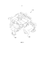
На фиг. 7 в перспективном изображении, в разрезе представлен усовершенствованный насос.In FIG. 7 is a perspective view, in section, of an improved pump.
На фиг. 8 показан, в перспективном изображении, диспенсер, аналогичный показанному на фиг. 7, и альтернативный вариант насоса.In FIG. 8 shows, in a perspective view, a dispenser similar to that shown in FIG. 7, and an alternative pump.
На фиг. 9 насос по фиг. 8 показан в перспективном изображении.In FIG. 9, the pump of FIG. 8 is shown in a perspective view.
На фиг. 10 насос по фиг. 9 показан на виде спереди.In FIG. 10 the pump of FIG. 9 is shown in front view.
На фиг. 11 насос по фиг. 9 показан на виде сбоку.In FIG. 11 the pump of FIG. 9 is shown in side view.
На фиг. 12 насос показан в разрезе плоскостью В-В (см. фиг. 10), чтобы проиллюстрировать рабочий ход.In FIG. 12, the pump is shown in section by the plane BB (see FIG. 10) to illustrate the stroke.
На фиг. 13 насос представлен, в разрезе, аналогичном использованному на фиг. 12, но в стадии обратного хода.In FIG. 13, the pump is shown in section similar to that used in FIG. 12, but in the reverse stage.
На фиг. 14 насос представлен в разрезе плоскостью А-А (см. фиг. 10), чтобы проиллюстрировать траекторию жидкости на входе.In FIG. 14, the pump is shown in section by the plane AA (see FIG. 10) to illustrate the path of the fluid at the inlet.
На фиг. 15 насос представлен в разрезе плоскостью А-А (см. фиг. 10) на промежуточной стадии рабочего хода, при переходе из стадии, в которой изменяется только объем воздушной камеры, в стадию, в которой изменяются объемы воздушной и жидкостной камер.In FIG. 15, the pump is represented in section by the plane AA (see FIG. 10) at an intermediate stage of the stroke, when moving from a stage in which only the volume of the air chamber changes to a stage in which the volumes of the air and liquid chambers change.
На фиг. 16 насос представлен в разрезе плоскостью А-А (см. фиг. 10) на промежуточной стадии рабочего хода, в которой изменяются объемы воздушной и жидкостной камер.In FIG. 16, the pump is represented in section by the plane AA (see FIG. 10) at an intermediate stage of the stroke in which the volumes of the air and liquid chambers change.
На фиг. 17 показана, в разрезе плоскостью Е-Е (см. фиг. 11), выходная жидкостная камера насоса; можно видеть траекторию движения жидкости.In FIG. 17 shows, in section through the plane EE (see FIG. 11), the output liquid chamber of the pump; you can see the trajectory of the fluid.
На фиг. 18 показано, в разрезе плоскостью D-D (см. фиг. 10), выходное сопло насоса; можно видеть каналы для потока пены.In FIG. 18 shows, in section through the plane D-D (see FIG. 10), the pump outlet nozzle; You can see the channels for the flow of foam.
На фиг. 19 показаны, в разрезе плоскостью С-С (см. фиг. 10), пара камер пенообразования насоса и траектория движения воздуха.In FIG. 19 shows, in section by the CC plane (see FIG. 10), a pair of pump foaming chambers and an air trajectory.
На фиг. 20 показан, в перспективном изображении, диспенсер, в который может быть помещен насос.In FIG. 20 shows, in a perspective view, a dispenser in which a pump can be placed.
На фиг. 21 представлен, в разрезе, альтернативный вариант насоса в начале рабочего хода.In FIG. 21 is a cross-sectional view of an alternative pump at the start of a stroke.
На фиг. 22 насос по фиг. 21 представлен, в разрезе, на первой стадии рабочего хода.In FIG. 22, the pump of FIG. 21 is presented, in section, at the first stage of the stroke.
На фиг. 23 насос по фиг. 21 и 22 представлен, в разрезе, в положении перехода от конца первой стадии к промежуточной стадии рабочего хода.In FIG. 23, the pump of FIG. 21 and 22 are presented, in section, in the transition position from the end of the first stage to the intermediate stage of the working stroke.
На фиг. 24 насос по фиг. 21-23 представлен, в разрезе, на промежуточной стадии рабочего хода.In FIG. 24, the pump of FIG. 21-23 is presented, in section, at an intermediate stage of the stroke.
На фиг. 25 насос по фиг. 21-24 представлен, в разрезе, в конце рабочего хода.In FIG. 25 the pump of FIG. 21-24 is presented, in section, at the end of the stroke.
Осуществление изобретенияThe implementation of the invention
На фиг. 1-6 схематично изображен диспенсер 10. Данный диспенсер содержит усовершенствованный пенный насос 12, который представляет собой неаэрозольный насос для использования с контейнером 14 для жидкости, не находящейся под давлением.In FIG. 1-6, a
Насос 12 содержит узел 16 жидкостного насоса и узел 18 воздушного насоса. Узел 16 жидкостного насоса содержит жидкостную камеру 20 и жидкостный поршень 22, который является поршнем с задержкой активации. Узел 18 воздушного насоса содержит воздушную камеру 24 и воздушный поршень 26. Жидкостный поршень 22 и воздушный поршень 26 функционально связаны с активатором 28. У жидкостного поршня 22 имеются активирующая часть 21 и основная часть 23. Активирующая часть 21 жидкостного поршня 22 связана с активатором 28 с возможностью относительного перемещения со скольжением, тогда как воздушный поршень 26 жестко прикреплен к активатору.
У жидкостной камеры 20 имеются вход 30 и выход 32 для жидкости. Эта камера функционально связана с указанным контейнером 14 для жидкости. Между жидкостной камерой 20 и контейнером 14 для жидкости установлен входной жидкостный клапан 34. Жидкостная камера 20 сообщается с пенообразующим блоком 36. Между жидкостной камерой 20 и пенообразующим блоком 36 установлен выходной жидкостный клапан 38.The
У воздушной камеры 24 имеются вход 40 и выход 42 для воздуха. Между воздушной камерой 24 и наружным воздухом установлен входной воздушный клапан 44. Воздушная камера 24 сообщается с пенообразующим блоком 36. Между воздушной камерой 24 и пенообразующим блоком 36 установлен выходной воздушный клапан 46.The
Пенообразующий блок 36 содержит распылительный элемент 48, по одну сторону которого расположена воздушная камера 50 пенообразующего блока, а по другую - камера 52 пенообразования. Воздушная камера 50 пенообразующего блока сообщается с воздушной камерой 24 узла 18 воздушного насоса. Камера 52 пенообразования сообщается с жидкостной камерой 20 узла 16 жидкостного насоса. Воздух проходит под давлением через распылительный элемент 48 в жидкость, находящуюся в камере 52 пенообразования, чтобы образовать пену, которая выходит из пенообразующего блока 36 через выходное сопло 54.Foaming
На фиг. 1-6 иллюстрируются стадии рабочего и обратного ходов насоса. На фиг. 1 насос 12 показан в состоянии покоя. Как это проиллюстрировано на фиг. 2, в начале рабочего хода происходит сжатие воздуха в воздушной камере 24 узла воздушного насоса, при этом выходной воздушный клапан 46 открывается и воздух поступает в воздушную камеру 50 пенообразующего блока. Затем воздух проходит через распылительный элемент 48, встречая сопротивление со стороны жидкости, находящейся в камере 52 пенообразования, и, в меньшей степени, со стороны самого распылительного элемента 48. Давление воздуха повышается до уровня, достаточного, чтобы стала возможной его инфузия (закачивание) в жидкость, находящуюся в камере 52 пенообразования. На начальной стадии рабочего хода активатор движется вдоль активирующей части жидкостного поршня 22, так что жидкостный поршень 22 не движется. Эта стадия является "подготовительной" стадией, на которой производится "подготовка" воздушной камеры до того, как будет приведен в действие жидкостный насос. Когда активатор 28 натолкнется на основную часть 23 жидкостного поршня 22, этот поршень начнет двигаться совместно с воздушным поршнем 26. Давление в жидкостной камере 20 повышается, открывается выходной жидкостный клапан 38, и жидкость начинает перетекать в камеру 52 пенообразования, где в нее будет закачиваться воздух, чтобы создать пену.In FIG. 1-6 illustrate the stages of the working and return strokes of the pump. In FIG. 1, pump 12 is shown at rest. As illustrated in FIG. 2, at the beginning of the working stroke, air is compressed in the
Как показано на фиг. 4, по окончании рабочего хода изменится направление движения активатора 28. В типичном случае это соответствует моменту, когда пользователь прекратит нажимать на активатор. По окончании рабочего хода входной жидкостный клапан 34, выходной жидкостный клапан 38, входной воздушный клапан 44 и выходной воздушный клапан 46 оказываются закрытыми. В начальной стадии обратного хода, проиллюстрированной на фиг. 5, движутся только воздушный поршень 26 и активатор 28, перемещающийся вдоль активирующей части 21 жидкостного поршня 22, тогда как основная часть 23 жидкостного поршня в жидкостной камере 20 неподвижна. Как показано на фиг. 5, при продолжении перемещения активатора 28 вдоль активирующей части 21 жидкостного поршня 22 во время обратного хода открывается входной воздушный клапан 44, так что в воздушную камеру 24 поступает воздух. Как видно из фиг. 6, при дальнейшем перемещении активатора в процессе обратного хода открывается входной жидкостный клапан 34, так что в жидкостную камеру 20 поступает жидкость. На фиг. 1 иллюстрируется завершение обратного хода, т.е. исходное состояние насоса 12, в котором входной жидкостный клапан 34, выходной жидкостный клапан 38, входной воздушный клапан 44 и выходной воздушный клапан 46 закрыты.As shown in FIG. 4, at the end of the stroke, the direction of movement of the
Следует отметить, что, как это известно специалистам, насос должен быть также снабжен не изображенными на схематичных видах по фиг. 1-6 средствами, обеспечивающими удерживание его подвижных компонентов в состоянии покоя.It should be noted that, as is known to those skilled in the art, the pump should also be provided with those not shown in diagrammatic form in FIG. 1-6 means ensuring the retention of its moving components at rest.
На фиг. 7-20 представлен альтернативный вариант усовершенствованного пенного насоса 112, который является неаэрозольным насосом для использования совместно с контейнером 114 для жидкости, не находящейся под давлением. Для большей наглядности фиг. 10-20, по возможности, упрощены, так что некоторые жестко соединенные между собой компоненты могут быть изображены в виде единой детали.In FIG. 7-20 show an alternative embodiment of an
Насос 112 содержит узел 116 жидкостного насоса и узел 118 воздушного насоса (см., например, фиг. 13). Узел 116 жидкостного насоса содержит жидкостную камеру 120 и жидкостный поршень 122, который является поршнем с задержкой активации. Узел 118 воздушного насоса содержит воздушную камеру 124 и воздушный поршень 126. Воздушная камера 124 окружает жидкостную камеру 120 и расположена соосно с ней. Жидкостный поршень 122 и воздушный поршень 126 функционально связаны, так что активирование воздушного поршня 126 приводит к активированию жидкостного поршня. Воздушный поршень 126 содержит часть 121 для связи с жидкостным поршнем, которая при своем перемещении со скольжением может сопрягаться с жидкостным поршнем 122. На начальной стадии рабочего хода жидкостный поршень 122, в отличие от воздушного поршня 126, не перемещается, так что объем жидкостной камеры 120 остается неизменным, тогда как объем воздушной камеры 124 начинает уменьшаться. Это соответствует "подготовительной" стадии, на которой производится "подготовка" воздушной камеры до того, как будет приведен в действие жидкостный насос. В переходной точке часть 121 воздушного поршня 126 упирается в жидкостный поршень 122; после чего объемы воздушной камеры 124 и жидкостной камеры 120 будут уменьшаться одновременно.
Как показано на фиг. 14-16, у жидкостной камеры 120 имеются вход 130 и выход 132 для жидкости. Эта камера функционально связана с упомянутым контейнером 114 (см. фиг. 7). Между жидкостной камерой 120 и контейнером 114 для жидкости установлен входной жидкостный клапан 134. Жидкостная камера 120 сообщается с пенообразующим блоком 136. Между жидкостной камерой 120 и пенообразующим блоком 136 установлен выходной жидкостный клапан 138. И входной клапан 134, и выходной клапан 138 являются обратными шариковыми клапанами. Должно быть понятно, что клапаны данного типа приведены только в качестве примера и что вместо них могут использоваться и другие клапаны.As shown in FIG. 14-16, the
У воздушной камеры 124 имеются вход 140 и выход 142 для воздуха (см. фиг. 12). Между воздушной камерой 124 и наружным воздухом установлен входной воздушный клапан 144. Воздушная камера 124 сообщается с пенообразующим блоком 136. В отличие от варианта, описанного со ссылками на фиг. 1-6, насос 112 не содержит выходного воздушного клапана. При обратном ходе насоса усилие, требуемое, чтобы открыть входной воздушный клапан 144, меньше, чем усилие, требуемое, чтобы всосать пену обратно через распылительный элемент 148, и именно поэтому выходной воздушный клапан в данном варианте не используется. Однако, по желанию, насос 112 может содержать и выходной воздушный клапан.The
Пенообразующий блок 136 содержит распылительный элемент 148, по одну сторону которого расположена воздушная камера 150 пенообразующего блока, а по другую - камера 152 пенообразования. Воздушная камера 150 пенообразующего блока сообщается с воздушной камерой 124 узла 118 воздушного насоса. Камера 152 пенообразования сообщается с жидкостной камерой 120 узла 116 жидкостного насоса. Воздух проходит под давлением через распылительный элемент 148 в жидкость, находящуюся в камере 152 пенообразования, чтобы образовать пену. Пена выходит из пенообразующего блока 136 и проходит через выходной канал 166 для пены (см. фиг. 19) в объединенный проточный канал 168. Данный канал, который задается поршнем 169 с задержкой активации в составе выходного сопла, сообщается с выходным соплом 154. Выходное сопло 154 снабжено выходным сопловым клапаном 155. Объем объединенного проточного канала 168 зависит от положения поршня выходного сопла, как это легко видеть из фиг. 14-16. В результате пена, формируемая в пенообразующем блоке 136, проходит через выходные каналы 166 для пены в объединенный проточный канал 168 и выходит из насоса 112 через выходное сопло 154.
На фиг. 8-19 иллюстрируются части насоса и стадии его рабочего и обратного ходов. На фиг. 14 показана траектория движения жидкости во время обратного хода, когда жидкость всасывается в жидкостную камеру 120 через входной канал 158 для жидкости. Возвратная пружина 161 отжимает воздушный поршень 126 и жидкостный поршень 122. Когда начинается рабочий ход, происходит сжатие воздуха в воздушной камере 124 узла воздушного насоса, и часть 121 воздушного поршня перемещается относительно жидкостного поршня 122. Однако объем жидкостной камеры 120 не изменяется до достижения точки перехода (см. фиг. 15). При продолжении рабочего хода насоса жидкость из жидкостной камеры 120 вытесняется через выход 132 для жидкости, проходя через открытый выходной жидкостный клапан 138. Конец рабочего хода иллюстрируется фиг. 16. Жидкость проходит от выхода 132 для жидкости в выходной канал 160 для жидкости и в камеру 152 пенообразования. Как показано на фиг. 17, в данном варианте имеются два выходных канала 160 для жидкости и две камеры 152 пенообразования. Эти выходные каналы и камеры пенообразования имеют одинаковые объемы. Две камеры 152 пенообразования соответствуют первому пенообразующему блоку и второму пенообразующему блоку.In FIG. 8-19 illustrate the parts of the pump and the stages of its working and return strokes. In FIG. 14 shows the trajectory of the fluid during the return stroke when the fluid is sucked into the
Наличие двух камер 152 пенообразования обеспечивает ряд преимуществ. В частности, такое выполнение приводит к увеличению эффективной длительности процесса закачивания воздуха в жидкость. Далее, использование двух камер 152 пенообразования позволяет удвоить объем воздуха, нагнетаемого при уменьшенном перемещении поршня. Предлагаемый вариант с двумя камерами 152 пенообразования обеспечивает лучше сбалансированную конструкцию, чем вариант с центральным активатором или точкой давления для воздействия на воздушный поршень 126 и жидкостный поршень 122. Кроме того, предлагаемая конструкция с двумя камерами 152 пенообразования является более компактной, чем это было бы в случае использования одной большой камеры пенообразования.The presence of two
Траектория 162 движения входящего воздуха показана на фиг. 12 и 13. При обратном ходе в воздушной камере 124 создается вакуум, обратный входной воздушный клапан 144 открывается, и воздух всасывается в воздушную камеру, как это показано на фиг. 13. На фиг. 12 показана также траектория движения воздуха на выходе. В начале рабочего хода воздушный поршень 126 перемещается внутрь и соответственно уменьшает объем воздушной камеры 124, вытесняя воздух из этой камеры в выходной канал 164 для воздуха (см. фиг. 17) и в воздушную камеру 150 пенообразующего блока, показанную на фиг. 12, 13 и 19.Incoming air path 162 is shown in FIG. 12 and 13. During the return stroke, a vacuum is created in the
На фиг. 19 показан пенообразующий блок; видны его распылительный элемент 148, воздушная камера 150 пенообразующего блока и камера 152 пенообразования. Пена из каждой камеры 152 пенообразования проходит к выходному соплу 154 по выходному каналу 166 и затем через объединенный проточный канал 168, показанный на фиг. 18.In FIG. 19 shows a foaming unit; its
Как показано на фиг. 7. 8 и 20, насос 112 может быть установлен в диспенсер 170. У диспенсера имеется нажимная кнопка 172, которая воздействует на жидкостный поршень 122, скомбинированный с воздушным поршнем 126.As shown in FIG. 7. 8 and 20, the
На фиг. 21-25 представлен еще один вариант насоса 212. Насос 212 содержит узел 216 жидкостного насоса и узел 218 воздушного насоса. Узел 216 жидкостного насоса содержит жидкостную камеру 220 и жидкостный поршень 222. Жидкостный поршень 222 является поршнем с задержкой активации. Узел 218 воздушного насоса содержит воздушную камеру 224 и воздушный поршень 226. Жидкостный поршень 222 и воздушный поршень 226 функционально связаны с активатором (не изображен). Жидкостный поршень 222 содержит активирующую часть 221 и основную часть 223. Воздушный поршень 226 прикреплен к активирующей части 221 жидкостного поршня 222 с задержкой активации.In FIG. 21-25, another embodiment of
У жидкостной камеры 220 имеются вход 230 и выход 232 для жидкости. Эта камера функционально связана с неизображенным контейнером для жидкости, не находящейся под давлением. Между жидкостной камерой 220 и контейнером для жидкости установлен входной жидкостный клапан 234. Жидкостная камера 220 сообщается со смесительной камерой 236. Между жидкостной камерой 220 и смесительной камерой 236 установлен выходной жидкостный клапан 238.The
У воздушной камеры 224 имеются вход 240 и выход 242 для воздуха. Воздушная камера 224 сообщается со смесительной камерой 236. В смесительной камере 236 смешиваются воздух из воздушной камеры 224 и жидкость из жидкостной камеры 220. Затем смесь воздуха и жидкости проходит через пенообразователь 248 в выходное сопло 254. Пенообразователем 248 может служить тонкая сетка, газовая ткань, пена, губка или другой пригодный пористый материал. Смесь воздуха и жидкости проходит под давлением через пенообразователь 248, чтобы создать пену. Таким образом, в этом варианте пенообразующий блок содержит смесительную камеру 236 и пенообразователь 248.
На фиг. 21-25 иллюстрируются стадии рабочего и обратного ходов насоса. На фиг. 21 насос 212 показан в состоянии покоя. Как видно из фиг. 22, в начале рабочего хода происходит сжатие воздуха в воздушной камере 224 узла воздушного насоса, так что воздух поступает в смесительную камеру 236. В результате повышения давления воздуха воздух и жидкость проходят под давлением через пенообразующий блок 248. На начальной стадии рабочего хода активирующая часть 221 жидкостного поршня 222 движется относительно основной части 223, а объем жидкостной камеры 220 остается неизменным, как это показано на фиг. 22 и 23. Эта стадия является "подготовительной" стадией, на которой производится "подготовка" воздушной камеры до того, как будет приведен в действие жидкостный насос. Когда активирующая часть 221 вступит в сопряжение с основной частью 223 жидкостного поршня 222, этот поршень 222 начинает двигаться вместе с воздушным поршнем 226. Давление в жидкостной камере 220 повышается, открывается выходной жидкостный клапан 238, и жидкость поступает в смесительную камеру 236, как это проиллюстрировано на фиг. 24. В конце рабочего хода (см. фиг. 25) направление движения воздушного поршня 226 и жидкостного поршня 222 изменится. В типичном случае это соответствует моменту, когда пользователь прекратит нажимать на активатор или нажимную кнопку (не изображены). По окончании рабочего хода входной жидкостный клапан 234, выходной жидкостный клапан 238 и входной воздушный клапан 244 оказываются закрытыми.In FIG. 21-25 illustrate the stages of the working and return strokes of the pump. In FIG. 21, pump 212 is shown at rest. As can be seen from FIG. 22, at the beginning of the working stroke, air is compressed in the
Из анализа уровня техники должно быть ясно, что для достижения максимальной эффективности закачивания (инфузии) воздуха в жидкость с получением в насосе высококачественной пены требуется преодолеть фундаментальную проблему, состоящую в том, что воздух является сжимаемым, а жидкости нет.From the analysis of the prior art, it should be clear that in order to achieve maximum efficiency of pumping (infusion) of air into the liquid to obtain high-quality foam in the pump, it is necessary to overcome the fundamental problem that the air is compressible and there is no liquid.
Описанные насосы по изобретению сначала создают достаточное давление в воздушной части насоса, так что, когда начинается нагнетание жидкости, немедленно может начаться инфузия в нее воздуха. В результате процесс инфузии будет интенсифицирован, так что качество пены, выдаваемой насосом, будет оптимизировано.The described pumps of the invention first create sufficient pressure in the air part of the pump, so that when fluid injection begins, infusion of air into it can immediately begin. As a result, the infusion process will be intensified, so that the quality of the foam dispensed by the pump will be optimized.
Описанный пенный насос создает внутреннее давление воздуха до того, как начнется прокачка одновременно воздуха и жидкости. Другими словами, процесс выдачи пены начинается с подачи воздуха в течение части рабочего хода, после чего следует подача одновременно воздуха и жидкости. Повышение давления воздуха способствует более эффективной инфузии воздуха в жидкость, что дает более высокое качество пены, выдаваемой пользователю.The described foam pump creates internal air pressure before pumping simultaneously of air and liquid. In other words, the foam dispensing process begins with the supply of air during part of the stroke, followed by the supply of both air and liquid. The increase in air pressure contributes to a more efficient infusion of air into the liquid, which gives a higher quality foam issued to the user.
Предложенные решения относятся к пенному насосу, причем были представлены различные варианты и аспекты изобретения. При этом представленные описание и чертежи имеют иллюстративный характер и не должны рассматриваться как вносящие какие-либо ограничения в объем изобретения. Многочисленные конкретные детали приведены, чтобы обеспечить ясное понимание различных вариантов изобретения. Вместе с тем, в определенных случаях хорошо известные или очевидные детали были опущены, чтобы яснее описать различные варианты изобретения.The proposed solutions relate to a foam pump, and various options and aspects of the invention were presented. Moreover, the presented description and drawings are illustrative and should not be construed as introducing any limitations to the scope of the invention. Numerous specific details are provided to provide a clear understanding of the various embodiments of the invention. However, in certain cases, well-known or obvious details have been omitted in order to more clearly describe the various embodiments of the invention.
Используемые в контексте изобретения термины "содержит" и "содержащий" должны интерпретироваться как инклюзивные, а не как имеющие исчерпывающий смысл. Более конкретно, использование в описании и формуле терминов "содержит", "содержащий" и производных от них терминов означает наличие соответствующих признаков, операций или компонентов. При этом данные термины не должны интерпретироваться как исключающие наличие других признаков, операций или компонентов.Used in the context of the invention, the terms “contains” and “comprising” should be interpreted as inclusive, and not as having an exhaustive meaning. More specifically, the use of the terms “comprises”, “comprising” and their derivative terms in the description and formula means the presence of appropriate features, operations or components. However, these terms should not be interpreted as excluding the presence of other signs, operations or components.
Термин "функционально связаны" в контексте изобретения означает, что два соответствующих элемента соединены непосредственно или через другие элементы.The term "functionally connected" in the context of the invention means that two corresponding elements are connected directly or through other elements.
Термин "по существу" означает полное или почти полное проявление действия, характеристики, свойства, состояния, структуры, объекта или результата. Например, выражение "по существу, окруженный объект" означает, что объект окружен полностью или почти полностью. Допустимая степень отклонения от полного проявления может в некоторых случаях зависеть от конкретного контекста. Однако в общем случае близость к полному проявлению должна быть такой, чтобы достигаемый результат был таким же, как и в случае полного (абсолютного) проявления. Использование термина "по существу" в равной степени допустимо и применительно к полному или почти полному отсутствию действия, характеристики, свойства, состояния, структуры, объекта или результата.The term "essentially" means the full or almost complete manifestation of an action, characteristic, property, state, structure, object or result. For example, the expression "essentially surrounded by an object" means that the object is surrounded completely or almost completely. The permissible degree of deviation from the full manifestation may in some cases depend on the specific context. However, in the general case, the proximity to the full manifestation should be such that the achieved result is the same as in the case of the full (absolute) manifestation. The use of the term “essentially” is equally acceptable and applies to the complete or almost complete absence of an action, characteristic, property, state, structure, object or result.
Claims (25)
Applications Claiming Priority (3)
| Application Number | Priority Date | Filing Date | Title |
|---|---|---|---|
| US201461992101P | 2014-05-12 | 2014-05-12 | |
| US61/992,101 | 2014-05-12 | ||
| PCT/CA2015/050471 WO2015172257A1 (en) | 2014-05-12 | 2015-05-12 | Improved foam pump |
Related Child Applications (1)
| Application Number | Title | Priority Date | Filing Date |
|---|---|---|---|
| RU2018143473A Division RU2752311C2 (en) | 2014-05-12 | 2015-05-12 | Improved foam pump |
Publications (3)
| Publication Number | Publication Date |
|---|---|
| RU2016147546A RU2016147546A (en) | 2018-06-14 |
| RU2016147546A3 RU2016147546A3 (en) | 2018-10-09 |
| RU2674873C2 true RU2674873C2 (en) | 2018-12-13 |
Family
ID=54366731
Family Applications (2)
| Application Number | Title | Priority Date | Filing Date |
|---|---|---|---|
| RU2018143473A RU2752311C2 (en) | 2014-05-12 | 2015-05-12 | Improved foam pump |
| RU2016147546A RU2674873C2 (en) | 2014-05-12 | 2015-05-12 | Improved foam pump |
Family Applications Before (1)
| Application Number | Title | Priority Date | Filing Date |
|---|---|---|---|
| RU2018143473A RU2752311C2 (en) | 2014-05-12 | 2015-05-12 | Improved foam pump |
Country Status (12)
| Country | Link |
|---|---|
| US (1) | US9718069B2 (en) |
| EP (1) | EP3142962B1 (en) |
| JP (1) | JP6789826B2 (en) |
| CN (1) | CN106458566B (en) |
| AU (1) | AU2015258718C1 (en) |
| BR (1) | BR112016025523B1 (en) |
| CA (1) | CA2944219C (en) |
| MX (1) | MX2016013357A (en) |
| PL (1) | PL3142962T3 (en) |
| RU (2) | RU2752311C2 (en) |
| SG (1) | SG11201608811WA (en) |
| WO (1) | WO2015172257A1 (en) |
Cited By (1)
| Publication number | Priority date | Publication date | Assignee | Title |
|---|---|---|---|---|
| RU2781634C1 (en) * | 2019-10-29 | 2022-10-17 | Хюбнер Гмбх Унд Ко. Кг | Foam pump |
Families Citing this family (17)
| Publication number | Priority date | Publication date | Assignee | Title |
|---|---|---|---|---|
| US20140054323A1 (en) | 2012-08-23 | 2014-02-27 | Gojo Industries, Inc. | Horizontal pumps, refill units and foam dispensers with integral air compressors |
| US9579613B2 (en) | 2013-12-16 | 2017-02-28 | Gojo Industries, Inc. | Foam-at-a-distance systems, foam generators and refill units |
| US9737177B2 (en) * | 2014-05-20 | 2017-08-22 | Gojo Industries, Inc. | Two-part fluid delivery systems |
| US9757754B2 (en) * | 2015-09-09 | 2017-09-12 | The Procter & Gamble Company | Dispensers for dispensing microcapsules |
| CA3003178C (en) * | 2015-11-12 | 2023-12-12 | Gojo Industries, Inc. | Sequentially activated multi-diaphragm foam pump |
| US10065199B2 (en) * | 2015-11-13 | 2018-09-04 | Gojo Industries, Inc. | Foaming cartridge |
| WO2017087741A1 (en) | 2015-11-18 | 2017-05-26 | Gojo Industries, Inc. | A refill unit for a foam dispenser |
| US10080467B2 (en) | 2015-11-20 | 2018-09-25 | Gojo Industries, Inc. | Foam dispensing systems, pumps and refill units having high air to liquid ratios |
| US10080468B2 (en) | 2015-12-04 | 2018-09-25 | Gojo Industries, Inc. | Sequentially activated multi-diaphragm foam pumps, refill units and dispenser systems |
| US10441115B2 (en) | 2016-02-11 | 2019-10-15 | Gojo Industries, Inc. | High quality non-aerosol hand sanitizing foam |
| US10143339B2 (en) | 2016-04-06 | 2018-12-04 | Gojo Industries, Inc. | Sequentially activated multi-diaphragm foam pumps, refill units and dispenser systems |
| US10912426B2 (en) | 2016-04-06 | 2021-02-09 | Gojo Industries, Inc. | Sequentially activated multi-diaphragm foam pumps, refill units and dispenser systems |
| CN106073589A (en) * | 2016-08-09 | 2016-11-09 | 江门市爱威特电器有限公司 | A kind of automatic soap dispenser |
| CA2942640C (en) | 2016-09-21 | 2023-06-27 | Op-Hygiene Ip Gmbh | Pump for under counter dispensing system |
| JP6904568B2 (en) * | 2017-10-24 | 2021-07-21 | 株式会社タカギ | Fluid discharge tool |
| EP3773101B1 (en) * | 2018-04-06 | 2023-10-18 | Gojo Industries, Inc. | Foam-at-a-distance dispensing systems |
| DE102019123200B4 (en) * | 2019-08-29 | 2021-12-30 | Marco Systemanalyse Und Entwicklung Gmbh | DEVICE AND METHOD FOR SUPPLYING A LIQUID MEDIUM |
Citations (3)
| Publication number | Priority date | Publication date | Assignee | Title |
|---|---|---|---|---|
| CA2669519A1 (en) * | 2008-06-20 | 2009-12-20 | Gojo Industries, Inc. | Two-stroke foam pump |
| US20120141309A1 (en) * | 2010-12-02 | 2012-06-07 | Gojo Industries, Inc. | Pump with side inlet valve for improved functioning in an inverted container |
| RU2504323C1 (en) * | 2010-04-22 | 2014-01-20 | Ска Хайджин Продактс Аб | Dispensing device and container for liquid |
Family Cites Families (78)
| Publication number | Priority date | Publication date | Assignee | Title |
|---|---|---|---|---|
| US2494827A (en) | 1945-06-01 | 1950-01-17 | Hall Lab Inc | Abrasive detergent compositions |
| US3422993A (en) | 1967-07-26 | 1969-01-21 | Johnson & Son Inc S C | Foam dispensing device and package |
| US3709437A (en) | 1968-09-23 | 1973-01-09 | Hershel Earl Wright | Method and device for producing foam |
| BE758980A (en) | 1970-01-21 | 1971-04-30 | Zyma Sa | METERING VALVE |
| US4019657A (en) | 1975-03-03 | 1977-04-26 | Spitzer Joseph G | Aerosol containers for foaming and delivering aerosols |
| US4022351A (en) | 1975-04-03 | 1977-05-10 | Hershel Earl Wright | Foam dispenser |
| US3985271A (en) | 1975-06-06 | 1976-10-12 | Glasrock Products, Inc. | Foam generating and dispensing device |
| US4051877A (en) | 1975-10-24 | 1977-10-04 | Nasa | Gas compression apparatus |
| US4155870A (en) | 1976-04-19 | 1979-05-22 | Minnesota Mining And Manufacturing Company | Skin cleaning compositions containing water-insoluble glass bubbles |
| US4238056A (en) | 1978-03-06 | 1980-12-09 | Towlsaver, Inc. | Soap dispenser having a pivotable dispensing lever and a rotatable flow valve |
| CA1190841A (en) | 1981-01-21 | 1985-07-23 | Cecil L. Phillips | Composites and methods for providing metal clad articles and articles produced thereby |
| US4621749A (en) | 1984-02-21 | 1986-11-11 | Go-Jo Industries | Dispensing apparatus |
| DE3668426D1 (en) * | 1985-01-28 | 1990-03-01 | Earl Wright Co | FOAM GENERATOR. |
| US4639367A (en) | 1985-03-18 | 1987-01-27 | Product Resources International, Inc. | Aerosol foam |
| US4615467A (en) | 1985-07-24 | 1986-10-07 | Calmar, Inc. | Liquid foam dispenser |
| US4957218A (en) | 1986-07-28 | 1990-09-18 | Ballard Medical Products | Foamer and method |
| CH676456A5 (en) | 1988-04-05 | 1991-01-31 | Supermatic Kunststoff Ag | |
| US4978036A (en) | 1988-11-15 | 1990-12-18 | Koller Enterprises, Inc. | Dispensing valve |
| DE3911510A1 (en) | 1989-04-08 | 1990-10-11 | Pfeiffer Erich Gmbh & Co Kg | DISCHARGE DEVICE FOR MEDIA |
| EP0449774B1 (en) | 1990-03-24 | 1993-11-03 | George Edgar Callahan | Dispenser for foaming a liquid product |
| FR2662672B1 (en) * | 1990-05-31 | 1992-08-21 | Aerosols & Bouchage | MIXTURE DISPENSER. |
| US5238155A (en) | 1991-02-11 | 1993-08-24 | Jack W. Kaufman | Foam generating device |
| US5348189A (en) | 1991-04-10 | 1994-09-20 | Bespak Plc | Air purge pump dispenser |
| FR2676010B1 (en) | 1991-04-30 | 1993-08-13 | Oreal | DEVICE FOR DISPENSING FOAM, AND PUSH-BUTTON FOR SUCH A DEVICE. |
| US5174476A (en) | 1991-05-06 | 1992-12-29 | Steiner Company, Inc. | Liquid soap dispensing system |
| US5232632A (en) | 1991-05-09 | 1993-08-03 | The Procter & Gamble Company | Foam liquid hard surface detergent composition |
| US5165577A (en) | 1991-05-20 | 1992-11-24 | Heiner Ophardt | Disposable plastic liquid pump |
| US5279755A (en) | 1991-09-16 | 1994-01-18 | The Clorox Company | Thickening aqueous abrasive cleaner with improved colloidal stability |
| US5248066A (en) | 1992-03-27 | 1993-09-28 | Ecolab Inc. | Liquid dispenser with collapsible reservoir holder |
| US5339988A (en) | 1992-10-19 | 1994-08-23 | Ballard Medical Products | Disposable tray sump foamer, assembly and methods |
| FR2698102B1 (en) | 1992-11-18 | 1995-02-03 | Health Business Dev | Composition intended for washing the skin or mucous membranes. |
| GB9224563D0 (en) | 1992-11-24 | 1993-01-13 | Unilever Plc | Cosmetic composition |
| US5425404A (en) | 1993-04-20 | 1995-06-20 | Minnesota Mining And Manufacturing Company | Gravity feed fluid dispensing system |
| US5445288A (en) * | 1994-04-05 | 1995-08-29 | Sprintvest Corporation Nv | Liquid dispenser for dispensing foam |
| DE4429454A1 (en) | 1994-08-19 | 1996-02-22 | Katz Otto | Spray pump using air=atomised fluids |
| US5570840A (en) * | 1994-10-14 | 1996-11-05 | Fourth And Long, Inc. | Hand-held spraying apparatus |
| ES2156189T3 (en) | 1995-09-29 | 2001-06-16 | Procter & Gamble | METHOD TO TREAT TEXTILE FABRICS WITH FOAM. |
| CA2202224C (en) | 1996-04-18 | 2001-01-23 | Mark S. Wdowik | Shaving compositions containing particulate additives |
| EP0829259A1 (en) | 1996-09-04 | 1998-03-18 | Warner-Lambert Company | Foam/gel with microbeads and/or fine particles |
| US5984146A (en) | 1996-09-27 | 1999-11-16 | Kaufman; John G. | Dispenser having foamed output |
| US5804540A (en) | 1997-01-08 | 1998-09-08 | Lever Brothers Company, Division Of Conopco, Inc. | Personal wash liquid composition comprising low viscosity oils pre-thickened by non-antifoaming hydrophobic polymers |
| CA2244591A1 (en) | 1997-08-19 | 1999-02-19 | Unilever Plc | Topical cleansing composition |
| US5985294A (en) | 1997-11-05 | 1999-11-16 | The Procter & Gamble Company | Personal care compositions |
| US5985295A (en) | 1997-11-05 | 1999-11-16 | The Procter & Gamble Company | Personal care compositions |
| GB2335005A (en) | 1998-02-18 | 1999-09-08 | David Kennedy | Method and apparatus for dispensing product in mousse form |
| US6082586A (en) | 1998-03-30 | 2000-07-04 | Deb Ip Limited | Liquid dispenser for dispensing foam |
| BR9910734A (en) | 1998-05-28 | 2001-02-13 | Colgate Palmolive Co | Composition composed of a clear, clean, aqueous phase and processes to clean and condition the skin or hair concomitantly, and to prepare a composition |
| US6271275B1 (en) | 1998-08-17 | 2001-08-07 | Sealed Air Corp. (Us) | Method and apparatus for producing polyurethane foam |
| US6394316B1 (en) | 1998-08-28 | 2002-05-28 | Warren S. Daansen | Bubble pump for dispensing particulate-ladened fluid |
| US6276613B1 (en) * | 1999-02-22 | 2001-08-21 | Alto Us, Inc. | Chemical foaming system for floor cleaning machine |
| US6264964B1 (en) | 1999-04-14 | 2001-07-24 | Conopco, Inc. | Foaming cosmetic products |
| US6321943B1 (en) | 1999-10-09 | 2001-11-27 | Gent-I-Kleen Products, Inc. | Soap dispenser for soap of different viscosity |
| GB9925439D0 (en) | 1999-10-27 | 1999-12-29 | Unilever Plc | Hair treatment compositions |
| WO2001096708A1 (en) | 2000-06-12 | 2001-12-20 | Steven Craig Myers | Reciprocating windmill pumping system |
| ES2184725T3 (en) | 2000-07-13 | 2003-04-16 | Oreal | COSMETIC COMPOSITION OF FOAM CLEANING. |
| DE10113054A1 (en) | 2001-03-15 | 2002-09-26 | Beiersdorf Ag | Self-foaming product used for skin care contains an emulsifier system, a lipid phase, gas, inorganic thickener, organic hydrocolloid and solid body |
| US6660282B2 (en) | 2001-05-11 | 2003-12-09 | Unilever Home & Personal Care Usa, Division Of Conopco, Inc. | Self foaming cosmetic product |
| GB0112286D0 (en) | 2001-05-19 | 2001-07-11 | Sun Chemical Group B V | Bio-active de-inking or cleaning foam |
| DE10153077A1 (en) | 2001-10-30 | 2003-05-22 | Degussa | Use of granules based on pyrogenic silicon dioxide in cosmetic compositions |
| GB0208806D0 (en) | 2002-04-17 | 2002-05-29 | Rieke Corp | Dispenser pumps |
| US6913251B2 (en) | 2003-02-12 | 2005-07-05 | William B. Kerfoot | Deep well sparging |
| CA2461430A1 (en) | 2004-03-19 | 2005-09-19 | Hygiene-Technik Inc. | Foam and grit dispenser |
| EA009671B1 (en) * | 2004-05-07 | 2008-02-28 | Деб Ай-Пи Лимитед | Foamed cleanser with suspended particles, a method of producing same, and a dispenser therefore |
| CN2931844Y (en) * | 2006-01-13 | 2007-08-08 | 林添大 | Improved foam pump |
| NL1031092C2 (en) * | 2006-02-07 | 2007-08-08 | Airspray Nv | Self-cleaning foam dispenser. |
| US20070278247A1 (en) * | 2006-05-30 | 2007-12-06 | Stewart Banks | Foam dispenser and method of making foam from more than one liquid |
| US8544698B2 (en) | 2007-03-26 | 2013-10-01 | Gojo Industries, Inc. | Foam soap dispenser with stationary dispensing tube |
| US8579159B2 (en) * | 2008-01-18 | 2013-11-12 | Gojo Industries, Inc. | Squeeze action foam pump |
| US20090184134A1 (en) * | 2008-01-18 | 2009-07-23 | Ciavarella Nick E | Foam dispenser with liquid tube pump refill unit |
| US8047403B2 (en) * | 2008-02-08 | 2011-11-01 | Gojo Industries, Inc. | Bifurcated stem foam pump |
| US7861895B2 (en) * | 2008-03-18 | 2011-01-04 | Gojo Industries, Inc. | High velocity foam pump |
| CA2667158A1 (en) * | 2008-05-29 | 2009-11-29 | Gojo Industries, Inc. | Pull actuated foam pump |
| US8733596B2 (en) * | 2009-02-27 | 2014-05-27 | Gotohti.Com Inc. | Ozone foam dispenser |
| GB201018005D0 (en) * | 2010-10-26 | 2010-12-08 | Reckitt Benckiser Inc | Dispenser for a foaming liquid composition |
| US8662355B2 (en) * | 2011-08-11 | 2014-03-04 | Gojo Industries, Inc. | Split body pumps for foam dispensers and refill units |
| US20140054323A1 (en) * | 2012-08-23 | 2014-02-27 | Gojo Industries, Inc. | Horizontal pumps, refill units and foam dispensers with integral air compressors |
| US9038862B2 (en) * | 2013-01-23 | 2015-05-26 | Gojo Industries, Inc. | Pumps with container vents |
| US8955718B2 (en) * | 2012-10-31 | 2015-02-17 | Gojo Industries, Inc. | Foam pumps with lost motion and adjustable output foam pumps |
-
2015
- 2015-05-12 CA CA2944219A patent/CA2944219C/en active Active
- 2015-05-12 US US14/710,345 patent/US9718069B2/en active Active
- 2015-05-12 BR BR112016025523-2A patent/BR112016025523B1/en active IP Right Grant
- 2015-05-12 RU RU2018143473A patent/RU2752311C2/en active
- 2015-05-12 CN CN201580024696.4A patent/CN106458566B/en active Active
- 2015-05-12 WO PCT/CA2015/050471 patent/WO2015172257A1/en active Application Filing
- 2015-05-12 MX MX2016013357A patent/MX2016013357A/en unknown
- 2015-05-12 JP JP2016567805A patent/JP6789826B2/en active Active
- 2015-05-12 AU AU2015258718A patent/AU2015258718C1/en active Active
- 2015-05-12 RU RU2016147546A patent/RU2674873C2/en active
- 2015-05-12 EP EP15793387.0A patent/EP3142962B1/en active Active
- 2015-05-12 SG SG11201608811WA patent/SG11201608811WA/en unknown
- 2015-05-12 PL PL15793387.0T patent/PL3142962T3/en unknown
Patent Citations (3)
| Publication number | Priority date | Publication date | Assignee | Title |
|---|---|---|---|---|
| CA2669519A1 (en) * | 2008-06-20 | 2009-12-20 | Gojo Industries, Inc. | Two-stroke foam pump |
| RU2504323C1 (en) * | 2010-04-22 | 2014-01-20 | Ска Хайджин Продактс Аб | Dispensing device and container for liquid |
| US20120141309A1 (en) * | 2010-12-02 | 2012-06-07 | Gojo Industries, Inc. | Pump with side inlet valve for improved functioning in an inverted container |
Cited By (2)
| Publication number | Priority date | Publication date | Assignee | Title |
|---|---|---|---|---|
| RU2791010C1 (en) * | 2019-08-12 | 2023-03-01 | Сяовэй (Шанхай) Байотекнолоджи Ко., Лтд | Integrated diaphragm pump |
| RU2781634C1 (en) * | 2019-10-29 | 2022-10-17 | Хюбнер Гмбх Унд Ко. Кг | Foam pump |
Also Published As
| Publication number | Publication date |
|---|---|
| RU2018143473A3 (en) | 2021-03-01 |
| EP3142962B1 (en) | 2023-09-20 |
| SG11201608811WA (en) | 2016-11-29 |
| WO2015172257A1 (en) | 2015-11-19 |
| CN106458566B (en) | 2019-03-08 |
| PL3142962T3 (en) | 2024-05-20 |
| AU2015258718C1 (en) | 2020-01-16 |
| AU2015258718B2 (en) | 2019-10-10 |
| BR112016025523A2 (en) | 2017-08-15 |
| US9718069B2 (en) | 2017-08-01 |
| EP3142962A1 (en) | 2017-03-22 |
| NZ724781A (en) | 2020-09-25 |
| CN106458566A (en) | 2017-02-22 |
| AU2015258718A1 (en) | 2016-11-24 |
| US20150320266A1 (en) | 2015-11-12 |
| EP3142962A4 (en) | 2017-12-13 |
| RU2018143473A (en) | 2019-03-22 |
| RU2016147546A3 (en) | 2018-10-09 |
| CA2944219C (en) | 2020-09-15 |
| MX2016013357A (en) | 2017-02-09 |
| JP6789826B2 (en) | 2020-11-25 |
| BR112016025523B1 (en) | 2022-03-22 |
| RU2752311C2 (en) | 2021-07-26 |
| JP2017524390A (en) | 2017-08-31 |
| CA2944219A1 (en) | 2015-11-19 |
| RU2016147546A (en) | 2018-06-14 |
Similar Documents
| Publication | Publication Date | Title |
|---|---|---|
| RU2674873C2 (en) | Improved foam pump | |
| US20020139816A1 (en) | Dosing pump for liquid dispensers | |
| EP3851202B1 (en) | Two stage foam pump and method of producing foam | |
| US10376917B2 (en) | Retractable nozzle for dosing or dispensing high viscosity materials | |
| US11305306B2 (en) | Dual pump hand cleaner foam dispenser | |
| EP3773100B1 (en) | Foam pumps, refill units and dispensers with differential bore suck-back mechanism | |
| JP7337054B2 (en) | Dual inlet valve for improved pump efficiency | |
| NZ724781B2 (en) | Improved foam pump | |
| CA3018299A1 (en) | Two stage foam pump and method of producing foam |