RU2674098C1 - Modular engine, such as jet engine, with speed reduction gear - Google Patents
Modular engine, such as jet engine, with speed reduction gear Download PDFInfo
- Publication number
- RU2674098C1 RU2674098C1 RU2016119153A RU2016119153A RU2674098C1 RU 2674098 C1 RU2674098 C1 RU 2674098C1 RU 2016119153 A RU2016119153 A RU 2016119153A RU 2016119153 A RU2016119153 A RU 2016119153A RU 2674098 C1 RU2674098 C1 RU 2674098C1
- Authority
- RU
- Russia
- Prior art keywords
- module
- shaft
- turbine
- engine
- nut
- Prior art date
Links
Images
Classifications
-
- F—MECHANICAL ENGINEERING; LIGHTING; HEATING; WEAPONS; BLASTING
- F02—COMBUSTION ENGINES; HOT-GAS OR COMBUSTION-PRODUCT ENGINE PLANTS
- F02C—GAS-TURBINE PLANTS; AIR INTAKES FOR JET-PROPULSION PLANTS; CONTROLLING FUEL SUPPLY IN AIR-BREATHING JET-PROPULSION PLANTS
- F02C7/00—Features, components parts, details or accessories, not provided for in, or of interest apart form groups F02C1/00 - F02C6/00; Air intakes for jet-propulsion plants
- F02C7/36—Power transmission arrangements between the different shafts of the gas turbine plant, or between the gas-turbine plant and the power user
-
- F—MECHANICAL ENGINEERING; LIGHTING; HEATING; WEAPONS; BLASTING
- F01—MACHINES OR ENGINES IN GENERAL; ENGINE PLANTS IN GENERAL; STEAM ENGINES
- F01D—NON-POSITIVE DISPLACEMENT MACHINES OR ENGINES, e.g. STEAM TURBINES
- F01D5/00—Blades; Blade-carrying members; Heating, heat-insulating, cooling or antivibration means on the blades or the members
- F01D5/02—Blade-carrying members, e.g. rotors
- F01D5/025—Fixing blade carrying members on shafts
-
- F—MECHANICAL ENGINEERING; LIGHTING; HEATING; WEAPONS; BLASTING
- F01—MACHINES OR ENGINES IN GENERAL; ENGINE PLANTS IN GENERAL; STEAM ENGINES
- F01D—NON-POSITIVE DISPLACEMENT MACHINES OR ENGINES, e.g. STEAM TURBINES
- F01D5/00—Blades; Blade-carrying members; Heating, heat-insulating, cooling or antivibration means on the blades or the members
- F01D5/02—Blade-carrying members, e.g. rotors
- F01D5/026—Shaft to shaft connections
-
- F—MECHANICAL ENGINEERING; LIGHTING; HEATING; WEAPONS; BLASTING
- F02—COMBUSTION ENGINES; HOT-GAS OR COMBUSTION-PRODUCT ENGINE PLANTS
- F02C—GAS-TURBINE PLANTS; AIR INTAKES FOR JET-PROPULSION PLANTS; CONTROLLING FUEL SUPPLY IN AIR-BREATHING JET-PROPULSION PLANTS
- F02C3/00—Gas-turbine plants characterised by the use of combustion products as the working fluid
- F02C3/04—Gas-turbine plants characterised by the use of combustion products as the working fluid having a turbine driving a compressor
-
- F—MECHANICAL ENGINEERING; LIGHTING; HEATING; WEAPONS; BLASTING
- F02—COMBUSTION ENGINES; HOT-GAS OR COMBUSTION-PRODUCT ENGINE PLANTS
- F02C—GAS-TURBINE PLANTS; AIR INTAKES FOR JET-PROPULSION PLANTS; CONTROLLING FUEL SUPPLY IN AIR-BREATHING JET-PROPULSION PLANTS
- F02C7/00—Features, components parts, details or accessories, not provided for in, or of interest apart form groups F02C1/00 - F02C6/00; Air intakes for jet-propulsion plants
- F02C7/32—Arrangement, mounting, or driving, of auxiliaries
-
- F—MECHANICAL ENGINEERING; LIGHTING; HEATING; WEAPONS; BLASTING
- F02—COMBUSTION ENGINES; HOT-GAS OR COMBUSTION-PRODUCT ENGINE PLANTS
- F02K—JET-PROPULSION PLANTS
- F02K3/00—Plants including a gas turbine driving a compressor or a ducted fan
- F02K3/02—Plants including a gas turbine driving a compressor or a ducted fan in which part of the working fluid by-passes the turbine and combustion chamber
- F02K3/04—Plants including a gas turbine driving a compressor or a ducted fan in which part of the working fluid by-passes the turbine and combustion chamber the plant including ducted fans, i.e. fans with high volume, low pressure outputs, for augmenting the jet thrust, e.g. of double-flow type
- F02K3/06—Plants including a gas turbine driving a compressor or a ducted fan in which part of the working fluid by-passes the turbine and combustion chamber the plant including ducted fans, i.e. fans with high volume, low pressure outputs, for augmenting the jet thrust, e.g. of double-flow type with front fan
-
- F—MECHANICAL ENGINEERING; LIGHTING; HEATING; WEAPONS; BLASTING
- F04—POSITIVE - DISPLACEMENT MACHINES FOR LIQUIDS; PUMPS FOR LIQUIDS OR ELASTIC FLUIDS
- F04D—NON-POSITIVE-DISPLACEMENT PUMPS
- F04D29/00—Details, component parts, or accessories
- F04D29/26—Rotors specially for elastic fluids
- F04D29/32—Rotors specially for elastic fluids for axial flow pumps
- F04D29/321—Rotors specially for elastic fluids for axial flow pumps for axial flow compressors
-
- F—MECHANICAL ENGINEERING; LIGHTING; HEATING; WEAPONS; BLASTING
- F04—POSITIVE - DISPLACEMENT MACHINES FOR LIQUIDS; PUMPS FOR LIQUIDS OR ELASTIC FLUIDS
- F04D—NON-POSITIVE-DISPLACEMENT PUMPS
- F04D29/00—Details, component parts, or accessories
- F04D29/26—Rotors specially for elastic fluids
- F04D29/32—Rotors specially for elastic fluids for axial flow pumps
- F04D29/325—Rotors specially for elastic fluids for axial flow pumps for axial flow fans
-
- F—MECHANICAL ENGINEERING; LIGHTING; HEATING; WEAPONS; BLASTING
- F05—INDEXING SCHEMES RELATING TO ENGINES OR PUMPS IN VARIOUS SUBCLASSES OF CLASSES F01-F04
- F05D—INDEXING SCHEME FOR ASPECTS RELATING TO NON-POSITIVE-DISPLACEMENT MACHINES OR ENGINES, GAS-TURBINES OR JET-PROPULSION PLANTS
- F05D2220/00—Application
- F05D2220/30—Application in turbines
- F05D2220/32—Application in turbines in gas turbines
- F05D2220/323—Application in turbines in gas turbines for aircraft propulsion, e.g. jet engines
-
- F—MECHANICAL ENGINEERING; LIGHTING; HEATING; WEAPONS; BLASTING
- F05—INDEXING SCHEMES RELATING TO ENGINES OR PUMPS IN VARIOUS SUBCLASSES OF CLASSES F01-F04
- F05D—INDEXING SCHEME FOR ASPECTS RELATING TO NON-POSITIVE-DISPLACEMENT MACHINES OR ENGINES, GAS-TURBINES OR JET-PROPULSION PLANTS
- F05D2230/00—Manufacture
- F05D2230/50—Building or constructing in particular ways
- F05D2230/51—Building or constructing in particular ways in a modular way, e.g. using several identical or complementary parts or features
-
- F—MECHANICAL ENGINEERING; LIGHTING; HEATING; WEAPONS; BLASTING
- F05—INDEXING SCHEMES RELATING TO ENGINES OR PUMPS IN VARIOUS SUBCLASSES OF CLASSES F01-F04
- F05D—INDEXING SCHEME FOR ASPECTS RELATING TO NON-POSITIVE-DISPLACEMENT MACHINES OR ENGINES, GAS-TURBINES OR JET-PROPULSION PLANTS
- F05D2230/00—Manufacture
- F05D2230/60—Assembly methods
-
- F—MECHANICAL ENGINEERING; LIGHTING; HEATING; WEAPONS; BLASTING
- F05—INDEXING SCHEMES RELATING TO ENGINES OR PUMPS IN VARIOUS SUBCLASSES OF CLASSES F01-F04
- F05D—INDEXING SCHEME FOR ASPECTS RELATING TO NON-POSITIVE-DISPLACEMENT MACHINES OR ENGINES, GAS-TURBINES OR JET-PROPULSION PLANTS
- F05D2240/00—Components
- F05D2240/35—Combustors or associated equipment
-
- F—MECHANICAL ENGINEERING; LIGHTING; HEATING; WEAPONS; BLASTING
- F05—INDEXING SCHEMES RELATING TO ENGINES OR PUMPS IN VARIOUS SUBCLASSES OF CLASSES F01-F04
- F05D—INDEXING SCHEME FOR ASPECTS RELATING TO NON-POSITIVE-DISPLACEMENT MACHINES OR ENGINES, GAS-TURBINES OR JET-PROPULSION PLANTS
- F05D2240/00—Components
- F05D2240/60—Shafts
-
- F—MECHANICAL ENGINEERING; LIGHTING; HEATING; WEAPONS; BLASTING
- F05—INDEXING SCHEMES RELATING TO ENGINES OR PUMPS IN VARIOUS SUBCLASSES OF CLASSES F01-F04
- F05D—INDEXING SCHEME FOR ASPECTS RELATING TO NON-POSITIVE-DISPLACEMENT MACHINES OR ENGINES, GAS-TURBINES OR JET-PROPULSION PLANTS
- F05D2260/00—Function
- F05D2260/40—Transmission of power
- F05D2260/403—Transmission of power through the shape of the drive components
- F05D2260/4031—Transmission of power through the shape of the drive components as in toothed gearing
-
- Y—GENERAL TAGGING OF NEW TECHNOLOGICAL DEVELOPMENTS; GENERAL TAGGING OF CROSS-SECTIONAL TECHNOLOGIES SPANNING OVER SEVERAL SECTIONS OF THE IPC; TECHNICAL SUBJECTS COVERED BY FORMER USPC CROSS-REFERENCE ART COLLECTIONS [XRACs] AND DIGESTS
- Y02—TECHNOLOGIES OR APPLICATIONS FOR MITIGATION OR ADAPTATION AGAINST CLIMATE CHANGE
- Y02T—CLIMATE CHANGE MITIGATION TECHNOLOGIES RELATED TO TRANSPORTATION
- Y02T50/00—Aeronautics or air transport
- Y02T50/60—Efficient propulsion technologies, e.g. for aircraft
Abstract
Description
Область техникиTechnical field
Настоящее изобретение относится к авиационному тяговому двигателю, такому как турбореактивный двигатель, двухконтурный турбовентиляторный двигатель, в частности, с высокой степенью двухконтурности, или турбовинтовой двигатель, содержащий передний вал передачи мощности, вращаемый ротором турбины через редуктор скорости. В случае турбовентиляторного двигателя на этом валу передачи мощности установлен также вентилятор.The present invention relates to an aircraft traction engine, such as a turbojet engine, a dual-circuit turbofan engine, in particular with a high bypass ratio, or a turboprop engine comprising a front power transmission shaft rotated by a turbine rotor through a speed reducer. In the case of a turbofan engine, a fan is also installed on this power transmission shaft.
Предшествующий уровень техникиState of the art
Турбовентиляторные двигатели содержат несколько компрессорных ступеней, в частности, компрессор низкого давления (НД), называемый также компрессором наддува или бустером, и компрессор высокого давления (ВД), которые принадлежат к первичному корпусу двигателя. На входе компрессора низкого давления расположено колесо подвижных лопаток большого размера или вентилятор, который питает одновременно первичный поток, проходящий через компрессоры НД и ВД, и холодный поток или вторичный поток, концентричный с первичным потоком и проходящий либо напрямую в сопло холодного потока, называемое вторичным соплом, либо в смеситель первичного и вторичного потоков.Turbofan engines contain several compressor stages, in particular, a low pressure compressor (LP), also called a boost compressor or booster, and a high pressure compressor (HP), which belong to the primary engine casing. At the inlet of the low-pressure compressor, there is a large-sized wheel of moving blades or a fan that simultaneously feeds the primary stream passing through the ND and VD compressors, and the cold stream or secondary stream concentric with the primary stream and passing either directly to the cold stream nozzle, called the secondary nozzle or in the mixer of the primary and secondary flows.
Вентилятор приводится во вращение валом вращения корпуса НД и, как правило, вращается с той же скоростью, что и этот вал. Однако предпочтительно, чтобы вентилятор вращался с более низкой скоростью, чем вал НД, в частности, когда этот вентилятор имеет большие размеры, чтобы добиться его лучшей аэродинамической адаптации. Для этого между валом НД и валом передачи мощности, с которым связан вентилятор, располагают редуктор. Вентилятор, вал и редуктор входят в состав одного и того же входного модуля, называемого вентиляторным модулем.The fan is driven into rotation by the shaft of rotation of the ND housing and, as a rule, rotates at the same speed as this shaft. However, it is preferable that the fan rotates at a lower speed than the LP shaft, in particular when this fan is large in order to achieve its better aerodynamic adaptation. For this, a gearbox is located between the ND shaft and the power transmission shaft with which the fan is connected. The fan, shaft, and gearbox are all part of the same input module, called the fan module.
Современные авиационные двигатели часто выполнены в виде сборки модулей, которые могут содержать неподвижные части и подвижные части. Модуль определяют как узел двигателя, который имеет достаточно точные геометрические характеристики на уровне своих интерфейсов соединения со смежными модулями, чтобы его можно было поставлять индивидуально, и который прошел отдельную балансировку, если он содержит вращающиеся части. Сборка модулей позволяет получить двигатель в комплекте и максимально сократить операции балансировки и подгонки деталей на уровне интерфейсов соединений.Modern aircraft engines are often made in the form of an assembly of modules, which may contain fixed parts and moving parts. A module is defined as an engine assembly that has sufficiently accurate geometric characteristics at the level of its connection interfaces with adjacent modules so that it can be supplied individually, and which has undergone separate balancing if it contains rotating parts. The assembly of modules allows you to get the engine in the kit and to minimize the operation of balancing and fitting parts at the level of connection interfaces.
Модульность двигателя имеет первостепенное значение для обслуживания. Действительно, во время операции обслуживания важно, чтобы детали были легко доступными без необходимости демонтажа большого числа частей двигателя. На практике стремятся получить разбивку на несколько основных модулей. Например, для турбореактивного двигателя с передним вентилятором стремятся получить разбивку на три модуля: первый основной модуль для передней части, содержащей вентилятор и компрессор НД, второй основной модуль для части, содержащей корпус ВД, и третий основной модуль для задней части двигателя, содержащей турбину НД и турбинный вал.Engine modularity is paramount for maintenance. Indeed, during a maintenance operation, it is important that parts are easily accessible without the need to dismantle a large number of engine parts. In practice, they strive to get a breakdown into several main modules. For example, for a turbojet engine with a front fan, they try to get a breakdown into three modules: the first main module for the front part containing the fan and the LP compressor, the second main module for the part containing the HP case, and the third main module for the rear of the engine containing the LP turbine and turbine shaft.
Обслуживание является особенно сложным на двигателях, содержащих редуктор в передней части. В этом случае возникает проблема доступности к внутренней гайке турбины, которой связаны между собой два основных модуля. Можно напомнить, что, например, в двухконтурном турбореактивном двигателе внутренняя гайка соединяет спереди вал турбины НД с валом вентилятора. На известных двигателях, конструкция которых включает в себя редуктор, обслуживание первого основного модуля требует демонтажа части редуктора, чтобы получить доступ к турбинной гайке, поскольку эта гайка скрыта редуктором. В этом случае модульность первого основного модуля теряется. Кроме того, необходимо независимо разъединить второй основной модуль и третий основной модуль.Maintenance is especially difficult on engines containing a front gearbox. In this case, there is a problem of accessibility to the turbine’s inner nut, which is connected by two main modules. It can be recalled that, for example, in a dual-circuit turbojet engine, an internal nut connects the front of the LP turbine shaft with the fan shaft. On well-known engines, the design of which includes a gearbox, maintenance of the first main module requires dismantling a part of the gearbox in order to gain access to the turbine nut, since this nut is hidden by the gearbox. In this case, the modularity of the first main module is lost. In addition, it is necessary to independently disconnect the second main module and the third main module.
Сущность изобретенияSUMMARY OF THE INVENTION
Заявитель поставил перед собой задачу реализации двигателя с редуктором, который позволяет решить эту проблему модульности.The applicant has set himself the task of realizing an engine with a gearbox that can solve this modularity problem.
В связи с этим объектом изобретения является двигатель с модульной конструкцией, содержащий множество коаксиальных модулей, в том числе на одном конце первый модуль, содержащий вал передачи мощности и редуктор скорости, при этом упомянутый вал передачи мощности приводится во вращение через редуктор скорости турбинным валом, неподвижно соединенным с одним из упомянутых коаксиальных модулей, отличным от первого модуля, при этом редуктор скорости содержит на входе приводное средство, закрепленное на турбинном валу и на цапфе вала ротора компрессора низкого давления, отличающийся тем, что содержит первую гайку крепления приводного средства на цапфе и вторую гайку крепления приводного средства на турбинном валу.In this regard, an object of the invention is a motor with a modular design, comprising a plurality of coaxial modules, including, at one end, a first module comprising a power transmission shaft and a speed reducer, wherein said power transmission shaft is rotated through the speed reducer by a turbine shaft, motionless connected to one of the mentioned coaxial modules, different from the first module, while the speed reducer contains at the input a drive means mounted on a turbine shaft and on the axle of the rotor shaft to A low-pressure compressor, characterized in that it comprises a first nut for fastening the drive means to the pin and a second nut for fastening the drive means to the turbine shaft.
Предпочтительно редуктор скорости выполнен таким образом, что имеет центральное отверстие, выполненное с возможностью обеспечения доступа для инструмента монтажа/демонтажа через упомянутое отверстие к второй гайке от упомянутого конца двигателя. В дальнейшем вторая гайка будет называться турбинной гайкой.Preferably, the speed reducer is configured to have a central hole configured to provide access for the mounting / dismounting tool through said hole to a second nut from said end of the engine. In the future, the second nut will be called the turbine nut.
В настоящей заявке под двигателем с модульной конструкцией следует понимать двигатель, образованный сборкой модулей. Этот тип двигателя хорошо известен в области авиации и облегчает, в частности, операции монтажа и демонтажа двигателя, например, во время операции обслуживания.In this application, an engine with a modular design should be understood as an engine formed by the assembly of modules. This type of engine is well known in the field of aviation and facilitates, in particular, engine mounting and dismounting operations, for example, during a maintenance operation.
Изобретением предложено, в частности, отделить средства крепления приводных средств на турбинном валу от средств крепления приводных средств на цапфе. Благодаря этим признакам, решают проблему модульности двигателя, так как первый модуль можно отделить от находящихся сзади модулей, не прибегая к предварительному демонтажу редуктора скорости. Действительно, отвинчивание второй гайки (или турбинной гайки) позволяет отсоединить приводное средство от турбинного вала, не отсоединяя приводное средство от цапфы, которые остаются неподвижно соединенными друг с другом при помощи первой гайки. Таким образом, можно демонтировать и снять первый модуль, отвинтив только одну гайку, при этом данный модуль не может разъединиться дальше по причине отвинчивания второй гайки.The invention proposed, in particular, to separate the means for securing the drive means on the turbine shaft from the means for fastening the drive means on a pin. Thanks to these features, they solve the problem of engine modularity, since the first module can be separated from the rear modules without resorting to the preliminary dismantling of the speed reducer. Indeed, unscrewing the second nut (or turbine nut) allows you to disconnect the drive means from the turbine shaft without disconnecting the drive means from the trunnions, which remain motionlessly connected to each other by the first nut. Thus, it is possible to dismantle and remove the first module by unscrewing only one nut, while this module cannot disconnect further due to unscrewing of the second nut.
Предпочтительно приводное средство редуктора скорости имеет кольцевую форму и содержит упомянутое центральное отверстие для прохождение инструмента монтажа/демонтажа турбинной гайки. Само приводное средство соединено с входным колесом редуктора скорости, который, например, содержит эпициклоидную передачу с входным колесом, неподвижно соединенным с планетарной шестерней, и вал передачи мощности приводится во вращение сателлитами.Preferably, the drive means of the speed reducer has an annular shape and comprises said central hole for passing a turbine nut mounting / dismounting tool. The drive means itself is connected to the input wheel of the speed reducer, which, for example, contains an epicycloid gear with the input wheel fixedly connected to the planetary gear, and the power transmission shaft is driven by the satellites.
Согласно варианту выполнения, передний конец турбинного вала установлен на опорном подшипнике, неподвижно соединенном с первым модулем.According to an embodiment, the front end of the turbine shaft is mounted on a support bearing fixedly connected to the first module.
В частности, приводное средство редуктора скорости образует по меньшей мере одну стенку для герметичной камеры смазки и охлаждения упомянутого подшипника. Преимуществом этого решения является то, что оно обеспечивает демонтаж первого модуля, сохраняя внутри него смазочное масло. Нет необходимости сливать перед этим смазочное масло.In particular, the drive means of the speed reducer forms at least one wall for the sealed lubrication and cooling chamber of said bearing. The advantage of this solution is that it provides for the dismantling of the first module, while keeping lubricating oil inside. There is no need to drain the lubricating oil before.
Для обеспечения полного монтажа/демонтажа первого модуля его удерживают также при помощи съемного крепежного средства на элементе картера двигателя.To ensure complete mounting / dismounting of the first module, it is also held by a removable mounting means on the crankcase element.
Предпочтительно первая гайка имеет диаметр, превышающий диаметр второй гайки.Preferably, the first nut has a diameter greater than the diameter of the second nut.
Изобретение находит свое применение для турбореактивного двигателя, содержащего описанный выше двигатель, первый модуль которого содержит вентилятор, установленный на упомянутом валу передачи мощности. В частности, изобретение можно применять для турбореактивного двигателя с вторым модулем на выходе первого модуля, при этом второй модуль содержит ротор, образованный компрессором высокого давления и турбиной высокого давления, и камеру сгорания. В частности, его можно применять для турбореактивного двигателя, в котором картер первого модуля неподвижно соединен с картером второго модуля при помощи съемного крепежного средства.The invention finds its application for a turbojet engine containing the engine described above, the first module of which contains a fan mounted on said power transmission shaft. In particular, the invention can be applied to a turbojet engine with a second module at the output of the first module, the second module comprising a rotor formed by a high pressure compressor and a high pressure turbine, and a combustion chamber. In particular, it can be used for a turbojet engine in which the crankcase of the first module is fixedly connected to the crankcase of the second module using a removable mounting means.
Предпочтительно турбореактивный двигатель содержит третий модуль с турбиной низкого давления, при этом упомянутый турбинный вал неподвижно соединен с ротором турбины низкого давления третьего модуля.Preferably, the turbojet engine comprises a third module with a low pressure turbine, said turbine shaft being fixedly connected to the rotor of the low pressure turbine of the third module.
Объектом изобретения является также описанный выше турбореактивный двигатель, содержащий три последовательных модуля, в том числе упомянутый первый модуль с ротором вентилятора и компрессором низкого давления (НД) или наддува, второй модуль с ротором, образованным компрессором высокого давления, турбиной высокого давления и камерой сгорания, и третий модуль с ротором турбины низкого давления и турбинным валом, коаксиальным с ротором высокого давления и соединенным во время работы с ротором вентилятора через редуктор скорости, причем этот турбореактивный двигатель является двухконтурным.A subject of the invention is also the turbojet engine described above, comprising three serial modules, including the first module with a fan rotor and a low pressure (LP) compressor or pressurization, a second module with a rotor formed by a high pressure compressor, a high pressure turbine and a combustion chamber, and a third module with a low pressure turbine rotor and a turbine shaft coaxial with the high pressure rotor and connected during operation with the fan rotor through a speed reducer, and This turbojet engine is a dual-circuit.
Предпочтительно первый модель содержит ротор компрессора низкого давления с валом компрессора низкого давления, содержащим цапфу, установленную на опорном подшипнике, неподвижно соединенном с первым модулем и заблокированном в осевом направлении гайкой блокировки ротора компрессора низкого давления.Preferably, the first model comprises a low pressure compressor rotor with a low pressure compressor shaft comprising a journal mounted on a support bearing fixedly connected to the first module and axially locked by the lock nut of the low pressure compressor rotor.
В частном варианте выполнения первый модуль или вентиляторный модуль содержит по меньшей мере одну деталь крепления вала вентилятора через два подшипника качения, при этом упомянутая деталь крепления содержит первый фланец крепления модуля, выполненный с возможностью соединения с вторым фланцем, выполненным на конструктивной детали турбореактивного двигателя, и редуктор скорости установлен на опорном картере, содержащей фланец, выполненный с возможностью крепления на упомянутом втором конструктивном фланце турбореактивного двигателя таким образом, чтобы обеспечивать возможность установки редуктора скорости на упомянутом вентиляторном модуле до сборки вентиляторного модуля по меньшей мере с одним другим модулем турбореактивного двигателя.In a particular embodiment, the first module or fan module comprises at least one mounting part of the fan shaft through two rolling bearings, said mounting part comprising a first mounting flange of the module configured to connect to a second flange made on the structural part of the turbojet engine, and a speed reducer is mounted on a support crankcase containing a flange configured to be mounted on said second structural flange of a turbojet engine burning in such a way as to enable the speed reducer to be installed on said fan module before assembling the fan module with at least one other turbojet engine module.
Описание фигурDescription of figures
Изобретение, его задачи, детали, отличительные признаки и преимущества будут более очевидны из нижеследующего описания варианта выполнения изобретения, представленного в качестве иллюстративного и не ограничительного примера со ссылками на прилагаемые чертежи, на которых:The invention, its objectives, details, distinguishing features and advantages will be more apparent from the following description of an embodiment of the invention, presented as an illustrative and not restrictive example with reference to the accompanying drawings, in which:
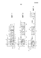
Фиг. 1 изображает общий вид в осевом разрезе двухконтурного газотурбинного двигателя с высокой степенью двухконтурности, содержащего редуктор скорости.FIG. 1 is an axial sectional view of a dual bypass gas turbine engine with a high bypass ratio comprising a speed reducer.
Фиг. 2 - частичный вид двигателя, показанного на фиг. 1, содержащего переднюю часть с редуктором.FIG. 2 is a partial view of the engine shown in FIG. 1, containing the front part with a gear.
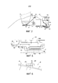
Фиг. 3 - вид двигателя, показанного на фиг. 1, в котором первый модуль отсоединен.FIG. 3 is a view of the engine shown in FIG. 1, in which the first module is disconnected.
Фиг. 4 - вид двигателя, показанного на фиг. 1, в котором все три модуля отсоединены друг от друга.FIG. 4 is a view of the engine shown in FIG. 1, in which all three modules are disconnected from each other.
Фиг. 5 - детальный вид турбинной гайки, установленной на двигателе.FIG. 5 is a detailed view of a turbine nut mounted on an engine.
Фиг. 6 - детальный вид крепления первого модуля на фланце второго модуля.FIG. 6 is a detailed view of the mounting of the first module on the flange of the second module.
Подробное описание варианта осуществления изобретения.Detailed description of an embodiment of the invention.
На фиг. 1 показан турбореактивный двигатель 1 с осью ХХ, который содержит вентилятор S, компрессор 1а низкого давления или наддува, компрессор 1b высокого давления, камеру 1с сгорания, турбину 1d высокого давления и турбину 1е низкого давления. Компрессор 1b высокого давления и турбина 1d высокого давления связаны через вал 4 высокого давления и образуют вместе с ним корпус высокого давления ВД. Компрессор 1а низкого давления и турбина 1е низкого давления связаны через вал 2 низкого давления НД и образуют вместе с ним корпус низкого давления НД.In FIG. 1 shows an XX axis turbojet engine 1 that includes a fan S, a low pressure or
В классических конфигурациях диск, на котором установлены лопатки вентилятора S, приводится во вращение валом передачи мощности или вентиляторным валом 3. Этот вал, в свою очередь, приводится во вращение напрямую валом НД 2. В заявленном двигателе вал 3 передачи мощности приводится во вращение валом НД 2 через редуктор 7 скорости, причем этот редуктор предпочтительно является редуктором с эпициклоидной передачей.In classical configurations, the disk on which the fan blades S is mounted is driven by a power transmission shaft or
В данном случае двигатель разделен на три основных модуля: первый модуль А, называемый вентиляторным модулем, содержит неподвижную часть, содержащую картер вентилятора, образующий кожух вентилятора, промежуточный картер, образующий, кроме всего прочего, опору для различных подшипников 10, 11, 12, и интерфейс крепления на смежном модуле В. Подвижная часть первого модуля А содержит вентилятор S с вентиляторным валом 3, поддерживаемым опорными подшипниками 11 и 12 вентилятора, один из которых является упорным шарикоподшипником, а другой роликоподшипником. Она содержит также компрессор НД 1а, поддерживаемый опорным шарикоподшипником 10 вала низкого давления. Как известно подшипники качения заключены между неподвижным кольцом и подвижным кольцом. Неподвижное кольцо 10 подшипника вала низкого давления установлено на опоре 23 подшипника, и неподвижные кольца подшипников 11 и 12 вентилятора установлены на опоре 22 подшипника, см. фиг. 2. Редуктор 7 скорости расположен между вентилятором и валом НД 2 в пространстве, образованном между опорами 22 и 23, неподвижно соединенными с промежуточным картером.In this case, the engine is divided into three main modules: the first module A, called the fan module, contains a fixed part containing a fan case, forming a fan cover, an intermediate case, which, among other things, forms a support for
Второй основной модуль В тоже содержит подвижные части, такие как вал ВД с компрессором 1b и турбина 1d, и неподвижные части, такие как камера 1с сгорания и все связанные с ней элементы картера, в том числе кожух 5.The second main module B also contains movable parts, such as a VD shaft with
Третий модуль С содержит подвижные части, такие как турбина НД 1е и турбинный вал НД 2, и неподвижные части, такие как выпускной картер, образующий опору подшипников сзади, и выпускное сопло.The third module C comprises movable parts, such as a
Модульная конструкция призвана обеспечить предварительное соединение элементов различных модулей независимо друг от друга таким образом, чтобы они были готовы для сборки без применения сложных операций. Так, первый модуль А можно соединить со следующими модулями путем простого соединения подвижных частей при помощи турбинной гайки, при этом турбинная гайка 14 соединяет приводное средство редуктора скорости с турбинным валом НД 2. Соединение осуществляют также путем болтового соединения неподвижных частей интерфейса модуля А с радиальным фланцем картера модуля В. Пример этого последнего варианта соединения показан на фиг. 6.The modular design is designed to provide a preliminary connection of the elements of various modules independently of each other so that they are ready for assembly without the use of complex operations. So, the first module A can be connected to the following modules by simply connecting the moving parts with a turbine nut, while the
На фиг. 3 показан двигатель, первый модуль которого отсоединен от остальной части двигателя. Как было указано выше, первый модуль отсоединяют путем отвинчивания турбинной гайки 14 и отвинчивания болтов 24, которые удерживают неподвижный интерфейс первого модуля А на радиальном фланце 5R картера 5 второго модуля, см. фиг. 6.In FIG. 3 shows an engine whose first module is disconnected from the rest of the engine. As indicated above, the first module is disconnected by unscrewing the
На фиг. 4 показано отделение друг от друга модулей В и С. Отсоединяя соответствующие элементы картера друг от друга можно отделить два модуля друг от друга в осевом направлении; турбинный вал 2 больше не удерживается турбинной гайкой и может быть отсоединен от второго модуля.In FIG. 4 shows the separation of modules B and C from each other. By disconnecting the corresponding crankcase elements from each other, two modules can be separated from each other in the axial direction; the
На фиг. 2 более детально показана передняя часть двигателя, в котором установлен редуктор 7 между валом 3 передачи мощности, связанным с вентилятором, и валом НД 2. Этот редуктор эпициклоидного типа схематично представлен в виде прямоугольника, чтобы показать только его габарит. На фигурах не показано, но он установлен на опорах 22 и 23 подшипников, связанных с промежуточным картером, и приводится во вращение входной коронной шестерней 8 редуктора, расположенной на входе вала НД, с которым она взаимодействует через приводные средства. Выходной момент этого редуктора 7 передается на вентиляторный вал 3 при помощи классической связи, известной специалисту, например, такой как крепление этого вентиляторного вала на сателлитном водиле в случае эпициклоидного редуктора.In FIG. 2 shows in more detail the front of the engine, in which a
Показанная на фигуре неподвижная часть двигателя содержит внутреннюю стенку 21 тракта первичного потока, входную опору 22 подшипника и выходную опору 23 подшипника. Эти две опоры проходят внутрь газотурбинного двигателя и охватывают упорный подшипник 10, поддерживающий вал НД 2, и шарикоподшипник 11 и роликоподшипник 12 вентиляторного вала 3. Что касается подвижной части, то, кроме ротора вентилятора S, она содержит от входа к выходу вентиляторный вал 3, с которым связаны подвижные кольца подшипников 11 и 12 вентиляторного вала, приводную коронную шестерню 8 редуктора и промежуточный вал 9 удлинения приводной коронной шестерни, который закреплен на подвижном кольце упорного подшипника 10 вала НД 2. Эти неподвижные и подвижные части образуют камеру Е1 и классически сходятся на уровне лабиринтных прокладок, расположенных на ее переднем и заднем концах таким образом, чтобы образовать герметичный объем, заключающий три вышеупомянутых подшипника 10, 11 и 12 и обеспечивающий непрерывность их смазки и их охлаждения. Вышеупомянутые уплотнительные прокладки не показаны, но хорошо известны специалисту в данной области.The stationary part of the engine shown in the figure comprises an
Эта камера Е1 полностью образована первым модулем А, то есть ее можно отсоединить от других модулей, а также от вала НД 4 без утечки содержащегося в ней масла. Кроме того, диаметры приводной коронной шестерни 8 редуктора и промежуточного вала 9 вала НД рассчитаны таким образом, что превышают диаметр вала НД 2, то есть позволяют ввести цилиндрической инструмент, чтобы достигнуть гайки крепления вала НД 2 на подвижном кольце его упорного подшипника 10 и обеспечить ее отвинчивание без помех со стороны этих двух деталей.This chamber E1 is completely formed by the first module A, that is, it can be disconnected from other modules, as well as from the ND 4 shaft without leakage of the oil contained in it. In addition, the diameters of the
На фиг. 5 более детально показана турбинная гайка, установленная на турбинном валу.In FIG. 5 shows in more detail a turbine nut mounted on a turbine shaft.
Начиная от выхода, вал НД 2 зацепляется при помощи шлицевой системы 132 с цапфой 13, которая соединена с подвижным кольцом 10М упорного подшипника 10 и которая продолжена в сторону выхода валом компрессора 1а низкого давления и приводит во вращение ротор компрессора 1а низкого давления. Вал НД 2 удерживается на месте в осевом направлении на этой цапфе при помощи турбинной гайки 14, которую завинчивают на резьбе 142, выполненной на внутренней стороне вала НД 2, и которая опирается на осевой упор 15, проходящий радиально внутрь, начиная от цапфы 13. Эта гайка 14, которая соединяет вал НД 2 с цапфой 13, доступна спереди двигателя, хотя и требует предварительного демонтажа капота с его переднего конца, но вместе с тем не требует демонтажа других деталей и, в частности, элементов, образующих стенки камеры Е1. Таким образом, достигается технический результат изобретения, то есть возможность демонтажа вала НД 2 без разборки камеры Е1.Starting from the outlet, the
Как показано также на фиг. 5, в сторону входа на цапфе 13 установлен промежуточный вал 9, который образует приводное средство входной коронной шестерни 8 редуктора и который находится в радиальном направлении между цапфой 13 и подвижным кольцом 10М упорного подшипника 10 вала НД, с которым он жестко связан. Этот промежуточный вал 9 продолжает коронную шестерню 8 и позволяет ее демонтировать вместе с цапфой 13, хотя это разделение коронной шестерни на два отдельных элемента, то есть на собственно коронную шестерню 8 и промежуточный вал 9, не является существенным признаком изобретения. Выходной конец этого промежуточного вала 9 расположен вокруг вала НД 2 и за счет большего диаметра вала обеспечивает доступ к гайке 14 крепления вала НД спереди двигателя. Он образует вместе с приводной коронной шестерней 8 элемент стенки передней камеры Е1, который можно отсоединить от вала НД 2, но который может оставаться на месте и поддерживать объемную целостность передней камеры Е1 при извлечении вала НД 2.As also shown in FIG. 5, an
Наконец, приводная коронная шестерня 8 редуктора установлена на промежуточном валу 9 при помощи шлиц, которые обеспечивают взаимодействие двух валов и приведение во вращение коронной шестерни 8 и, следовательно, редуктора 7 от вала НД 2. Как было указано выше, она имеет диаметр, превышающий диаметр вала НД 2.Finally, the
Как показано на фиг. 5, на входном концевом участке цапфы 13 завинчена гайка 16, которая упирается в осевом направлении в заплечик 9е промежуточного вала 9. Сам промежуточный вал 9 опирается в осевом направлении на подвижное кольцо 10М подшипника 10, поддерживающего входной конец турбинного вала НД 2. Таким образом, эта гайка 16 стопорит в осевом направлении приводной вал компрессора 1а низкого давления. При помощи этой гайки ротор компрессора низкого давления, называемого также компрессором наддува, удерживается на месте в первом модуле А, которым можно манипулировать без риска повреждения этой подвижной части.As shown in FIG. 5, a
Гайка 16 имеет диаметр, превышающий диаметр гайки 14, и, следовательно, не мешает прохождению инструмента монтажа/демонтажа гайки 14.The
Claims (11)
Applications Claiming Priority (3)
| Application Number | Priority Date | Filing Date | Title |
|---|---|---|---|
| FR1361460A FR3013388B1 (en) | 2013-11-21 | 2013-11-21 | ENGINE, SUCH AS A TURBOJET, MODULAR WITH SPEED REDUCER |
| FR1361460 | 2013-11-21 | ||
| PCT/FR2014/052846 WO2015075345A1 (en) | 2013-11-21 | 2014-11-06 | Modular engine, such as a jet engine, with a speed reduction gear |
Publications (2)
| Publication Number | Publication Date |
|---|---|
| RU2016119153A RU2016119153A (en) | 2017-12-26 |
| RU2674098C1 true RU2674098C1 (en) | 2018-12-04 |
Family
ID=50289833
Family Applications (1)
| Application Number | Title | Priority Date | Filing Date |
|---|---|---|---|
| RU2016119153A RU2674098C1 (en) | 2013-11-21 | 2014-11-06 | Modular engine, such as jet engine, with speed reduction gear |
Country Status (8)
| Country | Link |
|---|---|
| US (1) | US10473035B2 (en) |
| EP (1) | EP3071792B1 (en) |
| CN (1) | CN105765166B (en) |
| BR (1) | BR112016011122B1 (en) |
| CA (1) | CA2929947C (en) |
| FR (1) | FR3013388B1 (en) |
| RU (1) | RU2674098C1 (en) |
| WO (1) | WO2015075345A1 (en) |
Families Citing this family (22)
| Publication number | Priority date | Publication date | Assignee | Title |
|---|---|---|---|---|
| FR3013385B1 (en) * | 2013-11-21 | 2015-11-13 | Snecma | PRE-SEALED SPEAKER DURING MODULAR DISASSEMBLY OF A REDUCING TURBOREACTOR |
| FR3046202B1 (en) | 2015-12-24 | 2017-12-29 | Snecma | TURBOREACTOR WITH MEANS OF PUSH RESUME ON THE INTER-COMPRESSOR HOUSING |
| FR3046201B1 (en) | 2015-12-24 | 2018-01-19 | Safran Aircraft Engines | TURBOREACTOR WITH MEANS OF PUSH RESUME ON THE INTER-COMPRESSOR HOUSING |
| BE1025131B1 (en) * | 2017-04-11 | 2018-11-14 | Safran Aero Boosters S.A. | DOUBLE-CURVED TRANSMISSION SHAFT FOR TURBOMACHINE |
| US11168828B2 (en) | 2017-05-02 | 2021-11-09 | Pratt & Whitney Canada Corp. | Gas turbine engine casing arrangement |
| FR3075861B1 (en) | 2017-12-22 | 2019-11-15 | Safran Aircraft Engines | DYNAMIC SEAL BETWEEN TWO ROTORS OF AN AIRCRAFT TURBOMACHINE |
| FR3075860B1 (en) | 2017-12-22 | 2019-11-29 | Safran Aircraft Engines | DYNAMIC SEAL BETWEEN TWO ROTORS OF AN AIRCRAFT TURBOMACHINE |
| FR3086343B1 (en) * | 2018-09-24 | 2020-09-04 | Safran Aircraft Engines | TURBOMACHINE WITH REDUCER FOR AN AIRCRAFT |
| FR3087819B1 (en) * | 2018-10-26 | 2020-11-13 | Safran Aircraft Engines | AIRCRAFT TURBOMACHINE EQUIPPED WITH AN ELECTRIC MACHINE |
| GB201817937D0 (en) * | 2018-11-02 | 2018-12-19 | Rolls Royce Plc | Gas turbine engine |
| DE102019102450B4 (en) * | 2019-01-31 | 2023-07-20 | Rolls-Royce Deutschland Ltd & Co Kg | Method of assembling a gear module of a gas turbine engine |
| DE102019102429A1 (en) * | 2019-01-31 | 2020-08-06 | Rolls-Royce Deutschland Ltd & Co Kg | Gas turbine engine for an aircraft |
| GB201903703D0 (en) * | 2019-03-19 | 2019-05-01 | Rolls Royce Plc | A gas turbine engine bearing support structure |
| US11174916B2 (en) | 2019-03-21 | 2021-11-16 | Pratt & Whitney Canada Corp. | Aircraft engine reduction gearbox |
| CN109854377A (en) * | 2019-04-08 | 2019-06-07 | 沈阳建筑大学 | A kind of novel aerial turbo fan engine |
| FR3115822B1 (en) | 2020-11-04 | 2022-09-30 | Safran Aircraft Engines | MODULARITY OF AN AIRCRAFT TURBOMACHINE |
| FR3115823B1 (en) | 2020-11-04 | 2022-09-30 | Safran Aircraft Engines | MODULARITY OF AN AIRCRAFT TURBOMACHINE |
| US11365630B1 (en) * | 2020-12-28 | 2022-06-21 | Rolls-Royce North American Technologies Inc. | Fan rotor with tapered drive joint |
| US11268453B1 (en) | 2021-03-17 | 2022-03-08 | Pratt & Whitney Canada Corp. | Lubrication system for aircraft engine reduction gearbox |
| CN112983651B (en) * | 2021-04-26 | 2023-07-28 | 黄锴 | Small aviation double-rotor unmanned aerial vehicle engine |
| FR3140124A1 (en) * | 2022-09-26 | 2024-03-29 | Safran Aircraft Engines | TURBOMACHINE COMPRISING SEVERAL MODULES AND A DEVICE FOR BLOCKING THESE MODULES, AND CORRESPONDING DISASSEMBLY METHOD |
| FR3140123A1 (en) | 2022-09-26 | 2024-03-29 | Safran Aircraft Engines | MODULARITY OF AN AIRCRAFT TURBOMACHINE BY AN AXIAL AND ROTATIONAL LOCKING DEVICE, CORRESPONDING ASSEMBLY METHOD |
Citations (4)
| Publication number | Priority date | Publication date | Assignee | Title |
|---|---|---|---|---|
| US20090081039A1 (en) * | 2007-09-25 | 2009-03-26 | Mccune Michael E | Gas turbine engine front architecture modularity |
| EP2327859A2 (en) * | 2009-11-30 | 2011-06-01 | United Technologies Corporation | Mounting system for a planetary gear train in a gas turbine engine |
| US20120257960A1 (en) * | 2009-11-20 | 2012-10-11 | United Technologies Corporation | Engine Bearing Support |
| US8402741B1 (en) * | 2012-01-31 | 2013-03-26 | United Technologies Corporation | Gas turbine engine shaft bearing configuration |
Family Cites Families (4)
| Publication number | Priority date | Publication date | Assignee | Title |
|---|---|---|---|---|
| FR2866073B1 (en) * | 2004-02-11 | 2006-07-28 | Snecma Moteurs | TURBOREACTOR HAVING TWO SOLIDARITY CONTRAROTATIVE BLOWERS OF A CONTRAROTATIVE LOW-PRESSURE COMPRESSOR |
| FR2896826B1 (en) | 2006-01-30 | 2008-04-25 | Snecma Sa | ENGINE SHAFT CONNECTION SYSTEM WITH RETRACTABLE NUT |
| ITFI20110269A1 (en) * | 2011-12-12 | 2013-06-13 | Nuovo Pignone Spa | "TURNING GEAR FOR GAS TURBINE ARRANGEMENTS" |
| ES2695074T3 (en) * | 2011-12-30 | 2018-12-28 | United Technologies Corporation | Lubrication of gas turbine engine |
-
2013
- 2013-11-21 FR FR1361460A patent/FR3013388B1/en active Active
-
2014
- 2014-11-06 EP EP14806028.8A patent/EP3071792B1/en active Active
- 2014-11-06 CA CA2929947A patent/CA2929947C/en active Active
- 2014-11-06 BR BR112016011122-2A patent/BR112016011122B1/en active IP Right Grant
- 2014-11-06 RU RU2016119153A patent/RU2674098C1/en active
- 2014-11-06 US US15/037,397 patent/US10473035B2/en active Active
- 2014-11-06 WO PCT/FR2014/052846 patent/WO2015075345A1/en active Application Filing
- 2014-11-06 CN CN201480063462.6A patent/CN105765166B/en active Active
Patent Citations (4)
| Publication number | Priority date | Publication date | Assignee | Title |
|---|---|---|---|---|
| US20090081039A1 (en) * | 2007-09-25 | 2009-03-26 | Mccune Michael E | Gas turbine engine front architecture modularity |
| US20120257960A1 (en) * | 2009-11-20 | 2012-10-11 | United Technologies Corporation | Engine Bearing Support |
| EP2327859A2 (en) * | 2009-11-30 | 2011-06-01 | United Technologies Corporation | Mounting system for a planetary gear train in a gas turbine engine |
| US8402741B1 (en) * | 2012-01-31 | 2013-03-26 | United Technologies Corporation | Gas turbine engine shaft bearing configuration |
Also Published As
| Publication number | Publication date |
|---|---|
| CN105765166A (en) | 2016-07-13 |
| EP3071792B1 (en) | 2020-12-30 |
| BR112016011122B1 (en) | 2022-04-12 |
| CN105765166B (en) | 2019-04-05 |
| CA2929947A1 (en) | 2015-05-28 |
| CA2929947C (en) | 2022-12-06 |
| WO2015075345A1 (en) | 2015-05-28 |
| FR3013388B1 (en) | 2019-03-22 |
| US10473035B2 (en) | 2019-11-12 |
| FR3013388A1 (en) | 2015-05-22 |
| US20160298548A1 (en) | 2016-10-13 |
| BR112016011122A2 (en) | 2017-08-08 |
| EP3071792A1 (en) | 2016-09-28 |
| RU2016119153A (en) | 2017-12-26 |
Similar Documents
| Publication | Publication Date | Title |
|---|---|---|
| RU2674098C1 (en) | Modular engine, such as jet engine, with speed reduction gear | |
| RU2674837C1 (en) | Sealed front chamber during modular dismantling of turbojet with reduction gear | |
| US11352957B2 (en) | Compact accessory systems for a gas turbine engine | |
| RU2673027C2 (en) | Assembly for aircraft gas-turbine engine and method of its mounting | |
| US7500365B2 (en) | Accessory gearbox | |
| RU2686248C2 (en) | Front part of aircraft double-flow gas turbine engine and aircraft double-flow gas turbine engine | |
| RU2468213C2 (en) | Installation of shaft into bearing with self-removable nut | |
| US10267365B2 (en) | Power gearbox pin arrangement | |
| US11415045B2 (en) | Aircraft turbomachine with mechanical reducer and contrarotative turbine | |
| RU2522344C2 (en) | Gas turbine engine and disassembly of its front part | |
| US9765649B2 (en) | Borescope inspection port fitting | |
| US11143110B2 (en) | Aeroderivative jet engine accessory starter relocation to main shaft—directly connected to HPC shaft | |
| US20170362959A1 (en) | Lubrication system with multiple lubrication circuits | |
| JP2013096410A (en) | Gas turbine engine and maintenance method of gas turbine engine | |
| GB2569006A (en) | Arm for turbomachine casing comprising a body and a removable part | |
| US20220003354A1 (en) | Gas turbine engine casing arrangement | |
| RU2525038C2 (en) | Method of gas turbine engine servicing (versions) and gas turbine engine | |
| CN116568908A (en) | Modularization of aircraft turbines | |
| US11680525B2 (en) | Lubricant filter for a turbine engine | |
| US20240003303A1 (en) | Modularity of an aircraft turbomachine | |
| RU2788264C2 (en) | Aviation gas-turbine engine with at least two cases and with power takeoff | |
| RU2711895C2 (en) | Double-flow jet turbine engine |
Legal Events
| Date | Code | Title | Description |
|---|---|---|---|
| PD4A | Correction of name of patent owner |