RU2672259C2 - Dc power distribution system - Google Patents
Dc power distribution system Download PDFInfo
- Publication number
- RU2672259C2 RU2672259C2 RU2015144900A RU2015144900A RU2672259C2 RU 2672259 C2 RU2672259 C2 RU 2672259C2 RU 2015144900 A RU2015144900 A RU 2015144900A RU 2015144900 A RU2015144900 A RU 2015144900A RU 2672259 C2 RU2672259 C2 RU 2672259C2
- Authority
- RU
- Russia
- Prior art keywords
- communication
- signals
- rail
- energy
- communication device
- Prior art date
Links
- 238000004891 communication Methods 0.000 claims abstract description 319
- 230000010354 integration Effects 0.000 abstract description 3
- 238000004870 electrical engineering Methods 0.000 abstract 2
- 239000000126 substance Substances 0.000 abstract 1
- 238000005516 engineering process Methods 0.000 description 15
- 239000004020 conductor Substances 0.000 description 11
- 230000006870 function Effects 0.000 description 11
- 238000000034 method Methods 0.000 description 8
- 230000004907 flux Effects 0.000 description 7
- 230000005540 biological transmission Effects 0.000 description 5
- 238000004146 energy storage Methods 0.000 description 5
- 230000007423 decrease Effects 0.000 description 4
- 238000009434 installation Methods 0.000 description 4
- 238000004378 air conditioning Methods 0.000 description 3
- 239000003990 capacitor Substances 0.000 description 3
- 230000001419 dependent effect Effects 0.000 description 3
- 238000004590 computer program Methods 0.000 description 2
- 230000015572 biosynthetic process Effects 0.000 description 1
- 230000003247 decreasing effect Effects 0.000 description 1
- 238000001914 filtration Methods 0.000 description 1
- 238000010438 heat treatment Methods 0.000 description 1
- 238000010397 one-hybrid screening Methods 0.000 description 1
- 230000003287 optical effect Effects 0.000 description 1
- 230000002093 peripheral effect Effects 0.000 description 1
- 230000004044 response Effects 0.000 description 1
- 239000007787 solid Substances 0.000 description 1
- 230000005236 sound signal Effects 0.000 description 1
- 238000001228 spectrum Methods 0.000 description 1
- 238000009423 ventilation Methods 0.000 description 1
Images
Classifications
-
- H—ELECTRICITY
- H02—GENERATION; CONVERSION OR DISTRIBUTION OF ELECTRIC POWER
- H02J—CIRCUIT ARRANGEMENTS OR SYSTEMS FOR SUPPLYING OR DISTRIBUTING ELECTRIC POWER; SYSTEMS FOR STORING ELECTRIC ENERGY
- H02J13/00—Circuit arrangements for providing remote indication of network conditions, e.g. an instantaneous record of the open or closed condition of each circuitbreaker in the network; Circuit arrangements for providing remote control of switching means in a power distribution network, e.g. switching in and out of current consumers by using a pulse code signal carried by the network
- H02J13/00006—Circuit arrangements for providing remote indication of network conditions, e.g. an instantaneous record of the open or closed condition of each circuitbreaker in the network; Circuit arrangements for providing remote control of switching means in a power distribution network, e.g. switching in and out of current consumers by using a pulse code signal carried by the network characterised by information or instructions transport means between the monitoring, controlling or managing units and monitored, controlled or operated power network element or electrical equipment
- H02J13/00007—Circuit arrangements for providing remote indication of network conditions, e.g. an instantaneous record of the open or closed condition of each circuitbreaker in the network; Circuit arrangements for providing remote control of switching means in a power distribution network, e.g. switching in and out of current consumers by using a pulse code signal carried by the network characterised by information or instructions transport means between the monitoring, controlling or managing units and monitored, controlled or operated power network element or electrical equipment using the power network as support for the transmission
-
- H02J13/0003—
-
- H—ELECTRICITY
- H04—ELECTRIC COMMUNICATION TECHNIQUE
- H04B—TRANSMISSION
- H04B3/00—Line transmission systems
- H04B3/54—Systems for transmission via power distribution lines
- H04B3/548—Systems for transmission via power distribution lines the power on the line being DC
-
- H—ELECTRICITY
- H05—ELECTRIC TECHNIQUES NOT OTHERWISE PROVIDED FOR
- H05B—ELECTRIC HEATING; ELECTRIC LIGHT SOURCES NOT OTHERWISE PROVIDED FOR; CIRCUIT ARRANGEMENTS FOR ELECTRIC LIGHT SOURCES, IN GENERAL
- H05B47/00—Circuit arrangements for operating light sources in general, i.e. where the type of light source is not relevant
- H05B47/10—Controlling the light source
- H05B47/175—Controlling the light source by remote control
- H05B47/185—Controlling the light source by remote control via power line carrier transmission
-
- H—ELECTRICITY
- H05—ELECTRIC TECHNIQUES NOT OTHERWISE PROVIDED FOR
- H05B—ELECTRIC HEATING; ELECTRIC LIGHT SOURCES NOT OTHERWISE PROVIDED FOR; CIRCUIT ARRANGEMENTS FOR ELECTRIC LIGHT SOURCES, IN GENERAL
- H05B47/00—Circuit arrangements for operating light sources in general, i.e. where the type of light source is not relevant
- H05B47/10—Controlling the light source
- H05B47/175—Controlling the light source by remote control
- H05B47/19—Controlling the light source by remote control via wireless transmission
-
- H—ELECTRICITY
- H02—GENERATION; CONVERSION OR DISTRIBUTION OF ELECTRIC POWER
- H02J—CIRCUIT ARRANGEMENTS OR SYSTEMS FOR SUPPLYING OR DISTRIBUTING ELECTRIC POWER; SYSTEMS FOR STORING ELECTRIC ENERGY
- H02J13/00—Circuit arrangements for providing remote indication of network conditions, e.g. an instantaneous record of the open or closed condition of each circuitbreaker in the network; Circuit arrangements for providing remote control of switching means in a power distribution network, e.g. switching in and out of current consumers by using a pulse code signal carried by the network
- H02J13/00006—Circuit arrangements for providing remote indication of network conditions, e.g. an instantaneous record of the open or closed condition of each circuitbreaker in the network; Circuit arrangements for providing remote control of switching means in a power distribution network, e.g. switching in and out of current consumers by using a pulse code signal carried by the network characterised by information or instructions transport means between the monitoring, controlling or managing units and monitored, controlled or operated power network element or electrical equipment
- H02J13/00019—Circuit arrangements for providing remote indication of network conditions, e.g. an instantaneous record of the open or closed condition of each circuitbreaker in the network; Circuit arrangements for providing remote control of switching means in a power distribution network, e.g. switching in and out of current consumers by using a pulse code signal carried by the network characterised by information or instructions transport means between the monitoring, controlling or managing units and monitored, controlled or operated power network element or electrical equipment using optical means
-
- H—ELECTRICITY
- H02—GENERATION; CONVERSION OR DISTRIBUTION OF ELECTRIC POWER
- H02J—CIRCUIT ARRANGEMENTS OR SYSTEMS FOR SUPPLYING OR DISTRIBUTING ELECTRIC POWER; SYSTEMS FOR STORING ELECTRIC ENERGY
- H02J13/00—Circuit arrangements for providing remote indication of network conditions, e.g. an instantaneous record of the open or closed condition of each circuitbreaker in the network; Circuit arrangements for providing remote control of switching means in a power distribution network, e.g. switching in and out of current consumers by using a pulse code signal carried by the network
- H02J13/00006—Circuit arrangements for providing remote indication of network conditions, e.g. an instantaneous record of the open or closed condition of each circuitbreaker in the network; Circuit arrangements for providing remote control of switching means in a power distribution network, e.g. switching in and out of current consumers by using a pulse code signal carried by the network characterised by information or instructions transport means between the monitoring, controlling or managing units and monitored, controlled or operated power network element or electrical equipment
- H02J13/0002—Circuit arrangements for providing remote indication of network conditions, e.g. an instantaneous record of the open or closed condition of each circuitbreaker in the network; Circuit arrangements for providing remote control of switching means in a power distribution network, e.g. switching in and out of current consumers by using a pulse code signal carried by the network characterised by information or instructions transport means between the monitoring, controlling or managing units and monitored, controlled or operated power network element or electrical equipment using ultrasonic means
-
- H—ELECTRICITY
- H02—GENERATION; CONVERSION OR DISTRIBUTION OF ELECTRIC POWER
- H02J—CIRCUIT ARRANGEMENTS OR SYSTEMS FOR SUPPLYING OR DISTRIBUTING ELECTRIC POWER; SYSTEMS FOR STORING ELECTRIC ENERGY
- H02J13/00—Circuit arrangements for providing remote indication of network conditions, e.g. an instantaneous record of the open or closed condition of each circuitbreaker in the network; Circuit arrangements for providing remote control of switching means in a power distribution network, e.g. switching in and out of current consumers by using a pulse code signal carried by the network
- H02J13/00006—Circuit arrangements for providing remote indication of network conditions, e.g. an instantaneous record of the open or closed condition of each circuitbreaker in the network; Circuit arrangements for providing remote control of switching means in a power distribution network, e.g. switching in and out of current consumers by using a pulse code signal carried by the network characterised by information or instructions transport means between the monitoring, controlling or managing units and monitored, controlled or operated power network element or electrical equipment
- H02J13/00022—Circuit arrangements for providing remote indication of network conditions, e.g. an instantaneous record of the open or closed condition of each circuitbreaker in the network; Circuit arrangements for providing remote control of switching means in a power distribution network, e.g. switching in and out of current consumers by using a pulse code signal carried by the network characterised by information or instructions transport means between the monitoring, controlling or managing units and monitored, controlled or operated power network element or electrical equipment using wireless data transmission
-
- H—ELECTRICITY
- H04—ELECTRIC COMMUNICATION TECHNIQUE
- H04B—TRANSMISSION
- H04B2203/00—Indexing scheme relating to line transmission systems
- H04B2203/54—Aspects of powerline communications not already covered by H04B3/54 and its subgroups
- H04B2203/5462—Systems for power line communications
- H04B2203/547—Systems for power line communications via DC power distribution
Abstract
Description
ОБЛАСТЬ ТЕХНИКИFIELD OF TECHNOLOGY
Данное изобретение относится к системе распределения энергии постоянного тока (DC)для распределения энергии постоянного тока. Также изобретение относится к устройству связи, способу связи и компьютерной программе связи для использования в системе распределения энергии постоянного тока.This invention relates to a DC energy distribution system (DC) for distributing DC energy. The invention also relates to a communication device, a communication method and a computer communication program for use in a DC power distribution system.
УРОВЕНЬ ТЕХНИКИ ИЗОБРЕТЕНИЯBACKGROUND OF THE INVENTION
В стандарте EMerge, Version 1.1, дается определение системе распределения энергии постоянного тока для распределения энергии постоянного тока, которая обеспечивается источником энергии постоянного тока, через рельс (рейку) на одну или несколько электрических нагрузок, подключенных к рельсу. Система распределения энергии постоянного тока не обеспечивает функциональные возможности управления для управления, например, источником энергии постоянного тока или одной или несколькими электрическими нагрузками. Таким образом, поскольку рельс находится всегда под воздействием энергии постоянного тока, согласно стандарту EMerge, то одна или несколько нагрузок, подключенных к рельсу, всегда находятся во включенном состоянии, за исключением случаев, когда их отключают, например, вручную.The EMerge Standard, Version 1.1, defines a DC power distribution system for distributing DC power, which is provided by a DC power source, through a rail (rail) to one or more electrical loads connected to the rail. The DC power distribution system does not provide control functionality for controlling, for example, a DC power source or one or more electrical loads. Thus, since the rail is always under the influence of direct current energy, according to the EMerge standard, one or more loads connected to the rail are always on, except when they are disconnected, for example, manually.
СУЩНОСТЬ ИЗОБРЕТЕНИЯSUMMARY OF THE INVENTION
Задачей данного изобретения является обеспечение системы распределения энергии постоянного тока для распределения энергии постоянного тока, которая выполнена таким образом, чтобы функциональные возможности управления могли быть легко интегрированы в систему распределения энергии постоянного тока.An object of the present invention is to provide a direct current power distribution system for direct current power distribution, which is designed so that the control functionality can be easily integrated into the direct current power distribution system.
Согласно первому аспекту настоящего изобретения представлена система распределения энергии постоянного тока, причем система содержит:According to a first aspect of the present invention, there is provided a DC power distribution system, the system comprising:
- рельс для распределения энергии постоянного тока, причем рельс выполнен с возможностью обеспечивать связь по линиям электропередачи;- a rail for distributing direct current energy, and the rail is configured to provide communication over power lines;
- источник энергии для подачи энергии постоянного тока на рельс;- an energy source for supplying direct current energy to the rail;
- электрическую нагрузку, подключенную к рельсу, для приема энергии постоянного тока и;- an electrical load connected to the rail for receiving direct current energy and;
- устройство связи, присоединенное к рельсу, причем устройство связи выполнено с возможностью: а) беспроводным образом принимать сигналы связи и передавать принятые сигналы связи посредством связи по линиям электропередачи на источник энергии и/или электрическую нагрузку; и/или б) принимать сигналы связи посредством связи по линиям электропередачи от источника энергии и/или электрической нагрузки, и беспроводным образом передавать принятые сигналы связи.- a communication device attached to the rail, the communication device configured to: a) wirelessly receive communication signals and transmit received communication signals through communication via power lines to an energy source and / or electrical load; and / or b) receive communication signals through communication via power lines from an energy source and / or electrical load, and wirelessly transmit received communication signals.
Поскольку устройство связи, присоединенное к рельсу, выполнено с возможностью а) беспроводным способом принимать сигналы связи и передавать принятые сигналы связи посредством связи по линиям электропередачи на источник энергии и/или электрическую нагрузку; и/или б) принимать сигналы связи посредством связи по линиям электропередачи от источника энергии и/или электрической нагрузки, и беспроводным способом передавать принятые сигналы связи, то обеспечивается настройка связи, которая обеспечивает легкую интеграцию функциональных возможностей управления для управления, например, источником энергии и/или электрической нагрузкой путем передачи управляющих сигналов через устройство связи.Since the communication device attached to the rail is configured to: a) wirelessly receive communication signals and transmit the received communication signals through communication via power lines to an energy source and / or electrical load; and / or b) to receive communication signals through communication via power lines from an energy source and / or electric load, and to transmit received communication signals wirelessly, then a communication setting is provided that provides easy integration of control functionality for controlling, for example, an energy source and / or electrical load by transmitting control signals through a communication device.
Рельс предпочтительно является компонентом токопроводящей шины согласно стандарту EMerge, а источник энергии предпочтительно является модулем источника энергии согласно стандарту EМerge. Источник энергии предпочтительно выполнен с возможностью приема энергии переменного тока и преобразования принятой энергии переменного тока в энергию постоянного тока. Энергия переменного тока может быть принята электрической сети. В электрической нагрузкой, которая может быть периферической, согласно стандарту EМerge, предпочтительно является светильник. Однако электрической нагрузкой также может быть другой электропотребитель, например датчик, блок отопления, вентиляции и/или кондиционирования и так далее.The rail is preferably a component of the conductive bus according to the EMerge standard, and the power source is preferably a module of the power source according to the EMerge standard. The energy source is preferably configured to receive alternating current energy and convert the received alternating current energy into direct current energy. AC power can be taken by the electrical network. In an electrical load, which may be peripheral, according to the EMerge standard, a luminaire is preferably. However, the electrical load may also be another electrical consumer, for example a sensor, a heating, ventilation and / or air conditioning unit, and so on.
В предпочтительном варианте осуществления система распределения энергии постоянного тока также включает в себя блок управления для управления источником энергии и/или электрической нагрузкой, причем блок управления выполнен с возможностью беспроводным образом передавать управляющие сигналы в виде сигналов связи на устройство связи, а устройство связи выполнено с возможностью передавать сигналы связи на источник энергии и/или электрическую нагрузку посредством связи по линиям электропередачи для управления источником энергии и/или электрической нагрузкой.In a preferred embodiment, the DC power distribution system also includes a control unit for controlling the energy source and / or the electrical load, the control unit being configured to wirelessly transmit control signals in the form of communication signals to the communication device, and the communication device is configured to transmit communication signals to an energy source and / or electrical load through communication via power lines to control the energy source and / or electrical load.
Система распределения энергии постоянного тока может содержать один или несколько рельсов, причем если система распределения энергии постоянного тока содержит несколько рельсов, смонтированных на потолке помещения, то такие рельсы могут образовывать потолочную решетку. Блок управления предпочтительно монтируется не на потолке, а, например, на стене помещения с тем, чтобы с помощью прикрепленного к стенке блока управления можно было управлять источником энергии и/или электрической нагрузкой. Блок управления может также быть выполнен в виде переносного блока, аналогичного мобильному телефону, который выполнен с возможностью передавать управляющие сигналы на устройство связи.The direct current energy distribution system may comprise one or more rails, and if the direct current energy distribution system comprises several rails mounted on the ceiling of the room, such rails may form a ceiling grid. The control unit is preferably mounted not on the ceiling, but, for example, on the wall of the room so that it is possible to control the energy source and / or electric load using the control unit attached to the wall. The control unit may also be in the form of a portable unit similar to a mobile phone, which is configured to transmit control signals to a communication device.
Предпочтительно, чтобы система распределения энергии постоянного тока содержала как минимум два рельса для распределения энергии постоянного тока, которые выполнены с возможностью обеспечивать связь по линиям электропередачи, причем к каждому из этих, по меньшей мере, двух рельсов присоединено устройство связи, причем устройства связи выполнены с возможностью беспроводным образом передавать сигналы связи между рельсами и передавать сигналы связи посредством связи по линиям электропередачи, обеспеченной соответствующим рельсом. Таким образом, блоки, присоединенные к различным рельсам системы распределения энергии постоянного тока, например электрические нагрузки и/или источники энергии, присоединенные к различным рельсам системы распределения энергии постоянного тока, могут осуществлять связь друг с другом через устройства связи, улучшая тем самым функциональные возможности связи системы распределения энергии постоянного тока.Preferably, the direct current energy distribution system comprises at least two rails for distributing direct current energy, which are configured to provide communication over power lines, and a communication device is connected to each of these at least two rails, the communication devices being made with the ability to wirelessly transmit communication signals between the rails and transmit communication signals through communication over power lines provided by the corresponding rail. Thus, blocks connected to different rails of a DC power distribution system, for example, electrical loads and / or energy sources connected to different rails of a DC power distribution system, can communicate with each other via communication devices, thereby improving communication functionality DC power distribution systems.
Устройство связи может быть отдельным от источника энергии и электрической нагрузки. Это позволяет модифицировать существующую систему распределения энергии постоянного тока, отдельно присоединив к рельсу устройство связи, избежав при этом необходимости модифицировать рельс, источник энергии и/или электрическую нагрузку, так что система распределения энергии постоянного тока может быть обеспечена с улучшенными функциональными возможностями связи.The communication device may be separate from the energy source and the electrical load. This allows you to modify the existing DC power distribution system by separately connecting the communication device to the rail, while avoiding the need to modify the rail, power source and / or electrical load, so that the DC power distribution system can be provided with improved communication functionality.
Устройство связи предпочтительно выполнено с возможностью закрепления на рельсе. Таким образом, устройство связи можно считать зажимным вводом, который может легко крепиться к рельсу путем фиксации, и который вводит принятый беспроводным образом сигнал связи в связь по линиям электропередачи, обеспечиваемую рельсом.The communication device is preferably configured to be mounted on a rail. Thus, the communication device can be considered a clamping input, which can be easily fixed to the rail by fixing, and which introduces a wirelessly received communication signal into the communication via power lines provided by the rail.
В предпочтительном варианте осуществления система распределения энергии постоянного тока выполнена с возможностью интеграции в подвесной потолок, причем рельс имеет выступ для удержания плиток подвесного потолка и при этом внешняя форма устройства связи выполнена такой, чтобы устройство связи не препятствовало размещению на выступе или удалению с выступа, если устройство связи присоединено к рельсу.In a preferred embodiment, the direct current energy distribution system is adapted to be integrated into the suspended ceiling, the rail having a protrusion to hold the tiles of the suspended ceiling and the external form of the communication device is designed so that the communication device does not interfere with placement on the protrusion or removal from the protrusion, if The communication device is attached to the rail.
Устройство связи может быть выполнено так, что его ширина уменьшается по мере уменьшения расстояния до выступов несущего элемента на плоскости, перпендикулярной направлению по длине рельса. Так, например, устройство связи может иметь, по меньшей мере, частично по существу коническое поперечное сечение и/или в поперечном сечении противоположные стороны устройства связи могут быть скруглены, например иметь форму сектора окружности. Такая внешняя форма устройства связи может обеспечивать больше пространства по боковым сторонам рельса, к которому подсоединено устройство связи, за счет чего пользователь получает возможность удалять или снимать плитки подвесного потолка с выступа и при этом ему не мешает часть внешней формы устройства связи. Это может способствовать установке подвесного потолка с интегрированной системой распределения энергии постоянного тока.The communication device can be made so that its width decreases with decreasing distance to the protrusions of the bearing element on a plane perpendicular to the direction along the length of the rail. So, for example, the communication device can have at least partially essentially conical cross section and / or in cross section opposite sides of the communication device can be rounded, for example in the form of a circle sector. Such an external form of the communication device can provide more space on the side of the rail to which the communication device is connected, due to which the user is able to remove or remove tiles from the ledge from the ledge and at the same time does not interfere with part of the external form of the communication device. This may facilitate the installation of a false ceiling with an integrated DC power distribution system.
Устройство связи может быть интегрировано в источник энергии или электрическую нагрузку. Таким образом устройство связи может быть опосредованно присоединено к рельсу за счет присоединения к нему соответствующего источника энергии или электрической нагрузки с интегрированным устройством связи. Как следствие, устраняется необходимость монтажа дополнительного устройства, являющегося устройством связи, поскольку будет достаточно просто смонтировать источник энергии и электрическую нагрузку, в результате чего конечный монтаж системы распределения энергии постоянного тока станет еще проще.The communication device may be integrated into an energy source or electrical load. Thus, the communication device can be indirectly connected to the rail by attaching to it an appropriate energy source or electric load with an integrated communication device. As a result, the need to install an additional device, which is a communication device, is eliminated, since it will be quite simple to mount the energy source and electric load, as a result of which the final installation of the DC energy distribution system will become even easier.
Система распределения энергии постоянного тока может содержать одно или несколько устройств связи. В том случае, если система распределения энергии постоянного тока содержит несколько устройств связи, то устройства связи могут быть интегрированы в источник энергии и/или электрическую нагрузку. Кроме того, система распределения энергии постоянного тока может содержать по меньшей мере одно устройство связи, интегрированное в источник энергии и/или электрическую нагрузку, и по меньшей мере одно дополнительное отдельное устройство связи, напрямую присоединенное к рельсу.A DC power distribution system may include one or more communication devices. In the event that the DC power distribution system comprises several communication devices, then the communication devices can be integrated into an energy source and / or an electrical load. In addition, the DC power distribution system may include at least one communication device integrated into the energy source and / or electric load, and at least one additional separate communication device directly connected to the rail.
Устройство связи может быть выполнено с возможностью только: а) беспроводным образом принимать сигналы связи и передавать принятые сигналы связи посредством связи по линиям электропередачи и/или б) принимать сигналы связи посредством связи по линиям электропередачи и беспроводным образом передавать принятые сигналы связи. Это означает, что устройство связи может быть выполнено с возможностью лишь пересылки принятых сигналов связи без какой-либо интеллектуальной обработки. Таким образом устройство связи может быть относительно простым с технической точки зрения устройством, которое не подвержено ошибкам, и которое можно легко изготавливать.The communication device can be configured to only: a) wirelessly receive communication signals and transmit received communication signals through communication via power lines and / or b) receive communication signals through communication via power lines and wirelessly transmit received communication signals. This means that the communication device can be configured to only forward the received communication signals without any intellectual processing. Thus, the communication device can be relatively simple from a technical point of view, a device that is not prone to errors, and which can be easily manufactured.
Однако в другом варианте осуществления устройство связи может содержать правила пересылки, задающие, какой вид сигнала связи на что из источника энергии и электрической нагрузки следует пересылать, и при этом устройство связи может быть выполнено с возможностью: а) беспроводным образом принимать сигналы связи и передавать принятые сигналы связи посредством связи по линиям электропередачи и/или б) принимать сигналы связи посредством связи по линиям электропередачи и беспроводным образом передавать принятые сигналы связи в соответствии с правилами пересылки. Таким образом устройство связи может содержать электрическую схему для управления операциями пересылки в соответствии с правилами пересылки.However, in another embodiment, the communication device may contain forwarding rules specifying which type of communication signal to which of the energy source and electric load should be forwarded, and the communication device can be configured to: a) wirelessly receive communication signals and transmit received communication signals through communication over power lines and / or b) receive communication signals through communication over power lines and wirelessly transmit received communication signals in accordance with with forwarding rules. Thus, the communication device may comprise an electrical circuit for controlling forwarding operations in accordance with the forwarding rules.
Устройство связи может выполнено с возможностью питания энергией постоянного тока, распределяемой через рельс. Таким образом устройство связи не обязательно нуждается в своем собственном источнике энергии типа батареи. Однако устройство связи может содержать устройство хранения энергии для питания устройства связи. Устройство хранения энергии может являться, например, батареей или электрическим двухслойным конденсатором, также называемым супер-конденсатором. В одном из вариантов осуществления устройство хранения энергии является перезаряжаемым, причем энергия постоянного тока, предоставляемая через рельс, может использоваться для перезарядки устройства хранения энергии.The communication device may be configured to supply DC energy distributed through the rail. Thus, the communication device does not necessarily need its own energy source such as a battery. However, the communication device may comprise an energy storage device for powering the communication device. The energy storage device may be, for example, a battery or an electric double layer capacitor, also called a super-capacitor. In one embodiment, the energy storage device is rechargeable, and the DC energy provided through the rail can be used to recharge the energy storage device.
Устройство связи может быть переключаемым и, таким образом, управляемым, причем оно может быть переключаемым в зависимости от переключающего сигнала, принятого беспроводным образом или посредством связи по линиям электропередачи от другого устройства, например блока управления. Устройство связи может также содержать схему для его автоматического включения или выключения, в зависимости от принятых сигналов связи.The communication device may be switchable and thus controllable, and it may be switchable depending on the switching signal received wirelessly or by means of communication via power lines from another device, for example, a control unit. The communication device may also include a circuit for automatically turning it on or off, depending on the received communication signals.
В дополнительном аспекте данного изобретения представлено устройство связи для системы распределения энергии постоянного тока, согласно описанию в пункте 1 формулы, причем устройство связи выполнено с возможностью: а) беспроводным образом принимать сигналы связи и передавать принятые сигналы связи посредством связи по линиям электропередачи, обеспечиваемой рельсом системы распределения энергии постоянного тока, на источник энергии и/или электрическую нагрузку системы распределения энергии постоянного тока и/или б) принимать сигналы связи посредством связи по линиям электропередачи от источника энергии и/или электрической нагрузки и беспроводным образом передавать принятые сигналы связи.In an additional aspect of the present invention, there is provided a communication device for a DC energy distribution system as described in paragraph 1 of the formula, wherein the communication device is configured to: a) wirelessly receive communication signals and transmit received communication signals through communication over power lines provided by the system rail DC power distribution to a power source and / or electrical load of a DC power distribution system and / or b) receive a signal communication via power line communication from the power source and / or the electrical load and wirelessly transmit the received communication signals.
В дополнительном аспекте данного изобретения представлен способ связи для использования с системой распределения энергии постоянного тока, согласно описанию в пункте 1 формулы, причем способ связи содержит этапы, на которых:In an additional aspect of the present invention, there is provided a communication method for use with a DC energy distribution system as described in claim 1, wherein the communication method comprises the steps of:
- беспроводным образом принимают сигналы связи и передают принятые сигналы связи посредством связи по линиям электропередачи, обеспечиваемой рельсом системы распределения энергии постоянного тока, на источник энергии и/или электрическую нагрузку системы распределения энергии постоянного тока и/или;- wirelessly receive communication signals and transmit the received communication signals through communication via power lines provided by a rail of a DC power distribution system to a power source and / or electric load of the DC power distribution system and / or;
- принимают сигналы связи посредством связи по линиям электропередачи от источника энергии и/или электрической нагрузки и беспроводным образом передают принятые сигналы связи.- receive communication signals through communication over power lines from an energy source and / or electrical load and wirelessly transmit received communication signals.
В дополнительно аспекте данного изобретения представлена компьютерная программа связи для использования с системой распределения энергии постоянного тока, согласно описанию в пункте 1 формулы, причем компьютерная программа связи включает в себя средства программного кода, которые побуждают устройство связи, согласно описанию в пункте 13 формулы, выполнять этапы способа связи, согласно описанию в пункте 14 формулы, когда компьютерная программа связи выполняется на компьютере, который управляет устройством связи.In an additional aspect of the present invention, there is provided a computer communication program for use with a DC power distribution system as described in claim 1, wherein the computer communication program includes program code means that cause the communication device, as described in
Должно быть понятно, что система распределения энергии постоянного тока по пункту 1, устройство связи по пункту 13, способ связи по пункту 14 и компьютерная программа связи по пункту 15 имеют схожие и/или аналогичные предпочтительные варианты осуществления, что, в частности, изложено в зависимых пунктах формулы изобретения.It should be understood that the DC power distribution system according to claim 1, the communication device according to
Также должно быть понятно, что предпочтительный вариант осуществления изобретения также может быть комбинацией зависимых пунктов формулы с соответствующим независимым пунктом формулы.It should also be understood that a preferred embodiment of the invention may also be a combination of the dependent claims with the corresponding independent claim.
Эти и другие аспекты данного изобретения будут далее более показаны и пояснены со ссылкой на варианты осуществления, описанные далее.These and other aspects of the present invention will be further shown and explained with reference to the embodiments described below.
КРАТКОЕ ОПИСАНИЕ ЧЕРТЕЖЕЙBRIEF DESCRIPTION OF THE DRAWINGS
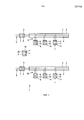
Фиг. 1 представляет собой схематическое и примерное изображение варианта осуществления системы распределения энергии постоянного тока,FIG. 1 is a schematic and example image of an embodiment of a DC power distribution system,
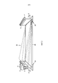
Фиг. 2 представляет собой изображение внешнего вида устройства связи системы распределения энергии постоянного тока по фиг. 1, иFIG. 2 is an external view of the communication device of the DC power distribution system of FIG. 1 and
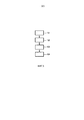
Фиг. 3 представляет собой блок-схему алгоритма, примерно показывающего способ связи, используемый с системой распределения энергии постоянного тока по фиг. 1.FIG. 3 is a flowchart illustrating approximately the communication method used with the direct current energy distribution system of FIG. one.
ПОДРОБНОЕОПИСАНИЕ ВАРИАНТОВ ОСУЩЕСТВЛЕНИЯDETAILED DESCRIPTION OF EMBODIMENTS
Согласно фиг. 1 в схематическом виде в качестве примера представлен вариант осуществления системы распределения энергии постоянного тока для распределения энергии постоянного тока. Система 1 распределения энергии постоянного тока содержит несколько рельсов 2 для распределения энергии постоянного тока, причем рельсы 2 выполнены с возможностью обеспечения связи по линиям электропередачи. Рельсы 2 предпочтительно являются компонентами токопроводящей шины, согласно требованиям стандарта EMerge. Также система 1 распределения энергии постоянного тока включает в себя источники 5 энергии для подачи энергии постоянного тока на рельсы 2 и электрические нагрузки 9, 10, соединенные с рельсами 2 для приема энергии постоянного тока. Также к рельсам 2 присоединены устройства 11 связи, которые выполнены с возможностью: приема беспроводным образом сигналов связи и передачи принятых сигналов связи посредством связи по линиям электропередачи на источники 5 энергии и/или электрические нагрузки 9, 10, и/или б) приема сигналов связи посредством связи по линиям электропередачи с источников 5 энергии и/или электрических нагрузок 9, 10 и передачи принятых сигналов связи беспроводным образом.According to FIG. 1 is a schematic view illustrating, as an example, an embodiment of a DC energy distribution system for distributing DC energy. The direct current energy distribution system 1 comprises
Система 1 распределения энергии постоянного тока также включает в себя блок 19 управления для управления источниками 5 энергии и/или электрическими нагрузками 9, 10; блок 19 управления выполнен с возможностью передавать беспроводным образом управляющие сигналы в виде сигналов связи на устройства 11 связи; причем устройства 11 связи выполнены с возможностью передачи сигналов связи на источники 5 энергии и/или электрические нагрузки 9,10 посредством соответствующей связи по линиям электропередачи для управления источниками 5 энергии и/или электрическими нагрузками 9,10. Система 1распределения энергии постоянного тока, в частности устройства 11 связи, обеспечивает таким образом гибридное решение управления по силовым линиям и беспроводным образом. Блок 19 управления можно выполнить с возможностью быть переключателем для переключения источников 5 энергии и/или электрических нагрузок 9,10.The DC power distribution system 1 also includes a
В данном варианте осуществления система 1 распределения энергии постоянного тока включает в себя как минимум два рельса 2 для распределения энергии постоянного тока, которые выполнены с возможностью обеспечивать связь по линиям электропередачи, и к каждому из этих по меньшей мере двух рельсов 2 подключено устройство 11 связи. Устройства 11 связи выполнены с возможностью передачи беспроводным образом сигналов связи между рельсами 2 и передачи сигналов связи посредством связи по линиям электропередачи, обеспечиваемой соответствующим рельсом 2.In this embodiment, the direct current energy distribution system 1 includes at least two
Устройства 11 связи являются отдельными элементами, то есть в данном варианте осуществления они не интегрированы в источники 5 энергии или электрические нагрузки 9,10. Кроме того, устройства 11 связи выполнены с возможностью крепления на рельсах 2, как в качестве примера показано в схематическом виде на фиг. 2.
Как показано на фиг. 2, система 1 распределения энергии постоянного тока предпочтительно интегрируется с подвесным потолком; причем подвесной потолок содержит плитки 24 потолка, закрепленные на выступах 23 несущих элементов 22 на рельсах 2. Рельс 2 включает в себя электрические проводники 3,4, которые можно считать проводниками токопроводящей шины, для распределения энергии постоянного тока, обеспечиваемой источниками 5 энергии. Эти электрические проводники 3,4 также служат для обеспечения связи по линиям электропередачи. Устройство 11 связи прикрепляется к верхней части соответствующего рельса 2, тем самым охватывая электрические проводники 3,4. Устройство 11 связи имеет закругленную внешнюю поверхность, а именно скругленные внешние боковые стенки, которые закруглены так, что будучи в рабочем положении, ширина устройства 11 связи в плоскости, перпендикулярной электрическим проводникам 3,4, уменьшается по мере уменьшения расстояния до выступов 23 несущего элемента 22. Это позволяет свободно, не задевая устройство 11 связи, устанавливать или удалять плитки 24 потолка, как показано на фиг. 2, при различных позициях 25 плитки потолка.As shown in FIG. 2, the DC power distribution system 1 is preferably integrated with a false ceiling; moreover, the suspended ceiling contains
Источники 5 энергии включают в себя преобразователь 7 для преобразования энергии сети переменного тока, принимаемой через электрические проводники 6 от питающей сети, в энергию постоянного тока, которая должна подаваться на электрические проводники 3,4 рельсов 2. Источники 5 энергии также включают в себя приемопередатчики 8 сигнала связи для приема и отправки сигналов связи, причем приемопередатчики 8 сигнала связи дополнительно выполнены с возможностью модулировать и демодулировать сигналы в целях преобразования команд связи по линиям электропередачи, в команды, которые исполняются источниками 5 энергии, а также для генерации команд связи по линиям электропередачи, которые должны отправляться посредством связи по линиям электропередачи.The
Электрические нагрузки 9 представляют собой светильники, снабженные приемопередатчиками 8 сигналов связи и источниками 13 света. Источники 13 света предпочтительно содержат задающую схему (схему драйвера) для управления характеристиками света, такими как интенсивность света и/или цвет светового пучка, испускаемого источником 13 света, причем управление задающей схемой может выполняться в зависимости от управляющих сигналов, принимаемых и демодулируемых приемопередатчиком 8 сигналов связи. Электрические нагрузки 9 электрически соединены с электрическими проводниками 3,4 через электрические соединители 18. Также электрические нагрузки 10 и устройства 11 связи электрически соединены с электрическими проводниками 3,4 через электрические соединители 18.
Электрические нагрузки 10 также содержат приемопередатчики 8 сигналов связи. Помимо этого, в данном варианте осуществления электрические нагрузки 10 содержат средство 15 кондиционирования воздуха, управляемое с помощью управляющих сигналов, принимаемых и демодулируемых приемопередатчиками 8 сигналов связи.
Блок 19 управления зафиксирован на стенке помещения, на потолке которого размещена система 1 распределения энергии постоянного тока. Блок 19 управления включает в себя блок 21 ввода для ввода пользователем входной управляющей информации для управления электрическими нагрузками 9, 10 и/или источниками 5 энергии. Блок 19 ввода может быть клавиатурой, вращающимся тумблером, сенсорным экраном и так далее. Блок 19 управления также содержит блок 20 отправки для преобразования входной управляющей информации в управляющие сигналы и отправки управляющих сигналов беспроводным образом на устройство 11 связи. Устройство 11 связи содержит блоки 17 отправки и приема для приема управляющих сигналов от блока 19 управления и преобразователей 16 сигналов для преобразования принятых беспроводным образом сигналов в сигналы связи по линиям электропередачи, и для передачи преобразованных сигналов связи по линиям электропередачи через электрические проводники 3, 4рельсов 2. Таким образом источниками 5 энергии и/или электрическими нагрузками 9,10 можно управлять с помощью блока 19 управления через устройства 11 связи.The
Преобразователи 16 сигналов также выполнены с возможностью преобразования сигналов связи по линиям электропередачи, принимаемых от электрических проводников 3, 4 рельсов 2 в беспроводные сигналы, которые затем отправляются с помощью блоков 17 отправки и приема на другие устройства 11 связи и/или блок 19 управления. В последнем случае блок 20 отправки блока 19 управления также выполнен с возможностью приема беспроводных сигналов. Принимаемые сигналы могут указывать информацию, например, о текущем и предыдущем статусе светильников и/или устройств кондиционирования воздуха; причем блок управления может содержать блок вывода, такой как дисплей, для отображения этой информации, или блок управления может отправлять эту информацию на следующее устройство, такое как система управления помещением или такое как отдельное устройство вывода, для вывода этой информация. Если в одном из вариантов осуществления по меньшей мере одна из электрических нагрузок, присоединенных к рельсу, представляет собой датчик, например датчик присутствия для определения присутствия человека в помещении, то блок управления может быть выполнен с возможностью принимать соответствующие беспроводные сигналы считывания и отправлять в ответ сигналы управления на светильник для управления светильником, в зависимости от принятого сигнала присутствия. Так, например, если принятый сигнал присутствия указывает, что человек находится в помещении, то блок управления может послать управляющие сигналы на светильник с тем, чтобы увеличить интенсивность освещения светильником, и, в частности, чтобы включить свет в помещении. Если, в одном из вариантов осуществления, система распределения энергии постоянного тока содержит датчик светового потока для измерения светового потока в помещении, например возле окна помещения, то блок управления может быть выполнен с возможностью принимать сигналы светового потока, которые указывают измеренный световой поток в помещении, и посылать управляющие сигналы на светильник, в зависимости от того, какой световой поток был указан с помощью принятых сигналов светового потока. В таком варианте светильниками можно управлять таким образом, чтобы интенсивность света, генерируемого светильником, увеличивалась, если измеренный световой поток уменьшился.
Таким образом, в данном варианте осуществления устройства 11 связи выполнены с возможностью только а) беспроводным образом принимать сигналы связи и передавать принятые сигналы связи через соответствующую связь по линиям электропередачи и/или б) принимать сигналы связи через соответствующую связь по линиям электропередачи и беспроводным образом передавать принятые сигналы связи. Следовательно, устройства 11 связи могут быть выполнены с возможностью только передачи принятых сигналов связи без участия интеллектуальной схемы.Thus, in this embodiment, the
Устройства 11 связи выполнены с возможностью снабжения энергией постоянного тока, распределяемой через рельсы 2. Однако устройства связи могут также содержать устройства хранения энергии, например батарею или супер-конденсатор для питания устройств связи. Кроме того, устройства связи могут быть переключаемыми. Так, например, они могут принимать переключающие сигналы от, например, блока 19 управления, так что устройства 11 связи могут быть включены или выключены с помощью блока 19 управления.The
Ниже вариант осуществления способа связи для использования применительно к системе 1 распределения энергии постоянного тока, будет описан на примере блок-схемы, приведенной на фиг. 3.Below, an embodiment of a communication method for use with respect to a direct current energy distribution system 1 will be described using the flowchart shown in FIG. 3.
На этапе 101 блок 19 управления беспроводным образом отправляет управляющие сигналы на устройства 11 связи. На этапе 102 устройства 11 связи принимают управляющие сигналы и преобразовывают принятые беспроводным образом управляющие сигналы в управляющие сигналы связи по линиям электропередачи. На этапе 103 преобразованные управляющие сигналы связи по линиям электропередачи передаются на источники 5 энергии и/или электрические нагрузки 9, 10посредством связи по линиям электропередачи, обеспечиваемой рельсами 2, а на этапе 104 производится управление источниками 5 энергии и/или электрическими нагрузками 9, 10, в зависимости от переданных управляющих сигналов связи по линиям электропередачи.In
Преимуществом связи по линиям электропередачи является то, что она очень надежна по сравнению со связью в обычно перегруженном беспроводном спектре. Кроме того, связь по линиям электропередачи позволяет более естественным образом и в автоматическом режиме группировать устройства по их соответствующему физическому местоположению и, в основном, по их соответствующему питанию, если один или несколько рельсов, подключенных к источнику энергии, имеют раздельные каналы связи по линиям электропередачи. Так, например, показанные на фиг. 2 электрические нагрузки 9,10, присоединенные к одному и тому же рельсу 2, могут автоматически образовывать группу устройств.The advantage of power line communications is that it is very reliable compared to communications in a typically congested wireless spectrum. In addition, communication via power lines allows for more natural and automatic mode to group devices according to their respective physical location and, basically, according to their respective power supply, if one or more rails connected to the energy source have separate communication channels over power lines . So, for example, shown in FIG. 2,
Связь по линиям электропередачи, то есть соответствующий интерфейс связи по линиям электропередачи, может использовать хорошо известные технологии связи, например технологии связи с высокой пропускной способностью, такой как технология на основе HomePlug, или технологии связи с невысокой пропускной способностью. Связь по линиям электропередачи может использовать серийные протоколы или протоколы с коллективно используемой средой, и может конфигурацию типа «ведущий-ведомый» или другого типа. Кроме того, связь по линиям электропередачи различных рельсов может быть разделена, то есть каждый рельс может иметь свой собственный канал связи по линиям электропередачи, или, несколько рельсов могут быть объединены так, чтобы они использовали один и тот же канал связи по линиям электропередачи. Так, например, если несколько рельсов подключены к одному и тому же источнику энергии, то эти рельсы могут иметь общий канал связи по линиям электропередачи.Power line communications, that is, the corresponding power line communications interface, can utilize well-known communication technologies, for example, high bandwidth communication technologies such as HomePlug based technology, or low bandwidth communication technologies. Power line communications may use serial protocols or shared media protocols, and may have a master-slave configuration or another type of configuration. In addition, the communication on the power lines of various rails can be divided, that is, each rail can have its own communication channel on the power lines, or several rails can be combined so that they use the same communication channel on the power lines. So, for example, if several rails are connected to the same energy source, then these rails may have a common communication channel over power lines.
Использованная беспроводная связь, т.е. использованный интерфейс беспроводной связи, может быть основана на любой хорошо известной беспроводной технологии, например технологии радиосвязи, технологии беспроводной связи с низкой пропускной способностью, технологии беспроводной связи с высокой пропускной способностью, беспроводной технологии в соответствии со стандартной или проприетарной беспроводной технологией, беспроводной технологии с использованием ячеистой топологии или другой топологии и так далее. Так, например, беспроводная связь может использовать Wi-Fi, ZigBee, BT, 6LoWPAN, и так далее. Могут также быть использованы другие виды беспроводной связи, например технологии, основанные на приеме/передаче аудиосигнала, или испускании/обнаружении светового сигнала.Used wireless, i.e. used wireless communication interface can be based on any well-known wireless technology, for example, radio technology, low-bandwidth wireless technology, high-bandwidth wireless technology, wireless technology in accordance with standard or proprietary wireless technology, wireless technology using mesh topology or other topology and so on. For example, wireless can use Wi-Fi, ZigBee, BT, 6LoWPAN, and so on. Other types of wireless communications may also be used, for example, technologies based on receiving / transmitting an audio signal or emitting / detecting a light signal.
Беспроводная технология особенно полезна в тех случаях, когда те устройства, которые должны связываться с устройствами, присоединенными к рельсу, размещены вне потолочного перекрытия. В частности, беспроводная технология особенно полезна, если для отправки управляющих сигналов на присоединенные к рельсу устройства используется блок управления, например настенный переключатель, который был описан выше в соответствии с фиг. 1, настенный или настольный блок дистанционного управления, портативные устройства типа смартфона или планшета, выполненные с возможностью управления присоединенными к рельсу устройствами, и т.д.. Управляющее устройство, такое как блок 19 управления, описанный выше в соответствии с фиг. 1, а в частности блок 20 отправки, предпочтительно содержит антенну для беспроводной отправки и опционально для приема сигналов связи. Блоки 17 отправки и приема устройств связи также имеют антенны для беспроводной отправки и приема сигналов связи.Wireless technology is especially useful when those devices that need to communicate with devices attached to the rail are placed outside the ceiling. In particular, wireless technology is particularly useful if a control unit is used to send control signals to devices connected to the rail, for example a wall switch, which was described above in accordance with FIG. 1, a wall-mounted or desktop remote control unit, portable devices such as a smartphone or tablet, configured to control devices attached to the rail, etc. A control device, such as the
В системе распределения энергии постоянного тока, описанной выше в соответствии с фиг. 1, связь не обрывается на каком-то определенном рельсе. С помощью устройств 11 связи, которые можно считать зажимами для ввода, устанавливается связь между рельсами. За счет этого организуется связь между закрепленными элементами, то есть электрическими нагрузками, присоединенными к отдельным рельсам. Гибридная связь по беспроводному каналу и линиям электропередачи, также позволяет устанавливать связь между электрическими нагрузками, присоединенными к потолочному перекрытию, то есть присоединенными к рельсам, и устройствами, которые не закреплены на потолочном перекрытии, например настенным переключателем. Для того, чтобы такая связь состоялась, в устройства связи встроены оба интерфейса связи: интерфейс беспроводной связи и интерфейс связи по линиям электропередачи. Они лучше всего приспособлены для пересылки сообщений, в частности выбранных сообщений, принятых с одного интерфейса, на другой интерфейс, в результате чего производится разъединение каналов связи и создается одна гибридная система управления. Закрепленные элементы, такие как электрические нагрузки 9,10 и/или источники энергии, и/или другие электрические нагрузки на потолочной сборке, например точки доступа, также могут быть выполнены с возможностью обеспечения функции гибридного управления; при этом устройства связи могут быть интегрированы в вышеприведенные устройства в составе потолочной сборки.In the DC power distribution system described above in accordance with FIG. 1, the connection does not break on any particular rail. Using the
Устройства связи могут конструктивно быть достаточно простыми устройствами, способными пересылать любой сигнал связи, принятый через беспроводной интерфейс или интерфейс связи по линиям электропередачи, и при этом они могут исполнять функции как однонаправленного, так и реверсивного ретранслятора. Однако эти устройства связи могут также включать в себя схемы для пересылки трафика, то есть сигналов связи, только на выбранные устройства и/или только на другие выбранные устройства связи, которые можно рассматривать как шунты. Устройства связи также могут быть выполнены с возможностью отправки определенных сигналов связи, которые были приняты через один из интерфейсов, через тот же самый интерфейс с или без отправки принятого сигнала связи через другой интерфейс. В большинстве случаев устройства могут содержать правилу пересылки, задающие, какой тип сигнала связи на какие устройства, в частности на какую нагрузку или на какой источник энергии, и через какой из интерфейсов связи нужно послать. Так, например, устройства связи могут быть выполнены с возможностью: а) приема беспроводным образом сигналов связи и передачи принятых сигналов связи посредством связи по линиям электропередачи, и/или б) приема сигналов связи посредством связи по линиям электропередачи и передачи принятых сигналов связи беспроводным образом в соответствии с правилом пересылки.Communication devices can be structurally simple enough devices that can send any communication signal received via a wireless interface or a communication interface via power lines, and at the same time they can perform the functions of either a unidirectional or a reverse repeater. However, these communication devices may also include circuits for sending traffic, that is, communication signals, only to selected devices and / or only to other selected communication devices, which can be considered as shunts. Communication devices can also be configured to send certain communication signals that have been received through one of the interfaces, through the same interface with or without sending a received communication signal through another interface. In most cases, devices can contain a forwarding rule that specifies which type of communication signal to which devices, in particular to which load or to which energy source, and through which of the communication interfaces it is necessary to send. So, for example, communication devices can be configured to: a) wirelessly receive communication signals and transmit received communication signals through communication via power lines, and / or b) receive communication signals through communication via power lines and transmit received communication signals wirelessly in accordance with the forwarding rule.
Функция шунтирования, то есть создание мостика между интерфейсом связи по линиям электропередачи и интерфейсом беспроводной связи, может быть управляемой, то есть устройства связи можно переключать так, что интерфейс связи по линиям электропередачи и интерфейс беспроводной связи может быть включен или отключен. Переключение можно сделать автоматическим, например с помощью процедуры самораспознавания, выполняемой устройствами связи, или ручным с помощью аппаратных средств или через линии электропередачи или беспроводную связь, причем в последнем случае переключающий сигнал можно посылать на устройства связи с использованием блока управления или другого устройства. Переключение устройств связи производится в процессе конфигурирования/запуска в эксплуатацию системы распределения энергии постоянного тока, в ходе эксплуатации системы распределения энергии постоянного тока и так далее. Кроме того, автоматическое переключение устройств связи может производиться в зависимости от статуса оборудования, объема передаваемой информации или условий формирования погрешностей в рельсе. В одном варианте осуществления изобретения электрическая нагрузка, присоединенная к рельсу, выполнена с возможностью отправлять сигналы связи по линиям электропередачи на устройство связи с тем, чтобы включать устройство связи, если от электрической нагрузки требуется выполнение функции связи.The bypass function, that is, the bridge between the power line communication interface and the wireless interface, can be controlled, that is, the communication device can be switched so that the power line communication interface and the wireless interface can be turned on or off. Switching can be done automatically, for example, using a self-recognition procedure performed by communication devices, or manually using hardware or via power lines or wireless communications, in which case the switching signal can be sent to communication devices using a control unit or other device. Switching of communication devices is performed during the configuration / commissioning of the DC power distribution system, during the operation of the DC power distribution system, and so on. In addition, automatic switching of communication devices can be made depending on the status of the equipment, the amount of transmitted information or the conditions for the formation of errors in the rail. In one embodiment of the invention, an electrical load attached to the rail is configured to send communication signals via power lines to the communication device so as to turn on the communication device if the communication function is required from the electrical load.
Правила пересылки, которые можно считать как задающие функции пересылки и фильтрации, можно заранее конфигурировать или выполнять их конфигурирование на этапе ввода в эксплуатацию и/или в процессе эксплуатации. Так, например, правила пересылки можно конфигурировать посредством электрических нагрузок, присоединенных к рельсам; причем электрические нагрузки могут быть выполнены с возможностью запрашивать выполнение определенных функциональных возможностей связи у устройства связи. Так, например, электрическая нагрузка может быть выполнена с возможностью запрашивать устройства связи об отправке сигналов связи по линиям электропередачи от электрической нагрузки только на конкретные другие устройства, или принимать с устройства связи только конкретные типы сигналов, или принимать сигналы только со конкретных устройств. Кроме того, устройство связи может быть выполнено с возможностью иметь список устройств, с которыми оно связано по линиям электросети, а правила пересылки могут задавать, что принятые беспроводным способом сигналы должны отправляться только по каналу связи по линиям электропередачи в том случае, если они адресованы устройствам, включенным в список. Данный список можно создать заранее, в частности, его может создать вручную специалист по установке, но он также может быть составлен и в дальнейшем модифицироваться самим устройством связи, а присоединенные электрические нагрузки и/или источники энергии могут быть выполнены с возможностью отправки идентификационного сигнала связи по линиям электропередачи на устройство связи, чтобы позволить устройству связи добавить присоединенные электрические нагрузки и/или источники энергии в список.Forwarding rules, which can be considered as defining the forwarding and filtering functions, can be preconfigured or configured at the commissioning stage and / or during operation. For example, forwarding rules can be configured by means of electrical loads attached to the rails; moreover, electrical loads can be performed with the ability to request the execution of certain communication functionality from the communication device. So, for example, an electric load can be configured to request communication devices to send communication signals from power lines to specific other devices only, or to receive only specific types of signals from a communication device, or to receive signals only from specific devices. In addition, the communication device can be configured to have a list of devices with which it is connected via power lines, and forwarding rules can specify that signals received wirelessly should be sent only via a communication channel via power lines if they are addressed to devices included in the list. This list can be created in advance, in particular, it can be created manually by the installation specialist, but it can also be compiled and further modified by the communication device itself, and the connected electrical loads and / or energy sources can be configured to send the communication identification signal via power lines to the communication device to allow the communication device to add connected electrical loads and / or energy sources to the list.
Устройства связи, которые можно также считать зажимами для ввода, легко присоединяются к рельсам, в роли которых в данном варианте осуществления выступают шины по стандарту EMerge, и имеют такой форм-фактор, что все еще обеспечивают простую установку и изъятие потолочных плиток. Другими словами, форм-фактор устройств связи выполнен так, что устройства связи не ограничивают перемещения потолочных плиток, при их установке на или удалении из выступа несущего элемента рельса. Функцию управления можно легко установить путем фиксации устройств связи на рельсах, что может обеспечивать независимые от производителя решения для передачи данных. Подключение функции связи выполняется относительно легко и может быть осуществлено после того, как все остальные компоненты системы распределения энергии постоянного тока были уже установлены. Устройства связи позволяют модернизировать решения обеспечивающие предоставление функции связи существующим системам распределения энергии постоянного тока. Так, функция связи дает возможность управляющей сети управлять отдельными устройствами, в частности электрическими нагрузками, или группами устройств.Communication devices, which can also be considered as input clamps, are easily connected to rails, which in this embodiment are EMerge standard buses, and have such a form factor that they still provide easy installation and removal of ceiling tiles. In other words, the form factor of the communication devices is such that the communication devices do not limit the movement of the ceiling tiles when they are installed on or removed from the protrusion of the rail bearing element. The control function can be easily installed by fixing communication devices on rails, which can provide manufacturer-independent data transmission solutions. Connection of the communication function is relatively easy and can be done after all other components of the DC energy distribution system have already been installed. Communication devices allow you to upgrade solutions that provide the communication function to existing DC energy distribution systems. So, the communication function enables the control network to control individual devices, in particular electrical loads, or groups of devices.
Несмотря на то, что в вышеописанных вариантах осуществления управляющие сигналы в основном передаются через устройство связи, через него можно передавать и другие сигналы, не являющиеся управляющими. Так, например, через устройство связи можно передавать сигналы, отображающие информацию, например, о статусе устройства, или сигналы другого типа.Despite the fact that in the above-described embodiments, control signals are mainly transmitted through a communication device, other non-control signals can be transmitted through it. So, for example, through a communication device, you can transmit signals that display information, for example, about the status of the device, or signals of another type.
Несмотря на то, что в вышеописанном варианте осуществления со ссылкой на фиг. 1 устройства связи являются отдельными от других устройств, например электрических нагрузок, присоединенных к рельсу, в других вариантах осуществления устройства связи могут быть интегрированы в источники энергии и/или электрические нагрузки.Although in the above embodiment, with reference to FIG. 1, communication devices are separate from other devices, for example, electrical loads attached to a rail, in other embodiments, communication devices can be integrated into energy sources and / or electrical loads.
Несмотря на то, что в вышеописанном варианте осуществления со ссылкой на фиг. 1 каждый из рельсов соединен с отдельным источником энергии, в других осуществлениях несколько рельсов могут быть соединены к одним и тем же источником энергии. Так, например, на фиг. 1 только один источник питания может быть электрически соединен с двумя рельсами.Although in the above embodiment, with reference to FIG. 1, each of the rails is connected to a separate energy source, in other implementations, several rails can be connected to the same energy source. For example, in FIG. 1, only one power source can be electrically connected to two rails.
Другие варианты осуществления данного изобретения станут понятными специалистам в данной области техники после изучения чертежей, описания изобретения и формулы изобретения.Other embodiments of the invention will become apparent to those skilled in the art upon examination of the drawings, description of the invention, and claims.
В формуле изобретения слово «содержит» не исключает другие элементы и этапы, а использование единственного числа для их обозначения не исключает множества.In the claims, the word “contains” does not exclude other elements and steps, and the use of the singular to designate them does not exclude a plurality.
Единственное устройство или блок могут выполнять функции нескольких устройств в формуле изобретения. Тот факт, что отдельные меры указаны в различных зависимых пунктах формулы, не свидетельствует о том, что эти меры нельзя использовать в сочетании для достижения наилучшего осуществления изобретения.A single device or block may fulfill the functions of several devices in the claims. The fact that individual measures are indicated in the various dependent claims does not indicate that these measures cannot be used in combination to achieve the best possible implementation of the invention.
Такие операции, как отправка и прием беспроводных сигналов и/или сигналов связи по линиям электропередачи, модуляция и демодуляция сигналов связи, генерация управляющих сигналов, основанных на управляющей информации, которые могут быть введены пользователем, и так далее, которые выполняются одним или несколькими блоками или устройствами, могут выполняться и другими блоками и устройствами в другом количестве. Эти операции, в частности функция гибридной связи по линиям электропередачи и беспроводному каналу, могут быть реализованы средством программного кода компьютерной программы и/или специализированными аппаратными средствами.Operations such as sending and receiving wireless and / or communication signals over power lines, modulating and demodulating communication signals, generating control signals based on control information that can be entered by the user, and so on, which are performed by one or more blocks or devices can be performed by other blocks and devices in a different quantity. These operations, in particular the function of hybrid communication over power lines and a wireless channel, can be implemented by means of program code of a computer program and / or specialized hardware.
Компьютерная программа может размещаться/распространяться на подходящем носителе, например оптическом запоминающем устройстве или твердотельном ЗУ, которые поставляются совместно или как часть другого оборудования, но могут распространяться и в другой форме, например по интернету или другой проводной или беспроводной системе связи.The computer program may be located / distributed on a suitable medium, such as optical storage device or solid state memory, which are supplied jointly or as part of other equipment, but may also be distributed in other forms, for example via the Internet or other wired or wireless communication system.
Любые условные обозначения, содержащиеся в пунктах формулы изобретения, не должны рассматриваться как ограничивающие его объем.Any conventions contained in the claims should not be construed as limiting its scope.
Изобретение относится к системе распределения энергии постоянного тока, в частности к системе распределения энергии постоянного тока, соответствующей стандарту EМerge, для распределения энергии постоянного тока. Источник питания подает энергию постоянного тока на рельс, к которому подключена электрическая нагрузка. К рельсу подсоединено устройство связи, которое а) беспроводным образом принимает сигналы связи и передает принятые сигналы связи посредством связи по линиям электропередачи, которую обеспечивает рельс, на источник энергии и/или электрическую нагрузку, и/или б) принимает сигналы связи посредством связи по линиям электропередачи от источника энергии и/или электрической нагрузки, и передает принятые сигналы связи беспроводным образом. Таким образом обеспечивается настройка связи, которая обеспечивает очень легкую интеграцию функциональной возможности управления для управления, например, источником энергии и/или электрической нагрузкой за счет передачи управляющих сигналов через устройство связи.The invention relates to a DC power distribution system, in particular to a DC energy distribution system in accordance with the EMerge standard, for direct current energy distribution. A power source supplies direct current energy to a rail to which an electrical load is connected. A communication device is connected to the rail, which a) wirelessly receives communication signals and transmits the received communication signals via communication via the power lines provided by the rail to a power source and / or electric load, and / or b) receives communication signals via communication on the lines power transmission from an energy source and / or electrical load, and transmits received communication signals wirelessly. In this way, a communication setting is provided that provides very easy integration of the control functionality for controlling, for example, an energy source and / or an electrical load by transmitting control signals via a communication device.
Claims (14)
Applications Claiming Priority (3)
| Application Number | Priority Date | Filing Date | Title |
|---|---|---|---|
| US201361803544P | 2013-03-20 | 2013-03-20 | |
| US61/803,544 | 2013-03-20 | ||
| PCT/IB2014/059609 WO2014147512A1 (en) | 2013-03-20 | 2014-03-11 | Dc power distribution system |
Publications (3)
| Publication Number | Publication Date |
|---|---|
| RU2015144900A RU2015144900A (en) | 2017-04-25 |
| RU2015144900A3 RU2015144900A3 (en) | 2018-03-19 |
| RU2672259C2 true RU2672259C2 (en) | 2018-11-13 |
Family
ID=50346060
Family Applications (1)
| Application Number | Title | Priority Date | Filing Date |
|---|---|---|---|
| RU2015144900A RU2672259C2 (en) | 2013-03-20 | 2014-03-11 | Dc power distribution system |
Country Status (7)
| Country | Link |
|---|---|
| US (1) | US9997958B2 (en) |
| EP (1) | EP2976825B1 (en) |
| JP (1) | JP6522582B2 (en) |
| CN (1) | CN105052007B (en) |
| BR (1) | BR112015023887A2 (en) |
| RU (1) | RU2672259C2 (en) |
| WO (1) | WO2014147512A1 (en) |
Families Citing this family (8)
| Publication number | Priority date | Publication date | Assignee | Title |
|---|---|---|---|---|
| US10141739B1 (en) * | 2015-05-26 | 2018-11-27 | The Watt Stopper, Inc. | System for distributing DC power to and controlling building devices |
| ES2751023T3 (en) * | 2015-11-26 | 2020-03-30 | Signify Holding Bv | A lighting module arranged to connect to a luminaire |
| JP6467387B2 (en) * | 2016-09-14 | 2019-02-13 | 矢崎総業株式会社 | Electrical unit |
| KR101995255B1 (en) * | 2017-10-24 | 2019-07-03 | 주식회사 윈텍오토메이션 | DC autonomous distribution control system for efficient power transmission and distribution between loads in a micro grid and its operation method |
| US10566801B2 (en) * | 2018-01-02 | 2020-02-18 | Juniper Networks, Inc | Apparatus, system, and method for preventing improper installation of power supply modules on network devices |
| US10648686B2 (en) * | 2018-05-15 | 2020-05-12 | Johnson Controls Technology Company | HVAC high voltage powerline communication systems and methods |
| TWI693512B (en) | 2018-11-16 | 2020-05-11 | 緯穎科技服務股份有限公司 | Server device and power management method thereof |
| IT202000003113A1 (en) * | 2020-02-17 | 2021-08-17 | Huna S R L | Luminaire and system for remote control of a lighting device through an electric power cable |
Citations (5)
| Publication number | Priority date | Publication date | Assignee | Title |
|---|---|---|---|---|
| US20060202851A1 (en) * | 2005-03-12 | 2006-09-14 | Cash Audwin W | Handheld programmer for lighting control system |
| WO2011112506A2 (en) * | 2010-03-08 | 2011-09-15 | Virticus Corporation | Method and system for automated lighting control and monitoring |
| DE202012100843U1 (en) * | 2011-03-17 | 2012-04-02 | Insta Elektro Gmbh | Control unit for controlling a at least one active lamp comprehensive lamp unit and lamp unit for it |
| RU2462004C2 (en) * | 2007-04-30 | 2012-09-20 | Конинклейке Филипс Электроникс Н.В. | Modular solid-state lighting system |
| RU2476038C2 (en) * | 2006-12-12 | 2013-02-20 | Конинклейке Филипс Электроникс Н.В. | System and method for illumination control |
Family Cites Families (25)
| Publication number | Priority date | Publication date | Assignee | Title |
|---|---|---|---|---|
| JPS5470665A (en) * | 1977-11-15 | 1979-06-06 | Matsushita Electric Works Ltd | Remote control type illumination control unit |
| JPH03102797A (en) * | 1989-09-14 | 1991-04-30 | Matsushita Electric Works Ltd | Wireless type illumination load control system |
| IT1310142B1 (en) * | 1999-08-20 | 2002-02-11 | Merloni Elettrodomestici Spa | DEVICE, SYSTEM AND METHOD FOR THE MONITORING OF A DOMESTIC ELECTRICITY USE, IN PARTICULAR A HOUSEHOLD APPLIANCE. |
| WO2004046477A2 (en) | 2002-09-04 | 2004-06-03 | Herman Miller, Inc. | Infrastructure system |
| US7045967B2 (en) * | 2003-07-16 | 2006-05-16 | Taipei Multipower Electronics Co., Ltd. | Multi-lamp actuating facility |
| JP4268859B2 (en) * | 2003-11-27 | 2009-05-27 | 株式会社日立製作所 | Airline lighting breakage position detector |
| DE102004002018A1 (en) | 2004-01-14 | 2005-08-04 | Tridonicatco Gmbh & Co. Kg | DC-supplied equipment modules for lamps |
| US7369060B2 (en) * | 2004-12-14 | 2008-05-06 | Lutron Electronics Co., Inc. | Distributed intelligence ballast system and extended lighting control protocol |
| DE102006033673A1 (en) * | 2006-07-20 | 2008-01-24 | Patent-Treuhand-Gesellschaft für elektrische Glühlampen mbH | Switchgear, system for controlling a lamp and lighting control system for a building with at least one luminaire |
| JP4821495B2 (en) * | 2006-08-10 | 2011-11-24 | パナソニック電工株式会社 | Power distribution system |
| US20080092075A1 (en) * | 2006-10-13 | 2008-04-17 | Joe Suresh Jacob | Method of building a database of a lighting control system |
| JP2009021951A (en) * | 2007-07-13 | 2009-01-29 | Toshiba Lighting & Technology Corp | Adapter and illuminator |
| JP2009140759A (en) * | 2007-12-06 | 2009-06-25 | Toshiba Lighting & Technology Corp | Lighting control system |
| JP2009158298A (en) * | 2007-12-26 | 2009-07-16 | Panasonic Electric Works Co Ltd | Hook ceiling |
| JP2010080102A (en) * | 2008-09-24 | 2010-04-08 | Toshiba Lighting & Technology Corp | Lighting control system |
| US8248230B2 (en) | 2009-02-20 | 2012-08-21 | Redwood Systems, Inc. | Smart power device |
| EP2417832B1 (en) * | 2009-04-09 | 2015-02-25 | Koninklijke Philips N.V. | Intelligent lighting control system |
| JP2011101529A (en) * | 2009-11-06 | 2011-05-19 | Panasonic Electric Works Co Ltd | Power distribution system |
| JP2011150859A (en) * | 2010-01-20 | 2011-08-04 | Panasonic Electric Works Co Ltd | Wiring system and conductive rail |
| US8432143B2 (en) | 2010-02-16 | 2013-04-30 | Femtogrid Energy Solutions B.V. | Electrically parallel connection of photovoltaic modules in a string to provide a DC voltage to a DC voltage bus |
| JP2011175782A (en) * | 2010-02-23 | 2011-09-08 | Panasonic Electric Works Co Ltd | Lighting fixture |
| KR20110121187A (en) | 2010-04-30 | 2011-11-07 | 최인숙 | Indoor dc power system capable of power line communication |
| EP2745634B1 (en) | 2011-08-17 | 2016-01-20 | Koninklijke Philips N.V. | Method and system for localisation on a dc lighting and power grid |
| EP2568769A1 (en) | 2011-09-12 | 2013-03-13 | Philips Intellectual Property & Standards GmbH | Electrical device and power grid system |
| JP6342412B2 (en) | 2012-11-26 | 2018-06-13 | フィリップス ライティング ホールディング ビー ヴィ | Signal level based control of power grid load systems |
-
2014
- 2014-03-11 WO PCT/IB2014/059609 patent/WO2014147512A1/en active Application Filing
- 2014-03-11 RU RU2015144900A patent/RU2672259C2/en not_active IP Right Cessation
- 2014-03-11 EP EP14712047.1A patent/EP2976825B1/en active Active
- 2014-03-11 US US14/778,376 patent/US9997958B2/en active Active
- 2014-03-11 BR BR112015023887A patent/BR112015023887A2/en not_active Application Discontinuation
- 2014-03-11 JP JP2016503740A patent/JP6522582B2/en not_active Expired - Fee Related
- 2014-03-11 CN CN201480017195.9A patent/CN105052007B/en active Active
Patent Citations (5)
| Publication number | Priority date | Publication date | Assignee | Title |
|---|---|---|---|---|
| US20060202851A1 (en) * | 2005-03-12 | 2006-09-14 | Cash Audwin W | Handheld programmer for lighting control system |
| RU2476038C2 (en) * | 2006-12-12 | 2013-02-20 | Конинклейке Филипс Электроникс Н.В. | System and method for illumination control |
| RU2462004C2 (en) * | 2007-04-30 | 2012-09-20 | Конинклейке Филипс Электроникс Н.В. | Modular solid-state lighting system |
| WO2011112506A2 (en) * | 2010-03-08 | 2011-09-15 | Virticus Corporation | Method and system for automated lighting control and monitoring |
| DE202012100843U1 (en) * | 2011-03-17 | 2012-04-02 | Insta Elektro Gmbh | Control unit for controlling a at least one active lamp comprehensive lamp unit and lamp unit for it |
Also Published As
| Publication number | Publication date |
|---|---|
| CN105052007A (en) | 2015-11-11 |
| RU2015144900A (en) | 2017-04-25 |
| BR112015023887A2 (en) | 2017-07-18 |
| EP2976825B1 (en) | 2019-01-09 |
| US9997958B2 (en) | 2018-06-12 |
| RU2015144900A3 (en) | 2018-03-19 |
| JP6522582B2 (en) | 2019-05-29 |
| US20160285309A1 (en) | 2016-09-29 |
| WO2014147512A1 (en) | 2014-09-25 |
| EP2976825A1 (en) | 2016-01-27 |
| CN105052007B (en) | 2019-02-26 |
| JP2016519558A (en) | 2016-06-30 |
Similar Documents
| Publication | Publication Date | Title |
|---|---|---|
| RU2672259C2 (en) | Dc power distribution system | |
| US20130202301A1 (en) | Illumination System | |
| US10517163B2 (en) | Power receptacle control circuitry | |
| US10785838B2 (en) | Indoor power line transmission control system | |
| CN104660331A (en) | Information sending, receiving method and device of terminal, and the terminal | |
| US10595381B2 (en) | Controlling power usage in appliances | |
| US10785854B2 (en) | Lighting system and lighting apparatus | |
| CN101958742A (en) | Relay forwarding control system and wireless control device for high current assembly | |
| US10725140B2 (en) | Operating of a transmission device of a lighting device comprising an illumination device | |
| EP3817514B1 (en) | Wireless lighting control system with automatic emergency mode exit network protocol | |
| US20140192679A1 (en) | Convergent Network Node with the Automatic Reconfiguration Capability | |
| CN104521098B (en) | DC power distribution system with power saving functionality | |
| CN108235523B (en) | Node controller and lamp control system using same | |
| US20160336797A1 (en) | Systems and methods for managing power sources for a plurality of luminaires | |
| US11506414B2 (en) | Intelligent low-voltage power delivery system and method | |
| KR102062660B1 (en) | Rail system with wireless control | |
| JP2011204412A (en) | Lighting control system | |
| CN214670121U (en) | Electronic ballast and intelligent home control system | |
| EP4340175A1 (en) | Rail for suspending electronic devices and system comprising such a rail and one or more electronic devices | |
| WO2024064019A1 (en) | Rail for suspending electronic devices and system comprising such a rail and one or more electronic devices | |
| KR20140145791A (en) | Dimming controlling system | |
| KR20110104136A (en) | A smps and lihgting control unit |
Legal Events
| Date | Code | Title | Description |
|---|---|---|---|
| MM4A | The patent is invalid due to non-payment of fees |
Effective date: 20200312 |