RU2669309C2 - Electrified rail, in particular, for powering metal shelving units and the way of its production - Google Patents
Electrified rail, in particular, for powering metal shelving units and the way of its production Download PDFInfo
- Publication number
- RU2669309C2 RU2669309C2 RU2014131109A RU2014131109A RU2669309C2 RU 2669309 C2 RU2669309 C2 RU 2669309C2 RU 2014131109 A RU2014131109 A RU 2014131109A RU 2014131109 A RU2014131109 A RU 2014131109A RU 2669309 C2 RU2669309 C2 RU 2669309C2
- Authority
- RU
- Russia
- Prior art keywords
- grooves
- guide
- wires
- longitudinal
- rail
- Prior art date
Links
- 239000002184 metal Substances 0.000 title claims abstract description 22
- 229910052751 metal Inorganic materials 0.000 title claims abstract description 22
- 238000004519 manufacturing process Methods 0.000 title claims abstract description 15
- 230000002093 peripheral effect Effects 0.000 claims abstract description 18
- 239000004033 plastic Substances 0.000 claims abstract description 17
- 229920003023 plastic Polymers 0.000 claims abstract description 17
- 239000000463 material Substances 0.000 claims abstract description 14
- 238000001125 extrusion Methods 0.000 claims abstract description 13
- 239000004721 Polyphenylene oxide Substances 0.000 claims abstract description 9
- 229920006380 polyphenylene oxide Polymers 0.000 claims abstract description 9
- 229920000515 polycarbonate Polymers 0.000 claims abstract description 8
- 238000010292 electrical insulation Methods 0.000 claims abstract description 7
- 239000004417 polycarbonate Substances 0.000 claims abstract description 7
- 230000000694 effects Effects 0.000 claims abstract description 6
- 238000003780 insertion Methods 0.000 claims abstract description 5
- 230000037431 insertion Effects 0.000 claims abstract description 5
- 239000002131 composite material Substances 0.000 claims abstract description 4
- 230000005489 elastic deformation Effects 0.000 claims abstract description 3
- 210000003739 neck Anatomy 0.000 claims abstract 5
- 239000003000 extruded plastic Substances 0.000 claims description 6
- 239000002390 adhesive tape Substances 0.000 claims description 4
- 239000000853 adhesive Substances 0.000 claims description 3
- 230000001070 adhesive effect Effects 0.000 claims description 3
- 238000001816 cooling Methods 0.000 claims description 3
- 230000003993 interaction Effects 0.000 claims description 2
- 230000014759 maintenance of location Effects 0.000 claims 1
- 230000015572 biosynthetic process Effects 0.000 abstract description 4
- 239000000126 substance Substances 0.000 abstract 1
- 239000004020 conductor Substances 0.000 description 19
- RYGMFSIKBFXOCR-UHFFFAOYSA-N Copper Chemical compound [Cu] RYGMFSIKBFXOCR-UHFFFAOYSA-N 0.000 description 6
- 238000000576 coating method Methods 0.000 description 5
- 239000003292 glue Substances 0.000 description 5
- 238000005452 bending Methods 0.000 description 4
- 239000011248 coating agent Substances 0.000 description 4
- 238000009413 insulation Methods 0.000 description 4
- 229910052802 copper Inorganic materials 0.000 description 3
- 239000010949 copper Substances 0.000 description 3
- -1 for example Substances 0.000 description 3
- 239000011810 insulating material Substances 0.000 description 3
- 230000003647 oxidation Effects 0.000 description 3
- 238000007254 oxidation reaction Methods 0.000 description 3
- PXHVJJICTQNCMI-UHFFFAOYSA-N Nickel Chemical compound [Ni] PXHVJJICTQNCMI-UHFFFAOYSA-N 0.000 description 2
- 238000005516 engineering process Methods 0.000 description 2
- 238000000034 method Methods 0.000 description 2
- 239000004800 polyvinyl chloride Substances 0.000 description 2
- 229920000915 polyvinyl chloride Polymers 0.000 description 2
- 238000003825 pressing Methods 0.000 description 2
- 230000035939 shock Effects 0.000 description 2
- 239000007787 solid Substances 0.000 description 2
- 239000004925 Acrylic resin Substances 0.000 description 1
- 229920000178 Acrylic resin Polymers 0.000 description 1
- 229920004142 LEXAN™ Polymers 0.000 description 1
- 239000004418 Lexan Substances 0.000 description 1
- 239000004425 Makrolon Substances 0.000 description 1
- 239000004727 Noryl Substances 0.000 description 1
- 229920001207 Noryl Polymers 0.000 description 1
- 239000004698 Polyethylene Substances 0.000 description 1
- 239000004743 Polypropylene Substances 0.000 description 1
- 230000005540 biological transmission Effects 0.000 description 1
- 238000005520 cutting process Methods 0.000 description 1
- 238000003745 diagnosis Methods 0.000 description 1
- 239000003989 dielectric material Substances 0.000 description 1
- 238000009422 external insulation Methods 0.000 description 1
- PCHJSUWPFVWCPO-UHFFFAOYSA-N gold Chemical compound [Au] PCHJSUWPFVWCPO-UHFFFAOYSA-N 0.000 description 1
- 229910052737 gold Inorganic materials 0.000 description 1
- 239000010931 gold Substances 0.000 description 1
- 238000010438 heat treatment Methods 0.000 description 1
- 238000009434 installation Methods 0.000 description 1
- 238000002955 isolation Methods 0.000 description 1
- 150000002739 metals Chemical class 0.000 description 1
- 229910052759 nickel Inorganic materials 0.000 description 1
- 239000000615 nonconductor Substances 0.000 description 1
- 238000013021 overheating Methods 0.000 description 1
- 230000035515 penetration Effects 0.000 description 1
- 229920000573 polyethylene Polymers 0.000 description 1
- 229920001155 polypropylene Polymers 0.000 description 1
- 239000003351 stiffener Substances 0.000 description 1
Images
Classifications
-
- H—ELECTRICITY
- H01—ELECTRIC ELEMENTS
- H01R—ELECTRICALLY-CONDUCTIVE CONNECTIONS; STRUCTURAL ASSOCIATIONS OF A PLURALITY OF MUTUALLY-INSULATED ELECTRICAL CONNECTING ELEMENTS; COUPLING DEVICES; CURRENT COLLECTORS
- H01R25/00—Coupling parts adapted for simultaneous co-operation with two or more identical counterparts, e.g. for distributing energy to two or more circuits
- H01R25/16—Rails or bus-bars provided with a plurality of discrete connecting locations for counterparts
- H01R25/164—Connecting locations formed by flush mounted apparatus
-
- A—HUMAN NECESSITIES
- A47—FURNITURE; DOMESTIC ARTICLES OR APPLIANCES; COFFEE MILLS; SPICE MILLS; SUCTION CLEANERS IN GENERAL
- A47F—SPECIAL FURNITURE, FITTINGS, OR ACCESSORIES FOR SHOPS, STOREHOUSES, BARS, RESTAURANTS OR THE LIKE; PAYING COUNTERS
- A47F11/00—Arrangements in shop windows, shop floors or show cases
-
- H—ELECTRICITY
- H01—ELECTRIC ELEMENTS
- H01R—ELECTRICALLY-CONDUCTIVE CONNECTIONS; STRUCTURAL ASSOCIATIONS OF A PLURALITY OF MUTUALLY-INSULATED ELECTRICAL CONNECTING ELEMENTS; COUPLING DEVICES; CURRENT COLLECTORS
- H01R13/00—Details of coupling devices of the kinds covered by groups H01R12/70 or H01R24/00 - H01R33/00
- H01R13/02—Contact members
- H01R13/03—Contact members characterised by the material, e.g. plating, or coating materials
- H01R13/035—Plated dielectric material
-
- H—ELECTRICITY
- H01—ELECTRIC ELEMENTS
- H01R—ELECTRICALLY-CONDUCTIVE CONNECTIONS; STRUCTURAL ASSOCIATIONS OF A PLURALITY OF MUTUALLY-INSULATED ELECTRICAL CONNECTING ELEMENTS; COUPLING DEVICES; CURRENT COLLECTORS
- H01R13/00—Details of coupling devices of the kinds covered by groups H01R12/70 or H01R24/00 - H01R33/00
- H01R13/40—Securing contact members in or to a base or case; Insulating of contact members
- H01R13/42—Securing in a demountable manner
- H01R13/436—Securing a plurality of contact members by one locking piece or operation
-
- H—ELECTRICITY
- H01—ELECTRIC ELEMENTS
- H01R—ELECTRICALLY-CONDUCTIVE CONNECTIONS; STRUCTURAL ASSOCIATIONS OF A PLURALITY OF MUTUALLY-INSULATED ELECTRICAL CONNECTING ELEMENTS; COUPLING DEVICES; CURRENT COLLECTORS
- H01R25/00—Coupling parts adapted for simultaneous co-operation with two or more identical counterparts, e.g. for distributing energy to two or more circuits
- H01R25/14—Rails or bus-bars constructed so that the counterparts can be connected thereto at any point along their length
-
- H—ELECTRICITY
- H01—ELECTRIC ELEMENTS
- H01R—ELECTRICALLY-CONDUCTIVE CONNECTIONS; STRUCTURAL ASSOCIATIONS OF A PLURALITY OF MUTUALLY-INSULATED ELECTRICAL CONNECTING ELEMENTS; COUPLING DEVICES; CURRENT COLLECTORS
- H01R4/00—Electrically-conductive connections between two or more conductive members in direct contact, i.e. touching one another; Means for effecting or maintaining such contact; Electrically-conductive connections having two or more spaced connecting locations for conductors and using contact members penetrating insulation
- H01R4/28—Clamped connections, spring connections
- H01R4/48—Clamped connections, spring connections utilising a spring, clip, or other resilient member
-
- H—ELECTRICITY
- H01—ELECTRIC ELEMENTS
- H01R—ELECTRICALLY-CONDUCTIVE CONNECTIONS; STRUCTURAL ASSOCIATIONS OF A PLURALITY OF MUTUALLY-INSULATED ELECTRICAL CONNECTING ELEMENTS; COUPLING DEVICES; CURRENT COLLECTORS
- H01R43/00—Apparatus or processes specially adapted for manufacturing, assembling, maintaining, or repairing of line connectors or current collectors or for joining electric conductors
-
- Y—GENERAL TAGGING OF NEW TECHNOLOGICAL DEVELOPMENTS; GENERAL TAGGING OF CROSS-SECTIONAL TECHNOLOGIES SPANNING OVER SEVERAL SECTIONS OF THE IPC; TECHNICAL SUBJECTS COVERED BY FORMER USPC CROSS-REFERENCE ART COLLECTIONS [XRACs] AND DIGESTS
- Y10—TECHNICAL SUBJECTS COVERED BY FORMER USPC
- Y10T—TECHNICAL SUBJECTS COVERED BY FORMER US CLASSIFICATION
- Y10T29/00—Metal working
- Y10T29/49—Method of mechanical manufacture
- Y10T29/49002—Electrical device making
- Y10T29/49117—Conductor or circuit manufacturing
- Y10T29/49174—Assembling terminal to elongated conductor
- Y10T29/49181—Assembling terminal to elongated conductor by deforming
Landscapes
- Engineering & Computer Science (AREA)
- Manufacturing & Machinery (AREA)
- Installation Of Indoor Wiring (AREA)
- Details Of Indoor Wiring (AREA)
- Elimination Of Static Electricity (AREA)
Abstract
Description
Данное изобретение классифицируется в соответствии с международными классами H01R и G09F, и относится к электрифицированной направляющей, в частности для металлических стеллажей, которые оснащены с лицевой стороны полок, содержащих товары, электронными этикетками, дисплеями и/или другими периферийными устройствами. Более того, данное изобретение относится к способу производства такой электрифицированной направляющей.This invention is classified in accordance with the international classes H01R and G09F, and relates to an electrified rail, in particular for metal racks that are equipped on the front side of shelves containing goods, electronic labels, displays and / or other peripheral devices. Moreover, the present invention relates to a method for producing such an electrified rail.
В качестве существующего уровня техники приводятся следующие документы.As an existing prior art, the following documents are provided.
Патентная заявка WO 1994/22125 «система направляющих для отображения информации» описывает экструдированную направляющую с С-образным профилем, установленную на передней стороне полок. Направляющая имеет продольное верхнее ребро, в которое помещено электроизоляционное основание, несущее продольно установленные питаемые провода, помещенные на подходящем расстоянии друг от друга. Провода прикреплены к указанному основанию клеем примерно 180° их сечения и выступают по направлению вниз оставшимися свободными концами, с которыми подпружиненные концы электронных этикеток, предназначенные для крепления в указанную направляющую, могут входить в контакт.Patent application WO 1994/22125 "a system of guides for displaying information" describes an extruded guide with a C-shaped profile mounted on the front side of the shelves. The guide has a longitudinal upper rib, in which an electrical insulating base is placed, bearing longitudinally mounted feed wires placed at a suitable distance from each other. The wires are attached to the indicated base with glue of approximately 180 ° of their cross-section and protrude downward with the remaining free ends, with which the spring-loaded ends of electronic labels intended for fastening into the specified guide can come into contact.
Патент US 5348485 «Система отображения цен с вертикальной направляющей» также опубликованный в 1994 г., описывает систему соединения посредством электрических проводов и разъемов электрифицированных направляющих, размещенных на передней части полок для демонстрации товаров, на которых прикреплены электронные этикетки, с вертикальной электрифицированной направляющей, прикрепленной на стойках этого же стеллажа. Направляющая выполнена из экструдированной рейки, внутри которой прикреплены электропроводные металлические полосы, с помещением между ними электроизоляционного основания, металлическая полоса прикреплена посредством клея. Открытая поверхность металлической полосы соприкасается с гибкими подпружиненными электрическими контактами концевых разъемов указанных контактных проводов, указанные разъемы прикреплены на указанной вертикальной направляющей, электрические проводники которых соединены верхним концом с приспособлениями, помещенными на верхней части стеллажа, приспособлениями, обеспечивающими питание и управление указанными электронными этикетками.US 5,348,485, “Vertical Rail Price Display System” also published in 1994, describes a system for connecting electrical wires and connectors of electrified rails on the front of the shelves to display products on which electronic labels are attached, with a vertical electrified rail attached on racks of the same rack. The guide is made of extruded lath, inside of which electrically conductive metal strips are attached, with an insulating base placed between them, the metal strip is attached with glue. The open surface of the metal strip is in contact with the flexible spring-loaded electrical contacts of the terminal connectors of the indicated contact wires, these connectors are attached to the specified vertical rail, the electrical conductors of which are connected by the upper end to devices placed on the upper part of the rack, devices that provide power and control of the indicated electronic labels.
Французский патент FR 2765018 «Система отображения электронных этикеток», поданный в 1997 г., описывает электрифицированную направляющую, изготовленную из экструдированной пластиковой рейки, имеющей С-образный профиль, на нижней части которой по всей длине прикреплено электроизоляционное основание, на котором в продольном направлении прикреплены с помощью клея металлические полосы. Указанные металлические полосы одним концом соединены с приспособлениями, обеспечивающими питание и/или управление, тогда как направляющая профилирована так, чтобы закрепить электронную этикетку, имеющую на задней стороне подпружиненные контакты, соприкасающиеся с указанными металлическими полосами, обеспечивая необходимое соединение электронной этикетки и с приспособлениями удаленного питания и управления.French patent FR 2765018 "Electronic label display system", filed in 1997, describes an electrified guide made of an extruded plastic rail having a C-shaped profile, on the lower part of which an electrical insulating base is attached along the entire length, on which are longitudinally attached using glue metal stripes. These metal strips are connected at one end to devices that provide power and / or control, while the guide is profiled so as to fix an electronic label having spring-loaded contacts on the back that are in contact with these metal strips, providing the necessary connection for the electronic label and to remote power devices and management.
Патент Великобритании 1273670 (А) описывает рейку электропитания, включающую удлиненную металлическую опору, присоединенную с помощью кронштейнов к стене или потолку, гибкую полосу изоляционного материала, удерживаемого в опоре с помощью фланцев, и металлические проводники. Полоса оснащена канавками, в которых помещаются проводники, когда она ровная, но которая удерживает проводники, когда полоса изгибается вокруг своей продольной оси. Полоса также имеет углубления и/или возвышения между проводниками.British Patent 1273670 (A) describes a power rail, including an elongated metal support connected by brackets to a wall or ceiling, a flexible strip of insulating material held in support by flanges, and metal conductors. The strip is equipped with grooves in which the conductors are placed when it is flat, but which holds the conductors when the strip bends around its longitudinal axis. The strip also has recesses and / or elevations between the conductors.
Патент США 2,234,745 (А) описывает электрическое соединительное устройство, включающее направляющую, образованную из гибкого диэлектрического материала, такого, как например, резина. Оно имеет основание с фланцами, при помощи которых устройство может крепиться в своем положении. Две расположенных с интервалом канавки, разделенных расположенным по центру ребром, проходят через устройство и отверстие в верхнем его конце. Расположение канавок и следовательно ширина ребра являются такими, чтобы канавки вместили штыри разъема. Внешние стенки находятся на направляющей и во внутренней поверхности каждой из этих стенок образована полукруглая канавка, в каждой из которых установлена одна из электрических шин, изготовленных из гибкого провода свернутого в форме спирали. При сборке электрических шин в направляющей шины могут быть продвинуты в продольном направлении в канавки, при этом слегка разъединяя стенки так, чтобы позволить прижать шины в канавки до тех пор, пока они не разместятся напротив полукруглых канавок, после чего они встанут на свое место и будут устойчиво удерживаться на месте.US Pat. No. 2,234,745 (A) describes an electrical connection device including a guide formed of a flexible dielectric material, such as, for example, rubber. It has a base with flanges, with which the device can be mounted in its position. Two spaced grooves, separated by a centrally located rib, pass through the device and the hole at its upper end. The location of the grooves and therefore the width of the ribs are such that the grooves accommodate the pins of the connector. The outer walls are located on the guide and in the inner surface of each of these walls a semicircular groove is formed, in each of which one of the busbars made of flexible wire coiled in the form of a spiral is installed. When assembling the busbars in the guide rail, they can be advanced longitudinally into the grooves, while slightly separating the walls so as to allow the tires to be pressed into the grooves until they fit opposite the semicircular grooves, after which they snap into place and hold steady in place.
Существующий уровень техники, известный в данной области техники, имеет следующие недостатки:The current level of technology known in the art has the following disadvantages:
В отношении электрических проводников всех направляющих, будь они в форме проводов или полос, часть их поверхности, которая не прикреплена к опорному изоляционному материалу, является видимой и легко доступна пальцам человека, вызывая тем самым проблемы безопасности и для человека, и для электронных этикеток, контакты которых могут быть повреждены электростатическими ударами в результате случайного соприкосновения.With regard to the electrical conductors of all guides, whether they are in the form of wires or strips, a part of their surface that is not attached to the supporting insulating material is visible and easily accessible to the fingers of a person, thereby causing security problems for both the person and the electronic labels, contacts which can be damaged by electrostatic shock as a result of accidental contact.
Еще одним недостатком существующего уровня техники является низкая надежность крепления электрических проводников к опорной направляющей с помощью клея, свойства которого склонны меняться со временем из-за того, что электрические проводники испытывают нагрев благодаря эффекту Джоуля. Для решения данной проблемы может быть использован патент US 5890918, который описывает, как выполнить электрифицированную направляющую с использованием экструдированного корпуса из твердого материала, также проводящего электричество, с обеспечением указанного корпуса продольным пазом с круговым сечением, открытым наружу частью менее 180° его сечения. В указанный паз с нажимом вставляется медный провод, провод изолируется посредством оплетки из пластикового материала, имея внешний диаметр равный диаметру указанного паза, так что тот же провод может быть вставлен с нажимом и оставаться удерживаемым с трением в указанном пазу, который охватывает его на более чем 180° его внешней электроизоляционной оплетки. Данное решение включает использование точечных контактов на разъемах и периферийных устройствах; точечный контакт должен быть способен прокалывать изоляцию провода и соприкоснуться с тем же медным проводом для установления необходимого электрического контакта. Данное решение также имеет очень высокое сопротивление контакта из-за ограниченного поверхностного контакта между точечными контактами и проводниковым проводом. Техника прокола изоляции требует значительного усилия для того, чтобы точечный контакт проколол изоляцию провода и соприкоснулся с самим проводом, деформируя его, чтобы обеспечить эффективный контакт. В патенте US 5890918 указанное усилие достигается с помощью привинчиваемого контакта в соответствующем гнезде электрифицированной направляющей. Если считать, что каждый контакт должен иметь свою собственную электрическую изоляцию и прочный резьбовой корпус для обеспечения прочного крепления в гнезде электрической направляющей, например, три или четыре электрических проводника, можно с легкостью понять, что уменьшение размера электрифицированных направляющих и соответствующих контактных разъемов становится весьма затруднительным в соответствии с патентом US 5890918. Следующие недостатки следуют из того, что привинчиваемые разъемы могут расшатываться, причиной чего могут быть вибрации, с трудностями диагностики и ремонта. Еще одним недостатком является тот факт, что каждый раз периферийное устройство передвигается на электрифицированной направляющей, возникает необходимость прокалывать другие участки провода, тогда как ранее проколотые области остаются незащищенными, в связи с чем возникают проблемы с электрической изоляцией и окислением. Тот же патент US 5890918, как альтернатива описанному выше решению, описывает выполнение направляющей с электроизоляционным материалом, продольными пазами с круговым сечением, открытыми наружу частью менее 180° их сечения и вставкой в каждый паз медного провода без изоляции, имеющего внешний диаметр равный диаметру каждого паза, так что провод может быть вставлен с нажимом в паз, пользуясь преимуществом эластичности пластика, образующего направляющую, так что провод с давлением удерживается в пазу, который охватывает его на более чем 180° его сечения. Данное решение, с одной стороны, пытается решить проблему крепления электрических проводов к пазам электроизоляционной направляющей без использования клея, однако в действительности сталкивается с проблемой, вытекающей из сложности удержания провода в пазу из-за ограниченной выточки, посредством которой сам паз удерживает провод, что необходимо для легкого преодоления выточки на этапе вставки указанного электрического провода в соответствующий паз с помощью нажима. Из-за эластичности пластика, образующего направляющую, если направляющая выполнена с ограниченным сечением, небольшие движения изгиба и кручения самой направляющей ведут к неизбежному выходу проводов из соответствующих пазов. Данный вариант осуществления также является препятствием для уменьшения размеров электрической направляющей, имеющей множество проводников, и имеет выше описанные проблемы касательно использования разъемов с привинчиваемыми контактами. В связи с указанными причинами данное решение вряд ли осуществимо на промышленном уровне для обеспечения участков электрифицированной направляющей, имеющих длину нескольких метров, уже включающих электрические провода в пластиковой рейке. Данное решение имеет такие же недостатки, как описанные выше в отношении документа WO 1994/22125, где электрические провода выступают из их соответствующего опорного паза на обширным участком их сечения и по этой причине могут привести к случайному короткому замыканию.Another disadvantage of the current level of technology is the low reliability of fastening electrical conductors to a support rail with glue, whose properties tend to change over time due to the fact that electrical conductors experience heating due to the Joule effect. To solve this problem, US Pat. A copper wire is inserted into the specified groove with pressure, the wire is insulated by a braid of plastic material having an external diameter equal to the diameter of the specified groove, so that the same wire can be inserted with pressure and remain held with friction in the specified groove, which covers it for more than 180 ° of its external electrical insulating braid. This solution includes the use of pin contacts on connectors and peripherals; the point contact must be able to pierce the insulation of the wire and touch the same copper wire to establish the necessary electrical contact. This solution also has a very high contact resistance due to the limited surface contact between the point contacts and the conductor wire. The puncture technique requires considerable effort in order for a point contact to pierce the insulation of the wire and come into contact with the wire itself, deforming it to provide effective contact. In US Pat. No. 5,890,918, the indicated force is achieved by screwing on the corresponding socket of an electrified rail. If we consider that each contact should have its own electrical insulation and a solid threaded housing to ensure a solid fastening in the socket of the electric guide, for example, three or four electrical conductors, it can be easily understood that reducing the size of the electrified guides and the corresponding contact connectors becomes very difficult in accordance with US Pat. No. 5,890,918. The following disadvantages result from the fact that the screwed connectors may become loose, which may be caused by fractions with difficulties in diagnosis and repair. Another drawback is the fact that each time the peripheral device moves on an electrified guide, it becomes necessary to pierce other sections of the wire, while previously punctured areas remain unprotected, which causes problems with electrical insulation and oxidation. The same patent US 5890918, as an alternative to the solution described above, describes the implementation of the guide with insulating material, longitudinal grooves with circular cross section, outwardly open part of less than 180 ° of their cross section and insert into each groove of copper wire without insulation, having an outer diameter equal to the diameter of each groove so that the wire can be inserted with pressure into the groove, taking advantage of the elasticity of the plastic forming the guide, so that the pressure wire is held in the groove, which covers it more than 180 ° with cheniya. This solution, on the one hand, is trying to solve the problem of attaching electrical wires to the grooves of the insulating rail without the use of glue, but in reality it encounters a problem arising from the difficulty of holding the wire in the groove due to the limited undercut, by which the groove itself holds the wire, which is necessary to easily overcome the undercut at the stage of insertion of the specified electric wire into the corresponding groove by pressing. Due to the elasticity of the plastic forming the guide, if the guide is made with a limited cross-section, small bending and torsion movements of the guide itself lead to the inevitable exit of the wires from the corresponding grooves. This embodiment is also an obstacle to downsizing an electric rail having a plurality of conductors, and has the problems described above regarding the use of screwed-on connectors. Due to the reasons indicated, this solution is hardly feasible on an industrial level to provide sections of an electrified rail, several meters long, already including electrical wires in a plastic rail. This solution has the same disadvantages as described above with respect to document WO 1994/22125, where the electric wires protrude from their respective reference groove over a wide section of their cross-section and for this reason can lead to an accidental short circuit.
Патент ЕР 1233482 описывает выполнение электрифицированной рейки для использования при 220-230 V. В данном случае также рейка имеет металлический корпус, обеспечивающий механическое сопротивление, тепловое сопротивление и линейность; в противоположном и боковом положениях имеются продольные пазы, пазы имеющие способность вмещать пластиковые профили, имеющие в свою очередь глубокие и узкие продольные пазы с промежуточными продольными и боковыми канавками, способными удерживать соответствующие электрические провода, которые таким образом должным образом удерживаются в соответствующих пазах и защищены от случайных контактов. Данное решение не решает проблемы уменьшения размера электрифицированной направляющей и не описывает как выполнить электрифицированную направляющую с множеством проводников, расположенных рядом, способом промышленной экструзии, способным производить рейки, имеющие ограниченное сечение, желаемую длину и готовые к использованию.Patent EP 1233482 describes the implementation of an electrified rail for use at 220-230 V. In this case, the rail also has a metal housing that provides mechanical resistance, thermal resistance and linearity; in opposite and lateral positions there are longitudinal grooves, grooves having the ability to accommodate plastic profiles, which in turn have deep and narrow longitudinal grooves with intermediate longitudinal and side grooves, capable of holding the corresponding electrical wires, which are thus properly held in the corresponding grooves and protected from random contacts. This solution does not solve the problem of reducing the size of the electrified rail and does not describe how to make an electrified rail with many conductors located nearby using an industrial extrusion method capable of producing rails with a limited cross section, desired length and ready for use.
Наконец, патент WO 9516293 (А1) описывает токопроводящую направляющую, включающую опорную конструкцию, изоляцию и проводник или проводники, в соответствии с которым опорная конструкция и изоляционная конструкция то ко про водя щей направляющей произведены как одна единая конструкция способом экструзии и проводники вставляются в направляющую после экструзии, что позволяет изгибать направляющую при термическом воздействии или без него, в любом направлении, перед вставкой проводников или после их вставки. Токопроводящая направляющая может быть изготовлена из поливинилхлорида, алкилбензолсульфоната, полипропилена, полиэтилена или поликарбоната, или из акриловых смол. В данном документе не упоминается о свойстве, которое позволяет направляющей изгибаться винтом в поперечном направлении перед вставкой проводников.Finally, patent WO 9516293 (A1) describes a conductive rail including a supporting structure, insulation and a conductor or conductors, according to which the supporting structure and the insulating structure are made as a single structure by extrusion and the conductors are inserted into the guide after extrusion, which allows you to bend the guide with or without heat, in any direction, before inserting conductors or after inserting them. The conductive rail may be made of polyvinyl chloride, alkylbenzenesulfonate, polypropylene, polyethylene or polycarbonate, or from acrylic resins. This document does not mention a property that allows the guide rail to be bent in the transverse direction before inserting the conductors.
Все известные электрифицированные направляющие используют электроизоляционный поливинилхлорид или сходный пластиковый корпус, который имеет плохую безопасность в отношении электрической изоляции, который иногда не является негорючим, имеет слабую способность к сопротивлению перегреву, что может привести к возможному выходу из строя или перегрузкам. Более того, они имеют слабое сопротивление к механической деформации уже при температурах около 100°С. В известных электрифицированных направляющих электрические провода вставляются в пластиковый корпус после его формирования, используя преимущество его способности к деформации и эластичности самого пластика при относительно низкой температуре. Для того, чтобы придать необходимую линейную форму механической устойчивости, к электроизоляционному пластиковому корпусу известного типа присоединяют внешнюю опорную жесткую основу, обычно изготовленную из металла с дальнейшими производственными проблемами и вытекающими из этого трудностями изготовления электрифицированных направляющих, имеющих ограниченное сечение.All known electrified rails use electrically insulating polyvinyl chloride or a similar plastic case, which has poor safety with regard to electrical insulation, which is sometimes non-combustible, has a weak ability to resist overheating, which can lead to possible failure or overloads. Moreover, they have little resistance to mechanical deformation even at temperatures around 100 ° C. In known electrified guides, electrical wires are inserted into a plastic housing after it is formed, taking advantage of its ability to deform and the elasticity of the plastic itself at a relatively low temperature. In order to give the necessary linear form of mechanical stability, an external support rigid base, usually made of metal with further production problems and the ensuing difficulties in the manufacture of electrified guides having a limited cross section, is connected to an electrical insulating plastic case of a known type.
Для электронных этикеток и/или других периферийных устройств, фиксируемых на металлических стеллажах, производимых заявителем, заявитель не смог найти на рынке электрифицированной направляющей, и в связи с этим разработал электрифицированную направляющую, имеющую следующие признаки:For electronic labels and / or other peripheral devices fixed on metal racks manufactured by the applicant, the applicant could not find an electrified rail on the market, and therefore developed an electrified rail with the following characteristics:
- электрифицированная направляющая должна иметь форму цельного корпуса из экструдируемого пластикового материала, имеющего надлежащие свойства жесткости и механических нагрузок, подобных свойствам металла, для того чтобы иметь сечение ограниченной ширины, линейную форму и непосредственно удерживать периферийные устройства; в то же время, она должна иметь хорошую электрическую изоляцию, непосредственно удерживать множество оголенных электрических проводов, обеспечивая изоляцию одиночных проводов между собой и внешнюю изоляцию; и наконец, она должна иметь хорошую жаропрочность и быть негорючей, а также иметь высокую способность к сопротивлению механическим деформациям даже при температуре около 100°С. Для этих целей направляющая предпочтительно изготовлена из поликарбоната (ПК), коммерчески известного например под товарными знаками Makrolon® или Lexan®, или из полифениленоксида (РРО), коммерчески известного например под товарным знаком Noryl®, или из эквивалентных материалов;- the electrified guide should be in the form of a one-piece body of extrudable plastic material having the appropriate properties of stiffness and mechanical loads, similar to the properties of metal, in order to have a section of limited width, a linear shape and directly hold peripheral devices; at the same time, it should have good electrical insulation, directly hold many bare electrical wires, providing isolation of single wires between themselves and external insulation; and finally, it should have good heat resistance and be non-combustible, and also have a high ability to resist mechanical deformations even at a temperature of about 100 ° C. For this purpose, the guide is preferably manufactured from polycarbonate (PC), commercially known for example under the trademarks Makrolon ® or Lexan ®, or of a polyphenylene oxide (PPO), commercially known for example under the trademark Noryl ®, or equivalent materials;
- направляющая должна иметь корпус с профилем, способным закрепляться на опорной поверхности; разъемы электрического соединения, электрические устройства или другое оборудование должны съемно фиксироваться к любой точке направляющей; ее продольная внешняя поверхность должна быть плоскостной и обеспечена множеством пазов; в каждом пазу содержится электрический провод, имеющий открытую наружу часть своего сечения, так что такая часть провода может иметь доступ для подпружиненных контактов для достижения электрического контакта с разъемами или устройствами, которые могут быть прикреплены к самой направляющей;- the guide should have a housing with a profile capable of being fixed on a supporting surface; electrical connectors, electrical devices or other equipment must be removably fixed to any point on the rail; its longitudinal outer surface should be planar and provided with a lot of grooves; each groove contains an electric wire having a part of its cross section open outward so that such a part of the wire can have access to spring-loaded contacts to achieve electrical contact with connectors or devices that can be attached to the guide itself;
- направляющая должна быть изготовлена участками, имеющими заранее определенную длину, например длиной два метра, с уже крепко закрепленными проводами, и должна производиться в промышленных масштабах воспроизводимым способом, способом, с легкостью совместимым с известными методами экструзии для пластиковых материалов. Техническая задача, которую следует решить в производстве с помощью экструзии корпуса направляющей из вышеуказанного пластикового материала, состоит из вставки электрических проводов в экструдированную направляющую, при чем обычная техника вставки с нажимом проводов в профиль с заданной структурой при комнатной температуре не может быть использована, так как это может привести к поломке самого профиля и, или недопустимой деформации электрических проводов. Данное изобретение решает данную техническую задачу с помощью определенного профиля корпуса направляющей, и вставки в него электрических проводов после этапа экструзии. В частности, вставка выполняется во время этапа калибрования, когда профиль еще горячий. На данном этапе профилированная и экструдированная направляющая подвергается поперечному сгибанию, благодаря чему пазы вокруг электрических проводов расширяются и открываются наружу, так чтобы с легкостью вставить соответствующие электрические провода непрерывным способом. Электрические провода предпочтительно нагреваются до температуры, предотвращающей термический удар в контакте с экструдированным пластиковым материалом, в который они должны быть вставлены. После этого, всегда на этапе калибрования, профилированная направляющая возвращается к ее начальному предполагаемому профилю, так что ее пазы закрываются и крепко удерживают электрические провода, с углублением, имеющим достаточную ширину для препятствия случайному дальнейшему выпадению указанных проводов. Для препятствия поперечному раскрытию направляющей и избежания формирования нежелательного растяжения разработан подходящий профиль пазов, содержащих провода, а также других частей самой направляющей;- the guide should be made in sections having a predetermined length, for example, two meters long, with wires already firmly fixed, and should be produced on an industrial scale in a reproducible manner, in a way that is easily compatible with known extrusion methods for plastic materials. The technical problem that should be solved in the production by extrusion of the guide body from the above plastic material consists of inserting electrical wires into the extruded guide, and the usual technique of inserting with pressing wires into a profile with a given structure at room temperature cannot be used, since this can lead to damage to the profile itself and, or unacceptable deformation of the electrical wires. This invention solves this technical problem with the help of a certain profile of the guide body and inserting electric wires into it after the extrusion step. In particular, insertion is performed during the calibration step when the profile is still hot. At this stage, the profiled and extruded guide undergoes lateral bending, so that the grooves around the electrical wires expand and open outward, so that the corresponding electrical wires can be easily inserted in a continuous manner. The electrical wires are preferably heated to a temperature that prevents thermal shock in contact with the extruded plastic material into which they are to be inserted. After that, always at the calibration stage, the profiled guide returns to its initial intended profile, so that its grooves are closed and the electric wires are held tightly, with a recess having a width sufficient to prevent the accidental further loss of these wires. To prevent the transverse opening of the guide and avoid the formation of undesirable stretching, a suitable profile of grooves containing wires, as well as other parts of the guide itself, has been developed;
- электрические провода не должны выступать частью своего сечения из пазов, в которых они находятся, но они должны быть доступными для электрических контактов периферийных устройств только посредством каналов, имеющих ограниченную ширину и достаточную глубину, так чтобы предотвратить прямые и случайные контакты с указанными проводами;- electrical wires should not protrude from the grooves in which they are located, but they should be accessible to electrical contacts of peripheral devices only through channels having a limited width and sufficient depth, so as to prevent direct and accidental contacts with these wires;
- электрические провода должны быть никелированными или позолоченными с внешней стороны, и электрические подпружиненные контакты разъемов и периферийных устройств должны иметь такое же покрытие так чтобы обеспечить высокую сопротивляемость окислению и низкое сопротивление контакта;- the electrical wires must be nickel-plated or gold-plated from the outside, and the spring-loaded electrical contacts of the connectors and peripheral devices must have the same coating so as to provide high oxidation resistance and low contact resistance;
- направляющая должна иметь ограниченные размеры, например, ширину около 20 мм, и уменьшенную толщину, так чтобы иметь низкое эстетическое воздействие при формировании и горизонтальной электрифицированной направляющей, используемой на передней стороне полок, и вертикальной электрифицированной направляющей, используемой на стойках стеллажа. Вертикальная направляющая соединяет указанные горизонтальные направляющие с помощью проводов и соответствующих разъемов с устройствами удаленного питания и управления электронных этикеток и/или других периферийных устройств, закрепленных на тех же горизонтальных электрифицированных направляющих;- the rail should have limited dimensions, for example, a width of about 20 mm, and a reduced thickness, so as to have a low aesthetic effect when forming both the horizontal electrified rail used on the front side of the shelves and the vertical electrified rail used on the racks of the rack. A vertical rail connects the specified horizontal rails using wires and corresponding connectors with devices for remote power supply and control of electronic labels and / or other peripheral devices mounted on the same horizontal electrified rails;
- направляющая должна иметь боковые и/или передние профили, так чтобы позволить прикрепить любое подходящее периферийное устройство к самой направляющей независимо от количества проводников (два или четыре);- the guide should have side and / or front profiles, so as to allow any suitable peripheral device to be attached to the guide itself, regardless of the number of conductors (two or four);
- направляющая должна иметь задние и/или боковые профили такие, чтобы сделать ее крепление адаптированным к опоре, которой например может быть стойка, полка или задняя сторона, или промежуточные части стеллажа.- the guide should have rear and / or side profiles such that its fastening is adapted to the support, which for example may be a rack, shelf or rear side, or intermediate parts of the rack.
Техническим результатом данного изобретения является предотвращение поломки профиля и/или деформации электрических проводов в процессе вставки провода в экструдированную направляющую.The technical result of this invention is to prevent breakage of the profile and / or deformation of the electrical wires during insertion of the wire into the extruded guide.
Остальные признаки изобретения и его преимущества раскрываются в нижеследующем описании некоторых предпочтительных вариантов осуществления указанного изобретения, проиллюстрированных с помощью не ограничивающих примеров на приложенных чертежах, где:Other features of the invention and its advantages are disclosed in the following description of some preferred embodiments of the invention, illustrated using non-limiting examples in the attached drawings, where:
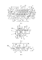
- фигура 1 - вид в перспективе электрифицированной направляющей;- figure 1 is a perspective view of an electrified guide;
- фигура 2 - фронтальный разрез увеличенной части профиля паза направляющей, подходящего для вмещения электрических проводов;- figure 2 is a frontal section of an enlarged part of the profile of the groove of the guide, suitable for accommodating electrical wires;
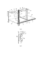
- фигура 3 - фронтальный вид варианта осуществления направляющей с ограниченными размерами;- figure 3 is a front view of an embodiment of a guide with limited dimensions;
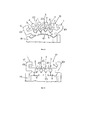
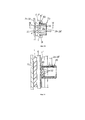
- фигуры 4 и 5 - электрифицированная направляющая в поперечном разрезе на последовательных этапах цикла производства;- figures 4 and 5 - electrified guide in cross section at successive stages of the production cycle;
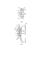
- фигура 6 - схематическое представление в перспективе использования электрифицированной направляющей в соответствии с данным изобретением для металлических полок, удерживающих товары;- figure 6 is a schematic perspective view of the use of an electrified guide in accordance with this invention for metal shelves holding goods;
- фигуры 7 и 8 - два различных способа установки электрифицированной направляющей или крепления устройств к ней;- figures 7 and 8 are two different ways of installing an electrified rail or attaching devices to it;
- фигура 9 - крепление электронной этикетки или другого периферийного устройства к электрифицированной направляющей;- figure 9 - mounting an electronic label or other peripheral device to an electrified guide;
- фигура 10 - крепление разъема с электрическими проводами;- figure 10 - mount connector with electrical wires;
- фигура 11 - другие детали группы разъемного соединения фигуры 10, в продольном разрезе в соответствии с линией XI-XI.- figure 11 - other details of the group of detachable connections of figure 10, in longitudinal section in accordance with line XI-XI.
Ссылаясь на фигуры 1 и 2, электрифицированная направляющая 1 в соответствии с данным изобретением производится путем экструзии композитного материала ПК или РРО, или другого термостойкого негорючего композитного материала, имеющего хорошие механические и электроизоляционные характеристики, имеет преимущественно U-образное или С-образное сечение (описывается далее). Направляющая имеет продольный канал 10 и основание 101 толщиной А приблизительно 4-4,5 мм, например примерно 4,2 мм, шириной В примерно 16 мм, плоскостную наружную нижнюю поверхность 2 с верхней стороной 102, являющейся внутренней по отношению к профилю; данная сторона также является плоскостной и фактически параллельна к указанной наружной стороне 2. Направляющая имеет, например симметрично расположенные, множество продольных пазов 3, например 4 паза, способных точно удерживать соответствующие металлические проводники 4, например в форме медных проводов или многожильных проводов (описывается далее). Хорошие результаты были получены при использовании медных проводов 4, имеющих сечение 1,5-1,8 мм, например, примерно 1,78 мм с тонким никелированным или позолоченным покрытием, которое делает их высоко устойчивыми к окислению, обеспечивая кроме того ограниченное электрическое сопротивление контакта с разъемами и контактами устройств (описывается далее), которые будут соединены со всеми или частью проводов 4. Как детально показано на фигуре 2, пазы 3 имеют общую глубину С примерно 2,18 мм, таким образом намного большую чем диаметр провода 4, который удерживается в нижней части самих пазов, открытых снаружи горловиной 103, имеющей глубину С примерно 0,4 мм и ширину D примерно 1,3 мм. Таким образом, две углубленные части, посредством которых пазы 3 удерживают провода 4, имеют каждая ширину Е примерно 0,25 мм. Таким образом, провода 4 находятся в поддерживаемой позиции по отношению к нижней поверхности 102 канала 10, и таким образом защищены от случайных контактов также благодаря ограниченной ширине горловины 103 пазов 3 (примерно 1,3 мм). Части 201 основания, отделяющие пазы 3 друг от друга, имеют фактически параллельные боковые стенки и зоны внешних углов 5, закругленные подходящим образом.Referring to figures 1 and 2, the electrified
В нижней части каждого паза 3 маленькие продольные промежуточные канавки 6 могут быть открытыми, широкими и глубокими примерно 0,5 мм и использоваться для ниже описываемого. Основание 101 направляющей имеет продольные боковые наружные канавки 7 и 8, по крайней мере по одной с каждой стороны. Эти боковые канавки предпочтительно имеют разные профили и размеры для улучшения установки направляющей 1, и/или для крепления к ней внешних компонентов, а также для облегчения необходимой ориентации самой направляющей в соответствии с различным целевым использованием внутренних электрических проводов 4. Часть указанных проводов может предназначаться для подачи электропитания, предпочтительно низковольтного, тогда как другие провода могут быть резервом или использоваться для передачи данных (описывается далее) или для других целей. В качестве неограничивающего примера, боковая канавка 7 имеет ширину F примерно 0,8 мм и фактически прямоугольный профиль, тогда как канавка 8 имеет большие размеры, чем канавка 7, и перпендикулярный V-образный профиль.At the bottom of each
На нижней стороне 2 основания 101 маленькие канавки или прорези 9 могут быть открыты, используемые для ниже описываемого, имеющие равные или разные размеры по сравнению с канавками 6, по отношению к которым данные канавки 9 имеют симметричное и смещенное положение.On the underside 2 of the
С постоянной ссылкой на фигуру 1, корпус направляющей 1 содержит как единое целое с концами основания 101 противолежащие крылышки 301, 401 с практически перевернутым L-образным профилем; удаленные части двух крылышек повернуты друг к другу для придания направляющей желаемой формы С, и таким образом для формирования в ней продольного канала 10 с общим перевернутым профилем Т, имеющего противолежащие и параллельные канавки 11, 11' на внутренних продольных сторонах нижней поверхности 102, предпочтительно имеющих равную высоту G примерно 1,85 мм, но имеющих разную глубину и профиль, для придания обязательной ориентации разъемов и периферийных устройств, которые могут быть прикреплены к направляющей 1, с обеспечением принудительного контакта контактов периферийных устройств с заранее определенными проводами 4 самой направляющей (описано далее). Для облегчения ориентации направляющей 1, также в соответствии с различным целевым назначением проводов 4, во внешней угловой области на одном из крылышек, например крылышке 401, расположена продольная выемка 12.With constant reference to figure 1, the housing of the
Толщина Н корпуса направляющей 1 примерно 7-8 мм, а толщина М различных областей, формирующих крылышки и основание самой направляющей поддерживается как можно более постоянной и составляет величину около 1,6 мм, так чтобы сделать равномерной усадку материала направляющей 1, избежать деформации и обеспечить производство с прямолинейной формой. Глубина Р канала 10 составляет примерно 3,45 мм, тогда как общая ширина N электрифицированной направляющей 1 составляет примерно 19-20 мм.The thickness H of the
В соответствии с вариантом осуществления на фигуре 3, электрифицированная направляющая может быть выполнена с экструдированным корпусом 100 без крылышек 301, 401, как в варианте осуществления на фигуре 1, так чтобы иметь толщину А примерно 4-4,5 мм и ширину N' значительно меньше 19 мм. В соответствии с вариантом осуществления на фигуре 3, направляющая может быть прикреплена основанием 2 на поверхности опоры, или с использованием, частично или полностью, боковых каналов 7, 8. Разъемы и электрические устройства могут быть прикреплены к корпусу 100 самой направляющей с использованием указанных боковых каналов 7, 8 и/или бокового профиля продольных кромок 501, 601 поверхности 102. Как видно, направляющая на фигуре 3 имеет сильно уменьшенные размеры, и ограниченное эстетическое воздействие, даже если ее сопротивление к скручиванию и изгибу определенно ниже, чем в предпочтительном варианте осуществления на фигуре 1, где крылышки 301, 401 с L-образным профилем действуют как продольные ребра жесткости.According to the embodiment of FIG. 3, the electrified guide can be made with an
Вышеуказанный пластиковый материал (ПК, РРО) используемый для корпуса направляющей 1 или 100, может быть экструдированным с конечными прозрачными или полупрозрачными свойствами, и таким образом использоваться для производства направляющей с дальнейшим ограниченным эстетическим воздействием и подходящей для применения с полками любого цвета. Серый цвет никелированного покрытия или золотистый цвет позолоченного покрытия электрических проводов 4 будет способствовать приятной эстетике соединения самой направляющей с полками любого цвета.The above plastic material (PC, PPO) used for the
Способ производства вышеописанной электрифицированной направляющей посредством экструзии включает следующие шаги:A method of manufacturing the above-described electrified guide by extrusion includes the following steps:
- подача в экструдер подходящего пластикового материала (например, ПК или РРО), и экструзия профиля;- feeding into the extruder a suitable plastic material (for example, PC or PPO), and profile extrusion;
- экструдированный профиль поступает в калибровочную станцию;- the extruded profile enters the calibration station;
- в калибровочной станции экструдированный профиль соединяется с медными проводами. Для избежания формирования нежеланельных напряжений в направляющей в калибровочном блоке и для придания достаточной пластичности проводам 4, перед их вставкой в калибровочной станции данные электрические провода 4 нагреваются до температуры приближенной к температуре экструдированного пластика, формирующего корпус направляющей; обычно данная температура составляет между 60 и 100°С.- in the calibration station, the extruded profile is connected to copper wires. To avoid the formation of unwanted stresses in the guide in the calibration block and to give sufficient ductility to the
- спаренный экструдированный профиль с проводами продольно вытягивается и охлаждается;- a twin extruded profile with wires is longitudinally stretched and cooled;
- спаренный экструдированный профиль с проводами разрезается на участки подходящей длины.- a twin extruded profile with wires is cut into sections of suitable length.
Во время этапа порезки используются приспособления прижима и противодавления для удержания электрических проводов 4 в своих соответствующих пазах. Это выполняется понятным и легко осуществимым путем для специалиста.During the cutting step, pressure and back pressure devices are used to hold the
Во время этапа калибровки экструдированный пластиковый профиль 101, 201, 301, 401 подвергается поперечному изгибу как показано на фигуре 4, так что канал 10 самой экструзии открывается наружу расходящимся профилем и пазы 3 открываются и расширяются так что в них могут быть быстро и касательно вставлены электрические провода 4 без существенного взаимодействия со стенкой 201 пазов 3, как показано на фигуре 4 стрелками Z. Подходящие непроиллюстрированные приспособления, легко понятные для специалиста, используются для заведения и поступательной вставки проводов 4 в пазы 3 экструдированного профиля, как схематически указано стрелками Z.During the calibration step, the extruded
На фигуре 4 видно, как продольные канавки 6 на нижней части пазов 3, и добавочные маленькие канавки 9 на внешней стороне основания 2 экструдированного профиля действуют в качестве петель сгибания, которые позволяют привести экструдированный профиль из состояния, показанного на фигуре 1, в состояние, показанное на фигуре 4 упругопластическим путем без опасного напряжения и в пазах, и в других частях сечения данного экструдированного профиля. На фигуре 4 видно, что те же канавки 6, несмотря на небольшое упругое деформирование, которое они претерпевают, благодаря своим ограниченным размерам по длине и ширине, действуют как ограничители хода и центрирующие ориентиры для обеспечения правильного расположения проводов 4 в нижней части пазов 3. Провода 4 никогда не смогут войти в канавки 6, как это могло бы произойти, если бы указанные канавки имели ширину, равную ширине горловины 103, которой пазы 3 открыты наружу. На этапе, следующем за этапом, показанным на фигуре 4, в заключительной части калибровочного блока, посредством подходящих роликов или других нижних, верхних, внешних и внутренних боковых ходовых приспособлений, как частично показано позицией 20 на фигуре 5, профиль 1 закрывается и приводится к первоначальным размерам как на фигуре 1, так что он достигает следующей охлаждающей станции уже с заданной формой, также благодаря упругой памяти экструдированного пластикового профиля, выходящего из экструдера.Figure 4 shows how the
Как показано на фигуре 5, канавки 6 позволяют быстрее охладить электрические провода 4. Также добавочные канавки 9 и 7, 8, 10, 11, 12 направляющей 1 содействуют быстрой и равномерной потере тепла, выработанного во время производства, обеспечивая правильный профиль и линейность самой направляющей.As shown in figure 5, the
На фигуре 6 позиция 21 показывает стойки стеллажа, которые поддерживают полки 22, удерживающие товары. Такой стеллаж может быть оснащен в его верхней части одной или большим количеством дополнительных полок 23 для поддержания приспособлений 24 способных подавать низкое напряжение к телеметрическим средствам 25, подходящих для предоставления и передачи данных. Электрифицированная направляющая в соответствии с данным изобретением может крепиться сбоку фактически по всей вертикальной длине стоек 21, как указано позицией 1', и более того может быть прикреплена по всей длине к передней горизонтальной стороне полок 22, как указанно позицией 1'' на той же фигуре 6, например, с помощью клеевой или двусторонней клеевой ленты 26, как на фигуре 7, примененной на задней стороне 2 самой направляющей, или с помощью средств зацепления 27, как на фигуре 8, которые сцепляются с боковыми канавками 7, 8 самой направляющей. Вертикальная направляющая 1' может быть соединена с приспособлениями 24 и 25 с помощью соответствующих электрических проводов 28, 28', оснащенных электрическими разъемами 29 вида, проиллюстрированного на фигурах 10 и 11, имеющая корпус с гибкими боковыми крылышками и профилем зацепа 30, 31 для разъемной фиксации и с обязательной ориентацией во внутренние каналы 11, 11' направляющей и оснащенная подпружиненными контактами 32 телескопического типа и осевого пружинения, имеющими диаметр примерно 1 мм, предпочтительно с никелированным или позолоченным покрытием и закругленной головкой.In figure 6, the
На фигуре 11 показано, что, в случае необходимости, разъем 29 может быть оснащен множеством контактов 32, пребываемых в контакте с одним и тем же проводом 4 направляющей, каждый раз необходимо формировать контактные области, имеющие широкую поверхность и более высокую электропроводность.Figure 11 shows that, if necessary, the
На фигуре 6 показано, что посредством одинаковых разъемов 29 и соответственной электропроводки 28'' вертикальная направляющая 1 может быть электрически соединена с горизонтальными направляющими 1'', на которых могут быть разъемно зафиксированы электронные этикетки 33, как к примеру на фигуре 9. Они также оснащены осевыми подпружиненными контактами 32, которые будут контактировать с необходимыми проводами 4 самой направляющей 1''. Электронные этикетки 33 также оснащены выступами 30, 31 для разъемной фиксации и обязательной ориентацией во внутренние каналы 11, 11' указанной направляющей 1''. Очевидно, что горизонтальные направляющие 1'' могут быть прикреплены с помощью двусторонней клеевой ленты 26 как в решении, показанном на фигуре 7, и что боковые каналы 7, 8 могут быть использованы для крепления любой вспомогательной детали к самой направляющей, как уже было упомянуто для варианта осуществления фигуры 1. Участки горизонтальной 1'' и вертикальной Г направляющих, которые не входят в контакт с разъемами 29 и электронными этикетками или другими вспомогательными деталями, могут быть съемно закрыты и защищены гибкими и электроизоляционными покрытиями, которые могут быть профилированы, как показано позицией 34 в варианте осуществления на фигуре 7. Как вариант, они могут быть получены путем поперечного разреза простой пластиковой полосы, как показано позицией 35 в варианте осуществления фигуры 8.Figure 6 shows that through the
Благодаря определенной конфигурации направляющей, в соответствии с которой все провода лежат на одной плоской видимой поверхности 102, в комбинации с подпружиненным контактом, предпочтительно имеющим закругленную головку, достигается то, что разъем может перемещаться продольно вдоль оси направляющей без потери электрического контакта и без повреждения канавок и проводов. Данный признак достигается в комбинации с использованием никелированных или позолоченных контактных поверхностей, которые предотвращают образование окислов и которые делают ненужным механическое проникновение металлов.Due to the specific configuration of the guide, according to which all the wires lie on one flat
Очевидно, что данное изобретение может включать многочисленные варианты осуществления без отступления от основных принципов описанного и проиллюстрированного изобретения, раскрытого в следующей формуле изобретения.Obviously, this invention may include numerous embodiments without departing from the basic principles of the described and illustrated invention disclosed in the following claims.
В пунктах формулы номера позиций, указанные в скобках, являются исключительно указательными и не ограничивают объем правовой охраны формулы изобретения.In the claims, the position numbers indicated in parentheses are solely indicative and do not limit the scope of legal protection of the claims.
Claims (8)
Applications Claiming Priority (2)
| Application Number | Priority Date | Filing Date | Title |
|---|---|---|---|
| ITBO2013A000415 | 2013-07-31 | ||
| IT000415A ITBO20130415A1 (en) | 2013-07-31 | 2013-07-31 | ELECTRIFIED RAIL, PARTICULARLY FOR THE ELECTRIFICATION OF METAL SHELVES, AND PROCEDURE FOR ITS PRODUCTION |
Publications (2)
| Publication Number | Publication Date |
|---|---|
| RU2014131109A RU2014131109A (en) | 2016-02-20 |
| RU2669309C2 true RU2669309C2 (en) | 2018-10-09 |
Family
ID=49085078
Family Applications (1)
| Application Number | Title | Priority Date | Filing Date |
|---|---|---|---|
| RU2014131109A RU2669309C2 (en) | 2013-07-31 | 2014-07-28 | Electrified rail, in particular, for powering metal shelving units and the way of its production |
Country Status (7)
| Country | Link |
|---|---|
| US (1) | US9379503B2 (en) |
| EP (1) | EP2833490B1 (en) |
| CN (1) | CN104348054B (en) |
| ES (1) | ES2749188T3 (en) |
| IT (1) | ITBO20130415A1 (en) |
| PL (1) | PL2833490T3 (en) |
| RU (1) | RU2669309C2 (en) |
Families Citing this family (14)
| Publication number | Priority date | Publication date | Assignee | Title |
|---|---|---|---|---|
| US8992238B2 (en) * | 2010-07-12 | 2015-03-31 | Ferno-Washington, Inc. | Mounting system having a mounting plate with mounting studs and electrical contacts |
| JP6557021B2 (en) * | 2015-02-17 | 2019-08-07 | スリーエム イノベイティブ プロパティズ カンパニー | Connector and connector assembly |
| ITUB20151917A1 (en) | 2015-07-07 | 2017-01-07 | Cefla S C | ELECTRIFIED RAIL WITH MAGNETS |
| CN108123337B (en) | 2016-11-28 | 2021-06-22 | 泰连公司 | Power connector assembly for communication system |
| PH12018050194A1 (en) * | 2017-05-18 | 2019-02-04 | Jf Microtechnology Sdn Bhd | Manufacturing process for kelvin contact assembly housing |
| US10673189B2 (en) | 2018-06-06 | 2020-06-02 | Te Connectivity Corporation | Power connector assembly for a communication system |
| US11837830B2 (en) * | 2018-08-27 | 2023-12-05 | Molex, Llc | Hinged busbar assembly |
| CN111224250B (en) * | 2018-11-23 | 2022-10-18 | 泰科电子(上海)有限公司 | Electric connector, electric connector assembly and electric equipment |
| US10939576B2 (en) | 2018-11-28 | 2021-03-02 | Te Connectivity Corporation | Power connector assembly for a communication system |
| IT201900000849A1 (en) * | 2019-02-08 | 2020-08-08 | Franco Oblatore | WIRELESS ELECTRIC CHANNEL FOR ELECTRICAL CONNECTIONS |
| DE102019126952A1 (en) * | 2019-10-08 | 2021-04-08 | Zumtobel Lighting Gmbh | Method of manufacturing a bus bar element for forming an elongated bus bar |
| JP2022126384A (en) * | 2021-02-18 | 2022-08-30 | オムロン株式会社 | Wire connection device |
| US20230202306A1 (en) * | 2021-12-28 | 2023-06-29 | Caterpillar Global Mining Equipment Llc | System and method for supporting elevated power rails |
| WO2024047570A1 (en) * | 2022-09-01 | 2024-03-07 | Bonfanti Gerolamo Angelo | Lighting device, coupling apparatus and lighting system |
Citations (7)
| Publication number | Priority date | Publication date | Assignee | Title |
|---|---|---|---|---|
| US4121879A (en) * | 1977-05-18 | 1978-10-24 | Bjorn Kokvik | Connector arrangement for conductor rails |
| US4812134A (en) * | 1988-05-23 | 1989-03-14 | Miller Ruth E | Wall mounted lighting track system |
| EP0343384A2 (en) * | 1988-05-23 | 1989-11-29 | DIL S.r.l. | Thermoplastic or similar extrusion for supporting simultaneously powered low and medium voltage electrical conductors and able to receive metal end reinforcement extrusions |
| EP0428055A2 (en) * | 1989-11-15 | 1991-05-22 | Neste Oy | Conductor rail |
| EP0828323A2 (en) * | 1996-08-30 | 1998-03-11 | Siemens Aktiengesellschaft | Bus bar system |
| FR2826791B1 (en) * | 2001-06-29 | 2005-11-04 | Universal Electric Corp | PERFECTED ELECTRIC BUS SYSTEM |
| US7122744B2 (en) * | 2002-02-23 | 2006-10-17 | Visplay International Ag | Profiled rail and accessories used as a suspension device |
Family Cites Families (21)
| Publication number | Priority date | Publication date | Assignee | Title |
|---|---|---|---|---|
| US2319375A (en) * | 1939-04-24 | 1943-05-18 | Gehr George H Von | Electrical outlet |
| US2234745A (en) * | 1939-09-26 | 1941-03-11 | Rarrel Alexander Von | Electric connecting device |
| BE757828A (en) * | 1969-11-21 | 1971-04-01 | Kabel Metallwerke Ghh | CONDUCTIVE RAIL TO FIX ON A WALL OR CEILING |
| IT8803520A0 (en) * | 1988-06-24 | 1988-06-24 | Beghelli G P B Srl | IMPROVEMENT IN CONNECTION AND QUICK CONNECTION SYSTEMS FOR LAMPS ESPECIALLY WITH WATERPROOF HOUSING |
| WO1994002050A1 (en) * | 1992-07-22 | 1994-02-03 | Crooymans Rene Wilhelm | Shelving support system |
| US5553412A (en) | 1993-03-25 | 1996-09-10 | Electronic Retailing Systems International, Inc. | Information display rail system |
| US5348485A (en) * | 1993-04-12 | 1994-09-20 | Electronic Retailing Systems Int'l Inc. | Electronic price display system with vertical rail |
| FI93595C (en) * | 1993-12-09 | 1995-04-25 | Hannu Sakari Taskinen | The conductor rail |
| US5890918A (en) * | 1994-12-01 | 1999-04-06 | Hierzer; Andreas | Low voltage current supply device |
| DE19526345C2 (en) * | 1995-07-19 | 1997-04-30 | Langmatz Lic Gmbh | Device for the electrical connection of preferably two electrical conductors |
| FI101754B1 (en) * | 1996-11-28 | 1998-08-14 | Nordic Aluminium Oyj | Arrangement in connection with the busbar pantograph |
| FR2765018B1 (en) | 1997-06-18 | 1999-10-01 | Rasec Communication Sa | ELECTRONIC DISPLAY LABEL SYSTEM |
| DE20101581U1 (en) | 2001-01-31 | 2002-06-20 | Keferstein, Ralf, 53757 Sankt Augustin | High-voltage conductor rail system |
| DE10216390A1 (en) * | 2002-04-12 | 2003-10-30 | Helmut Matysik | Electric current supply rail for two-phase or three-phase current for lamps, has U-shaped cross-section with conductor strips embedded in insulating support on either side of U-section |
| GB0328247D0 (en) * | 2003-12-06 | 2004-01-07 | Interplast Co Ltd | Improvements in and relating to electrical power, communication and data cable management systems |
| CN2814722Y (en) * | 2005-08-11 | 2006-09-06 | 南建丹 | Inserting distributing bus bar |
| US7425140B2 (en) * | 2005-12-30 | 2008-09-16 | Cooper Technologies Company | Lighting system and method |
| US9118990B2 (en) * | 2007-01-06 | 2015-08-25 | Apple Inc. | Connectors designed for ease of use |
| DE102007026906A1 (en) * | 2007-06-11 | 2008-12-24 | Wampfler Aktiengesellschaft | Insulating profile for a multi-pole conductor line |
| CN102882083A (en) * | 2011-07-14 | 2013-01-16 | 鸿富锦精密工业(深圳)有限公司 | Power supply device and cabinet power supply system with power supply device |
| DE102012007083B4 (en) * | 2012-04-11 | 2013-12-12 | Hoffmeister Leuchten Gmbh | conductor rail |
-
2013
- 2013-07-31 IT IT000415A patent/ITBO20130415A1/en unknown
-
2014
- 2014-07-28 RU RU2014131109A patent/RU2669309C2/en active
- 2014-07-28 CN CN201410363020.5A patent/CN104348054B/en not_active Expired - Fee Related
- 2014-07-29 US US14/445,812 patent/US9379503B2/en not_active Expired - Fee Related
- 2014-07-29 EP EP14178990.9A patent/EP2833490B1/en active Active
- 2014-07-29 ES ES14178990T patent/ES2749188T3/en active Active
- 2014-07-29 PL PL14178990T patent/PL2833490T3/en unknown
Patent Citations (7)
| Publication number | Priority date | Publication date | Assignee | Title |
|---|---|---|---|---|
| US4121879A (en) * | 1977-05-18 | 1978-10-24 | Bjorn Kokvik | Connector arrangement for conductor rails |
| US4812134A (en) * | 1988-05-23 | 1989-03-14 | Miller Ruth E | Wall mounted lighting track system |
| EP0343384A2 (en) * | 1988-05-23 | 1989-11-29 | DIL S.r.l. | Thermoplastic or similar extrusion for supporting simultaneously powered low and medium voltage electrical conductors and able to receive metal end reinforcement extrusions |
| EP0428055A2 (en) * | 1989-11-15 | 1991-05-22 | Neste Oy | Conductor rail |
| EP0828323A2 (en) * | 1996-08-30 | 1998-03-11 | Siemens Aktiengesellschaft | Bus bar system |
| FR2826791B1 (en) * | 2001-06-29 | 2005-11-04 | Universal Electric Corp | PERFECTED ELECTRIC BUS SYSTEM |
| US7122744B2 (en) * | 2002-02-23 | 2006-10-17 | Visplay International Ag | Profiled rail and accessories used as a suspension device |
Also Published As
| Publication number | Publication date |
|---|---|
| CN104348054B (en) | 2018-11-06 |
| EP2833490A1 (en) | 2015-02-04 |
| PL2833490T3 (en) | 2020-03-31 |
| US9379503B2 (en) | 2016-06-28 |
| ES2749188T3 (en) | 2020-03-19 |
| EP2833490B1 (en) | 2019-08-28 |
| US20150037991A1 (en) | 2015-02-05 |
| CN104348054A (en) | 2015-02-11 |
| ITBO20130415A1 (en) | 2015-02-01 |
| RU2014131109A (en) | 2016-02-20 |
Similar Documents
| Publication | Publication Date | Title |
|---|---|---|
| RU2669309C2 (en) | Electrified rail, in particular, for powering metal shelving units and the way of its production | |
| CN107202272B (en) | Goods shelf electricity taking head and goods shelf electricity taking system thereof | |
| CN102918722B (en) | The press-fit bus-bar improved and the busbar channel using this bus | |
| CN110492285B (en) | Goods shelf power supply system | |
| CN109888581B (en) | External track power supply system for plug-in type electricity taking | |
| CN201018142Y (en) | Cable connector assembly | |
| US9057513B2 (en) | Electrical assembly for connecting components of a lighting system for illuminating store shelving | |
| US9130327B2 (en) | Power assembly for display | |
| EP3443269B1 (en) | Domestic appliance with a cable tube between a door and a chassis of the appliance | |
| CN101626121A (en) | Cable connector assembly | |
| CN203387015U (en) | Electric power rail module | |
| EP2626953A1 (en) | Terminal fitting | |
| CN107143775A (en) | A kind of shelf power taking head and its shelf electricity getting system | |
| CN209325488U (en) | A kind of wiring board band can shear the flexible LED rope light of connection conductor | |
| CN110581395B (en) | Embedded electricity taking plug, electricity taking bracket and goods shelf electricity taking system | |
| CN104600441A (en) | Fast wiring terminal | |
| CN105375230B (en) | Insulate wheel trolley | |
| CN104281867B (en) | Electronic display label power supplying and fixing structure | |
| CN207398431U (en) | Charging gun pipette tips | |
| EP3321568B1 (en) | Laterally supported lights | |
| CN212462280U (en) | Get electric module, get electric installation and display system | |
| EP3675292B1 (en) | Power-supply connector for shelves and power-supply system with tracks for use thereof | |
| CN204333288U (en) | A kind of quick-connect terminal | |
| KR102056011B1 (en) | Smart window | |
| CN217642065U (en) | Soft bus bar with extrusion molding insulating layer of sliding structure |
Legal Events
| Date | Code | Title | Description |
|---|---|---|---|
| PC41 | Official registration of the transfer of exclusive right |
Effective date: 20220121 |