RU2667503C2 - Portable lamp, method of controlling light power of portable lamp, and communication device - Google Patents
Portable lamp, method of controlling light power of portable lamp, and communication device Download PDFInfo
- Publication number
- RU2667503C2 RU2667503C2 RU2013140864A RU2013140864A RU2667503C2 RU 2667503 C2 RU2667503 C2 RU 2667503C2 RU 2013140864 A RU2013140864 A RU 2013140864A RU 2013140864 A RU2013140864 A RU 2013140864A RU 2667503 C2 RU2667503 C2 RU 2667503C2
- Authority
- RU
- Russia
- Prior art keywords
- lamp
- infrared
- channel
- light
- signal
- Prior art date
Links
Images

Classifications
-
- H—ELECTRICITY
- H05—ELECTRIC TECHNIQUES NOT OTHERWISE PROVIDED FOR
- H05B—ELECTRIC HEATING; ELECTRIC LIGHT SOURCES NOT OTHERWISE PROVIDED FOR; CIRCUIT ARRANGEMENTS FOR ELECTRIC LIGHT SOURCES, IN GENERAL
- H05B47/00—Circuit arrangements for operating light sources in general, i.e. where the type of light source is not relevant
- H05B47/10—Controlling the light source
-
- B—PERFORMING OPERATIONS; TRANSPORTING
- B60—VEHICLES IN GENERAL
- B60Q—ARRANGEMENT OF SIGNALLING OR LIGHTING DEVICES, THE MOUNTING OR SUPPORTING THEREOF OR CIRCUITS THEREFOR, FOR VEHICLES IN GENERAL
- B60Q1/00—Arrangement of optical signalling or lighting devices, the mounting or supporting thereof or circuits therefor
- B60Q1/02—Arrangement of optical signalling or lighting devices, the mounting or supporting thereof or circuits therefor the devices being primarily intended to illuminate the way ahead or to illuminate other areas of way or environments
- B60Q1/04—Arrangement of optical signalling or lighting devices, the mounting or supporting thereof or circuits therefor the devices being primarily intended to illuminate the way ahead or to illuminate other areas of way or environments the devices being headlights
- B60Q1/14—Arrangement of optical signalling or lighting devices, the mounting or supporting thereof or circuits therefor the devices being primarily intended to illuminate the way ahead or to illuminate other areas of way or environments the devices being headlights having dimming means
- B60Q1/1415—Dimming circuits
- B60Q1/1423—Automatic dimming circuits, i.e. switching between high beam and low beam due to change of ambient light or light level in road traffic
-
- H—ELECTRICITY
- H05—ELECTRIC TECHNIQUES NOT OTHERWISE PROVIDED FOR
- H05B—ELECTRIC HEATING; ELECTRIC LIGHT SOURCES NOT OTHERWISE PROVIDED FOR; CIRCUIT ARRANGEMENTS FOR ELECTRIC LIGHT SOURCES, IN GENERAL
- H05B45/00—Circuit arrangements for operating light-emitting diodes [LED]
- H05B45/10—Controlling the intensity of the light
-
- H—ELECTRICITY
- H05—ELECTRIC TECHNIQUES NOT OTHERWISE PROVIDED FOR
- H05B—ELECTRIC HEATING; ELECTRIC LIGHT SOURCES NOT OTHERWISE PROVIDED FOR; CIRCUIT ARRANGEMENTS FOR ELECTRIC LIGHT SOURCES, IN GENERAL
- H05B47/00—Circuit arrangements for operating light sources in general, i.e. where the type of light source is not relevant
- H05B47/10—Controlling the light source
- H05B47/175—Controlling the light source by remote control
- H05B47/19—Controlling the light source by remote control via wireless transmission
- H05B47/195—Controlling the light source by remote control via wireless transmission the transmission using visible or infrared light
-
- H—ELECTRICITY
- H05—ELECTRIC TECHNIQUES NOT OTHERWISE PROVIDED FOR
- H05B—ELECTRIC HEATING; ELECTRIC LIGHT SOURCES NOT OTHERWISE PROVIDED FOR; CIRCUIT ARRANGEMENTS FOR ELECTRIC LIGHT SOURCES, IN GENERAL
- H05B47/00—Circuit arrangements for operating light sources in general, i.e. where the type of light source is not relevant
- H05B47/10—Controlling the light source
- H05B47/175—Controlling the light source by remote control
- H05B47/196—Controlling the light source by remote control characterised by user interface arrangements
- H05B47/1965—Controlling the light source by remote control characterised by user interface arrangements using handheld communication devices
Landscapes
- Engineering & Computer Science (AREA)
- Computer Networks & Wireless Communication (AREA)
- Mechanical Engineering (AREA)
- Lighting Device Outwards From Vehicle And Optical Signal (AREA)
- Circuit Arrangement For Electric Light Sources In General (AREA)
- Optical Communication System (AREA)
Abstract
Description
Область техникиTechnical field
Изобретение относится к портативным электрическим светильникам и, более конкретно, к портативному электрическому светильнику с антиослепляющей системой.The invention relates to portable electric lamps and, more particularly, to a portable electric lamp with an anti-dazzling system.
Уровень техникиState of the art
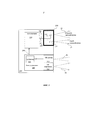
Заявитель настоящего изобретения выпустил в продажу портативный светильник с так называемым "реактивным" ("динамическим") управлением, описанный в международной заявке WO 2009/133309. Как показано на фиг.1, в этом случае используется головной светильник (фонарь), содержащий по меньшей мере один светодиод (СД) 11 и установленный вблизи него оптический датчик 14 для выработки сигнала, характеризующего свет, отраженный поверхностью объекта 16, освещаемого светильником. Этот сигнал обрабатывается управляющим контуром 13 в целях автоматического управления мощностью СД с учетом заданного порогового уровня. Тем самым обеспечивается автоматическая (без какого-либо ручного управления) регулировка светового пучка, испускаемого светильником, обеспечивающая адаптацию испускаемого света к окружению, при эффективном управлении потреблением энергии.The applicant of the present invention put on sale a portable lamp with the so-called "reactive" ("dynamic") control, described in international application WO 2009/133309. As shown in figure 1, in this case, a head lamp (lantern) is used, containing at least one LED (LED) 11 and an
Принцип подобного "динамического" освещения, несомненно, обеспечивает существенное улучшение головных фонарей и, в более широком контексте, портативных светильников, поскольку он позволяет непрерывно адаптировать светильник к потребностям в освещении.The principle of such “dynamic” lighting undoubtedly provides a significant improvement in the headlights and, in a wider context, portable luminaires, since it allows you to continuously adapt the luminaire to the lighting needs.
Однако данный светильник не устраняет проблемы ослепляющего воздействия на человека, обращенного лицом к источнику света.However, this lamp does not eliminate the problem of blinding effects on a person facing the light source.
Решение данной проблемы раскрыто в двух международных заявках РСТ/ЕР2012/000982 (WO 2012/119754) и РСТ/ЕР2012/000984 (WO 2012/119756), поданных заявителем настоящего изобретения 6.03.2012. Указанное решение требует использования датчика изображения, подключенного к процессору изображения, способному осуществлять обработку изображений с возможностью распознавания человеческого лица, более конкретно, глаза, чтобы автоматически уменьшать яркость, если человек в созданных условиях освещения подвергается ослепляющему воздействию света.A solution to this problem is disclosed in two international applications PCT / EP2012 / 000982 (WO 2012/119754) and PCT / EP2012 / 000984 (WO 2012/119756) filed by the applicant of the present invention on March 6, 2012. This solution requires the use of an image sensor connected to an image processor capable of processing images with the ability to recognize a human face, more specifically, the eyes, in order to automatically reduce the brightness if a person is exposed to blinding light under the created lighting conditions.
Данное решение требует использования сложной схемы на основе микропроцессора, обладающего возможностями цифровой обработки данных, и, к сожалению, применимо только в наиболее дорогих светильниках.This solution requires the use of a complex circuit based on a microprocessor with digital data processing capabilities, and, unfortunately, is applicable only to the most expensive fixtures.
Раскрытие изобретенияDisclosure of invention
Таким образом, представляется желательным разработать защитную систему, пригодную для любых портативных светильников (а не только для самых дорогих) и способную устранять или по меньшей мере существенно снижать риск слепящей засветки.Thus, it seems desirable to develop a protective system suitable for any portable luminaire (and not only for the most expensive) and capable of eliminating or at least significantly reducing the risk of glare.
Соответственно изобретение направлено на создание недорогого головного светильника, снабженного усовершенствованным управляющим механизмом с целью устранить или по меньшей мере существенно ослабить явление слепящего света, которое может представлять собой значительную опасность для человеческого глаза.Accordingly, the invention is directed to the creation of an inexpensive head lamp equipped with an improved control mechanism in order to eliminate or at least substantially reduce the phenomenon of blinding light, which can pose a significant danger to the human eye.
Другая задача, решаемая изобретением, состоит в разработке усовершенствованного способа управления интенсивностью света от головного светильника, позволяющего взаимодействовать с другими портативными или головными светильниками и предоставляющего пользователю новые возможности.Another problem solved by the invention is to develop an improved method of controlling the light intensity from the head lamp, allowing to interact with other portable or head lamps and providing the user with new opportunities.
Еще одна задача состоит в создании головного светильника, обладающего новыми функциональностями и содержащего средства связи, которые могут использоваться во многих применениях.Another objective is to create a head luminaire with new functionalities and containing communication tools that can be used in many applications.
Перечисленные задачи решены изобретением благодаря созданию портативного светильника, содержащего средства связи, в частности инфракрасный (ИК) канал (отличный от светового канала), позволяющий обмениваться идентификационными данными, конфигурационными параметрами или управляющими командами с другим портативным светильником.The above problems are solved by the invention due to the creation of a portable lamp containing communication means, in particular an infrared (IR) channel (different from the light channel), allowing the exchange of identification data, configuration parameters or control commands with another portable lamp.
Светильник предпочтительно содержит:The lamp preferably contains:
- по меньшей мере один источник света для генерирования (испускания) по меньшей мере одного светового пучка; иat least one light source for generating (emitting) at least one light beam; and
- средство для управления яркостью света в соответствии с управляющей информацией, генерируемой блоком управления.- means for controlling the brightness of the light in accordance with the control information generated by the control unit.
Блок управления содержит датчик для генерирования сигнала, характеризующего отраженный свет, и средство для обработки указанного сигнала с целью генерирования управляющей информации.The control unit comprises a sensor for generating a signal indicative of reflected light, and means for processing said signal to generate control information.
Источник света может представлять собой лампу (например галогенную) или, предпочтительно, излучатель типа СД, органических СД (ОСД) и др.The light source may be a lamp (for example, a halogen) or, preferably, an emitter of the type LED, organic LED (OSD), etc.
В конкретном варианте средства связи используются с целью избежать ситуации слепящего света.In a particular embodiment, communications are used to avoid a blinding light situation.
В одном конкретном варианте блок управления дополнительно содержит:In one specific embodiment, the control unit further comprises:
- инфракрасный (ИК) передатчик, способный периодически осуществлять передачу данных по каналу связи, использующему первый ИК пучок;- infrared (IR) transmitter capable of periodically transmitting data over a communication channel using the first infrared beam;
- приемное средство для восприятия ИК излучения в пределах приемного конуса с углом раскрытия меньшим, чем угол расхождения указанного первого пучка;- receiving means for receiving infrared radiation within the receiving cone with an opening angle smaller than the divergence angle of the specified first beam;
- средство обработки для обработки сигнала, характеризующего воспринимаемую ИК информацию, и для обнаружения присутствия второго светильника, генерирующего ИК сигнал; и- processing means for processing a signal characterizing the perceived IR information, and for detecting the presence of a second lamp generating an IR signal; and
- средство для существенного снижения мощности, генерируемой источниками света (в частности СД диодами) при обнаружении присутствия второго светильника, передающего данные по ИК-каналу.- a means to significantly reduce the power generated by light sources (in particular LED diodes) when detecting the presence of a second lamp transmitting data via infrared.
В предпочтительном варианте портативный светильник способен формировать широкий пучок и узкий пучок, интенсивность которого существенно ослабляется при обнаружении расположенного напротив него светильника, передающего данные по ИК-каналу. Альтернативно, портативный светильник способен формировать один или более несогласованных по направлению пучков с возможностью независимого управления ими.In a preferred embodiment, the portable lamp is capable of forming a wide beam and a narrow beam, the intensity of which is significantly weakened upon detection of a lamp located opposite it, transmitting data via infrared. Alternatively, a portable luminaire is capable of forming one or more beams inconsistent in direction with the possibility of independent control.
В конкретном варианте при приближении конца срока службы батареи блок управления продолжает испускать ИК-излучение при прекращении формирования световых пучков с тем, чтобы продлить защиту пользователя светильником от ситуаций слепящего света.In a specific embodiment, as the battery reaches the end of its life, the control unit continues to emit infrared radiation when the formation of light beams ceases in order to extend the protection of the user of the lamp from glare situations.
Светильник предпочтительно содержит также конфигурирующее средство, обеспечивающее заданную конфигурацию, в частности в соответствии с одним или более из заданных профилей, с использованием порта USB, обеспечивающего возможность коммуникации с компьютером, тачпадом или смартфоном.The luminaire preferably also contains configuration means providing a predetermined configuration, in particular in accordance with one or more of the predetermined profiles, using a USB port enabling communication with a computer, touchpad or smartphone.
Изобретение предназначено, в частности, для использования в головном светильнике.The invention is intended, in particular, for use in a head lamp.
В другом варианте изобретение обеспечивает создание устройства связи, предназначенного для помещения на голову пользователя или на портативный светильник, используемый пользователем. Устройство по изобретению содержит средство связи для коммуникации с портативным светильником с целью защищать пользователя в ситуациях с потенциально опасной слепящей засветкой.In another embodiment, the invention provides a communication device designed to be placed on the user's head or on a portable lamp used by the user. The device according to the invention comprises communication means for communication with a portable lamp in order to protect the user in situations with potentially dangerous glare.
Изобретение предлагает также способ управления мощностью, генерируемой портативным светильником, содержащим источник света с одним или более излучателями (галогенной лампой, СД, ОСД и т.д.), испускающими по меньшей мере один световой пучок, причем портативный светильник содержит средства для формирования приемопередающего ИК-канала с конусом приема, имеющим меньший угол раскрытия, чем угол расхождения передающего пучка.The invention also provides a method for controlling the power generated by a portable lamp containing a light source with one or more emitters (halogen lamp, LED, OSD, etc.) emitting at least one light beam, the portable lamp containing means for forming a transceiver IR -channel with a receiving cone having a smaller opening angle than the divergence angle of the transmitting beam.
Способ по изобретению характеризуется тем, что включает следующие шаги:The method according to the invention is characterized in that it includes the following steps:
- выдачу фрейма данных по указанному ИК-каналу;- issuing a data frame on the specified infrared channel;
- прием ИК-сигнала, детектируемого в пределах указанного приемного конуса;- receiving an infrared signal detected within the specified receiving cone;
- детектирование ИК-сигнала, испускаемого другим светильником в указанном ИК-канале; и- detecting an infrared signal emitted by another lamp in said infrared channel; and
- уменьшение световой мощности светильника в качестве отклика на обнаружение другого светильника, испускающего в ИК-канале.- reducing the luminous power of the lamp in response to the detection of another lamp emitting in the infrared channel.
Краткое описание чертежейBrief Description of the Drawings
Другие особенности, решаемые задачи и преимущества изобретения станут ясны из нижеследующего описания неограничивающих примеров осуществления изобретения и из прилагаемых чертежей.Other features, objectives and advantages of the invention will become apparent from the following description of non-limiting embodiments of the invention and from the accompanying drawings.
На фиг.1 представлена общая схема известного светильника, обеспечивающего динамическое освещение.Figure 1 presents a General diagram of a known lamp that provides dynamic lighting.
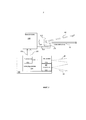
На фиг.2 представлена общая схема первого варианта светильника, использующего два пучка, узкий и широкий.Figure 2 presents a General diagram of the first embodiment of the lamp using two beams, narrow and wide.
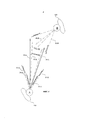
Фиг.3 иллюстрирует второй вариант светильника, использующего два взаимно не согласованных по направлению пучка.Figure 3 illustrates a second embodiment of a luminaire using two mutually inconsistent beam directions.
На фиг.4 схематично показан головной светильник по фиг.2, чтобы проиллюстрировать процесс управления.FIG. 4 schematically shows the head lamp of FIG. 2 to illustrate the control process.
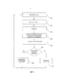
На фиг.5 иллюстрируется вариант процесса коммуникации, осуществляемого головным светильником согласно варианту изобретения.5 illustrates an embodiment of a communication process carried out by a head lamp according to an embodiment of the invention.
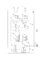
На фиг.6 представлен третий вариант светильника, использующий микропроцессорную архитектуру.Figure 6 presents the third version of the lamp using microprocessor architecture.
Осуществление изобретенияThe implementation of the invention
Далее будет рассмотрена возможность существенного усовершенствования работы портативного светильника, такого как головной светильник, факел или любое иное мобильное устройство, снабженное автономной осветительной системой, например включающей “реактивную” (“динамическую”) систему регулировки. Светильник по изобретению содержит:Next, we will consider the possibility of significant improvement in the operation of a portable lamp, such as a head lamp, a torch, or any other mobile device equipped with an autonomous lighting system, for example, including a “reactive” (“dynamic”) adjustment system. The lamp according to the invention contains:
- любой источник света, например содержащий один или более СД или галогенную лампу, ОСД и др., и- any light source, for example containing one or more LEDs or a halogen lamp, OSD, etc., and
- средство для управления яркостью СД в качестве отклика на управляющую информацию, сгенерированную блоком управления.- means for controlling the brightness of the LED as a response to the control information generated by the control unit.
Блок управления содержит датчик, генерирующий сигнал, характеризующий отраженный свет, и средство обработки для обработки данного сигнала, чтобы сгенерировать управляющую информацию. Обычно в качестве единственного датчика можно использовать фотодатчик. В общем случае единственным датчиком может служить любой датчик, способный генерировать базовую аналоговую или цифровую информацию, за исключением датчика изображения, который генерирует изображение, структурированное в виде матрицы пикселей, и который был рассмотрен в вышеупомянутой патентной заявке. Несомненным преимуществом фотодатчика перед датчиком изображения является низкая производственная стоимость, важная для потребительского рынка.The control unit comprises a sensor generating a signal characterizing reflected light, and processing means for processing the given signal to generate control information. Typically, a photo sensor can be used as the only sensor. In the general case, the only sensor that can be used is any sensor capable of generating basic analog or digital information, with the exception of the image sensor, which generates an image structured as a pixel matrix, and which has been discussed in the aforementioned patent application. The undoubted advantage of the photosensor over the image sensor is the low production cost, which is important for the consumer market.
Светильник содержит также средства связи, в частности на основе ИК канала, выполненного отдельно от светового канала и служащего для обмена идентификационными данными, параметрами конфигурации и/или управляющими командами с другим портативным светильником. Альтернативно, возможно использование канала связи, реализуемого посредством модуляции света или даже других средств беспроводной коммуникации.The lamp also contains communication means, in particular based on an IR channel, made separately from the light channel and used to exchange identification data, configuration parameters and / or control commands with another portable lamp. Alternatively, it is possible to use a communication channel implemented by modulating light or even other means of wireless communication.
В конкретном варианте светильника средства связи используются, чтобы избежать ситуации слепящего света.In a particular embodiment of the luminaire, communication means are used to avoid a blinding light situation.
Должно быть понятно, что рассмотренные варианты приводятся только как примеры и что специалист сможет адаптировать изобретение к другим осветительным устройствам с целью повышения их операционной безопасности.It should be clear that the options discussed are provided only as examples and that a specialist will be able to adapt the invention to other lighting devices in order to increase their operational safety.
Первый вариант, использующий два пучка, широкий и узкийThe first option, using two beams, wide and narrow
На фиг.2 представлена общая схема первого варианта светильника 200 (принимается, что он является головным светильником), в котором имеется реактивная (динамическая) регулировка интенсивности света, испускаемого в виде двух пучков 10 и 20, соответственно узкого и широкого. Светильник 200 содержит блок 210 питания, подключенный к блоку 220 управления, и излучатель (источник света) 230, содержащий множество светодиодов (СД), каждый из которых снабжен отдельной фокусирующей системой.Figure 2 presents a General diagram of the first embodiment of the lamp 200 (it is assumed that it is the head lamp), in which there is a reactive (dynamic) adjustment of the intensity of the light emitted in the form of two
На фиг.2, только для наглядности, показан комплект из двух СД 231 и 232, подключенных к выводам 233 и 234 блока 210 питания соответственно. В общем случае, чтобы увеличить световой поток светильника, можно использовать большее количество диодов в сочетании с единственной фокусирующей оптической системой и даже использовать большее количество оптических систем с целью расширить область применения светильника.Figure 2, only for clarity, shows a set of two
В конкретном рассматриваемом варианте СД 231 и 232 получают питание соответственно через выводы 233 и 234 от контуров, управляемых посредством управляющей информации или управляющего сигнала 299, генерируемого блоком 220 управления.In the particular embodiment under consideration,
Блок 210 питания содержит все компоненты, которые обычно присутствуют в светильниках на базе СД (светодиодных светильниках), используемых для получения светового пучка высокой интенсивности, как правило, с применением широтно-импульсной модуляции (ШИМ), которая хорошо известна специалистам как аналогичная применяемой в аудиосистемах класса D. Управление ШИМ осуществляется посредством управляющего сигнала 299. В этой связи следует отметить, что термин "сигнал" в контексте изобретения относится к электрическому параметру - току или напряжению, - используемому для управления блоком питания и, в частности, для управления ШИМ, применяемой в цепях питания СД 231, 232. Однако данный пример не является ограничивающим, и "управляющий сигнал 299" может быть заменен "управляющей информацией", т.е. логической информацией, которая может храниться в регистре или в памяти и переноситься в блок 210 питания, чтобы получить требуемый световой поток. В одном конкретном варианте представляется возможным интегрировать блок управления и блок питания в единый модуль или в единую интегральную схему.The
Поэтому специалисту будет очевидно, что понятие "управляющего сигнала 299" охватывает как варианты, основанные на управляющей электрической переменной - токе или напряжении, - так и варианты, в которых управление осуществляется посредством логической информации, доставляемой в блок питания. В связи с этим далее понятия управляющего сигнала и управляющей информации рассматриваются как эквивалентные.Therefore, it will be obvious to a person skilled in the art that the concept of "
Компоненты, составляющие блок 210 питания (ключи и контура), хорошо известны специалистам, так что для облегчения понимания изобретения их описание будет сокращено. Аналогично, сведения о различных аспектах ШИМ можно найти в опубликованной литературе.The components making up the power supply unit 210 (keys and circuits) are well known to those skilled in the art, so that a description thereof will be shortened to facilitate understanding of the invention. Similarly, information on various aspects of PWM can be found in the published literature.
Конкретный пример блока питания будет более подробно описан далее со ссылками на фиг.6.A specific example of a power supply will be described in more detail below with reference to Fig.6.
Как показано на фиг.2, блок 220 управления содержит фотодатчик 222, оптическая ось которого параллельна оптическим осям СД 231 и 232. Фотодатчик 222 генерирует сигнал, характеризующий воспринимаемое им излучение, в том числе излучение, отраженное окружающими объектами (окружающей средой). Сигнал фотодатчика поступает в процессор 221, который производит его обработку.As shown in FIG. 2, the
Блок управления дополнительно содержит инфракрасный (ИК) излучатель 223, имеющий коллимирующую систему с относительно большим углом расхождения - как это проиллюстрировано на фиг.2 посредством пучка 30 - и способную периодически осуществлять передачу потока данных по ИК-линии связи.The control unit further comprises an infrared (IR) emitter 223 having a collimating system with a relatively large angle of divergence — as illustrated in FIG. 2 by means of a
Блок управления содержит также ИК-приемник для приема ИК-сигнала при осуществлении, по ИК-линии связи, коммуникации, которая может быть установлена с другим головным светильником, способным к взаимодействию со светильником 200 (и в этом смысле аналогичного ему) и расположенным напротив светильника 200.The control unit also contains an infrared receiver for receiving an infrared signal when communicating via an infrared communication line, which can be installed with another head lamp capable of interacting with a lamp 200 (and in this sense similar to it) and located opposite the
В варианте, представленном на фиг.2, один и тот же датчик 222 используется для восприятия излучения в видимом диапазоне (света), отраженного от окружающих объектов, и для приема инфракрасного пучка от потенциально присутствующего аналогичного светильника.In the embodiment of FIG. 2, the
Альтернативно, можно иметь два отдельных датчика: один датчик для света (отраженного от окружающих объектов), а другой датчик специально для приема инфракрасного излучения от аналогичного светильника. Этот вариант имеет то преимущество, что позволяет использовать коллимирующие системы, специально адаптированные для инфракрасного пучка и для светового пучка. Должно быть понятно, что конкретная коллимирующая система, используемая для инфракрасного излучения (проиллюстрированного узким пучком 40), должна соответствовать более узкому пучку, чем пучок 30, ассоциированный с инфракрасным излучателем.Alternatively, you can have two separate sensors: one sensor for light (reflected from surrounding objects), and the other sensor specifically for receiving infrared radiation from a similar lamp. This option has the advantage that it allows the use of collimating systems specially adapted for the infrared beam and for the light beam. It should be understood that the particular collimating system used for infrared radiation (illustrated by narrow beam 40) should correspond to a narrower beam than
Поэтому, если желательно принимать широкий пучок видимого света, то может оказаться целесообразным (в отличие от варианта по фиг.2) использовать два отдельных датчика (для светового и ИК-пучков), чтобы обеспечить прием ИК-излучения в пределах конуса с малым углом раскрытия.Therefore, if it is desirable to receive a wide beam of visible light, it may be appropriate (in contrast to the variant of FIG. 2) to use two separate sensors (for light and IR beams) to ensure that infrared radiation is received within a cone with a small opening angle .
Согласно варианту по фиг.2 сигнал, принятый фотодатчиком 222, или по меньшей мере сигнал, соответствующий (в варианте по фиг.2) световой составляющей, подвергается адекватной обработке процессором 221 в блоке 220 управления (после преобразования сигнала в цифровую форму надлежащим аналого-цифровым преобразователем (на фиг.2 не изображен)).According to the embodiment of FIG. 2, the signal received by the
В рамках этой обработки может оказаться необходимым выполнение процессором, последовательно или параллельно, различных операций над цифровым представлением сигнала, сгенерированного датчиком 222, в частности адекватных операций фильтрации, статистических расчетов, демодуляции, кодирования/декодирования с целью повышения надежности в отношении шума и других факторов при декодировании фрейма данных, полученных от способного к взаимодействию светильника, или при установлении связи со способным к взаимодействию устройством, инициирующим коммуникацию со светильником. Такие операции хорошо известны в области обработки сигналов, особенно в части выделения одной конкретной компоненты сигнала, которая, как ожидается, несет цифровую информацию. Как следствие, в их описании нет необходимости.As part of this processing, it may be necessary for the processor, sequentially or in parallel, to perform various operations on the digital representation of the signal generated by the
Осуществив цифровую информацию сигнала, а также декодировав информацию, принятую от аналогичного светильника, процессор 221 способен сгенерировать управляющую информацию 299, подаваемую в блок питания и обеспечивающую возможность раздельного управления узким и широким световыми пучками, испускаемыми СД 231 и 232 соответственно.By performing digital signal information, as well as decoding information received from a similar lamp, the
В общем случае можно рассмотреть несколько стратегий, приемлемых для блока 210 питания.In the general case, several strategies suitable for
В первом варианте инфракрасная коммуникация предназначена для передачи фрейма данных, должным образом сформатированного и промодулированного, посредством ИК-сигнала, передаваемого ИК-излучателем и уникальным образом идентифицирующего портативный светильник.In the first embodiment, infrared communication is intended to transmit a data frame, properly formatted and modulated, by means of an infrared signal transmitted by an infrared emitter and uniquely identifying a portable lamp.
Альтернативно, фрейм данных, поступающий в ИК-канал, содержит, в дополнение к идентификатору светильника, конфигурационные параметры, которыми должны обменяться два способных к взаимодействию светильника, и даже управляющие команды для операций, которые должны быть выполнены в светильнике.Alternatively, the data frame entering the infrared channel contains, in addition to the luminaire identifier, configuration parameters that two interoperable luminaires must exchange, and even control commands for operations that must be performed on the luminaire.
При таком выполнении два расположенные друг против друга светильника могут обмениваться данными, принимать команды и, в общем случае, обновлять свои конфигурационные параметры, а также, основываясь на переданных данных, осуществлять внутренние операции.With this arrangement, two luminaires located opposite each other can exchange data, receive commands and, in general, update their configuration parameters, and also, based on the transmitted data, perform internal operations.
Благодаря этому становятся доступными многие новые возможности и функциональности.Thanks to this, many new features and functionalities become available.
Далее, со ссылкой на фиг.4, будет рассмотрен конкретный пример новой возможности, а именно обеспечения антиослепляющего свойства, весьма полезного для переносных светильников. Эта новая функциональность, обеспеченная наличием антиослепляющей системы и проиллюстрированная на фиг.4, особенно полезна для пользователя портативным светильником.Next, with reference to figure 4, we will consider a specific example of a new feature, namely the provision of anti-glare properties, very useful for portable lamps. This new functionality, provided by the presence of an anti-glare system and illustrated in FIG. 4, is particularly useful for a user with a portable lamp.
На фиг.4 на виде сверху, весьма схематично показаны два пользователя, А и В (обозначенные как 410 и 420 соответственно), находящиеся друг против друга. Голова каждого пользователя представлена кружком, несущим головной светильник.Figure 4 in a top view, very schematically shows two users, A and B (indicated as 410 and 420, respectively), who are opposite each other. Each user's head is represented by a circle carrying a head lamp.
Для облегчения понимания цифровые обозначения, использованные на фиг.2 применительно к различным пучкам, световым и инфракрасным, широким и узким, использованы и на фиг.4.To facilitate understanding, the digital designations used in FIG. 2 with respect to various beams, light and infrared, wide and narrow, are also used in FIG. 4.
Можно видеть, что пользователь А, который, видимо, смотрит в сторону пользователя В, имеет головной светильник, формирующий два световых пучка 10-А и 20-А (узкий и широкий соответственно) и широкий инфракрасный пучок 30-А. При этом данный светильник, возможно, принимает в своем конусе 40-А приема узкий ИК-пучок.You can see that user A, who is apparently looking towards user B, has a head lamp that forms two light beams 10-A and 20-A (narrow and wide, respectively) and a wide infrared beam 30-A. Moreover, this lamp may receive a narrow infrared beam in its receiving cone 40-A.
Симметрично, пользователь В также имеет головной светильник согласно изобретению, формирующий два световых пучка (не изображенных на фиг.4 для большей наглядности) и широкий ИК-пучок 30-В и, возможно, принимающий узкий ИК-пучок, распространяющийся в пределах конуса 40-В.Symmetrically, user B also has a head lamp according to the invention, forming two light beams (not shown in FIG. 4 for greater clarity) and a wide IR beam 30-B and possibly receiving a narrow IR beam propagating within the cone 40- AT.
Светильник сконструирован таким образом, что конус приема для инфракрасного пучка, воспринимаемого датчиком 222, имеет меньший угол раскрытия, чем угол расходимости пучка, испускаемый ИК-излучателем 223.The luminaire is designed in such a way that the receiving cone for the infrared beam sensed by the
Согласно одному варианту блок 220 управления в светильнике субъекта А управляет существенным снижением интенсивности света, излучаемого светильником, когда ИК-датчик 222 детектирует, в своем узком конусе 40-А приема, поток ИК-излучения, который, будучи должным образом демодулирован, декодирован и т.д., указывает на присутствие аналогичного головного светильника.According to one embodiment, the
В одном конкретном варианте блок 220 управления только обеспечивает отключение или по меньшей мере существенное ослабление интенсивности узкого пучка, который может подвергнуть субъект В воздействию неприятного или опасного слепящего света.In one particular embodiment, the
На фиг.5 более подробно иллюстрируется способ, соответствующий варианту по фиг.2, в котором единственный датчик 222 осуществляет восприятие как инфракрасных, так и световых пучков.Figure 5 illustrates in more detail the method corresponding to the variant of figure 2, in which a
На шаге 510 способ начинает осуществляться с периодического восприятия сигнала, генерируемого датчиком 222.At
На шаге 520 производится аналого-цифровое преобразование (АЦП) и преобразованный сигнал записывается в память (шаг 530).At
Затем, на шаге 540, процессор 221 осуществляет обработку информации, записанной в памяти, в частности относящейся к видимой (световой) компоненте, воспринятой, после отражения, датчиком 222. Такая обработка может включать различные операции, в частности фильтрацию или статистические расчеты (усреднение и др.).Then, at
После этого, также на шаге 540, процессор 221 рассчитывает, на основе результатов обработки данных по видимой компоненте, управляющую информацию 299 для ее передачи в блок 210 питания. В частности, задается уровень световой мощности как для узкого, так и для широкого пучков.After that, also at
Затем, на шаге 550, процессор осуществляет более специфичную обработку инфракрасной компоненты сигнала, воспринятой датчиком 222 (или отдельным ИК-датчиком, если он имеется), с целью фильтрования, демодулирования и декодирования информации, если она была получена по ИК-каналу связи.Then, at
Именно по завершении шага 560 процессор 221 потенциально может опознать способный к взаимодействию головной светильник.It is at the end of
На шаге 560 процессор 221 выполняет тест, чтобы определить, был ли, действительно, обнаружен способный к взаимодействию головной светильник. Если да, способ продолжается шагом 570, на котором производится существенное ослабление интенсивности света, испускаемого по меньшей мере в виде одного из пучков 10 и 20, прежде всего узкого пучка 10.At
Если способный к взаимодействию светильник не был обнаружен, способ продолжается шагом 580, на котором используется результат шага 540, а именно управляющая информация 299, рассчитанная при обработке данных по световому пучку. Эта информация подается в блок 210 питания, обеспечивая "динамическое" (“реактивное”) регулирование.If an interoperable luminaire has not been detected, the method continues with
Затем способ возвращается на шаг 510, чтобы осуществить обработку нового отсчета сигнала, воспринятого датчиком 222.The method then returns to step 510 to process a new sample of the signal received by the
Можно видеть, что при осуществлении способа по фиг.5 процессор 221 может производить известную "динамическую" (“реактивную”) регулировку, а также существенно ослаблять испускаемые световые пучки, когда в поле зрения, соответствующее узкому пучку инфракрасного канала, входит аналогичный светильник.It can be seen that in the implementation of the method of FIG. 5,
В результате реализуется значительно более эффективный способ управления интенсивностью света, поскольку он одновременно учитывает как "световую" информацию, воспринимаемую датчиком 222 и соответствующую отклику на отражение от окружающих объектов, так и информацию, поступающую по инфракрасному каналу связи, чтобы реализовать нужную конфигурацию или выполнить выработанные команды и, тем самым, избежать воздействия слепящим светом на пользователя аналогичным светильником.As a result, a much more effective way of controlling the light intensity is implemented, since it simultaneously takes into account both the “light” information perceived by the
Действительно, когда процессор 221 детектирует, внутри узкого конуса приема ИК-датчика, присутствие аналогичного головного светильника, тот же самый процессор управляет существенным ослаблением по меньшей мере одного из световых пучков.Indeed, when the
Благодаря такому, весьма полезному детектированию именно головной светильник пользователя А, который "обнаруживает" в пределах узкого конуса приема ИК-излучения присутствие аналогичного светильника (принадлежащего пользователю В), испускающего широкий пучок света, уменьшает свою яркость, даже если управляющая система светильника В не обнаружила свет от светильника А.Thanks to this very useful detection, it is precisely the head lamp of user A that "detects" within the narrow cone of receiving infrared radiation the presence of a similar lamp (belonging to user B) that emits a wide beam of light, decreases its brightness even if the control system of lamp B does not detect light from lamp A.
Действительно, пользователь В в большей степени подвержен опасности слепящего света, поскольку именно в его сторону смотрит пользователь А и именно на него падает, в частности, узкий видимый пучок светильника А. Поэтому пользователю В достаточно повернуть свою голову в сторону пользователя А, чтобы подвергнуться опасной засветке. Обратное несправедливо: поворот головы пользователя А не приведет к его ослепляющей засветке, т.к. пользователь В не смотрит на него.Indeed, user B is more prone to the danger of blinding light, because user A is looking in his direction and it is precisely him who falls, in particular, the narrow visible beam of lamp A. Therefore, user B needs only to turn his head towards user A in order to be exposed to danger flare. The reverse is unfair: turning the head of user A will not lead to its blinding exposure, because user B does not look at him.
Таким образом, асимметричный процесс ослабления яркости света при детектировании сигнала, переданного способным к взаимодействию светильником, позволяет существенно снизить риск слепящего света при сохранении уровня освещения, достаточного для каждого пользователя.Thus, the asymmetric process of dimming the brightness of the light during the detection of a signal transmitted by an interoperable lamp can significantly reduce the risk of blinding light while maintaining a sufficient lighting level for each user.
Следует отметить, что ослабление интенсивности света, осуществляемое на шаге 570, является только одним неограничивающим примером.It should be noted that the attenuation of light intensity carried out at
В конкретном варианте блок управления головного светильника содержит систему контроля для сохранения питания системы испускания ИК-излучения при прекращении питания одного или более световых пучков, когда напряжение питания падает ниже заданного порогового уровня. В результате пользователь светильником может быть уверен, что система его защиты от воздействия слепящей засветки функционирует даже при почти полностью разряженной батарее.In a particular embodiment, the head lamp control unit comprises a monitoring system for maintaining power to the infrared emission system when one or more light beams are cut off when the supply voltage drops below a predetermined threshold level. As a result, the user of the luminaire can be sure that its system of protection against the effects of blinding illumination functions even with an almost completely discharged battery.
В другом конкретном варианте ИК-передатчик может быть скомбинирован с любым светильником общего назначения, чтобы и в этом случае обеспечить защиту пользователя таким светильником от слепящего света, идущего от других источников света. С этой целью достаточно удалить из светильника согласно описанным примерам все компоненты, связанные с генерированием световых пучков, и сохранить только "управляющую" часть в сочетании с ИК-излучателем 223 и ИК-датчиком 222.In another specific embodiment, the IR transmitter can be combined with any general-purpose lamp, in which case to protect the user from such a lamp from blinding light coming from other light sources. For this purpose, it is enough to remove from the lamp according to the described examples all the components associated with the generation of light beams, and save only the "control" part in combination with an
Второй вариант светильника с двумя непараллельными пучкамиThe second version of the lamp with two non-parallel beams
На фиг.3 иллюстрируется вариант (альтернативный по отношению к варианту по фиг.2), в котором излучатель 230 первого варианта заменен двумя комплектами СД, имеющими слегка различающиеся оптические оси. Как видно из фиг.3, первый комплект 331 диодов (показан только один СД этого комплекта) генерирует первый пучок, имеющий ось 50, тогда как второй комплект 332 диодов (показан только один СД этого комплекта) генерирует второй пучок, имеющий ось 60. Два комплекта диодов 331, 332 питаются, соответственно через выводы 333 и 334, от одного блока 310 питания, аналогичного блоку 210 по фиг.2 и также находящегося под контролем блока 320 управления.Figure 3 illustrates a variant (alternative to the variant of figure 2), in which the
Хотя фиг.3 иллюстрирует вариант только с двумя комплектами диодов и, следовательно, с двумя осями 50 и 60 пучков, специалист легко сможет адаптировать изобретение для получения большего количества световых пучков с различными профилями.Although figure 3 illustrates an option with only two sets of diodes and, therefore, with two
В варианте по фиг.3 блок 320 управления генерирует два варианта управляющей информации или управляющих сигналов 390 и 391, предназначенных для управления интенсивностью излучения СД 331 и 332 соответственно.In the embodiment of FIG. 3, the
Как и в двух первых вариантах, возможность генерирования управляющей информации или управляющих сигналов 390 и 391 обеспечивается цифровой обработкой сигнала, генерируемого фотодатчиком 322, воспринимающим два световых пучка и ИК-пучки.As in the first two options, the ability to generate control information or
Далее, со ссылкой на фиг.6, будет описан еще один конкретный вариант, в котором блок 210 питания содержит батарею (не изображена), вырабатывающую напряжение Vcc питания, и два силовых ключа 121 и 122, через которые ток питания подается соответственно через выводы 234 и 233 на два СД 232 и 231. Сигналы управления ключами 121, 122 промодулированы посредством блоков 131, 132 ШИМ (PWM). Ключи 121 и 122 могут быть полупроводниковыми ключами, например в виде биполярных транзисторов, полевых транзисторов или полевых МОП-транзисторов.Next, with reference to FIG. 6, another specific embodiment will be described in which the
Обе цепи 233 и 234 управляются посредством управляющей информации или управляющих сигналов 113 и 114, генерируемых управляющим блоком 500, интегрированным в блок 220 управления.Both
Управляющий блок 500 содержит процессор 221, связанный посредством обычных адресной шины, шины данных и управляющей шины с памятью 225 с произвольным доступом (RAM) или с постоянной памятью 226 (ROM), например с электрически стираемой программируемой постоянной памятью и т.д.The
На фиг.6 датчик 222 представлен, в качестве примера, как аналоговый датчик, работающий как в видимом, так и в ИК-диапазоне и подключенный к аналого-цифровому (A/D) преобразователю для преобразования аналоговых сигналов в цифровую информацию, которая может быть доступна процессору 221 через шину данных, адресную шину и т.д.6, the
В конкретном варианте можно рассмотреть возможность реализации функций приема ИК-излучения и обработки сигнала посредством единственной интегральной схемы и, за счет такого объединения функций, обеспечить адекватную миниатюризацию.In a specific embodiment, you can consider the possibility of implementing the functions of receiving infrared radiation and signal processing through a single integrated circuit and, due to such a combination of functions, provide adequate miniaturization.
В другом варианте предусмотрена доступность USB-порта 228 через USB-модуль 227, входящий в состав блока управления и подключенный к соответствующей шине; тем самым обеспечена возможность обмена данными в стандарте USB. В частности, как это будет показано далее, наличие USB-интерфейса обеспечит возможность хранения в светильнике различных параметров и профилей.In another embodiment, the availability of the
При таком выполнении блок управления сможет осуществлять коммуникацию с устройством обработки данных, таким как персональный компьютер, лэптоп, тачпад, карманный компьютер или даже смартфон.With this embodiment, the control unit will be able to communicate with a data processing device, such as a personal computer, laptop, touchpad, PDA or even a smartphone.
Следует отметить, что USB-порт - это только один возможный пример средств для обеспечения связи между светильником и компьютером и что специалист может рассмотреть использование и других средств связи, в том числе беспроводных (Bluetooth, Wi-Fi и т.д.). В одном конкретном варианте головной светильник будет иметь свой собственный IP адрес, чтобы облегчить его конфигурирование, например, через соответствующий веб-сервер.It should be noted that a USB port is only one possible example of a means to provide communication between a lamp and a computer, and that a specialist may consider using other means of communication, including wireless (Bluetooth, Wi-Fi, etc.). In one particular embodiment, the head lamp will have its own IP address to facilitate its configuration, for example, through the corresponding web server.
Подобная коммуникация особенно эффективна, например, для обмена конфигурационными данными и настройками ("профилями"), которые могут использоваться с целью сохранения и выбора, по мере необходимости, настроек светильника в соответствии с его использованием по желанию пользователя и, в частности, для реализации различных стратегий регулировки и/или обеспечения конкретных функциональностей в соответствии с командами, принятыми по инфракрасному каналу.Such communication is especially effective, for example, for exchanging configuration data and settings ("profiles"), which can be used to save and select, as necessary, the settings of the lamp in accordance with its use at the request of the user and, in particular, to implement various strategies for adjusting and / or providing specific functionalities in accordance with commands received via the infrared channel.
Такое выполнение позволит активировать, в соответствии с профилями, различные процедуры или режимы, например так называемый статический режим (в котором процесс регулировки деактивируется), динамический режим (активацию регулировки), режим ИК-коммуникации "мастер" (“master”) или "слэйв" (“slave”) и т.д.Such an implementation will allow activating, in accordance with the profiles, various procedures or modes, for example, the so-called static mode (in which the adjustment process is deactivated), dynamic mode (activation of adjustment), infrared communication mode “master” or “slave” "(" Slave "), etc.
После того как светильник будет сконфигурирован, сохраняется возможность модифицировать, в процессе его использования, некоторые режимы, осуществлять некоторые операции и даже реконфигурировать светильник с помощью команд, которые могут быть переданы другими устройствами и светильниками и получены через инфракрасный канал.After the luminaire is configured, it remains possible to modify, in the process of using it, some modes, perform some operations and even reconfigure the luminaire using commands that can be transmitted by other devices and luminaires and received via the infrared channel.
Таким образом, обеспечена возможность реализации большого количества новых функциональностей. В частности, для описанного светильника могут быть рассмотрены различные конфигурации и профили, включая возможность конфигурировать светильник как "мастер" или "слэйв". Светильник, сконфигурированный как "мастер", может использоваться для модифицирования конфигурации или для управления выполнением команд любым другим светильником, который был сконфигурирован для функционирования как “слэйв”.Thus, it is possible to implement a large number of new functionalities. In particular, for the described luminaire, various configurations and profiles can be considered, including the ability to configure the luminaire as a “master” or “slave”. A fixture configured as a “master” can be used to modify the configuration or to control the execution of commands by any other fixture that has been configured to function as a “slave”.
Это позволит легко настроить группу светильников, принадлежащих группе пользователей, которые смогут быстро и автоматически придать своим светильникам одинаковые настройки.This will allow you to easily configure a group of fixtures belonging to a group of users who can quickly and automatically give their fixtures the same settings.
Из вышеизложенного следует, что варианты нового головного светильника открывают широкий круг различных возможностей, значительно более широкий, чем решение единственной задачи предотвращения ослепляющей засветки.From the above it follows that the options for the new head lamp open up a wide range of different possibilities, much wider than solving the only task of preventing blinding exposure.
Claims (31)
Applications Claiming Priority (2)
| Application Number | Priority Date | Filing Date | Title |
|---|---|---|---|
| FR12/02418 | 2012-09-11 | ||
| FR1202418A FR2995492B1 (en) | 2012-09-11 | 2012-09-11 | PORTABLE ELECTRIC LAMP WITH ANTI-GLARE SYSTEM |
Publications (2)
| Publication Number | Publication Date |
|---|---|
| RU2013140864A RU2013140864A (en) | 2015-03-10 |
| RU2667503C2 true RU2667503C2 (en) | 2018-09-21 |
Family
ID=47172709
Family Applications (1)
| Application Number | Title | Priority Date | Filing Date |
|---|---|---|---|
| RU2013140864A RU2667503C2 (en) | 2012-09-11 | 2013-09-05 | Portable lamp, method of controlling light power of portable lamp, and communication device |
Country Status (10)
| Country | Link |
|---|---|
| US (1) | US9232609B2 (en) |
| EP (1) | EP2706824B1 (en) |
| CN (1) | CN103582253B (en) |
| DK (1) | DK2706824T3 (en) |
| ES (1) | ES2684723T3 (en) |
| FR (1) | FR2995492B1 (en) |
| PL (1) | PL2706824T3 (en) |
| PT (1) | PT2706824T (en) |
| RU (1) | RU2667503C2 (en) |
| TW (1) | TWI541469B (en) |
Cited By (1)
| Publication number | Priority date | Publication date | Assignee | Title |
|---|---|---|---|---|
| RU2731208C1 (en) * | 2020-03-11 | 2020-08-31 | Дмитрий Викторович Меркурьев | Pocket torch with brightness adjustment (versions) |
Families Citing this family (14)
| Publication number | Priority date | Publication date | Assignee | Title |
|---|---|---|---|---|
| US9054800B2 (en) * | 2013-09-11 | 2015-06-09 | Symbol Technologies, Llc | Staging a mobile device with visible light communication |
| US9374854B2 (en) * | 2013-09-20 | 2016-06-21 | Osram Sylvania Inc. | Lighting techniques utilizing solid-state lamps with electronically adjustable light beam distribution |
| JP6534086B2 (en) * | 2013-11-28 | 2019-06-26 | パナソニックIpマネジメント株式会社 | lighting equipment |
| FR3017691B1 (en) | 2014-02-14 | 2019-06-28 | Zedel | PORTABLE ELECTRIC LAMP WITH WIRELESS COMMUNICATION SYSTEM |
| JP6549603B2 (en) * | 2014-02-28 | 2019-07-24 | シグニファイ ホールディング ビー ヴィ | Method and apparatus for calibrating light output based on reflected light |
| EP3113157B1 (en) * | 2015-06-30 | 2019-05-22 | Harman Professional Denmark ApS | Light fixture with infrared light beam and with visible light beam |
| US9609722B2 (en) * | 2015-08-17 | 2017-03-28 | The Coleman Company, Inc. | Multi-mode lighting system with proximity sensor |
| FR3041498A1 (en) * | 2015-09-21 | 2017-03-24 | Zedel | LED LAMP WITH BRIGHTNESS CONTROL DEVICE |
| CN208222433U (en) * | 2018-05-23 | 2018-12-11 | 广州希脉创新科技有限公司 | A kind of lamps and lanterns that convenient can be realized poly- flood condition and adjust |
| TWI672585B (en) * | 2018-08-22 | 2019-09-21 | 瑞昱半導體股份有限公司 | Usb interface system capable of automatically adjusting connection speed and power comsumption capabilities and method thereof |
| CN110874340B (en) * | 2018-08-29 | 2023-05-23 | 瑞昱半导体股份有限公司 | USB Interface and Method for Automatically Adjusting Connection Speed and Power Consumption Capability |
| US10728971B2 (en) | 2018-09-19 | 2020-07-28 | Good Industries, Inc. | Smart headlamp system |
| US11219111B2 (en) | 2018-09-19 | 2022-01-04 | Good Interfaces, Inc. | Smart headlamp system using infrared sensing |
| CN114801976B (en) * | 2022-05-12 | 2023-07-07 | 东风柳州汽车有限公司 | High-beam and low-beam lamp control circuit |
Citations (4)
| Publication number | Priority date | Publication date | Assignee | Title |
|---|---|---|---|---|
| US6095661A (en) * | 1998-03-19 | 2000-08-01 | Ppt Vision, Inc. | Method and apparatus for an L.E.D. flashlight |
| US7410271B1 (en) * | 2007-02-15 | 2008-08-12 | Kaper Industrial Limited | Flashlight with automatic light intensity adjustment means |
| FR2930706A1 (en) * | 2008-04-24 | 2009-10-30 | Zedel Soc Par Actions Simplifi | AUTORAGED LIGHTING LAMP |
| US20120206050A1 (en) * | 2002-07-12 | 2012-08-16 | Yechezkal Evan Spero | Detector Controlled Illuminating System |
Family Cites Families (3)
| Publication number | Priority date | Publication date | Assignee | Title |
|---|---|---|---|---|
| GB0209139D0 (en) * | 2002-04-22 | 2002-05-29 | England Graham | A light unit |
| US8529086B2 (en) | 2010-02-23 | 2013-09-10 | Black Diamond Equipment Ltd. | Systems and methods for locking a portable illumination system |
| EP2619749A4 (en) * | 2010-09-21 | 2017-11-15 | 4IIII Innovations Inc. | Head-mounted peripheral vision display systems and methods |
-
2012
- 2012-09-11 FR FR1202418A patent/FR2995492B1/en active Active
-
2013
- 2013-09-05 RU RU2013140864A patent/RU2667503C2/en active
- 2013-09-10 PL PL13368029T patent/PL2706824T3/en unknown
- 2013-09-10 DK DK13368029.8T patent/DK2706824T3/en active
- 2013-09-10 EP EP13368029.8A patent/EP2706824B1/en active Active
- 2013-09-10 CN CN201310410987.XA patent/CN103582253B/en active Active
- 2013-09-10 ES ES13368029.8T patent/ES2684723T3/en active Active
- 2013-09-10 PT PT13368029T patent/PT2706824T/en unknown
- 2013-09-11 US US14/023,826 patent/US9232609B2/en active Active
- 2013-09-11 TW TW102132874A patent/TWI541469B/en active
Patent Citations (4)
| Publication number | Priority date | Publication date | Assignee | Title |
|---|---|---|---|---|
| US6095661A (en) * | 1998-03-19 | 2000-08-01 | Ppt Vision, Inc. | Method and apparatus for an L.E.D. flashlight |
| US20120206050A1 (en) * | 2002-07-12 | 2012-08-16 | Yechezkal Evan Spero | Detector Controlled Illuminating System |
| US7410271B1 (en) * | 2007-02-15 | 2008-08-12 | Kaper Industrial Limited | Flashlight with automatic light intensity adjustment means |
| FR2930706A1 (en) * | 2008-04-24 | 2009-10-30 | Zedel Soc Par Actions Simplifi | AUTORAGED LIGHTING LAMP |
Cited By (1)
| Publication number | Priority date | Publication date | Assignee | Title |
|---|---|---|---|---|
| RU2731208C1 (en) * | 2020-03-11 | 2020-08-31 | Дмитрий Викторович Меркурьев | Pocket torch with brightness adjustment (versions) |
Also Published As
| Publication number | Publication date |
|---|---|
| DK2706824T3 (en) | 2018-09-03 |
| RU2013140864A (en) | 2015-03-10 |
| EP2706824B1 (en) | 2018-07-11 |
| FR2995492A1 (en) | 2014-03-14 |
| TWI541469B (en) | 2016-07-11 |
| PT2706824T (en) | 2018-10-09 |
| CN103582253A (en) | 2014-02-12 |
| PL2706824T3 (en) | 2018-12-31 |
| ES2684723T3 (en) | 2018-10-04 |
| EP2706824A1 (en) | 2014-03-12 |
| TW201411029A (en) | 2014-03-16 |
| US9232609B2 (en) | 2016-01-05 |
| US20140070699A1 (en) | 2014-03-13 |
| CN103582253B (en) | 2016-01-27 |
| FR2995492B1 (en) | 2017-10-06 |
Similar Documents
| Publication | Publication Date | Title |
|---|---|---|
| RU2667503C2 (en) | Portable lamp, method of controlling light power of portable lamp, and communication device | |
| RU2594360C2 (en) | Led lamp with protection mechanism | |
| RU2689148C2 (en) | Methods and device for starting and controlling lighting units and lamps with touch-sensitive control and with gestures control | |
| JP7113812B2 (en) | Lighting device for powering from mains and auxiliary power | |
| JP6089987B2 (en) | LIGHTING DEVICE, ITS CONTROL METHOD, AND LIGHTING SYSTEM | |
| JP6290463B2 (en) | Proxy for legacy lighting control components | |
| JP2013058384A (en) | Luminaire | |
| JP2011165577A (en) | Luminaire and lighting system | |
| CN106165535B (en) | The lighting unit and correlation technique for dropping low intensive light output are provided based on user's proximity | |
| WO2011049435A1 (en) | Led module and lamp containing an led module | |
| KR200475866Y1 (en) | An angle control type skirt module | |
| JP5520137B2 (en) | Emergency lighting device and emergency lighting equipment | |
| KR101150582B1 (en) | Apparatus for visible light communication and method of the same | |
| KR101626139B1 (en) | Control system for lighting apparatus | |
| JP2007251864A (en) | Lighting fixture for visible light communication, and visible light communication illumination system comprising the same | |
| US8405315B2 (en) | Energy-saving lamp | |
| JP2017091930A (en) | Illumination system and human existence or non-existence presenting system | |
| KR101241574B1 (en) | Lighting apparatus | |
| JP5796775B2 (en) | Lighting device | |
| RU2706023C9 (en) | Radiator with at least two separate control means, by means of which it is possible to control the same illumination control parameter | |
| CN105114838B (en) | A kind of indoor electric light source lighting apparatus | |
| JP2021057155A (en) | Lighting system | |
| JP2013058385A (en) | Lighting device | |
| TW201316147A (en) | Light emitting diode automatic lighting control device | |
| JP2009054488A (en) | Discharge lamp lighting device and lighting apparatus using the same |