RU2660881C1 - Energy-saving method for regeneration of solvent for carbon dioxide recovery - Google Patents
Energy-saving method for regeneration of solvent for carbon dioxide recovery Download PDFInfo
- Publication number
- RU2660881C1 RU2660881C1 RU2017121592A RU2017121592A RU2660881C1 RU 2660881 C1 RU2660881 C1 RU 2660881C1 RU 2017121592 A RU2017121592 A RU 2017121592A RU 2017121592 A RU2017121592 A RU 2017121592A RU 2660881 C1 RU2660881 C1 RU 2660881C1
- Authority
- RU
- Russia
- Prior art keywords
- carbon dioxide
- stage
- solvent
- containing carbon
- gas stream
- Prior art date
Links
Images
Classifications
-
- B—PERFORMING OPERATIONS; TRANSPORTING
- B01—PHYSICAL OR CHEMICAL PROCESSES OR APPARATUS IN GENERAL
- B01D—SEPARATION
- B01D19/00—Degasification of liquids
- B01D19/0036—Flash degasification
-
- B—PERFORMING OPERATIONS; TRANSPORTING
- B01—PHYSICAL OR CHEMICAL PROCESSES OR APPARATUS IN GENERAL
- B01D—SEPARATION
- B01D53/00—Separation of gases or vapours; Recovering vapours of volatile solvents from gases; Chemical or biological purification of waste gases, e.g. engine exhaust gases, smoke, fumes, flue gases, aerosols
- B01D53/14—Separation of gases or vapours; Recovering vapours of volatile solvents from gases; Chemical or biological purification of waste gases, e.g. engine exhaust gases, smoke, fumes, flue gases, aerosols by absorption
- B01D53/1425—Regeneration of liquid absorbents
-
- B—PERFORMING OPERATIONS; TRANSPORTING
- B01—PHYSICAL OR CHEMICAL PROCESSES OR APPARATUS IN GENERAL
- B01D—SEPARATION
- B01D53/00—Separation of gases or vapours; Recovering vapours of volatile solvents from gases; Chemical or biological purification of waste gases, e.g. engine exhaust gases, smoke, fumes, flue gases, aerosols
- B01D53/14—Separation of gases or vapours; Recovering vapours of volatile solvents from gases; Chemical or biological purification of waste gases, e.g. engine exhaust gases, smoke, fumes, flue gases, aerosols by absorption
- B01D53/1456—Removing acid components
- B01D53/1475—Removing carbon dioxide
-
- B—PERFORMING OPERATIONS; TRANSPORTING
- B01—PHYSICAL OR CHEMICAL PROCESSES OR APPARATUS IN GENERAL
- B01D—SEPARATION
- B01D2252/00—Absorbents, i.e. solvents and liquid materials for gas absorption
- B01D2252/10—Inorganic absorbents
-
- B—PERFORMING OPERATIONS; TRANSPORTING
- B01—PHYSICAL OR CHEMICAL PROCESSES OR APPARATUS IN GENERAL
- B01D—SEPARATION
- B01D2252/00—Absorbents, i.e. solvents and liquid materials for gas absorption
- B01D2252/10—Inorganic absorbents
- B01D2252/102—Ammonia
-
- B—PERFORMING OPERATIONS; TRANSPORTING
- B01—PHYSICAL OR CHEMICAL PROCESSES OR APPARATUS IN GENERAL
- B01D—SEPARATION
- B01D2252/00—Absorbents, i.e. solvents and liquid materials for gas absorption
- B01D2252/20—Organic absorbents
- B01D2252/204—Amines
-
- B—PERFORMING OPERATIONS; TRANSPORTING
- B01—PHYSICAL OR CHEMICAL PROCESSES OR APPARATUS IN GENERAL
- B01D—SEPARATION
- B01D2252/00—Absorbents, i.e. solvents and liquid materials for gas absorption
- B01D2252/50—Combinations of absorbents
- B01D2252/504—Mixtures of two or more absorbents
-
- B—PERFORMING OPERATIONS; TRANSPORTING
- B01—PHYSICAL OR CHEMICAL PROCESSES OR APPARATUS IN GENERAL
- B01D—SEPARATION
- B01D2257/00—Components to be removed
- B01D2257/50—Carbon oxides
- B01D2257/504—Carbon dioxide
-
- Y—GENERAL TAGGING OF NEW TECHNOLOGICAL DEVELOPMENTS; GENERAL TAGGING OF CROSS-SECTIONAL TECHNOLOGIES SPANNING OVER SEVERAL SECTIONS OF THE IPC; TECHNICAL SUBJECTS COVERED BY FORMER USPC CROSS-REFERENCE ART COLLECTIONS [XRACs] AND DIGESTS
- Y02—TECHNOLOGIES OR APPLICATIONS FOR MITIGATION OR ADAPTATION AGAINST CLIMATE CHANGE
- Y02A—TECHNOLOGIES FOR ADAPTATION TO CLIMATE CHANGE
- Y02A50/00—TECHNOLOGIES FOR ADAPTATION TO CLIMATE CHANGE in human health protection, e.g. against extreme weather
- Y02A50/20—Air quality improvement or preservation, e.g. vehicle emission control or emission reduction by using catalytic converters
-
- Y—GENERAL TAGGING OF NEW TECHNOLOGICAL DEVELOPMENTS; GENERAL TAGGING OF CROSS-SECTIONAL TECHNOLOGIES SPANNING OVER SEVERAL SECTIONS OF THE IPC; TECHNICAL SUBJECTS COVERED BY FORMER USPC CROSS-REFERENCE ART COLLECTIONS [XRACs] AND DIGESTS
- Y02—TECHNOLOGIES OR APPLICATIONS FOR MITIGATION OR ADAPTATION AGAINST CLIMATE CHANGE
- Y02C—CAPTURE, STORAGE, SEQUESTRATION OR DISPOSAL OF GREENHOUSE GASES [GHG]
- Y02C20/00—Capture or disposal of greenhouse gases
- Y02C20/40—Capture or disposal of greenhouse gases of CO2
Abstract
Description
Настоящее изобретение осуществлено при государственной поддержке по контракту № DE-FE 0012829, предоставленному Министерством энергетики США. Государство обладает определенными правами на настоящее изобретение.The present invention has been implemented with government support under contract No. DE-FE 0012829 provided by the US Department of Energy. The state has certain rights to the present invention.
ОБЛАСТЬ ТЕХНИКИ, К КОТОРОЙ ОТНОСИТСЯ НАСТОЯЩЕЕ ИЗОБРЕТЕНИЕFIELD OF THE INVENTION
Настоящее изобретение относится к энергосберегающему способу удаления диоксида углерода из растворителя, содержащего диоксид углерода, посредством этого регенерируя растворитель.The present invention relates to an energy-saving method for removing carbon dioxide from a solvent containing carbon dioxide, thereby regenerating the solvent.
УРОВЕНЬ ТЕХНИКИ НАСТОЯЩЕГО ИЗОБРЕТЕНИЯBACKGROUND OF THE INVENTION
Многочисленные химические и промышленные способы производят потоки жидкостей, содержащих кислотные газы. Удаление кислотного газа обычно требуется для соответствия нормам по охране окружающей среды и/или удовлетворения требований последующих процессов. Современные способы удаления кислотных газов включают противоточную абсорбцию регенерируемым растворителем в абсорбционной колонне, в который кислотный газ перемещается вверх и поглощающий жидкость регенерируемый растворитель течет вниз. Обогащенный кислотным газом растворитель, покидающий дно абсорбера, направляют в десорбер через теплообменник с перекрестным током, где он становится нагретым. В десорбере типа набивная или тарельчатая колонна, кислотные газы удаляют из обогащенного раствора контактом его с потоком в противоточном направлении. Часть обедненного кислотным газом раствора со дна десорбера циркулирует через ребойлер, в котором вспомогательный поток применяют для частичного испарения аминового раствора, который, после конденсации потока в десорбере, обеспечивает теплоту, необходимую для регенерации амина, высвобождая кислотный газ. Насыщенный водой горячий поток кислотного газа, покидающий верхнюю часть десорбера, охлаждают, собирая конденсированную воду. Остаток кислотного газа предпочтительно сжимать для хранения при высоком давлении для того, чтобы предотвратить высвобождение больших количеств кислотного газа в атмосферу.Numerous chemical and industrial processes produce streams of liquids containing acid gases. Acid gas removal is usually required to meet environmental standards and / or to meet the requirements of subsequent processes. Current acid gas removal methods include countercurrent absorption by a regenerated solvent in an absorption column into which acid gas moves upward and a liquid absorbing regenerated solvent flows downward. The acid gas-enriched solvent leaving the bottom of the absorber is sent to the stripper through a cross-flow heat exchanger, where it becomes heated. In a stripper such as a packed or plate column, acid gases are removed from the enriched solution by contacting it with the flow in a countercurrent direction. A portion of the acid-gas-depleted solution from the bottom of the stripper is circulated through a reboiler, in which the auxiliary stream is used to partially evaporate the amine solution, which, after condensing the stream in the stripper, provides the heat necessary for amine regeneration, releasing acid gas. The water-saturated hot stream of acid gas leaving the top of the stripper is cooled to collect condensed water. The remaining acid gas is preferably compressed for storage at high pressure in order to prevent the release of large amounts of acid gas into the atmosphere.
Регенерируемые жидкие растворители включают, например, химические растворители, такие как первичные, вторичные и третичные амины и карбонат калия, и физические растворители, такие как DEPG или диметиловый эфир полиэтиленгликоля (Selexol™ или Coastal AGR®), NMP или N-метил-2-пирролидон (Purisol®), метанол (Rectisol®), морфолиновые производные (Morphysorb®) и пропиленкарбонат (Fluor Solvent™). Способ Shell Sulfinol® представляет собой гибридный способ, применяя комбинацию физического растворителя, сульфолана, и химического растворителя, диизопропаноламина (DIPA) или метилдиэтаноламина (MDEA). Каждый из физического растворителя и одного из химических растворителей составляет 35-45% раствора, причем балансом является вода. Кислотные газы включают, например, диоксид углерода, сульфид водорода, диоксид серы, дисульфид углерода, циановодород и карбонилсульфид. Способ улавливания отработанного диоксид углерода из больших точечных источников, таких как электростанция на ископаемом топливе, представляет большой интерес из-за опасения климатических изменений в результате выброса CO2. Ожидают, что количество CO2, получаемое в результате сжигания ископаемого топлива в США, увеличится на 3,2% с приблизительно 5,6 до 5,8 триллионов метрических тонн с 2012 по 2035, причем более 30% CO2 будет производиться в секторе электроэнергии, получаемой на углесжигающих электростанциях. Следовательно, для содействия решению проблем, связанных с глобальным изменением климата, и снижения выброса парниковых газов в США на 17% к 2020 и 83% к 2050 относительно исходного значения на 2005, вероятно появление федерального законодательства, направленного на углесжигающие электростанции. Более того, стоимость извлечения диоксида углерода является достаточно высокой для общепринятых способов из-за потребления большого количества энергии, требуемой для последующего способа сжатия, в котором диоксид углерода должен быть сжат и сжижен с первоначального давления, которое является только немного большим давления окружающей среды.Regenerable liquid solvents include, for example, chemical solvents such as primary, secondary and tertiary amines and potassium carbonate, and physical solvents such as DEPG or polyethylene glycol dimethyl ether (Selexol ™ or Coastal AGR®), NMP or N-methyl-2- pyrrolidone (Purisol®), methanol (Rectisol®), morpholine derivatives (Morphysorb®) and propylene carbonate (Fluor Solvent ™). The Shell Sulfinol® process is a hybrid process using a combination of a physical solvent, sulfolane, and a chemical solvent, diisopropanolamine (DIPA) or methyldiethanolamine (MDEA). Each of the physical solvent and one of the chemical solvents makes up a 35-45% solution, with the balance being water. Acid gases include, for example, carbon dioxide, hydrogen sulfide, sulfur dioxide, carbon disulfide, hydrogen cyanide and carbonyl sulfide. A method for capturing spent carbon dioxide from large point sources, such as a fossil fuel power plant, is of great interest because of the fear of climate change due to CO 2 emissions. US CO 2 emissions are expected to increase by 3.2% from approximately 5.6 to 5.8 trillion metric tons from 2012 to 2035, with more than 30% of CO 2 being generated in the electricity sector. obtained at coal-fired power plants. Consequently, to help solve global climate change problems and reduce US greenhouse gas emissions by 17% by 2020 and 83% by 2050 from their original value for 2005, federal legislation aimed at coal-burning power plants is likely to appear. Moreover, the cost of extracting carbon dioxide is high enough for conventional methods due to the large amount of energy required for the subsequent compression method, in which carbon dioxide must be compressed and liquefied from an initial pressure that is only slightly larger than the ambient pressure.
Существует необходимость или потребность в эффективном и более рентабельном способе удаления диоксида углерода из растворителя, содержащего диоксид углерода, вместе с последующим способом сжатия диоксида углерода, который снижает требуемое общее количество потребляемой мощности.There is a need or a need for an effective and more cost-effective way to remove carbon dioxide from a solvent containing carbon dioxide, together with a subsequent method for compressing carbon dioxide, which reduces the required total amount of power consumption.
СУЩНОСТЬ НАСТОЯЩЕГО ИЗОБРЕТЕНИЯSUMMARY OF THE PRESENT INVENTION
Настоящее изобретение относится к способу удаления диоксида углерода из растворителя, содержащего диоксид углерода, имеющего первое содержание диоксида углерода. Способ включает стадии нагревания растворителя, содержащего диоксид углерода, до первой температуры и приложения первого давления к растворителю, содержащему диоксид углерода; подачи растворителя, содержащего диоксид углерода, в аппарат для продувки первой стадии с высокими температурой и давлением; выдувания диоксид углерода из растворителя, содержащего диоксид углерода, в аппарате для продувки первой стадии, получая первый обработанный растворитель, имеющий второе содержание диоксида углерода, которое является меньшим, чем первое содержание диоксида углерода, и первый газовый поток, содержащий диоксид углерода; и удаления первого газового потока, содержащего диоксида углерода, из аппарата для продувки первой стадии. Способ также включает стадии подачи первого обработанного растворителя в аппарат для продувки второй стадии при второй температуре, которая является меньшей, чем первая температура, и втором давлении, которое является меньшим, чем первое давление; выдувания диоксида углерода из первого обработанного растворителя в аппарат для продувки второй стадии, получая второй обработанный растворитель, имеющий третье содержание диоксида углерода, которое является меньшим, чем второе содержание диоксида углерода, и второй газовый поток, содержащий диоксид углерода; удаления второго газового потока, содержащего диоксида углерода, из аппарата для продувки второй стадии; и удаления второго обработанного растворителя из аппарата для продувки второй стадии.The present invention relates to a method for removing carbon dioxide from a solvent containing carbon dioxide having a first carbon dioxide content. The method includes the steps of heating the solvent containing carbon dioxide to a first temperature and applying a first pressure to the solvent containing carbon dioxide; supplying a solvent containing carbon dioxide to the first stage purge apparatus with high temperature and pressure; blowing carbon dioxide from a solvent containing carbon dioxide in a first stage purge apparatus to obtain a first treated solvent having a second carbon dioxide content that is lower than the first carbon dioxide content and a first gas stream containing carbon dioxide; and removing the first gas stream containing carbon dioxide from the apparatus for purging the first stage. The method also includes the steps of supplying the first treated solvent to the second stage purge apparatus at a second temperature that is less than the first temperature and a second pressure that is less than the first pressure; blowing carbon dioxide from the first treated solvent into a second stage purge apparatus to obtain a second treated solvent having a third carbon dioxide content that is lower than the second carbon dioxide content and a second gas stream containing carbon dioxide; removing a second gas stream containing carbon dioxide from the second stage purge apparatus; and removing the second treated solvent from the second stage purge apparatus.
Излагая более лаконично, способ настоящего изобретения включает стадии выдувания диоксида углерода из растворителя, содержащего диоксид углерода, в аппарате для продувки первой стадии, получая первый обработанный растворитель, имеющий второе содержание диоксида углерода, которое является меньшим, чем первое содержание диоксида углерода; и выдувания диоксида углерода из первого обработанного растворителя в аппарате для продувки второй стадии, получая второй обработанный растворитель, имеющий третье содержание диоксида углерода, которое является меньшим, чем второе содержание диоксида углерода.Stating more succinctly, the method of the present invention includes the steps of blowing carbon dioxide from a solvent containing carbon dioxide in a first stage purge apparatus to produce a first treated solvent having a second carbon dioxide content that is lower than the first carbon dioxide content; and blowing carbon dioxide from the first treated solvent in a second stage purge apparatus to obtain a second treated solvent having a third carbon dioxide content that is less than the second carbon dioxide content.
С учетом приведенного выше, признак и преимущество настоящего изобретения заключается в обеспечении эффективного и экономичного способа регенерации растворителя (например, удаляя диоксид углерода из растворителя, содержащего диоксид углерода) и последующего сжатия до высокого давления. Приведенные выше и другие признаки и преимущества станут более понятными из следующего подробного описания настоящего изобретения, прочитываемого вместе с чертежами.In view of the foregoing, a feature and advantage of the present invention is to provide an efficient and economical method of regenerating a solvent (for example, by removing carbon dioxide from a solvent containing carbon dioxide) and then compressing it to high pressure. The foregoing and other features and advantages will become more apparent from the following detailed description of the present invention, read in conjunction with the drawings.
КРАТКОЕ ОПИСАНИЕ ЧЕРТЕЖЕЙBRIEF DESCRIPTION OF THE DRAWINGS
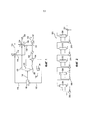
Фигура 1 схематически иллюстрирует двустадийный способ регенерации растворителя согласно настоящему изобретению.Figure 1 schematically illustrates a two-step solvent recovery method according to the present invention.
Фигура 2 схематически иллюстрирует многостадийную компрессорную линию, применяемую для сжатия и сжижения диоксида углерода генерируемого двустадийным способом регенерации растворителя.Figure 2 schematically illustrates a multi-stage compressor line used to compress and liquefy carbon dioxide generated by a two-stage solvent recovery process.
ПОДРОБНОЕ ОПИСАНИЕ НАСТОЯЩЕГО ИЗОБРЕТЕНИЯDETAILED DESCRIPTION OF THE PRESENT INVENTION
Ссылаясь на фигуру 1, двухстадийный способ регенерации растворителя 100 показан для удаления диоксида углерода из растворителя, содержащего диоксид углерода. Поток растворителя, содержащего диоксид углерода, 102 помещают под избыточное давление, применяя насос 104, и нагревают, применяя теплообменник 106, и затем подают в аппарат для продувки первой стадии 108. Первое давление составляет, соответственно, по меньшей мере, приблизительно четыре атмосферы, или, по меньшей мере, приблизительно восемь атмосфер, или, по меньшей мере, приблизительно десять атмосфер. Первая температура составляет, соответственно, по меньшей мере, приблизительно 125°C, или, по меньшей мере, приблизительно 135°C, или, по меньшей мере, приблизительно 145°C. Аппарат для продувки первой стадии может представлять собой прямоточный ребойлер или другой подходящий аппарат для продувки с нагревательными элементами.Referring to FIG. 1, a two-step solvent recovery method 100 is shown for removing carbon dioxide from a solvent containing carbon dioxide. The carbon dioxide-containing
Поток растворителя, содержащего диоксид углерода, 102 может иметь первое содержание диоксида углерода (перед любым удалением диоксида углерода) в диапазоне приблизительно 1-12% по весу, соответственно, по меньшей мере, приблизительно 8% по весу, и может быть большим или меньшим, в зависимости от конкретного растворителя и конкретного применения. Подходящие растворители включают, без ограничения, водный аммиак, аминовые растворители, такие как моноэтаноламины, диэтаноламины и триэтаноламины, водный карбонат калия, и другие известные растворители. Один подходящий растворитель представляет собой активированный N-метилдиэтаноламин (ʺaMDEAʺ), который содержит пиперазиновый активирующий агент.The carbon dioxide-containing
Диоксид углерода выдувают из растворителя, содержащего диоксид углерода, в аппарате для продувки первой стадии 108, получая первый обработанный растворитель, имеющий второе содержание диоксида углерода, которое является меньшим, чем первое содержание диоксида углерода, и первый газовый поток, содержащий диоксид углерода. Первый газовый поток, содержащий диоксид углерода, 110 покидает аппарат для продувки первой стадии 108, и его подают в конденсатор 112, который конденсирует пары воды и отделяет их от газообразного диоксида углерода. Газовый поток диоксида углерода 114 покидает конденсатор 112, и его можно направлять в сторону всасывания второй или третьей стадии сжатия многостадийной компрессорной линии, как объясняется ниже. Поток конденсированной воды 116 покидает конденсатор 112, и его смешивают с потоком конденсированной воды 128, описанным ниже. Поток первого обработанного растворителя 118 покидает аппарат для продувки первой стадии 108, и его подают в аппарат для продувки второй стадии 120 при второй температуре, которая является меньшей, чем первая температура, и втором давлении, которое является меньшим, чем первое давление.Carbon dioxide is blown out from a solvent containing carbon dioxide in a first
Первый обработанный растворитель имеет второе содержание диоксида углерода, которое является меньшим, чем первое содержание диоксида углерод, и составляет, соответственно, по меньшей мере, приблизительно на 30% меньше, или, по меньшей мере, приблизительно на 50% меньше, или, по меньшей мере, приблизительно на 75% меньше, чем первое содержание диоксида углерода. В качестве примера, когда первое содержание диоксида углерода составляет приблизительно 8-12% по весу, второе содержание диоксида углерода может составлять приблизительно 6% или меньше по весу, или приблизительно 4% или меньше по весу, или приблизительно 2% или меньше по весу. Вторая температура является, соответственно, по меньшей мере, приблизительно на 5°C меньшей, чем первая температура, или, по меньшей мере, приблизительно на 15°C меньшей, чем первая температура, или, по меньшей мере, приблизительно на 25°C меньшей, чем первая температура, и является, соответственно, не большей, чем приблизительно 130°C, или не большей, чем приблизительно 120°C, или не большей, чем приблизительно 110°C. Второе давление является, соответственно, по меньшей мере, приблизительно на 50% меньшим, чем первое давление, или, по меньшей мере, приблизительно на 60% меньшим, чем первое давление, или, по меньшей мере, приблизительно на 75% меньшим, чем первое давление, причем все описанные давления измеряли в абсолютных единицах. Например, когда первое давление составляет приблизительно 6-10 атмосфер, второе давление является, соответственно не большим, чем приблизительно три атмосферы, или не большим, чем приблизительно 1,5 атмосферы.The first treated solvent has a second carbon dioxide content that is less than the first carbon dioxide content and is, respectively, at least about 30% less, or at least about 50% less, or at least at least about 75% less than the first carbon dioxide content. By way of example, when the first carbon dioxide content is about 8-12% by weight, the second carbon dioxide content may be about 6% or less by weight, or about 4% or less by weight, or about 2% or less by weight. The second temperature is, respectively, at least about 5 ° C lower than the first temperature, or at least about 15 ° C lower than the first temperature, or at least about 25 ° C lower than the first temperature, and is, respectively, not greater than approximately 130 ° C, or not greater than approximately 120 ° C, or not greater than approximately 110 ° C. The second pressure is, respectively, at least about 50% less than the first pressure, or at least about 60% less than the first pressure, or at least about 75% less than the first pressure, and all described pressures were measured in absolute units. For example, when the first pressure is about 6-10 atmospheres, the second pressure is, respectively, not greater than about three atmospheres, or not greater than about 1.5 atmospheres.
Диоксид углерода выдувают из первого обработанного растворителя в аппарате для продувки второй стадии 120, получая второй обработанный растворитель, имеющий третье содержание диоксида углерода, которое является меньшим, чем второе содержание диоксида углерода, и второй газовый поток, содержащий диоксид углерода. Второй газовый поток, содержащий диоксид углерода, 122 покидает аппарат для продувки второй стадии 120, и его подают в конденсатор 124, который конденсирует водяной пар и отделяет его от газообразного диоксида углерода. Поток газообразного диоксида углерода 126 покидает конденсатор 124, и его подают на первую стадию компрессии многостадийной компрессорной линии, как объясняется ниже. Поток конденсированной воды 128 покидает конденсатор 124, и его добавляют ко второму потоку обработанного растворителя 130 после того, как поток 130 покидает аппарат для продувки второй стадии 120 и проходит через перекрестный 106 и холодильник 125. Второй поток обработанного растворителя 130, причем к нему добавляют поток конденсированной воды 128, становится потоком 131, и его можно транспортировать, применяя насос для растворителя 132, получая поток 133 для повторного применения в способе абсорбции диоксида углерода или для другого подходящего применения.Carbon dioxide is blown out of the first treated solvent in a second
Альтернативно, но не обязательно, второй поток обработанного растворителя 130 можно подавать в аппарат для продувки третьей стадии, чья структура и функционирование повторяет структуру и функционирование аппарата для продувки второй стадии 120, и его можно описать соответствующими номерами позиций. Аналогично, поток обработанного растворителя, покидающий аппарат для продувки третьей стадии, можно подавать в аппарат для продувки четвертой и последующих стадий, по желанию, снижая содержание диоксида углерода до очень низкого уровня. Затем, способ мог бы включать стадии выдувания диоксида углерода из второго обработанного растворителя в аппарате для продувки третьей стадии 120, получая третий обработанный растворитель, имеющий четвертое содержание диоксида углерода, которое является меньшим, чем третье содержание диоксида углерода, и третий газовый поток, содержащий диоксид углерода; удаления третьего газового потока, содержащего диоксид углерода, из аппарата для продувки третьей стадии; и извлечения третьего обработанного растворителя из аппарата для продувки третьей стадии. Затем, третий обработанный растворитель можно было бы подавать в аппарат для продувки четвертой стадии, имеющий ту же конфигурацию 120. Затем, способ мог бы включать стадии подачи третьего обработанного растворителя в аппарат для продувки четвертой стадии; выдувания диоксида углерода из третьего обработанного растворителя в аппарате для продувки четвертой стадии, получая четвертый обработанный растворитель, имеющий пятое содержание диоксида углерода, которое является меньшим, чем четвертое содержание диоксида углерода, и четвертый газовый поток, содержащий диоксид углерода; удаления четвертого газового потока, содержащего диоксид углерода, из аппарата для продувки четвертой стадии; и извлечения четвертого обработанного растворителя из аппарата для продувки четвертой стадии.Alternatively, but not necessarily, a second stream of treated
Аппарат для продувки второй стадии 120 может представлять собой стандартный расширитель или другой подходящий аппарат для продувки. Второй обработанный растворитель имеет третье содержание диоксида углерода, которое является меньшим, чем второе содержание диоксида углерода, и является, соответственно, по меньшей мере, приблизительно на 30% меньшим, или, по меньшей мере, приблизительно на 50% меньшим, или, по меньшей мере, приблизительно на 90% меньшим, чем второе содержание диоксида углерода. Например, когда второе содержание диоксида углерода составляет приблизительно 2-6% по весу, третье содержание диоксида углерода может являться не большим, чем приблизительно 4,0% по весу, или не большим, чем приблизительно 1% по весу или не большим, чем приблизительно 0,2% по весу.The second
Фигура 2 показывает HYSYS® модель шестистадийной компрессорной линии 200, которую применяют для компрессии извлеченного диоксида углерода (например, потоков 114 и 126, фигура 1) до большего давления или жидкого состояния. Компрессорная линия 200 включает компрессор первой стадии 202, соответственно, поршневой насос, холодильник первой стадии 204, компрессор второй стадии 206, холодильник второй стадии 208, компрессор третьей стадии 210, холодильник третьей стадии 212, компрессор четвертой стадии 214, холодильник четвертой стадии 216, компрессор пятой стадии 218, холодильник пятой стадии 220 и компрессор шестой стадии 222. Компрессоры 202, 206, 210, 214, 218 и 222 сжимают диоксид углерода на стадиях от исходного давления, соответствующего давлению потока диоксида углерода 114, 126 (фигура 1) до давления сжижения, достаточного для поддержания диоксида углерода в полностью жидком состоянии, например, приблизительно 150 атмосфер или 2200 фунт/кв.дюйм. Холодильники 204, 208, 212, 216 и 220 охлаждают сжатый диоксид углерода на каждой стадии, соответственно, до приблизительно температуры окружающей среды.Figure 2 shows the HYSYS® model of a six-
Поток диоксида углерода 114 (фигура 1), исходящий из аппарата для продувки первой стадии 108, обычно имеет давление, аналогичное давлению стороны низкого давления многостадийной компрессорной линии второй и третьей стадии, соответственно, по меньшей мере, приблизительно шесть атмосфер, или, по меньшей мере, приблизительно восемь атмосфер, или, по меньшей мере, приблизительно десять атмосфер, и температура равна или немного выше температуры окружающей среды, обусловленной конденсатором 112. Поскольку поток диоксида углерода 114 уже имеет значительно большее давление, чем давление со стороны низкого давления многостадийной компрессорной линии, не требуется проходить компрессорную линию 200 в компрессоре первой стадии 210, но можно, вместо этого, проходить компрессор второй стадии 214 и/или компрессор третьей стадии 218. Это приводит в результате к значительному энергосбережению и снижению расходов, по сравнению с способами извлечения диоксида углерода предшествующего уровня техники, которые требуют подачи всего количества диоксида углерода в компрессор первой стадии 202, обычно не более чем 2 атмосферы, соответственно, но не более 1,5 атмосфер.The carbon dioxide stream 114 (FIG. 1) emanating from the purge apparatus of the
Поток диоксида углерода 126, исходящий из аппарата для продувки второй стадии 120, обычно имеют давление, аналогичное второму давлению, описанному выше, обычно не более чем 2 атмосферы, соответственно, не более чем 1,5 атмосферы, и температура равна или немного выше температуры окружающей среды, обусловленной конденсатором 124. Из-за его меньшего давления, поток диоксида углерода 126 можно, соответственно, вводить в компрессорную линию 200 компрессора первой стадии 202. Однако, поскольку поток диоксида углерода 126 представляет только часть всего диоксида углерода, входящего в компрессорную линию 200 из потоков 114 и 126, суммарные энергосбережение и снижение расходов являются значительными, по сравнению с общепринятыми способами извлечения диоксида углерода, которые подают весь извлеченный диоксид углерода в первую стадию компрессорной линии. На практике, количество диоксида углерода, генерируемое из потока 126 в аппарате для продувки второй стадии 120, может находиться в диапазоне приблизительно 20-60% всего диоксида углерода, и количество диоксида углерода, генерируемое из потока 114 в аппарате для продувки первой стадии 108, может находиться в диапазоне приблизительно 30-80% всего диоксида углерода.The
ПРИМЕРЫEXAMPLES
Применяя двухстадийный способ регенерации продувкой, показанный на фигуре 1, и шестистадийную компрессорную линию, показанную на фигуре 2, диоксид углерода удаляют из aMDEA растворителя, содержащего 8% по весу активирующего агента и имеющего первоначальную загрузку диоксида углерода 5-8% по весу. Растворитель, содержащий диоксид углерода, подают в аппарат для продувки первой стадии, прямоточный ребойлер при трех наборах температур и давления: 1) 140°C и 8,16 атмосфер, 2) 130°C и 6,8 атмосфер, и 3) 120°C и 5,44 атмосфер. Для каждого прогона, извлеченный диоксид углерода сжимают и сжижают, применяя показанную компрессорную линию (фигура 2). Диоксид углерода, генерируемый в прямоточном ребойлере первой стадии, подают на вторую или третью стадию компрессорной линии. Диоксид углерода, генерируемый в расширителе второй стадии, подают на первую стадию компрессорной линии. Потребляемую мощность, требуемая для суммарного сжатия, регистрировали и сравнивали с потребляемой мощностью, требуемой для сжатия и сжижения соответствующего количества диоксида углерода, генерируемого в общепринятой десорбционной колонне и полной подаче на первую стадию компрессорной линии.Using the two-stage purge regeneration method shown in FIG. 1 and the six-stage compressor line shown in FIG. 2, carbon dioxide is removed from aMDEA solvent containing 8% by weight of activating agent and having an initial charge of carbon dioxide of 5-8% by weight. The solvent containing carbon dioxide is fed to the first stage purge apparatus, a direct-flow reboiler at three sets of temperatures and pressures: 1) 140 ° C and 8.16 atmospheres, 2) 130 ° C and 6.8 atmospheres, and 3) 120 ° C and 5.44 atmospheres For each run, the recovered carbon dioxide is compressed and liquefied using the compressor line shown (Figure 2). The carbon dioxide generated in the direct-flow reboiler of the first stage is fed to the second or third stage of the compressor line. The carbon dioxide generated in the expander of the second stage is fed to the first stage of the compressor line. The power consumption required for total compression was recorded and compared with the power required for compression and liquefaction of the corresponding amount of carbon dioxide generated in a conventional desorption column and fully fed to the first stage of the compressor line.
Результаты моделирования HYSIS® показаны в таблице 1. Как показано, чем выше первая температура и первое давление растворителя, содержащего диоксид углерода, поступающего в ребойлер первой стадии, тем больше сбережение энергии, требуемой для сжатия, по сравнению с диоксидом углерода, генерируемым в общепринятой десорбционной колонне.The HYSIS® simulation results are shown in Table 1. As shown, the higher the first temperature and first pressure of the carbon dioxide-containing solvent entering the first-stage reboiler, the greater the energy savings required for compression compared to the carbon dioxide generated in conventional desorption column.
Таблица 1Table 1
Варианты осуществления настоящего изобретения, описанные в настоящем изобретении, в настоящее время являются предпочтительными. Различные модификации и улучшения можно осуществлять, не выходя за пределы объема и сущности настоящего изобретения. Объем настоящего изобретения определен прилагаемой формулой изобретения, и все изменения, попадающие в пределы смыслового содержания и диапазона эквивалентов, предполагаются включенными в настоящее изобретение.Embodiments of the present invention described in the present invention are currently preferred. Various modifications and improvements can be made without going beyond the scope and essence of the present invention. The scope of the present invention is defined by the appended claims, and all changes that fall within the meaning and range of equivalents are intended to be included in the present invention.
Claims (50)
Applications Claiming Priority (3)
| Application Number | Priority Date | Filing Date | Title |
|---|---|---|---|
| US14/549,954 | 2014-11-21 | ||
| US14/549,954 US9901846B2 (en) | 2014-11-21 | 2014-11-21 | Energy efficient solvent regeneration process for carbon dioxide capture |
| PCT/US2015/053488 WO2016081074A1 (en) | 2014-11-21 | 2015-10-01 | Energy efficient solvent regeneration process for carbon dioxide capture |
Publications (1)
| Publication Number | Publication Date |
|---|---|
| RU2660881C1 true RU2660881C1 (en) | 2018-07-10 |
Family
ID=54540166
Family Applications (1)
| Application Number | Title | Priority Date | Filing Date |
|---|---|---|---|
| RU2017121592A RU2660881C1 (en) | 2014-11-21 | 2015-10-01 | Energy-saving method for regeneration of solvent for carbon dioxide recovery |
Country Status (10)
| Country | Link |
|---|---|
| US (1) | US9901846B2 (en) |
| EP (1) | EP3221030B1 (en) |
| JP (1) | JP2018501947A (en) |
| CN (1) | CN107073388B (en) |
| AU (1) | AU2015350538A1 (en) |
| CA (1) | CA2964096C (en) |
| NO (1) | NO20170723A1 (en) |
| PL (1) | PL3221030T3 (en) |
| RU (1) | RU2660881C1 (en) |
| WO (1) | WO2016081074A1 (en) |
Families Citing this family (6)
| Publication number | Priority date | Publication date | Assignee | Title |
|---|---|---|---|---|
| CN109833637A (en) * | 2017-11-27 | 2019-06-04 | 中国石油天然气股份有限公司 | Recyclable device |
| CN109173596B (en) * | 2018-09-05 | 2021-05-18 | 中石化上海工程有限公司 | Method for recovering pressure energy of ethylene oxide device |
| CN113840803B (en) * | 2019-05-28 | 2024-02-02 | 株式会社德山 | Method for recovering carbon dioxide gas and other gases |
| CN113694569B (en) * | 2021-09-17 | 2022-10-18 | 中国北方发动机研究所(天津) | Defoaming method and defoaming device for oil tank |
| DE102022116362A1 (en) | 2022-06-30 | 2024-01-04 | Fraunhofer-Gesellschaft zur Förderung der angewandten Forschung eingetragener Verein | Process for capturing carbon dioxide |
| WO2024054675A1 (en) * | 2022-09-09 | 2024-03-14 | Gti Energy | Clean water recirculation for steam production in rotating packed bed desorber system |
Citations (5)
| Publication number | Priority date | Publication date | Assignee | Title |
|---|---|---|---|---|
| US2826266A (en) * | 1956-07-30 | 1958-03-11 | Phillips Petroleum Co | Removal of co2 from natural gas |
| WO2010039785A1 (en) * | 2008-10-02 | 2010-04-08 | Fluor Technologies Corporation | Configurations and methods of high pressure acid gas removal |
| RU2397011C2 (en) * | 2006-01-18 | 2010-08-20 | Тоталь С.А. | Method for treatment of gas mixtures containing mercaptans and other acid gases |
| WO2012120370A2 (en) * | 2011-03-10 | 2012-09-13 | Alstom Technology Ltd | System and process for the physical absorption of carbon dioxide from a flue gas stream |
| RU2565693C2 (en) * | 2010-06-02 | 2015-10-20 | Статойл Петролеум Ас | Co2 desorption without stripper |
Family Cites Families (11)
| Publication number | Priority date | Publication date | Assignee | Title |
|---|---|---|---|---|
| NO874821L (en) * | 1986-12-02 | 1988-06-03 | Norton Co | PROCEDURE FOR AA REMOVING CARBON DIOXIDE FROM A GAS. |
| US5061465A (en) | 1989-08-24 | 1991-10-29 | Phillips Petroleum Company | Bulk CO2 recovery process |
| WO2005090887A1 (en) * | 2004-03-11 | 2005-09-29 | Advanced Extraction Technologies, Inc. | Use of cryogenic temperatures in processing gases containing light components with physical solvents |
| WO2008097839A1 (en) * | 2007-02-02 | 2008-08-14 | Chevron U.S.A. Inc. | Methods and apparatus for removing acid gases from a natural gas stream |
| US8696797B2 (en) * | 2008-05-30 | 2014-04-15 | General Electric Company | Carbon dioxide removal from synthesis gas at elevated pressure |
| CN102065976A (en) | 2008-06-26 | 2011-05-18 | 环球油品公司 | Carbon dioxide absorber partial pumparound for cooling semi-lean physical solvent |
| CN102740951B (en) | 2009-09-18 | 2015-07-29 | 氟石科技公司 | High pressure height CO2 removes structure and method |
| US20120152120A1 (en) * | 2010-12-15 | 2012-06-21 | Uop Llc | Production of carbon dioxide from synthesis gas |
| JP5972696B2 (en) * | 2012-07-20 | 2016-08-17 | 三菱重工業株式会社 | CO2 recovery system |
| GB201322606D0 (en) * | 2013-12-19 | 2014-02-05 | Capture Ltd C | System for capture and release of acid gases |
| CN103961979B (en) * | 2014-04-28 | 2015-12-30 | 中国华能集团清洁能源技术研究院有限公司 | A kind of carbon dioxide capture system of multi-stage diffluence regeneration and technique |
-
2014
- 2014-11-21 US US14/549,954 patent/US9901846B2/en active Active
-
2015
- 2015-10-01 RU RU2017121592A patent/RU2660881C1/en active
- 2015-10-01 AU AU2015350538A patent/AU2015350538A1/en not_active Abandoned
- 2015-10-01 CA CA2964096A patent/CA2964096C/en active Active
- 2015-10-01 PL PL15793938T patent/PL3221030T3/en unknown
- 2015-10-01 EP EP15793938.0A patent/EP3221030B1/en active Active
- 2015-10-01 CN CN201580060118.6A patent/CN107073388B/en active Active
- 2015-10-01 JP JP2017523865A patent/JP2018501947A/en active Pending
- 2015-10-01 WO PCT/US2015/053488 patent/WO2016081074A1/en active Application Filing
-
2017
- 2017-05-02 NO NO20170723A patent/NO20170723A1/en unknown
Patent Citations (5)
| Publication number | Priority date | Publication date | Assignee | Title |
|---|---|---|---|---|
| US2826266A (en) * | 1956-07-30 | 1958-03-11 | Phillips Petroleum Co | Removal of co2 from natural gas |
| RU2397011C2 (en) * | 2006-01-18 | 2010-08-20 | Тоталь С.А. | Method for treatment of gas mixtures containing mercaptans and other acid gases |
| WO2010039785A1 (en) * | 2008-10-02 | 2010-04-08 | Fluor Technologies Corporation | Configurations and methods of high pressure acid gas removal |
| RU2565693C2 (en) * | 2010-06-02 | 2015-10-20 | Статойл Петролеум Ас | Co2 desorption without stripper |
| WO2012120370A2 (en) * | 2011-03-10 | 2012-09-13 | Alstom Technology Ltd | System and process for the physical absorption of carbon dioxide from a flue gas stream |
Also Published As
| Publication number | Publication date |
|---|---|
| EP3221030A1 (en) | 2017-09-27 |
| NO20170723A1 (en) | 2017-05-02 |
| CN107073388A (en) | 2017-08-18 |
| US20160144295A1 (en) | 2016-05-26 |
| JP2018501947A (en) | 2018-01-25 |
| CN107073388B (en) | 2020-11-03 |
| AU2015350538A1 (en) | 2017-04-27 |
| CA2964096C (en) | 2019-01-08 |
| CA2964096A1 (en) | 2016-05-26 |
| WO2016081074A1 (en) | 2016-05-26 |
| EP3221030B1 (en) | 2019-12-04 |
| PL3221030T3 (en) | 2020-05-18 |
| US9901846B2 (en) | 2018-02-27 |
Similar Documents
| Publication | Publication Date | Title |
|---|---|---|
| RU2660881C1 (en) | Energy-saving method for regeneration of solvent for carbon dioxide recovery | |
| US8696798B2 (en) | Configurations and methods of high pressure acid gas removal | |
| US9776124B2 (en) | Configurations and methods of high pressure acid gas removal in the production of ultra-low sulfur gas | |
| US7192468B2 (en) | Configurations and method for improved gas removal | |
| US7637987B2 (en) | Configurations and methods of acid gas removal | |
| US8747520B2 (en) | Carbon dioxide capture from power or process plant gases | |
| JP2007509745A (en) | Membrane / distillation method and system for extracting CO2 from hydrocarbon gas | |
| JP2006509622A5 (en) | ||
| JP2005522326A (en) | Configuration and method for improved acid gas removal | |
| JP2013512772A (en) | Gas stripping method based on alcohol | |
| US20160166977A1 (en) | Gas-assisted stripping of liquid solvents for carbon capture | |
| US10315154B2 (en) | Method for the recovery of carbon dioxide from an absorbent with reduced supply of stripping steam | |
| AU2007201677A1 (en) | Configurations and methods for improved acid gas removal |